WO2022091764A1 - 鉄道車両用車輪 - Google Patents
鉄道車両用車輪 Download PDFInfo
- Publication number
- WO2022091764A1 WO2022091764A1 PCT/JP2021/037658 JP2021037658W WO2022091764A1 WO 2022091764 A1 WO2022091764 A1 WO 2022091764A1 JP 2021037658 W JP2021037658 W JP 2021037658W WO 2022091764 A1 WO2022091764 A1 WO 2022091764A1
- Authority
- WO
- WIPO (PCT)
- Prior art keywords
- wheel
- rim
- plate
- plate thickness
- center line
- Prior art date
- Legal status (The legal status is an assumption and is not a legal conclusion. Google has not performed a legal analysis and makes no representation as to the accuracy of the status listed.)
- Ceased
Links
Images




Classifications
-
- B—PERFORMING OPERATIONS; TRANSPORTING
- B60—VEHICLES IN GENERAL
- B60B—VEHICLE WHEELS; CASTORS; AXLES FOR WHEELS OR CASTORS; INCREASING WHEEL ADHESION
- B60B17/00—Wheels characterised by rail-engaging elements
- B60B17/0006—Construction of wheel bodies, e.g. disc wheels
-
- B—PERFORMING OPERATIONS; TRANSPORTING
- B60—VEHICLES IN GENERAL
- B60B—VEHICLE WHEELS; CASTORS; AXLES FOR WHEELS OR CASTORS; INCREASING WHEEL ADHESION
- B60B3/00—Disc wheels, i.e. wheels with load-supporting disc body
- B60B3/002—Disc wheels, i.e. wheels with load-supporting disc body characterised by the shape of the disc
- B60B3/007—Disc wheels, i.e. wheels with load-supporting disc body characterised by the shape of the disc in the intermediate section
-
- B—PERFORMING OPERATIONS; TRANSPORTING
- B60—VEHICLES IN GENERAL
- B60B—VEHICLE WHEELS; CASTORS; AXLES FOR WHEELS OR CASTORS; INCREASING WHEEL ADHESION
- B60B17/00—Wheels characterised by rail-engaging elements
- B60B17/0065—Flange details
- B60B17/0068—Flange details the flange being provided on a single side
-
- B—PERFORMING OPERATIONS; TRANSPORTING
- B60—VEHICLES IN GENERAL
- B60B—VEHICLE WHEELS; CASTORS; AXLES FOR WHEELS OR CASTORS; INCREASING WHEEL ADHESION
- B60B2900/00—Purpose of invention
- B60B2900/30—Increase in
- B60B2900/311—Rigidity or stiffness
-
- B—PERFORMING OPERATIONS; TRANSPORTING
- B60—VEHICLES IN GENERAL
- B60Y—INDEXING SCHEME RELATING TO ASPECTS CROSS-CUTTING VEHICLE TECHNOLOGY
- B60Y2200/00—Type of vehicle
- B60Y2200/30—Railway vehicles
Definitions
- This disclosure relates to wheels used in railway vehicles.
- Tread brakes are known as a type of braking method for railway vehicles.
- the tread brake is a braking method in which a brake shoe is pressed against the tread surface of a wheel of a railroad vehicle to generate a frictional force between the tread and the brake shoe, and the frictional force brakes the railroad vehicle.
- Patent Document 1 proposes a wheel including a rim portion forming an outer peripheral portion of the wheel, a boss portion forming an inner peripheral portion of the wheel, and a plate portion having a substantially S-shaped cross section.
- the displacement amount of the rim portion with respect to the boss portion and the displacement amount of the plate portion on the rim portion side are set to predetermined values or more for the purpose of reducing the thermal stress of the plate portion and the rim portion.
- the amount of displacement of the rim with respect to the boss is from the vertical line drawn from the end of the curved plate thickness center line on the rim side to the axis of the wheel and the end of the plate thickness center line on the boss side.
- the amount of displacement of the plate portion on the rim portion side is the vertical line drawn from the end of the plate thickness center line on the rim portion side to the axis of the wheel and the displacement amount from the center of the rim portion in the axial direction of the wheel to the axis of the wheel. The distance between the vertical line.
- Patent Document 2 proposes a wheel having a curved cross-sectional shape on a plate portion for the purpose of reducing thermal stress of the rim portion.
- the plate portion has a cross-sectional shape called a bell shape. Both ends of the curved plate thickness center line of the plate portion are arranged on the same side with respect to the central plane of the wheel (the plane perpendicular to the axis of the wheel). On the other hand, the midpoint of the plate thickness center line is arranged on the side opposite to both ends of the plate thickness center line with respect to the center plane of the wheel.
- the rim portion of a wheel used in a railroad vehicle is usually subjected to compressive residual stress by heat treatment or the like at the time of manufacture.
- the compressive residual stress of the rim portion may be reversed to the tensile residual stress. That is, during braking of a railroad vehicle, the friction between the tread and the brake shoe causes the temperature to rise at the rim portion and the rim portion tries to thermally expand, while the temperature rise is small on the inner peripheral side of the wheel. The thermal expansion of the rim portion is hindered, and a compressive stress in the circumferential direction of the wheel is generated particularly in the rim portion.
- Both the wheels of Patent Documents 1 and 2 have a curved plate portion. As a result, the restraint of the plate portion with respect to the thermal expansion of the rim portion is relaxed. Therefore, in the wheels of Patent Documents 1 and 2, it is considered that the thermal stress generated in the rim portion during braking of the railway vehicle is reduced and the tensile residual stress is less likely to be generated in the rim portion.
- the plate portion is curved, there is a problem that the weight of the wheel increases.
- the wheels according to the present disclosure are used for railway vehicles.
- the wheel includes a boss portion, a rim portion, and a plate portion.
- the boss portion constitutes the inner peripheral portion of the wheel.
- the axle of the railroad vehicle is inserted into the boss portion.
- the rim portion constitutes the outer peripheral portion of the wheel.
- the rim portion includes a tread and a flange.
- the tread contacts the top surface of the rail on which the railroad vehicle travels.
- the flange projects outward from the tread in the radial direction of the wheel.
- the annular plate portion connects the boss portion and the rim portion.
- the center of the rim portion in the axial direction is arranged closer to the flange in the axial direction than the center of the boss portion in the axial direction.
- the axial direction is the direction in which the central axis of the wheel extends.
- the plate portion has a linear plate thickness center line in the vertical cross-sectional view of the wheel.
- the angle formed by the plate thickness center line in the axial direction is ⁇ , and the axial distance from the side surface of the rim portion on both sides in the axial direction opposite to the flange to the radial outer end of the plate thickness center line is Pw.
- the angle ⁇ is 90 ° when the plate thickness center line is parallel to the radial direction, and the plate thickness center line rotates in the radial direction from the position of 90 ° around the inner end in the radial direction to the opposite side of the flange. It is defined as less than 90 ° when tilted with respect to.
- FIG. 1 is a vertical sectional view of a wheel according to an embodiment.
- FIG. 2 is a diagram schematically showing a wheel having a plate portion having an S-shaped cross section.
- FIG. 3 is a graph showing the relationship between the plate angle and the rim residual stress for Examples and Comparative Examples in which the value of the ratio of the plate portion position to the rim width is the same.
- FIG. 4 is a graph showing the relationship between the ratio of the plate portion position to the rim width and the rim residual stress for Examples and Comparative Examples having the same plate angle.
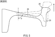
- FIG. 5 is a diagram exaggerating and illustrating the deformation generated in the wheel during braking in the embodiment.
- FIG. 1 is a vertical sectional view of a wheel according to an embodiment.
- FIG. 2 is a diagram schematically showing a wheel having a plate portion having an S-shaped cross section.
- FIG. 3 is a graph showing the relationship between the plate angle and the rim residual stress for Examples and Comparative Examples in which the value of the ratio of
- FIG. 6 is a diagram exaggeratingly exemplifying the deformation generated in the wheel during braking in an embodiment different from that in FIG.
- FIG. 7 is a diagram exaggerating and illustrating the deformation generated in the wheel during braking in the comparative example.
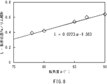
- FIG. 8 is a diagram showing a limit line in which the residual stress of the rim portion does not reverse in tension in the relationship between the plate angle and the ratio of the plate portion position to the rim width.
- the wheels according to the embodiment are used for railway vehicles.
- the wheel includes a boss portion, a rim portion, and a plate portion.
- the boss portion constitutes the inner peripheral portion of the wheel.
- the axle of the railroad vehicle is inserted into the boss portion.
- the rim portion constitutes the outer peripheral portion of the wheel.
- the rim portion includes a tread and a flange.
- the tread contacts the top surface of the rail on which the railroad vehicle travels.
- the flange projects outward from the tread in the radial direction of the wheel.
- the annular plate portion connects the boss portion and the rim portion.
- the center of the rim portion in the axial direction is arranged closer to the flange in the axial direction than the center of the boss portion in the axial direction.
- the axial direction is the direction in which the central axis of the wheel extends.
- the plate portion has a linear plate thickness center line in the vertical cross-sectional view of the wheel.
- the angle formed by the plate thickness center line in the axial direction is ⁇ , and the axial distance from the side surface of the rim portion on both sides in the axial direction opposite to the flange to the radial outer end of the plate thickness center line is Pw.
- the angle ⁇ is 90 ° when the plate thickness center line is parallel to the radial direction, and the plate thickness center line rotates in the radial direction from the position of 90 ° around the inner end in the radial direction to the opposite side of the flange. It is defined as less than 90 ° when tilted with respect to.
- the plate thickness center line of the plate portion is linear in the vertical cross-sectional view of the wheel and has no inflection point. That is, the plate portion connects the boss portion and the rim portion without substantially bending. Therefore, the weight of the plate portion can be reduced as compared with the case where the plate portion is curved. Therefore, the weight of the wheel can be reduced.
- the rim part thermally expands.
- the plate portion restrains the thermal expansion of the rim portion, thermal stress is generated in the rim portion. If the thermal stress of the rim portion becomes excessive, the rim portion may be plastically deformed during braking of the railroad vehicle, and after the rim portion is cooled, tensile residual stress in the circumferential direction of the wheel may occur.
- the wheel according to the first configuration is formed in a shape that relaxes the restraint of the rim portion by the plate portion.
- the angle of the plate thickness center line with respect to the axial direction of the wheel is assumed that the center of the rim portion is located closer to the flange than the center of the boss portion.
- the dimensions of each part are set so as to satisfy the equation (1) in consideration of both the position of the plate thickness center line with respect to the rim part.
- the plate thickness center line of the plate portion is linear in the vertical cross-sectional view of the wheel and has no inflection. In this case, stress concentration is unlikely to occur in the plate portion. Therefore, it is possible to reduce the thermal stress of the plate portion generated when the railroad vehicle is braked.
- the angle of the plate thickness center line of the plate portion with respect to the axial direction of the wheel is 90 ° or less. Therefore, the plate portion does not tilt inward in the orbit as it goes outward in the radial direction. Therefore, the rigidity of the plate portion can be ensured against the load received by the wheel from the rail in the axial direction when passing through the curve, in other words, the load received by the wheel from the inside of the track (lateral pressure). Therefore, the stress generated in the plate portion can be reduced.
- the angle ⁇ formed by the plate thickness center line in the axial direction is preferably 87 ° or less (second configuration).
- the angle of the plate thickness center line of the plate portion with respect to the axial direction of the wheel is 87 ° or less.
- the plate portion tilts to the outside of the track as it goes outward in the radial direction. Therefore, the rigidity of the plate portion with respect to the lateral pressure can be improved, and the stress generated in the plate portion can be further reduced. Further, since the necessity of increasing the plate thickness of the plate portion in order to secure the rigidity of the plate portion with respect to the lateral pressure is reduced, the weight of the plate portion and the wheels can be further reduced.
- the plate portion may have a plate thickness that becomes smaller toward the outside in the radial direction and becomes the minimum before the outer end of the plate thickness center line (third configuration).
- FIG. 1 is a vertical cross-sectional view of the wheel 100 according to the present embodiment.
- the vertical cross section means a cross section obtained by cutting the wheel 100 on a plane including the central axis X. Since the vertical cross section of the wheel 100 is symmetrical with respect to the central axis X, FIG. 1 shows only one side of the central axis X of the wheels 100.
- the direction in which the central axis X of the wheel 100 extends is referred to as an axial direction
- the radial direction and the circumferential direction of the wheel 100 are simply referred to as a radial direction and a circumferential direction, respectively.
- the wheel 100 is used for a railroad vehicle.
- the wheel 100 includes a boss portion 10, a rim portion 20, and a plate portion 30.
- the boss portion 10 constitutes the inner peripheral portion of the wheel 100.
- the boss portion 10 has a substantially cylindrical shape with the central axis X as the axis.
- An axle (not shown) of a railway vehicle is inserted into the boss portion 10.
- the rim portion 20 constitutes the outer peripheral portion of the wheel 100.
- the rim portion 20 is arranged outside the boss portion 10 in the radial direction.
- the rim portion 20 includes a tread surface 21 and a flange 22.
- the tread 21 and the flange 22 are provided on the outer peripheral surface of the rim portion 20.
- the tread 21 is a surface facing outward in the radial direction.
- the tread 21 contacts the top surface of the rail on which the railroad vehicle travels.
- the diameter of the tread 21 typically gradually increases toward the flange 22 side.
- the tread 21 may be, for example, a conical tread or an arc tread.
- the flange 22 is provided at one end in the axial direction of the rim portion 20.
- the flange 22 projects outward from the tread 21 in the radial direction.
- the flange 22 is positioned inside the left and right rails when the railroad vehicle travels on the rails.
- the side on which the flange 22 is arranged is referred to as the flange direction, and the opposite side thereof is referred to as the anti-flange direction.
- the rim portion 20 further includes both side surfaces 23 and 24 in the axial direction.
- the side surface 23 is a side surface on the flange 22 side
- the side surface 24 is a side surface opposite to the flange 22. That is, the side surface 23 is arranged in the flange direction with respect to the side surface 24.
- the side surface 24 sandwiches the tread surface 21 and the flange 22, and is arranged in the anti-flange direction with respect to the side surface 23.
- the rim portion 20 is arranged in the flange direction with respect to the boss portion 10. More specifically, the central Cr of the rim portion 20 in the axial direction is arranged closer to the flange 22 in the axial direction than the central Cb of the boss portion 10 in the axial direction. When the railroad vehicle travels, the central Cr of the rim portion 20 is positioned inside the central Cb of the boss portion 10 in the track width direction.
- the plate portion 30 forms a ring.
- the plate portion 30 connects the boss portion 10 and the rim portion 20.
- the plate thickness of the plate portion 30 is smaller than each of the boss width Wb and the rim width Wr as a whole.
- the plate thickness of the plate portion 30 is large on the boss portion 10 side and small on the rim portion 20 side.
- the boss width Wb means the length of the boss portion 10 in the axial direction.
- the rim width Wr is the length of the rim portion 20 in the axial direction, and is the maximum distance in the axial direction from the side surface 23 to the side surface 24 of the rim portion 20.
- the plate portion 30 includes both side surfaces 31 and 32 in the axial direction.
- the side surface 31 is a side surface on the flange 22 side
- the side surface 32 is a side surface opposite to the flange 22. That is, the side surface 31 is arranged in the flange direction with respect to the side surface 32.
- the side surface 32 is arranged in the anti-flange direction with respect to the side surface 31.
- the side surfaces 31 and 32 are preferably inclined with respect to the radial direction.
- the side surfaces 31 and 32 are connected to the rim portion 20 via the connecting portions 41 and 42, respectively.
- the side surfaces 31 and 32 are connected to the boss portion 10 via the connecting portions 43 and 44, respectively.
- Each of the connecting portions 41, 42, 43, 44 is substantially arcuate, for example, in a vertical cross-sectional view of the wheel 100.
- the end (R stop) 411 on the plate portion 30 side of the connection portion 41 and the end (R stop) 421 on the plate portion 30 side of the connection portion 42 those located more inward in the radial direction are used. It is defined as the outer peripheral edge of the plate portion 30.
- the end (R stop) 431 on the plate portion 30 side of the connection portion 43 and the end (R stop) 441 on the plate portion 30 side of the connection portion 44 the one located on the outer side in the radial direction is the plate portion 30. It is defined as the inner peripheral end of.
- the outer peripheral edge of the plate portion 30 can be said to be the base of the plate portion 30 with respect to the rim portion 20.
- the inner peripheral end of the plate portion 30 can be said to be the base of the plate portion 30 with respect to the boss portion 10.
- the end 411 of the connecting portion 41 and the end 441 of the connecting portion 44 are the outer peripheral end and the inner peripheral end of the plate portion 30, respectively.
- the plate thickness of the plate portion 30 decreases toward the outside in the radial direction and becomes the minimum before the outer peripheral end 411.
- the plate portion 30 has a minimum plate thickness inside the outer peripheral end 411 in the radial direction and in the vicinity of the outer peripheral end 411.
- the position where the plate thickness of the plate portion 30 is minimized substantially coincides with the position where the bending stress generated in the plate portion 30 due to the bending load received from the rail by the wheel 100 when the railroad vehicle passes the curve is minimized. do.
- the plate thickness of the plate portion 30 can be minimized at a position 5 mm to 30 mm inward in the radial direction from the outer peripheral end 411.
- the plate portion 30 has a plate thickness center line A.
- the plate thickness center line A is a line formed by connecting the plate thickness centers of the plate portions 30 extending from the boss portion 10 to the rim portion 20 in the vertical cross-sectional view of the wheel 100.
- the plate thickness center line A extends from the boss portion 10 side to the rim portion 20 side through the middle of the side surfaces 31 and 32.
- the plate thickness center line A is linear in the vertical cross-sectional view of the wheel 100.
- the linear shape here is a concept that includes not only a perfect straight line but also a very gentle arc having a radius of curvature of 1000 mm or more and a polygonal line.
- the plate thickness center line A may be anything that can be recognized as being substantially straight in the vertical cross-sectional view of the wheel 100. Since the plate thickness center line A is linear in the vertical cross-sectional view of the wheel 100, the plate portion 30 has a substantially flat plate shape and does not substantially bend in the axial direction.
- the plate thickness center line A has an outer end Aa in the radial direction and an inner end Ab in the radial direction.
- the outer end Aa is a point where the plate thickness center line A is connected to a straight line extending in the axial direction through the outer peripheral end 411 of the plate portion 30.
- the inner end Ab of the plate thickness center line A is a point where the plate thickness center line A is connected to a straight line extending in the axial direction through the inner peripheral end 441 of the plate portion 30.
- the position of the plate portion 30 with respect to the rim portion 20 is determined by the axial position of the outer end Aa of the plate thickness center line A.
- the distance in the axial direction from the side surface 24 in the anti-flange direction to the outer end Aa of the plate thickness center line A among the side surfaces 23 and 24 of the rim portion 20 is defined as the plate portion position Pw.
- the ratio of the plate portion position Pw to the rim width Wr: the smaller L Pw / Wr, the farther the outer peripheral end 411 of the plate portion 30 is from the flange 22, and the larger the ratio L, the more the outer peripheral end 411 of the plate portion 30 becomes the flange 22. Will be approaching.
- the ratio of the plate portion position Pw to the rim width Wr: L Pw / Wr is determined in relation to the angle ⁇ of the plate thickness center line A.
- the ratio L of the plate portion position Pw to the rim width Wr and the angle ⁇ of the plate thickness center line A are determined to satisfy the following equation (1). L ⁇ 0.0223 ⁇ -1.363 ... (1)
- the angle ⁇ of the plate thickness center line A is the angle formed by the plate thickness center line A with respect to the axial direction in the vertical cross-sectional view of the wheel 100.
- the angle ⁇ is the angle formed by the tangent line at the center of the plate thickness center line A (the intermediate point between the outer end Aa and the inner end Ab) with respect to the axial direction.
- the angle ⁇ is an angle formed by the longest line segment among the line segments constituting the plate thickness center line A with respect to the axial direction.
- the angle ⁇ is defined as 90 ° when the plate thickness center line A is parallel to the radial direction.
- the angle ⁇ is set when the plate thickness center line A is tilted with respect to the radial direction. Defined to be less than 90 °. That is, when the outer end Aa of the plate thickness center line A is arranged in the anti-flange direction with respect to the position where the angle ⁇ is 90 °, it is assumed that the angle ⁇ is less than 90 °.
- the angle ⁇ of the plate thickness center line A is set to 90 ° or less. Although it depends on the specifications of the tread brake used for the wheel 100, the angle ⁇ is preferably 87 ° or less. As the angle ⁇ becomes smaller and the plate portion 30 tilts in the direction opposite to the flange, the restraint of the rim portion 20 by the plate portion 30 is relaxed, and the deformation of the rim portion 20 during braking of the railway vehicle becomes easier to be allowed. From the viewpoint of manufacturability of the wheel 100, the angle ⁇ is preferably 75 ° or more.
- the ratio L of the plate portion position Pw to the rim width Wr becomes larger and the base of the plate portion 30 with respect to the rim portion 20 approaches the flange 22, the restraint of the rim portion 20 by the plate portion 30 is relaxed, and the braking of the railway vehicle is performed. Deformation of the rim portion 20 inside is easily allowed.
- the ratio L is preferably set in the range of 0.3 or more and 0.7 or less from the viewpoint of manufacturability of the wheel 100 and the like.
- both the angle ⁇ of the plate thickness center line A and the ratio L of the plate portion position Pw to the rim width Wr are set so that the restraint of the rim portion 20 by the plate portion 30 is relaxed. It is set properly.
- the central Cr of the rim portion 20 is located closer to the flange 22 than the central Cb of the boss portion 10, and the plate portion 30 and the plate thickness center line A thereof are located on the wheel 100.
- the angle ⁇ of the plate thickness center line A and the ratio L of the plate portion position Pw to the rim width Wr are set so as to satisfy the relationship of the above equation (1) on the premise that the plate is linear in the vertical cross section. ing.
- the plate portion The degree of restraint of the rim portion 20 by 30 can be effectively reduced. Therefore, when the brake shoe of the tread brake is pressed against the tread surface 21 of the rim portion 20 to generate frictional heat, the thermal expansion of the rim portion 20 is less likely to be hindered. Therefore, when the tread brake is used for braking the railway vehicle, the thermal stress of the rim portion 20 generated by the tread brake can be reduced, and the plastic deformation of the rim portion 20 can be suppressed. As a result, after the rim portion 20 is cooled, it is possible to prevent the residual stress of the rim portion 20 from reversing in tension.
- the plate thickness center line A of the plate portion 30 is linear in the vertical cross-sectional view of the wheel 100 and has no inflection point. That is, the plate portion 30 connects the boss portion 10 and the rim portion 20 without being substantially curved. Therefore, the weight of the plate portion 30 can be reduced as compared with the case where the plate portion 30 is curved. Therefore, the weight of the wheel 100 can be reduced.
- the plate thickness center line A is linear and the plate portion 30 is not substantially curved, stress concentration in the plate portion 30 can be alleviated during braking of the railway vehicle by the tread brake. Therefore, it is possible to reduce the thermal stress of the plate portion 30 generated when the railroad vehicle is braked.
- the plate portion 30 when the plate portion 30 is tilted in the flange direction (inside the track) as it goes outward in the radial direction, the load that the wheel 100 receives from the rail in the axial direction when passing through a curve, that is, the wheel 100 is pushed in the flange direction by the rail.
- the rigidity of the plate portion 30 with respect to a load becomes low.
- the angle ⁇ of the plate thickness center line A is set to 90 ° or less, the plate portion 30 does not substantially tilt in the flange direction as it goes outward in the radial direction. .. Therefore, the rigidity of the plate portion 30 with respect to the lateral pressure can be ensured. Therefore, the stress generated in the plate portion 30 can be reduced.
- the angle ⁇ of the plate thickness center line A is preferably 87 ° or less.
- the plate portion 30 is tilted in the anti-flange direction (outside the track) toward the outside in the radial direction.
- the rigidity of the plate portion 30 with respect to the lateral pressure can be improved, and the stress generated in the plate portion 30 can be further reduced.
- the rim portion 20 is a plate. It becomes easy to be restrained by the portion 30. Therefore, it is preferable that the side surfaces 31 and 32 of the plate portion 30 are inclined with respect to the radial direction of the wheel 100. Each of the side surfaces 31 and 32 may be inclined with respect to the radial direction so as to be toward the anti-flange direction (outside the track) as it approaches the rim portion 20, for example. By inclining the side surfaces 31 and 32 in the radial direction, the restraint of the rim portion 20 by the plate portion 30 can be further relaxed.
- the plate thickness of the plate portion 30 decreases toward the outside in the radial direction, and becomes the minimum before the outer end Aa of the plate thickness center line A. More specifically, in the plate portion 30, the position where the bending stress generated by the bending load received from the rail when passing through the curve is minimized and the position where the plate thickness is minimized are substantially matched. By doing so, it is possible to prevent fatigue fracture of the plate portion 30 and improve the durability of the wheel 100.
- FIG. 2 is a diagram schematically showing a wheel having a plate portion having an S-shaped cross section. Table 1 shows the conditions for the parameters ⁇ and L.
- FEM analysis was performed using general-purpose software (ABAQUS Ver.6.12, manufactured by Dassault Systèmes).
- ABAQUS Ver.6.12 manufactured by Dassault Systèmes.
- the braking time was 1200 seconds, and the inner circumference of the wheel was completely restrained.
- Table 2 shows the residual stress (rim residual stress) of the rim portion obtained by FEM analysis.
- the rim residual stress indicates the maximum circumferential stress of the rim portion after braking and cooling. If the rim residual stress is a negative value, it means that the residual stress of the rim part is compressed even after braking, and if the rim residual stress is a positive value, it means that the residual stress of the rim part has turned to tension after braking. ing.
- FIG. 3 is a graph showing the relationship between the plate angle ⁇ and the rim residual stress for Example 1, Comparative Example 1, and Comparative Example 2 in which the value of the ratio L of the plate portion position Pw to the rim width Wr is equal.
- the value of the rim residual stress increases as the plate angle ⁇ increases. Therefore, it can be said that if the plate angle ⁇ becomes smaller, the possibility that the residual stress of the rim portion turns into tension after braking of the railway vehicle is reduced.
- FIG. 4 is a graph showing the relationship between the ratio L of the plate portion position Pw to the rim width Wr and the rim residual stress for Example 3, Comparative Example 2, and Comparative Example 3 having the same plate angle ⁇ .
- FIG. 4 it can be seen that the larger the ratio L of the plate portion position Pw to the rim width Wr, the smaller the value of the rim residual stress. Therefore, it can be said that the larger the ratio L, the lower the possibility that the residual stress of the rim portion turns into tension after braking the railway vehicle.
- FIGS. 5 to 7 are diagrams illustrating and exemplifying the deformation that occurs in the wheel during braking in Example 1, Example 2, and Comparative Example 2, respectively.
- Example 1 where the plate angle ⁇ is as small as 80 °, as shown in FIG. 5, when the heat flux is applied to the tread surface 21, the rim portion 20 moves significantly in the flange direction. That is, in Example 1, since the plate angle ⁇ is small, the restraint of the plate portion 30 with respect to the movement of the rim portion 20 in the flange direction is reduced, and the thermal expansion of the rim portion 20 can be allowed. Therefore, in the first embodiment, the thermal stress generated in the rim portion 20 during braking is reduced, and the residual stress of the rim portion 20 remains compressed even after braking.
- Example 2 where the ratio L of the plate portion position Pw to the rim width Wr is 0.580, which is relatively large, as shown in FIG. 6, when the heat flux is applied to the tread surface 21, the rim portion 20 rotates in the flange direction. .. That is, in Example 2, since the ratio L was secured, the restraint of the plate portion 30 with respect to the rotation of the rim portion 20 in the flange direction was reduced, and the thermal expansion of the rim portion 20 could be allowed. Therefore, in the second embodiment, the thermal stress generated in the rim portion 20 during braking is reduced, and the residual stress of the rim portion 20 remains compressed even after braking.
- Comparative Example 2 in which the plate angle ⁇ is 90 °, which is larger than that of Example 1, and the ratio L of the plate portion position Pw to the rim width Wr is 0.448, which is smaller than that of Example 2. Then, as shown in FIG. 7, the movement and rotation of the rim portion 20 hardly occurred.
- the plate portion 30 was largely restrained by the movement and rotation of the rim portion 20, and when a heat flux was applied to the tread surface 21, the thermal expansion of the rim portion 20 was hindered. Therefore, in Comparative Example 2, the thermal stress generated in the rim portion 20 during braking became large, and the residual stress in the rim portion 20 was reversed to tension after braking.
- FIG. 8 shows a limit line in which the residual stress of the rim portion does not reverse to tension in the relationship between the plate angle ⁇ and the ratio L.
- the rim residual stress becomes compression. Therefore, the case where the residual stress of the rim portion can be substantially prevented from becoming tension is the case where the plate angle ⁇ and the ratio L satisfy the following equation (1).
- the plate angle ⁇ is 90 ° or less.
Landscapes
- Engineering & Computer Science (AREA)
- Mechanical Engineering (AREA)
- Braking Arrangements (AREA)
Abstract
Description
L≧0.0223α-1.363・・・(1)
ただし、角度αは、90°以下である。角度αは、板厚中心線が半径方向と平行な場合に90°であり、板厚中心線が90°の位置から半径方向の内端を中心としてフランジの反対側に回転することで半径方向に対して傾いている場合に90°未満であると定義される。
L≧0.0223α-1.363・・・(1)
ただし、角度αは、90°以下である。角度αは、板厚中心線が半径方向と平行な場合に90°であり、板厚中心線が90°の位置から半径方向の内端を中心としてフランジの反対側に回転することで半径方向に対して傾いている場合に90°未満であると定義される。
L≧0.0223α-1.363・・・(1)
本実施形態に係る車輪100では、板部30によるリム部20の拘束が緩和されるように、板厚中心線Aの角度αと、リム幅Wrに対する板部位置Pwの比率Lとの双方を適切に設定している。具体的には、本実施形態では、リム部20の中央Crがボス部10の中央Cbと比較してフランジ22寄りに位置し、且つ、板部30及びその板厚中心線Aが車輪100の縦断面視で直線状であることを前提として、上記式(1)の関係を満足するように、板厚中心線Aの角度α、及びリム幅Wrに対する板部位置Pwの比率Lが設定されている。これにより、リム部20の中央Crがボス部10の中央Cbと比較してフランジ22寄りに位置し、且つ、板部30及びその板厚中心線Aが直線状である車輪100において、板部30によるリム部20の拘束の程度を効果的に低減することができる。そのため、リム部20の踏面21に踏面ブレーキの制輪子が押し付けられて摩擦熱が発生したとき、リム部20の熱膨張が阻害されにくくなる。よって、鉄道車両の制動に踏面ブレーキを使用する際、この踏面ブレーキに起因して発生するリム部20の熱応力を低減することができ、リム部20の塑性変形を抑制することができる。その結果、リム部20が冷却された後、リム部20の残留応力が引張に反転するのを抑制することができる。


L≧0.0223α-1.363・・・(1)

10:ボス部
20:リム部
21:踏面
22:フランジ
30:板部
A:板厚中心線
Claims (3)
- 鉄道車両に用いられる車輪であって、
前記車輪の内周部を構成し、前記鉄道車両の車軸が挿入されるボス部と、
前記車輪の外周部を構成し、前記鉄道車両が走行するレールの頭頂面に接触する踏面と、前記車輪の半径方向で前記踏面よりも外側に突出するフランジと、を含むリム部と、
前記ボス部と前記リム部とを接続する環状の板部と、
を備え、
前記車輪の中心軸が延びる方向である軸方向における前記リム部の中央は、前記軸方向における前記ボス部の中央よりも、前記軸方向において前記フランジ寄りに配置されており、
前記板部は、前記車輪の縦断面視で直線状の板厚中心線を有し、
前記板厚中心線が前記軸方向となす角度であって、前記板厚中心線が前記半径方向と平行な場合に90°であり、前記板厚中心線が90°の位置から前記半径方向の内端を中心として前記フランジと反対側に回転することで前記半径方向に対して傾いている場合に90°未満であると定義される前記角度をαとし、
前記リム部の前記軸方向の両側面のうち前記フランジと反対側の側面から、前記板厚中心線の前記半径方向の外端までの前記軸方向における距離をPwとし、前記軸方向における前記リム部の長さをWrとし、Pw/WrをLとしたとき、以下の式(1)を満たす、車輪。
L≧0.0223α-1.363・・・(1)
ただし、前記角度αは、90°以下である。 - 請求項1に記載の車輪であって、
前記角度αは、87°以下である、車輪。 - 請求項1又は2に記載の車輪であって、
前記板部は、前記半径方向の外側に向かうにつれて小さくなり前記板厚中心線の前記外端の手前で最小となる板厚を有する、車輪。
Priority Applications (4)
| Application Number | Priority Date | Filing Date | Title |
|---|---|---|---|
| US18/004,916 US12454148B2 (en) | 2020-10-27 | 2021-10-12 | Wheel for railway vehicle |
| JP2022558977A JP7393703B2 (ja) | 2020-10-27 | 2021-10-12 | 鉄道車両用車輪 |
| CN202180072565.9A CN116419854B (zh) | 2020-10-27 | 2021-10-12 | 铁道车辆用车轮 |
| EP21885883.5A EP4238781B1 (en) | 2020-10-27 | 2021-10-12 | Wheel for railway vehicle |
Applications Claiming Priority (2)
| Application Number | Priority Date | Filing Date | Title |
|---|---|---|---|
| JP2020179613 | 2020-10-27 | ||
| JP2020-179613 | 2020-10-27 |
Publications (1)
| Publication Number | Publication Date |
|---|---|
| WO2022091764A1 true WO2022091764A1 (ja) | 2022-05-05 |
Family
ID=81383734
Family Applications (1)
| Application Number | Title | Priority Date | Filing Date |
|---|---|---|---|
| PCT/JP2021/037658 Ceased WO2022091764A1 (ja) | 2020-10-27 | 2021-10-12 | 鉄道車両用車輪 |
Country Status (5)
| Country | Link |
|---|---|
| US (1) | US12454148B2 (ja) |
| EP (1) | EP4238781B1 (ja) |
| JP (1) | JP7393703B2 (ja) |
| CN (1) | CN116419854B (ja) |
| WO (1) | WO2022091764A1 (ja) |
Cited By (2)
| Publication number | Priority date | Publication date | Assignee | Title |
|---|---|---|---|---|
| WO2024053617A1 (ja) | 2022-09-08 | 2024-03-14 | 日本製鉄株式会社 | 車輪 |
| EP4424521A4 (en) * | 2021-10-29 | 2025-03-12 | Nippon Steel Corporation | WHEEL FOR RAIL VEHICLE |
Citations (4)
| Publication number | Priority date | Publication date | Assignee | Title |
|---|---|---|---|---|
| JPS5634504A (en) * | 1979-08-31 | 1981-04-06 | Sumitomo Metal Ind Ltd | Wheel for railway vehicle |
| JPH10119503A (ja) | 1996-10-18 | 1998-05-12 | Sumitomo Metal Ind Ltd | 耐割損性に優れた鉄道車両用車輪及びその製造方法 |
| JP2004050880A (ja) * | 2002-07-17 | 2004-02-19 | Railway Technical Res Inst | 鉄道車両用車輪 |
| JP2009545484A (ja) * | 2006-08-04 | 2009-12-24 | ルッチーニ アールエス エス.ピー.エー. | 高い制動能力を備えた貨物鉄道車輪 |
Family Cites Families (12)
| Publication number | Priority date | Publication date | Assignee | Title |
|---|---|---|---|---|
| DE2306650C3 (de) | 1973-02-10 | 1980-02-07 | Schwaebische Huettenwerke Gmbh, 7080 Aalen | Schienenrad mit einer Radscheibe |
| DE19630824A1 (de) * | 1996-07-31 | 1998-02-05 | Vsg Verkehrstechnik Gmbh | Schienenrad mit Radnabe, einteiligem Radkranz und Radnabe und Radkranz verbindender Radscheibe |
| NL1008966C2 (nl) | 1998-04-22 | 1999-10-25 | Skf Eng & Res Centre Bv | Spoorwegvoertuigwiel met verbeterde dempingseigenschappen. |
| CZ20022774A3 (cs) * | 2002-08-15 | 2004-01-14 | Bonatrans A.S. | Železniční kolo s vyrovnaným napěťovým polem |
| JP2004131002A (ja) * | 2002-10-11 | 2004-04-30 | Sumitomo Metal Ind Ltd | 鉄道用車輪 |
| US7739794B2 (en) * | 2008-02-29 | 2010-06-22 | General Electric Company | Method for repair of rail wheels |
| DE102011121785A1 (de) * | 2011-12-21 | 2013-06-27 | Voith Patent Gmbh | Radscheibe für ein Schienenfahrzeug |
| DE102013007447A1 (de) * | 2013-05-02 | 2014-11-06 | Voith Patent Gmbh | Radscheibe für ein Schienenfahrzeug |
| CN103507560A (zh) * | 2013-10-11 | 2014-01-15 | 北京二七轨道交通装备有限责任公司 | 列车车轮及列车 |
| CN203485669U (zh) * | 2013-10-11 | 2014-03-19 | 北京二七轨道交通装备有限责任公司 | 列车车轮及列车 |
| CN107415575B (zh) * | 2017-06-26 | 2020-05-15 | 西南交通大学 | 一种能够明显减少钢轨波磨的铁路车轮 |
| EP3978265B1 (en) * | 2019-05-29 | 2023-12-13 | Nippon Steel Corporation | Wheel for railway vehicle |
-
2021
- 2021-10-12 US US18/004,916 patent/US12454148B2/en active Active
- 2021-10-12 EP EP21885883.5A patent/EP4238781B1/en active Active
- 2021-10-12 CN CN202180072565.9A patent/CN116419854B/zh active Active
- 2021-10-12 JP JP2022558977A patent/JP7393703B2/ja active Active
- 2021-10-12 WO PCT/JP2021/037658 patent/WO2022091764A1/ja not_active Ceased
Patent Citations (4)
| Publication number | Priority date | Publication date | Assignee | Title |
|---|---|---|---|---|
| JPS5634504A (en) * | 1979-08-31 | 1981-04-06 | Sumitomo Metal Ind Ltd | Wheel for railway vehicle |
| JPH10119503A (ja) | 1996-10-18 | 1998-05-12 | Sumitomo Metal Ind Ltd | 耐割損性に優れた鉄道車両用車輪及びその製造方法 |
| JP2004050880A (ja) * | 2002-07-17 | 2004-02-19 | Railway Technical Res Inst | 鉄道車両用車輪 |
| JP2009545484A (ja) * | 2006-08-04 | 2009-12-24 | ルッチーニ アールエス エス.ピー.エー. | 高い制動能力を備えた貨物鉄道車輪 |
Non-Patent Citations (1)
| Title |
|---|
| See also references of EP4238781A4 |
Cited By (3)
| Publication number | Priority date | Publication date | Assignee | Title |
|---|---|---|---|---|
| EP4424521A4 (en) * | 2021-10-29 | 2025-03-12 | Nippon Steel Corporation | WHEEL FOR RAIL VEHICLE |
| AU2022377622B2 (en) * | 2021-10-29 | 2025-11-27 | Nippon Steel Corporation | Wheel for railway vehicle |
| WO2024053617A1 (ja) | 2022-09-08 | 2024-03-14 | 日本製鉄株式会社 | 車輪 |
Also Published As
| Publication number | Publication date |
|---|---|
| EP4238781A1 (en) | 2023-09-06 |
| JP7393703B2 (ja) | 2023-12-07 |
| EP4238781A4 (en) | 2024-03-13 |
| CN116419854B (zh) | 2026-01-13 |
| US12454148B2 (en) | 2025-10-28 |
| EP4238781B1 (en) | 2025-02-19 |
| US20230294453A1 (en) | 2023-09-21 |
| CN116419854A (zh) | 2023-07-11 |
| JPWO2022091764A1 (ja) | 2022-05-05 |
Similar Documents
| Publication | Publication Date | Title |
|---|---|---|
| JP7197004B2 (ja) | 鉄道車両用車輪 | |
| WO2022091764A1 (ja) | 鉄道車両用車輪 | |
| TWI572790B (zh) | 帶制動盤的鐵道車輪 | |
| JP7637471B2 (ja) | 鉄道車輪 | |
| JP7701650B2 (ja) | 鉄道車両用車輪 | |
| AU2022434993B2 (en) | Wheel for railway vehicle | |
| JP7437716B2 (ja) | 鉄道車両用車輪 | |
| JP2004131002A (ja) | 鉄道用車輪 | |
| JP7807699B2 (ja) | 車輪 | |
| JP2024107525A (ja) | 車輪 | |
| JP3114777B2 (ja) | 鉄道車両用車輪 | |
| JP5690128B2 (ja) | 自動車用ホイール | |
| JP2005214263A (ja) | 鉄道車両用ブレーキディスク |
Legal Events
| Date | Code | Title | Description |
|---|---|---|---|
| 121 | Ep: the epo has been informed by wipo that ep was designated in this application |
Ref document number: 21885883 Country of ref document: EP Kind code of ref document: A1 |
|
| ENP | Entry into the national phase |
Ref document number: 2022558977 Country of ref document: JP Kind code of ref document: A |
|
| NENP | Non-entry into the national phase |
Ref country code: DE |
|
| ENP | Entry into the national phase |
Ref document number: 2021885883 Country of ref document: EP Effective date: 20230530 |
|
| WWG | Wipo information: grant in national office |
Ref document number: 18004916 Country of ref document: US |