WO2022091908A1 - Échangeur de chaleur et réfrigérateur - Google Patents
Échangeur de chaleur et réfrigérateur Download PDFInfo
- Publication number
- WO2022091908A1 WO2022091908A1 PCT/JP2021/038762 JP2021038762W WO2022091908A1 WO 2022091908 A1 WO2022091908 A1 WO 2022091908A1 JP 2021038762 W JP2021038762 W JP 2021038762W WO 2022091908 A1 WO2022091908 A1 WO 2022091908A1
- Authority
- WO
- WIPO (PCT)
- Prior art keywords
- storage material
- cold storage
- heat exchanger
- container
- refrigerant
- Prior art date
- Legal status (The legal status is an assumption and is not a legal conclusion. Google has not performed a legal analysis and makes no representation as to the accuracy of the status listed.)
- Ceased
Links
Images




Classifications
-
- F—MECHANICAL ENGINEERING; LIGHTING; HEATING; WEAPONS; BLASTING
- F25—REFRIGERATION OR COOLING; COMBINED HEATING AND REFRIGERATION SYSTEMS; HEAT PUMP SYSTEMS; MANUFACTURE OR STORAGE OF ICE; LIQUEFACTION SOLIDIFICATION OF GASES
- F25B—REFRIGERATION MACHINES, PLANTS OR SYSTEMS; COMBINED HEATING AND REFRIGERATION SYSTEMS; HEAT PUMP SYSTEMS
- F25B39/00—Evaporators; Condensers
- F25B39/02—Evaporators
-
- F—MECHANICAL ENGINEERING; LIGHTING; HEATING; WEAPONS; BLASTING
- F25—REFRIGERATION OR COOLING; COMBINED HEATING AND REFRIGERATION SYSTEMS; HEAT PUMP SYSTEMS; MANUFACTURE OR STORAGE OF ICE; LIQUEFACTION SOLIDIFICATION OF GASES
- F25D—REFRIGERATORS; COLD ROOMS; ICE-BOXES; COOLING OR FREEZING APPARATUS NOT OTHERWISE PROVIDED FOR
- F25D16/00—Devices using a combination of a cooling mode associated with refrigerating machinery with a cooling mode not associated with refrigerating machinery
-
- F—MECHANICAL ENGINEERING; LIGHTING; HEATING; WEAPONS; BLASTING
- F28—HEAT EXCHANGE IN GENERAL
- F28D—HEAT-EXCHANGE APPARATUS, NOT PROVIDED FOR IN ANOTHER SUBCLASS, IN WHICH THE HEAT-EXCHANGE MEDIA DO NOT COME INTO DIRECT CONTACT
- F28D1/00—Heat-exchange apparatus having stationary conduit assemblies for one heat-exchange medium only, the media being in contact with different sides of the conduit wall, in which the other heat-exchange medium is a large body of fluid, e.g. domestic or motor car radiators
- F28D1/02—Heat-exchange apparatus having stationary conduit assemblies for one heat-exchange medium only, the media being in contact with different sides of the conduit wall, in which the other heat-exchange medium is a large body of fluid, e.g. domestic or motor car radiators with heat-exchange conduits immersed in the body of fluid
- F28D1/04—Heat-exchange apparatus having stationary conduit assemblies for one heat-exchange medium only, the media being in contact with different sides of the conduit wall, in which the other heat-exchange medium is a large body of fluid, e.g. domestic or motor car radiators with heat-exchange conduits immersed in the body of fluid with tubular conduits
- F28D1/047—Heat-exchange apparatus having stationary conduit assemblies for one heat-exchange medium only, the media being in contact with different sides of the conduit wall, in which the other heat-exchange medium is a large body of fluid, e.g. domestic or motor car radiators with heat-exchange conduits immersed in the body of fluid with tubular conduits the conduits being bent, e.g. in a serpentine or zig-zag
-
- F—MECHANICAL ENGINEERING; LIGHTING; HEATING; WEAPONS; BLASTING
- F28—HEAT EXCHANGE IN GENERAL
- F28D—HEAT-EXCHANGE APPARATUS, NOT PROVIDED FOR IN ANOTHER SUBCLASS, IN WHICH THE HEAT-EXCHANGE MEDIA DO NOT COME INTO DIRECT CONTACT
- F28D20/00—Heat storage plants or apparatus in general; Regenerative heat-exchange apparatus not covered by groups F28D17/00 or F28D19/00
- F28D20/02—Heat storage plants or apparatus in general; Regenerative heat-exchange apparatus not covered by groups F28D17/00 or F28D19/00 using latent heat
-
- Y—GENERAL TAGGING OF NEW TECHNOLOGICAL DEVELOPMENTS; GENERAL TAGGING OF CROSS-SECTIONAL TECHNOLOGIES SPANNING OVER SEVERAL SECTIONS OF THE IPC; TECHNICAL SUBJECTS COVERED BY FORMER USPC CROSS-REFERENCE ART COLLECTIONS [XRACs] AND DIGESTS
- Y02—TECHNOLOGIES OR APPLICATIONS FOR MITIGATION OR ADAPTATION AGAINST CLIMATE CHANGE
- Y02E—REDUCTION OF GREENHOUSE GAS [GHG] EMISSIONS, RELATED TO ENERGY GENERATION, TRANSMISSION OR DISTRIBUTION
- Y02E60/00—Enabling technologies; Technologies with a potential or indirect contribution to GHG emissions mitigation
- Y02E60/14—Thermal energy storage
Definitions
- This disclosure relates to heat exchangers and refrigerators having a cold storage function.
- Patent Document 1 discloses a refrigerator.
- This refrigerator has a cooler that cools the storage chamber by operating a compressor and a cooling chamber that houses the cooler.
- the heat storage material and the cooling amount of the cooler are used to cool the storage chamber when the load is applied when the food is taken in and out.
- the temperature rise in the storage chamber is reduced, and the drive speed of the compressor is cooled while operating at a lower rotation speed than before, so that the cooling performance is improved while suppressing the operation due to the high rotation speed of the compressor. Therefore, the energy efficiency can be improved.
- the present disclosure provides a heat exchanger and a refrigerator capable of efficiently cooling the cold storage material with a refrigerant and saving energy by using the cooled cold storage material.
- the heat exchanger in the present disclosure includes a refrigerant conducting member made of flat pipes formed at intervals from each other, and a cold storage material container arranged in a gap between the flat pipes adjacent to the refrigerant conducting member and containing a cold storage material.
- the cold storage material container is made of a flexible metal.
- the cold storage material container is formed of a material, and is characterized in that the cold storage material container is press-fitted into the gaps between the flat tubes and is in close contact with and fixed to the flat tubes.
- the heat exchanger in the present disclosure can reduce the thermal resistance from the flat tube to the cold storage material by bringing the cold storage material container into close contact with the flat tube, and efficiently cools the cold storage material by the refrigerant flowing through the flat tube. be able to. Therefore, energy saving can be achieved by cooling the cold storage material.
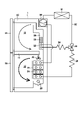
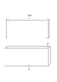
- FIG. 1 is a schematic cross-sectional view showing an outline of the refrigerator according to the first embodiment.
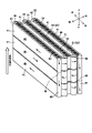
- FIG. 2 is a perspective view showing the heat exchanger for refrigeration according to the first embodiment.
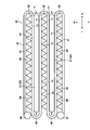
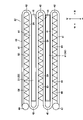
- FIG. 3 is a plan view showing the heat exchanger for refrigeration according to the first embodiment.
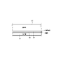
- FIG. 4 is a front view showing the heat exchanger for refrigeration according to the first embodiment.
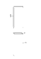
- FIG. 5 is a diagram showing a contact state between the flat tube of the first embodiment and the cold storage material.
- FIG. 6 is a block diagram showing the control configuration of the first embodiment.
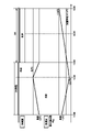
- FIG. 7 is a graph showing the operation corresponding to the demand response.
- FIG. 8 is a plan view showing the heat exchanger for refrigeration according to the second embodiment.
- FIG. 9 is a perspective view showing a cold storage material portion of the second embodiment.
- FIG. 10 is a diagram showing a contact state between the flat tube of the second embodiment and the cold storage material.
- FIG. 11 is a perspective view showing another example of the cold storage material portion of the second embodiment.
- FIG. 12 is a perspective view showing a cold storage material portion of the third embodiment.
- FIG. 13 is a diagram showing a contact state between the flat tube of the third embodiment and the cold storage material.
- the cold storage material was placed in contact with or close to the cooler that cools the storage room by operating the compressor, and the storage room was cooled by the cooling heat of the cooler and the cold storage material.
- the cold storage material is composed of a resin case and is arranged in the space between the side walls of the cooling chamber on the side of the cooler, so that the refrigerant pipe and the cold storage material are separated from each other.
- the present disclosure provides a heat exchanger and a refrigerator capable of efficiently cooling the cold storage material with a refrigerant and saving energy by using the cooled cold storage material.
- FIG. 1 is a schematic cross-sectional view showing an outline of a refrigerator according to the present invention.
- the refrigerator 1 includes a box-shaped main body 10.
- a partition plate 11 for partitioning the internal space of the main body 10 is provided at a substantially central portion in the vertical direction of the main body 10.
- the upper side of the partition plate 11 is a refrigerating chamber 12, and the lower side of the partition plate 11 is a freezing chamber 13.
- a refrigerating room door 14 is provided openable and closable on the front surface of the refrigerating room 12, and a freezing room door 15 is provided on the front surface of the freezing room 13 so as to be openable and closable.
- a refrigerating duct 20 extending in the vertical direction is provided at the rear of the refrigerating chamber 12.
- a freezing duct 21 extending in the vertical direction is provided at the rear of the freezing chamber 13.
- a refrigerating heat exchanger 22 as the heat exchanger of the present invention is housed inside the refrigerating duct 20, a refrigerating heat exchanger 22 as the heat exchanger of the present invention is housed.
- a refrigerating fan 23 is arranged above the refrigerating heat exchanger 22. Then, by driving the refrigerating fan 23, the internal air of the refrigerating chamber 12 is sucked from below the refrigerating duct 20, heat is exchanged through the refrigerating heat exchanger 22, and then above the refrigerating duct 20. It is configured to be blown out from the inside of the refrigerating chamber 12.
- a freezing heat exchanger 24 is housed inside the freezing duct 21.
- a freezing fan 25 is arranged above the refrigerating heat exchanger 24. Then, by driving the freezing fan 25, the internal air of the freezing chamber 13 is sucked from below the freezing duct 21, heat is exchanged through the freezing heat exchanger 24, and then above the freezing duct 21. It is configured to be blown out from the inside of the freezing chamber 13.
- a heater 26 is arranged below the freezing duct 21.
- a compressor 30 is installed above the rear portion of the main body 10.
- a condenser 31 is connected to the compressor 30 via a refrigerant pipe 32.
- a three-way valve 33 is connected to the condenser 31, and a refrigerating heat exchanger 22 is connected to the three-way valve 33 via an expansion mechanism 34. Further, a refrigerating heat exchanger 24 is connected to the three-way valve 33 via an expansion mechanism 35. Then, a refrigerating refrigerant cycle is formed in which the refrigerant sequentially circulates through the compressor 30, the condenser 31, the three-way valve 33, the expansion mechanism 34, and the refrigerating heat exchanger 22, and the compressor 30, the condenser 31, and the three-way valve are formed.
- a refrigerating refrigerant cycle is formed in which the refrigerant sequentially circulates through 33, the expansion mechanism 35, and the refrigerating heat exchanger 24.
- the refrigerating refrigerant cycle and the freezing refrigerant cycle can be switched by switching the three-way valve 33.
- FIG. 2 is a perspective view showing the refrigerating heat exchanger 22 of the first embodiment.
- FIG. 3 is a plan view showing the refrigerating heat exchanger 22 of the first embodiment.
- FIG. 4 is a front view showing the refrigerating heat exchanger 22 of the first embodiment.
- the refrigerating heat exchanger 22 includes a refrigerant conduction member 40 through which a refrigerant flows.
- the refrigerant conduction member 40 is composed of a perforated flat tube in which a plurality of substantially square passages are continuously arranged.
- the refrigerant conduction member 40 is formed in a meandering shape including a plurality of flat pipes 41 formed substantially parallel to each other at predetermined intervals and a curved portion 42 connecting the ends of the flat pipes 41.
- the flat tube 41 is composed of six between the headers described later.
- the number of flat tubes 41 is not limited to this, and can be set arbitrarily. Further, each flat tube 41 and the curved portion 42 may be integrally formed by meandering one flat tube 41 between the headers.
- the flat tube 41 and the curved portion 42 are vertically divided into three upper regions 43, a middle region 44, and a lower region 45.
- the region is divided into three regions in the vertical direction, but it may be divided into two regions or four or more regions in the vertical direction.
- An inlet side header 46 and an outlet side header 47 extending vertically are provided at one end of the flat tube 41 located on the outermost side, respectively.
- the inlet side header 46 and the outlet side header 47 are attached so as not to protrude from the end surface of the refrigerant conduction member 40. That is, the end faces of the inlet side header 46 and the outlet side header 47 are flush with the outer surface of the flat pipe 41 of the refrigerant conduction member 40.
- the thickness dimension of the refrigerant conducting member 40 can be reduced, and when the refrigerant conducting member 40 is housed inside the refrigerating duct 20, the internal space of the refrigerating duct 20 can be reduced. As a result, the internal space of the refrigerator compartment 12 can be increased.
- the refrigerant is configured to flow in from the upper part of the inlet side header 46, and the refrigerant is configured to flow out from the lower part of the outlet side header 47.
- the inlet side header 46 and the outlet side header 47 may be provided at different ends of the flat pipe 41, and the inlet side header 46 and the outlet side header 47 may be arranged on both sides of the refrigerant conduction member 40. .. Further, the refrigerant inlet of the inlet side header 46 may be provided below instead of above, and the refrigerant outlet of the outlet side header 47 may be provided above instead of below.
- a partition plate 48 is provided at a position corresponding to the boundary between the upper region 43 and the middle region 44 of the inlet side header 46.
- the positions corresponding to the middle region 44 and the lower region 45 of the entrance side header 46 communicate with each other.
- a partition plate 49 is provided at a position corresponding to the boundary between the middle region 44 and the lower region 45 of the exit side header 47.
- the positions corresponding to the upper region 43 and the middle region 44 of the exit side header 47 communicate with each other.
- the refrigerant flowing in from the upper part of the inlet side header 46 passes through the inside of the upper region 43 of the refrigerant conduction member 40 and flows to the outlet side header 47.
- the refrigerant flowing to the outlet side header 47 flows into the central region 44 of the refrigerant conduction member 40, flows to the inlet side header 46, flows through the lower region 45 via the inlet side header 46, and then flows to the lower part of the outlet side header 47. Leaked from. That is, the refrigerant conducting member 40 is arranged so that its width direction (vertical direction in FIG. 4) is directed to the air flow direction in the refrigerating duct 20, and the refrigerant flowing through the refrigerant conducting member 40 is in the air flow direction. It flows in the direction orthogonal to the.
- the air flow path 50 and the cold storage material container 52 in which the cold storage material 51 is enclosed are alternately arranged between the flat pipes 41 of the refrigerant conduction member 40.
- air flow paths 50 are formed in the outermost and central portions, and a cold storage material container 52 is arranged between the air flow paths 50.
- fins 54 that are inclined at a predetermined angle with respect to the flat tube 41 and are continuously provided by being bent in a zigzag shape are arranged, and the inside of the air flow path 50 is provided by these fins 54.
- air flow paths 50 having a substantially triangular cross-sectional shape are continuously formed.
- an air flow path having a rectangular cross-sectional shape may be continuously formed.
- the air flow path 50 is formed in the vertical direction along the vertical direction of the refrigerating duct 20. Then, as shown in FIG. 2, the air inside the refrigerator sent from the refrigerating duct 20 flows from the lower side to the upper side of the refrigerating heat exchanger 22.
- the air inside the refrigerator flowing from the lower side to the upper side of the refrigerating duct 20 flows through the air flow path 50, and at this time, heat exchanges with the refrigerant flowing inside the refrigerant conducting member 40 and is cooled to a predetermined temperature. It is configured to be. Further, the cold storage material 51 is also configured to be cooled to a predetermined temperature by exchanging heat between the refrigerant flowing inside the refrigerant conduction member 40 and the cold storage material 51.
- the cold storage material container 52 is made of a thin film member made of a metal material such as aluminum.
- the cold storage material container 52 has flexibility and can be deformed.
- the thickness dimension of the cold storage material container 52 is configured to have substantially the same dimension as the gap of each flat pipe 41. Then, by pressing the cold storage material container 52 into the gap between the flat pipes 41, the cold storage material container 52 comes into close contact with the surface of each flat pipe 41, whereby the cold storage material container 52 is placed between the flat pipes 41. It is possible to hold it.
- the open side end portion of the flat tube 41 is provided with a restraint member 55 for preventing the open side end portion from expanding.
- a restraint member 55 for example, a wire-shaped member such as a wire is used.
- a plate-shaped member fixed to the end face of the flat tube 41 may be used.
- a bottom plate or the like may be provided below the gap of the flat pipe 41.
- the cold storage material 51 needs to cool the low temperature chamber (about -3 ° C) in the refrigerating chamber 12 cooled to about 3 ° C, the cold storage material 51 having a melting point lower than -3 ° C, for example, has a melting point of ⁇ A cold storage material 51 at 5 ° C to ⁇ 15 ° C is used.
- the cold storage material 51 is a mixture of water, a gel agent, a preservative, and a coloring agent, if the cold storage material container 52 is made of a metal material, it is corroded by water. There is a risk. Therefore, in general, a corrosion-resistant layer 56 made of resin or the like is provided on the inner surface of the cold storage material container 52.
- a cold storage material is provided in an air conditioner, and the air conditioner is efficiently operated by cooling the cold storage material.
- the temperature is relatively high. Since the cold storage material is cooled in, it is not necessary to use the cold storage material below the freezing point as in the present embodiment.
- a paraffin-based cold storage material is generally used, so that no corrosion-resistant layer is required on the inner surface of the cold storage material container.
- the flat tube 41 is in contact with the cold storage material container 52, the corrosion resistant layer 56, and the cold storage material 51 in this order.
- the cold storage material container 52 that is in close contact with the flat pipe 41 can reduce the heat resistance from the flat pipe 41 to the cold storage material 51, and the refrigerant flowing through the flat pipe 41 can efficiently cool the cold storage material 51. can.
- the corrosion resistant layer since the corrosion resistant layer is unnecessary, it is not necessary to consider the reduction of thermal resistance more than necessary as in the present embodiment.
- the lower end of the fin 54 is located below the lower end of the refrigerant conducting member 40.
- the upper end of the fin 54 may be positioned above the upper end of the refrigerant conduction member 40. As a result, since the fins 54 are cooled by the refrigerant, the heat exchange efficiency of the air inside the refrigerator can be improved.
- FIG. 6 is a block diagram showing the control configuration of the first embodiment.
- the refrigerator 1 includes a control unit 60.
- the control unit 60 includes, for example, a processor that executes a program such as a CPU and an MPU, and a memory such as a ROM and a RAM, so that the processor reads a control program stored in the memory and executes a process. Various processes are executed by the cooperation of software.
- the control unit 60 controls the compressor 30, the refrigerating fan 23, the refrigerating fan 25, the three-way valve 33, and the heater 26 based on the detected temperatures of the refrigerating room temperature sensor 61 and the refrigerating room temperature sensor 62.
- the refrigerant sent to the refrigerating heat exchanger 24 exchanges heat with the internal air flowing from below to above the refrigerating duct 21 by driving the refrigerating fan 25, and the refrigerant cooled by the refrigerant is refrigerated. Returned to room 13.
- FIG. 7 is a graph showing an operation corresponding to a demand response.
- the control of the present embodiment is a control of stopping the compressor 30 in a time zone of 1 hour before and after 14:00, which is the peak of power consumption.
- the refrigerator 1 receives a demand response signal requesting that power consumption be suppressed from an external server such as an electric power company at 11 o'clock.
- the device that has received the demand response signal needs to be switched to the operation of suppressing the power consumption after 2 hours.
- the compressor 30 is stopped at 13:00
- the control is started after an instruction is received from the outside at 11 o'clock two hours ago.
- the refrigerator 1 starts the demand response control.
- the control unit 60 switches the three-way valve 33 at 11 o'clock to control the flow of the refrigerant to the refrigerating heat exchanger 24.
- the refrigerant discharged from the compressor 30 is sent to the refrigerating heat exchanger 24 through the condenser 31 and the expansion mechanism 35.
- the refrigerant sent to the refrigerating heat exchanger 24 exchanges heat with the internal air in the refrigerating heat exchanger 24 to cool the inside of the freezing chamber 13 to a predetermined temperature.
- the predetermined temperature in this case is usually set lower than the set internal temperature.
- the cooling is controlled to be cooled from, for example, about -19 ° C to about -24 ° C.
- the control unit 60 switches the three-way valve 33 to control the flow of the refrigerant to the refrigerating heat exchanger 22.
- the refrigerant discharged from the compressor 30 is sent to the refrigerating heat exchanger 22 through the condenser 31 and the expansion mechanism 34.
- the refrigerant sent to the refrigerating heat exchanger 22 exchanges heat with the internal air in the refrigerating heat exchanger 22 to cool the inside of the refrigerating chamber 12 to a predetermined temperature.
- the cold storage material 51 is cooled by the refrigerant flowing through the refrigerating heat exchanger 22, and the cold storage material 51 is stored cold.
- the control unit 60 stops the compressor 30 at 13:00.
- the refrigerator 1 executes an operation of suppressing power consumption.
- the temperature of the refrigerating chamber 12 can be maintained at a substantially constant temperature due to the cooling capacity of the cold storage material 51, and the temperature of the freezing chamber 13 gradually rises but the demand response control ends at 15:00. However, it can be maintained at an appropriate temperature.
- the cold storage material 51 is arranged in the gap between the refrigerant conducting member 40 made of the flat pipes 41 formed at intervals from each other and the adjacent flat pipes 41 of the refrigerant conducting member 40.
- the cold storage material container 52 is provided with an air flow path 50 formed between other parts of the flat pipe 41 and through which air flows, and fins 54 provided in the air flow path 50. It is made of a flexible metal material, and the cold storage material container 52 is press-fitted into the gaps of the flat pipes 41 and is closely fixed to the flat pipes 41.
- the thermal resistance from the flat pipe 41 to the cold storage material 51 can be reduced by bringing the cold storage material container 52 made of a metal material into close contact with the flat pipe 41, and the refrigerant flowing through the flat pipe 41 efficiently stores cold.
- the material 51 can be cooled. Therefore, the operating time of the compressor 30 for cooling the cold storage material 51 with the cooler is shortened, and energy saving can be achieved. Further, the efficient heat exchange between the cold storage material 51 and the cooler improves the heat exchange efficiency of the cooler and improves the cooling efficiency in the refrigerating cycle, so that the operating time of the compressor 30 is further shortened. It is possible to further save energy.
- a restraining member 55 for preventing the expansion of the gap is provided at the open side end portion in the gap of each flat pipe 41.
- FIG. 8 is a plan view showing the second embodiment of the present invention.
- FIG. 9 is a perspective view showing the cold storage material container 52 and the cold storage material storage container.
- the cold storage material storage container 57 is used as a means for holding the cold storage material container 52.
- the cold storage material storage container 57 is a box-shaped container made of a metal material such as aluminum, and an opening 58 is formed in the upper portion of the cold storage material storage container 57.
- the cold storage material storage container 57 is made of the same material as the fin 54, and in the step of heat welding the flat tube 41 and the fin 54, the cold storage material storage container 57 is also heat welded together to form the flat tube 41. It can be fixed in the gap.
- the cold storage material container 52 is made of a thin film member made of a metal material such as aluminum.
- the cold storage material container 52 has flexibility and can be deformed.
- the thickness dimension of the cold storage material container 52 is configured to have substantially the same dimension as the inner width dimension of the cold storage material storage container 57. Then, by press-fitting the cold storage material container 52 into the inside of the cold storage material storage container 57 through the opening 58, the cold storage material container 52 comes into close contact with the inner surface of the cold storage material storage container 57. Since the other configurations are the same as those in the first embodiment, the same parts are designated by the same reference numerals and the description thereof will be omitted.
- the flat tube 41 is provided with the cold storage material storage container 57, the cold storage material container 52, and the corrosion resistant material.
- the layer 56 and the cold storage material 51 are in contact with each other in this order, and the cold storage material storage container 57 and the cold storage material container 52 that are in close contact with the flat tube 41 can reduce the heat resistance from the flat tube 41 to the cold storage material 51.
- the cold storage material 51 can be efficiently cooled by the refrigerant flowing through the flat tube 41. Therefore, the operating time of the compressor 30 for cooling the cold storage material 51 with the refrigerant is shortened, and energy saving can be achieved. Further, the efficient heat exchange between the cold storage material 51 and the cooler improves the heat exchange capacity of the cooler and improves the cooling efficiency in the refrigeration cycle, so that the operating time of the compressor 30 can be further shortened. , Further energy saving can be achieved.
- the opening 58 of the cold storage material storage container 57 is formed upward, but for example, as shown in FIG. 11, an opening 58 is formed on the side surface of the cold storage material storage container 57 to store cold.
- the cold storage material container 52 may be inserted from the lateral direction of the material storage container 57.
- FIG. 12 is a plan view showing the third embodiment of the present invention.
- the cold storage material container 52 is formed of a resin material, and the cold storage material 51 is enclosed inside the cold storage material container 52.
- the resin for example, ABS resin or the like is used. Since the cold storage material container 52 is made of a resin material, the cold storage material container 52 is not deformed as in the first and second embodiments. Further, since the cold storage material container 52 is made of a resin material, there is no risk of corrosion due to the moisture contained in the cold storage material 51, so that no corrosion resistant layer is provided.
- the cold storage material container 52 is fixed in the gap of the flat tube 41 by the adhesive 59. Since the other configurations are the same as those in the first and second embodiments, the same parts are designated by the same reference numerals and the description thereof will be omitted.
- the flat tube 41 is in contact with the adhesive 59, the cold storage material container 52, and the cold storage material 51 in this order.
- the cold storage material container 52 that adheres to the flat tube 41 via the adhesive 59 is slightly inferior to the case where the cold storage material container 52 made of a metal material as in the first or second embodiment is used, but the flat tube is slightly inferior.
- the heat resistance from the cold storage material 51 to the cold storage material 51 can be reduced, and the cold storage material 51 can be efficiently cooled by the refrigerant flowing through the flat pipe 41.
- the operating time of the compressor 30 for cooling the cold storage material 51 with the refrigerant is shortened, and energy saving can be achieved. Further, the efficient heat exchange between the cold storage material 51 and the cooler improves the heat exchange capacity of the cooler and improves the cooling efficiency in the refrigeration cycle, so that the operating time of the compressor 30 can be further shortened. , Further energy saving can be achieved.
- the first to third embodiments have been described as examples of the techniques disclosed in the present application.
- the technique in the present disclosure is not limited to this, and can be applied to embodiments in which changes, replacements, additions, omissions, etc. have been made. It is also possible to combine the components described in the first to third embodiments to form a new embodiment.
- the present disclosure is applicable to a refrigerator in which the cold storage material can be efficiently cooled by the refrigerant and the air inside the refrigerator can be cooled by the cooled cold storage material to save energy.
- Refrigerator 10 Main body 11 Partition plate 12 Refrigerator room 13 Refrigerator room 14 Refrigerator room door 15 Refrigerator room door 20 Refrigerator duct 21 Refrigerator duct 22 Refrigerator heat exchanger 23 Refrigerator fan 24 Refrigerator heat exchanger 25 Refrigerator fan 26 Heater 30 Compressor 31 Condenser 32 Refrigerator piping 33 Three-way valve 34 Expansion mechanism 35 Expansion mechanism 40 Refrigerator conduction member 41 Flat tube 42 Curved part 43 Upper area 44 Middle area 45 Lower area 46 Inlet side header 46a Refrigerator inlet 47 Exit side header 47a Refrigerator outlet 48 Partition plate 49 Partition plate 50 Air flow path 51 Cold storage material 52 Cold storage material container 54 Fin 55 Restraint member 56 Corrosion resistant layer 57 Cold storage material storage container 58 Opening 59 Adhesive 60 Control unit
Landscapes
- Engineering & Computer Science (AREA)
- Physics & Mathematics (AREA)
- Thermal Sciences (AREA)
- Mechanical Engineering (AREA)
- General Engineering & Computer Science (AREA)
- Chemical & Material Sciences (AREA)
- Combustion & Propulsion (AREA)
- Devices That Are Associated With Refrigeration Equipment (AREA)
- Heat-Exchange Devices With Radiators And Conduit Assemblies (AREA)
Abstract
La présente invention concerne un échangeur de chaleur qui est capable de refroidir efficacement un matériau de stockage de froid par l'intermédiaire d'un réfrigérant et qui est capable de réaliser des économies d'énergie par l'intermédiaire du matériau de stockage de froid refroidi. La présente invention comporte : un élément de guidage de réfrigérant (40) comprenant des tuyaux plats (41) avec des espaces entre eux ; des contenants de matériau de stockage de froid (52) qui sont disposés dans les espaces entre certains des tuyaux plats (41) qui sont adjacents dans l'élément de guidage de réfrigérant (40), et dans lesquels un matériau de stockage de froid (51) est scellé ; un canal d'air (50) qui est formé entre l'autre des tuyaux plats (41) et à travers lequel s'écoule de l'air ; et des ailettes (54) fournies au canal d'air (50). Les contenants de matériau de stockage de froid (52) sont formés au moyen d'un matériau métallique flexible, et les contenants de matériau de stockage de froid (52) sont étroitement fixés aux tuyaux plats (41) en étant ajustés par pression dans les espaces entre les tuyaux plats (41).
Priority Applications (1)
| Application Number | Priority Date | Filing Date | Title |
|---|---|---|---|
| CN202180072757.XA CN116391100A (zh) | 2020-10-26 | 2021-10-20 | 热交换器和冷藏库 |
Applications Claiming Priority (2)
| Application Number | Priority Date | Filing Date | Title |
|---|---|---|---|
| JP2020-179063 | 2020-10-26 | ||
| JP2020179063A JP7731065B2 (ja) | 2020-10-26 | 2020-10-26 | 熱交換器および冷蔵庫 |
Publications (1)
| Publication Number | Publication Date |
|---|---|
| WO2022091908A1 true WO2022091908A1 (fr) | 2022-05-05 |
Family
ID=81382393
Family Applications (1)
| Application Number | Title | Priority Date | Filing Date |
|---|---|---|---|
| PCT/JP2021/038762 Ceased WO2022091908A1 (fr) | 2020-10-26 | 2021-10-20 | Échangeur de chaleur et réfrigérateur |
Country Status (3)
| Country | Link |
|---|---|
| JP (2) | JP7731065B2 (fr) |
| CN (1) | CN116391100A (fr) |
| WO (1) | WO2022091908A1 (fr) |
Cited By (1)
| Publication number | Priority date | Publication date | Assignee | Title |
|---|---|---|---|---|
| WO2023210200A1 (fr) * | 2022-04-26 | 2023-11-02 | パナソニックIpマネジメント株式会社 | Refroidisseur |
Citations (8)
| Publication number | Priority date | Publication date | Assignee | Title |
|---|---|---|---|---|
| JPH01129587U (fr) * | 1988-02-23 | 1989-09-04 | ||
| JPH0448179A (ja) * | 1990-06-15 | 1992-02-18 | Sanden Corp | 冷却コンテナ |
| JPH0712776B2 (ja) * | 1985-07-16 | 1995-02-15 | 日本電装株式会社 | 車両用冷房冷凍冷蔵装置 |
| JPH09292196A (ja) * | 1996-03-01 | 1997-11-11 | Denso Corp | 蓄冷式冷房装置 |
| JPH11294928A (ja) * | 1998-04-09 | 1999-10-29 | Daikin Ind Ltd | 保冷ボックス |
| JP2000171126A (ja) * | 1998-12-09 | 2000-06-23 | Mitsubishi Cable Ind Ltd | 蓄冷冷却システム |
| JP2002048456A (ja) * | 2000-07-31 | 2002-02-15 | Sanyo Electric Co Ltd | 冷却貯蔵庫 |
| US20070039712A1 (en) * | 2002-09-11 | 2007-02-22 | Webasto Ag | Cold or heat accumulator and process for its manufacture |
-
2020
- 2020-10-26 JP JP2020179063A patent/JP7731065B2/ja active Active
-
2021
- 2021-10-20 CN CN202180072757.XA patent/CN116391100A/zh active Pending
- 2021-10-20 WO PCT/JP2021/038762 patent/WO2022091908A1/fr not_active Ceased
-
2025
- 2025-07-31 JP JP2025127916A patent/JP2025142350A/ja active Pending
Patent Citations (8)
| Publication number | Priority date | Publication date | Assignee | Title |
|---|---|---|---|---|
| JPH0712776B2 (ja) * | 1985-07-16 | 1995-02-15 | 日本電装株式会社 | 車両用冷房冷凍冷蔵装置 |
| JPH01129587U (fr) * | 1988-02-23 | 1989-09-04 | ||
| JPH0448179A (ja) * | 1990-06-15 | 1992-02-18 | Sanden Corp | 冷却コンテナ |
| JPH09292196A (ja) * | 1996-03-01 | 1997-11-11 | Denso Corp | 蓄冷式冷房装置 |
| JPH11294928A (ja) * | 1998-04-09 | 1999-10-29 | Daikin Ind Ltd | 保冷ボックス |
| JP2000171126A (ja) * | 1998-12-09 | 2000-06-23 | Mitsubishi Cable Ind Ltd | 蓄冷冷却システム |
| JP2002048456A (ja) * | 2000-07-31 | 2002-02-15 | Sanyo Electric Co Ltd | 冷却貯蔵庫 |
| US20070039712A1 (en) * | 2002-09-11 | 2007-02-22 | Webasto Ag | Cold or heat accumulator and process for its manufacture |
Cited By (1)
| Publication number | Priority date | Publication date | Assignee | Title |
|---|---|---|---|---|
| WO2023210200A1 (fr) * | 2022-04-26 | 2023-11-02 | パナソニックIpマネジメント株式会社 | Refroidisseur |
Also Published As
| Publication number | Publication date |
|---|---|
| CN116391100A (zh) | 2023-07-04 |
| JP2022070051A (ja) | 2022-05-12 |
| JP7731065B2 (ja) | 2025-08-29 |
| JP2025142350A (ja) | 2025-09-30 |
Similar Documents
| Publication | Publication Date | Title |
|---|---|---|
| JP7627858B2 (ja) | 冷蔵庫 | |
| EP3220081B1 (fr) | Réfrigérateur à semi-conducteurs | |
| EP3220080B1 (fr) | Dispositif d'échange de chaleur d'extrémité froide et réfrigérateur à semi-conducteurs | |
| WO2014017060A1 (fr) | Evaporateur | |
| JP2025142350A (ja) | 熱交換器および冷蔵庫 | |
| US7036332B2 (en) | Heat exchanger arrangement | |
| JP2005345061A (ja) | 冷蔵庫 | |
| EP3882551A1 (fr) | Échangeur de chaleur | |
| JP2835267B2 (ja) | 冷蔵庫 | |
| JP7759536B2 (ja) | 冷蔵庫 | |
| JP5020159B2 (ja) | 熱交換器、冷蔵庫及び空調装置 | |
| CN115875900A (zh) | 用于冷藏冷冻装置的控制方法及冷藏冷冻装置 | |
| JPH11294928A (ja) | 保冷ボックス | |
| WO2023095527A1 (fr) | Réfrigérateur | |
| CN119713688A (zh) | 冷藏库 | |
| JPH07294084A (ja) | 蓄熱装置 | |
| JP2017030391A (ja) | 車両用空調装置 | |
| WO2023210200A1 (fr) | Refroidisseur | |
| JP3072209B2 (ja) | 蓄熱装置 | |
| JPH08327203A (ja) | 低温庫 | |
| JPS6383566A (ja) | 冷蔵庫 | |
| WO2021171356A1 (fr) | Réfrigérateur | |
| JP2001021246A (ja) | 冷却装置及びその冷却器 | |
| KR20090008265U (ko) | 열교환기 | |
| JPS63150583A (ja) | 蓄熱式熱交換器 |
Legal Events
| Date | Code | Title | Description |
|---|---|---|---|
| 121 | Ep: the epo has been informed by wipo that ep was designated in this application |
Ref document number: 21886027 Country of ref document: EP Kind code of ref document: A1 |
|
| NENP | Non-entry into the national phase |
Ref country code: DE |
|
| 122 | Ep: pct application non-entry in european phase |
Ref document number: 21886027 Country of ref document: EP Kind code of ref document: A1 |