WO2022158486A1 - Dispositif de transport sans contact - Google Patents
Dispositif de transport sans contact Download PDFInfo
- Publication number
- WO2022158486A1 WO2022158486A1 PCT/JP2022/001767 JP2022001767W WO2022158486A1 WO 2022158486 A1 WO2022158486 A1 WO 2022158486A1 JP 2022001767 W JP2022001767 W JP 2022001767W WO 2022158486 A1 WO2022158486 A1 WO 2022158486A1
- Authority
- WO
- WIPO (PCT)
- Prior art keywords
- contact
- facing surface
- ejection
- conveying device
- head
- Prior art date
- Legal status (The legal status is an assumption and is not a legal conclusion. Google has not performed a legal analysis and makes no representation as to the accuracy of the status listed.)
- Ceased
Links
Images




Classifications
-
- B—PERFORMING OPERATIONS; TRANSPORTING
- B65—CONVEYING; PACKING; STORING; HANDLING THIN OR FILAMENTARY MATERIAL
- B65G—TRANSPORT OR STORAGE DEVICES, e.g. CONVEYORS FOR LOADING OR TIPPING, SHOP CONVEYOR SYSTEMS OR PNEUMATIC TUBE CONVEYORS
- B65G51/00—Conveying articles through pipes or tubes by fluid flow or pressure; Conveying articles over a flat surface, e.g. the base of a trough, by jets located in the surface
- B65G51/02—Directly conveying the articles, e.g. slips, sheets, stockings, containers or workpieces, by flowing gases
- B65G51/03—Directly conveying the articles, e.g. slips, sheets, stockings, containers or workpieces, by flowing gases over a flat surface or in troughs
-
- B—PERFORMING OPERATIONS; TRANSPORTING
- B65—CONVEYING; PACKING; STORING; HANDLING THIN OR FILAMENTARY MATERIAL
- B65G—TRANSPORT OR STORAGE DEVICES, e.g. CONVEYORS FOR LOADING OR TIPPING, SHOP CONVEYOR SYSTEMS OR PNEUMATIC TUBE CONVEYORS
- B65G47/00—Article or material-handling devices associated with conveyors; Methods employing such devices
- B65G47/74—Feeding, transfer, or discharging devices of particular kinds or types
- B65G47/90—Devices for picking-up and depositing articles or materials
- B65G47/91—Devices for picking-up and depositing articles or materials incorporating pneumatic, e.g. suction, grippers
- B65G47/911—Devices for picking-up and depositing articles or materials incorporating pneumatic, e.g. suction, grippers with air blasts producing partial vacuum
-
- B—PERFORMING OPERATIONS; TRANSPORTING
- B25—HAND TOOLS; PORTABLE POWER-DRIVEN TOOLS; MANIPULATORS
- B25J—MANIPULATORS; CHAMBERS PROVIDED WITH MANIPULATION DEVICES
- B25J15/00—Gripping heads and other end effectors
- B25J15/06—Gripping heads and other end effectors with vacuum or magnetic holding means
-
- B—PERFORMING OPERATIONS; TRANSPORTING
- B25—HAND TOOLS; PORTABLE POWER-DRIVEN TOOLS; MANIPULATORS
- B25J—MANIPULATORS; CHAMBERS PROVIDED WITH MANIPULATION DEVICES
- B25J15/00—Gripping heads and other end effectors
- B25J15/06—Gripping heads and other end effectors with vacuum or magnetic holding means
- B25J15/0616—Gripping heads and other end effectors with vacuum or magnetic holding means with vacuum
-
- B—PERFORMING OPERATIONS; TRANSPORTING
- B65—CONVEYING; PACKING; STORING; HANDLING THIN OR FILAMENTARY MATERIAL
- B65G—TRANSPORT OR STORAGE DEVICES, e.g. CONVEYORS FOR LOADING OR TIPPING, SHOP CONVEYOR SYSTEMS OR PNEUMATIC TUBE CONVEYORS
- B65G2201/00—Indexing codes relating to handling devices, e.g. conveyors, characterised by the type of product or load being conveyed or handled
- B65G2201/02—Articles
-
- B—PERFORMING OPERATIONS; TRANSPORTING
- B65—CONVEYING; PACKING; STORING; HANDLING THIN OR FILAMENTARY MATERIAL
- B65G—TRANSPORT OR STORAGE DEVICES, e.g. CONVEYORS FOR LOADING OR TIPPING, SHOP CONVEYOR SYSTEMS OR PNEUMATIC TUBE CONVEYORS
- B65G2201/00—Indexing codes relating to handling devices, e.g. conveyors, characterised by the type of product or load being conveyed or handled
- B65G2201/02—Articles
- B65G2201/0202—Agricultural and processed food products
Definitions
- the present invention relates to a non-contact transport device that holds and transports an object to be transported in a non-contact manner.
- Non-contact transport devices are used not only for transporting machine parts, but also for transporting food as objects to be transported.
- a conventional non-contact conveying device has a form comprising a conveying head having a concave portion formed on the tip surface thereof and a disk-shaped nozzle provided at the center of the concave portion. .
- the concave portion has an annular holding surface and a gas guide surface that gently curves from the center toward the holding surface, and the gas ejected from the slit between the nozzle and the tip surface of the transport head is , flows radially outward after reaching the holding surface along the gas guide surface. Since the front of the tip surface of the transport head is in a negative pressure state due to the airflow directed toward the tip surface, when the object to be transported is placed in front of the transport head, the object to be transported is attracted to the transport head by the negative pressure and approaches.
- the air current flowing along the holding surface prevents the transported object from coming into direct contact with the transporting head, and the transported object is held by suction in a non-contact state.
- the transported object can be transported by moving the transport head.
- the soft food materials When conveying soft food materials such as pie dough, bread dough, and gyoza wrappers among the objects to be conveyed by a conventional non-contact conveying device, the soft food materials are conveyed on the curved gas guide surface of the conveying head during conveyance. , forming an annular protrusion on the surface of the food material. If an annular projection is formed on the surface of the food material, it may be necessary to correct the shape after transportation.
- An object of the present invention is to provide a non-contact conveying device capable of conveying even a soft conveyed object without deforming the conveyed object.
- a non-contact conveying apparatus of the present invention is a non-contact conveying apparatus that conveys an object to be conveyed while holding it in a non-contact manner, and has a conveying head formed with a flat facing surface facing the object to be conveyed.
- An air supply port connected to a gas supply source is provided in the conveying head, and each ejection port of a plurality of ejection passages formed in the conveying head in communication with the air supply port is arranged at the holding center of the opposing surface.
- the nozzles are provided at positions separated from each other by an opening distance, and the angle of inclination of the jet passages with respect to the facing surface is set at an acute angle, and the compressed gas jetted from each of the jet outlets flows along the facing surface to carry the object. is held without contacting the opposing surface.
- the opposing surface that holds the transported object in a non-contact manner is flat, even a soft transported object can be restrained from being deformed when it is held by the transport head and transported.
- FIG. 1 is a perspective view showing a transport head of a non-contact transport device according to one embodiment
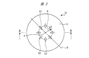
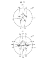
- FIG. 2 is a plan view showing a facing surface of the transport head shown in FIG. 1
- FIG. FIG. 3 is a cross-sectional view taken along the line AA in FIG. 2
- FIG. 4 is a cross-sectional view of the transport head showing a gas layer formed along the facing surface by gas ejected from the ejection port;
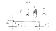
- It is a schematic diagram showing an example of a non-contact conveying device provided with a conveying head.
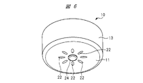
- FIG. 11 is a perspective view showing a transport head of a non-contact transport device according to another embodiment
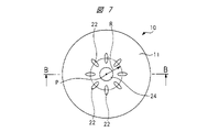
- FIG. 7 is a plan view showing a facing surface of the transport head shown in FIG. 6;
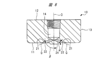
- FIG. 8 is a cross-sectional view taken along the line BB in FIG. 7;
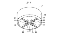
- FIG. 11 is a perspective view showing a transport head of a non-contact transport device according to still another embodiment;
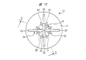
- FIG. 10 is a plan view showing the facing surface of the transport head shown in FIG. 9;
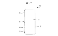
- FIG. 10 is a right side view of FIG. 9;
- 11 is a cross-sectional view taken along line CC in FIG. 10;
- FIG. 8A and 8B are front views showing opposing surfaces of a transport head according to another embodiment;
- the transport head 10 of the non-contact transport apparatus shown in FIGS. 1 to 3 is formed of a block material having a flat opposing surface 11 formed on the front side, and the opposing surface 11 and the back surface 12 on the opposite side are circular. and the outer peripheral surface 13 is cylindrical.
- An air supply port 14 is formed in the transport head 10 , and the air supply port 14 opens to the rear surface 12 of the transport head 10 .
- the transport head 10 is reciprocally movable between, for example, a first position A and a second position B as indicated by an arrow C by a transport mechanism (not shown).
- An air supply joint 15 attached to a screw hole of the air supply port 14 is connected to a supply source 17 of compressed air, that is, a compressed gas, by a gas supply tube 16, and compressed air from the supply source 17 such as a compression pump is supplied.
- a gas supply tube 16 is provided with an on-off valve 18 and a variable throttle valve 19.
- the on-off valve 18 switches between an open state in which the supply source 17 communicates with the gas supply port 14 and a closed state in which the communication is cut off. .
- a variable throttle valve 19 regulates the flow rate of compressed air flowing from the supply source 17 to the air supply port 14 .
- an air supply mechanism for supplying compressed air to the transport head 10 and a transport mechanism for transporting and moving the transport head 10 constitute a non-contact transport device.
- the center position of the opposing surface 11 is the holding center point P, and the central axis O extending axially along the outer peripheral surface 13 passing through the holding center point P is fed.
- An air port 14 is formed, and the central axis O of the air supply port 14 is coaxial with the central axis of the transfer head 10 .
- each ejection path 21 communicates with the air supply port 14 .
- the center line Q of the injection passage 21 extends in the radial direction and is inclined with respect to the facing surface 11 at an angle ⁇ .
- the injection passage 21 has its center line Q inclined with respect to the central axis O of the air supply port 14 at an angle ⁇ .
- the angle ⁇ in the transport head 10 shown in FIG. 3 is 20 degrees and the angle ⁇ is 70 degrees.
- the ejection port 22 of each ejection path 21 opens to the opposing surface 11, and the flat opposing surface 11 is provided with eight ejection ports 22. As shown in FIG. Since the ejection path 21 extends in the radial direction of the conveying head 10 , the ejection port 22 is an elongated hole with the major diameter extending in the radial direction of the facing surface 11 .
- the centers of the major diameters of the eight ejection ports 22 are separated from the holding center point P by the same opening distance of the radius R. Further, the respective ejection ports 22 are arranged on the facing surface 11 with an equal interval of 45 degrees in the circumferential direction.
- each injection passage 21 with respect to the facing surface 11 is set to an acute angle
- the injection port 22 will have an oval shape with a longer diameter in the radial direction.
- Two spouts 22 that are offset by 180 degrees in the circumferential direction are paired apart from each other by the same opening distance R at the position of the same straight line S that passes through the holding center point P and extends radially along the opposing surface 11 . ing. Since the eight ejection ports 22 are arranged at equal intervals of 45 degrees in the circumferential direction, the transport head 10 has four pairs of ejection ports.
- a straight line S connects the central axes of the major diameters of the two ejection ports 22 forming a pair.
- the opening distances R of the two ejection ports 22 forming a pair may be different from each other, or may be the same as shown in FIG.
- FIG. 4 is a cross-sectional view of the transport head 10 showing the gas layer 23 formed along the facing surface 11.
- the air ejected from the ejection port 22 opposes the air.
- a gas layer 23 is formed on the surface 11 .
- the compressed air ejected from the ejection port 22 flows radially outward along the opposing surface 11 because the ejection path 21 is inclined at an acute angle with respect to the opposing surface 11 . Since outside air is sucked from the front of the facing surface 11 toward the gas layer 23, when the facing surface 11 is brought close to the object to be conveyed, the object to be conveyed approaches the facing surface 11 and contacts the facing surface 11. It is held on the facing surface 11 via the gas layer 23 without any pressure.
- the non-contact transport apparatus having the transport head 10 shown in FIGS. 1 to 4 transports the object W from the first position A to the second position B as shown in FIG.
- the transport head 10 is moved toward the transported object W placed at the first position A of the table 31 .
- the opposing surface 11 of the transport head 10 is brought closer to a predetermined distance, the object W to be transported is drawn toward the opposing surface 11, separated from the support base 31 via the gas layer 23, and held on the opposing surface 11 without contact. be done.
- the transport head 10 is horizontally moved above the support table 32 by a transport mechanism (not shown) and then moved downward.
- a transport mechanism not shown
- the facing surface 11 of the transport head 10 is flat rather than concave, the object W to be transferred is held on the flat facing surface 11 via the gas layer 23 . Therefore, the transported object W is transported in a flat state without the surface being curved. As a result, even if the object to be conveyed is a soft food material such as pie crust, the object to be conveyed W will not have a curved or deformed portion such as a protrusion after being conveyed. Work to correct the shape becomes unnecessary.
- the holding center point P is provided at the center position of the facing surface 11.
- the center axis of the cylindrical outer peripheral surface 13 and the holding center point P do not coincide with each other, they may be shifted. good.
- the opposing surface 11 is circular, it may be square, hexagonal, or the like depending on the type of the object to be conveyed. good too.
- the inclination angle ⁇ may be an acute angle, and can be set to various angles according to the type and weight of the object to be conveyed.
- the number of the ejection ports 22 is not limited to eight as described above, and can be set variously according to the type and weight of the object to be conveyed, and may be an even number or an odd number.
- FIGS. 6 to 8 show a transport head 10 according to another embodiment.
- a protruding portion 24 is provided on the facing surface 11 of the transport head 10 so as to be integrated with the transport head 10 .
- the protrusion 24 shown in FIGS. 6 to 8 is circular, and the position of its center point is set at the holding center point P position.
- the outer peripheral surface of the projecting portion 24 is located radially inward of the ejection port 22 .
- the height of the protrusion from the opposing surface 11 should be equal to or greater than the distance between the opposing surface 11 and the transferred object when the transferred object is held.
- the number of ejection paths 21 and ejection ports 22 is eight, as in the above-described transport head 10, and the ejection ports 22 are opened in the facing surface 11 at equal intervals in the circumferential direction.
- FIG. 9 to 12 show a transport head 10 according to still another embodiment.
- a protruding portion 24 consisting of a central protruding portion 26 formed by a single piece is provided integrally with the transport head 10 .
- the number of ejection ports 22 is eight, as in the transport head 10 described above.
- a protruding portion 24 is integrally formed with the conveying head 10 so as to protrude from the facing surface 11 .
- the transported object W comes into contact with the projecting portion 24 when the transported object W is held in a non-contact state with the opposing surface 11 and transported.
- the object W to be conveyed is prevented from shifting along the facing surface 11 due to contact friction with the protrusion 24 during conveyance. Since the facing surface 11 is flat, even if the object W to be conveyed is partially in contact with the protrusion 24 and held, the object W to be conveyed will not be bent or deformed if an appropriate holding force is set.
- the protrusion 24 is integrated with the transport head 10, the transport head 10 can be easily cleaned simply by removing the transport head 10 from the transport mechanism without disassembling the transport head 10, thereby improving maintainability.
- the protrusion 24 is integrally formed with the transport head 10, the protrusion 24 does not come off from the transport head 10, thereby preventing foreign matter from entering the transported object.
- the shape of the protrusions 24 may be square or polygonal, or may be provided with a plurality of protrusions 24, or may be made up of only a plurality of bar-shaped protrusions, depending on the type of the object to be conveyed. Further, the position where the protrusion 24 is provided may be a position that does not interfere with the flow of the air ejected from the ejection port 22, and may be a position according to the type of conveyed article. In order not to hinder the flow of the air ejected from the ejection port 22, at least the straight line connecting the holding center point P and the center of the major axis of the ejection port 22 should be a flat surface without unevenness. As shown in FIG. 10 , the rod-shaped protrusion 25 is provided in a range other than the straight line connecting the holding center point P and the central axis of the major diameter of each ejection port 22 .
- variable throttle valve 19 which is a holding force adjusting means
- the holding force can be set to an appropriate strength according to the type and shape of the object to be transferred. can be done.
- a pressure reducing valve for adjusting the air pressure supplied to the transfer head 10 may be used as the holding force adjusting means.
- FIGS. 13(A) and 13(B) are front views showing the facing surface of the transport head according to another embodiment.
- each ejection port 22 is separated from the holding center point P by the same opening distance R, and the circumference It is shifted at regular intervals of 72 degrees in the direction.
- the number of ejection ports 22 is not limited to the number described above, and can be set to any number as long as it is plural. In order to hold the object to be conveyed well, it is preferable to provide a plurality of ejection ports 22 at regular intervals in the circumferential direction.
- the facing surface 11 is formed with four ejection ports 22a separated by an opening distance R1 from the holding center point P and four ejection ports 22b separated by an opening distance R2. .
- Two ejection ports 22a arranged on the same straight line passing through the holding center point P and displaced by 180 degrees in the circumferential direction form a pair of ejection ports, and are also arranged on the same straight line extending in the radial direction.
- the two ejection ports 22b that are formed and are displaced in the circumferential direction form a pair of ejection ports, and a total of four pairs of ejection ports are provided on the facing surface 11.
- the number of ejection port pairs is not limited to four, and a plurality of pairs can hold an object to be conveyed.
- the facing surface 11 that holds the object W to be conveyed in a non-contact manner is flat, even a soft object to be conveyed will not be deformed when it is held by the conveying head 10 and conveyed. can be suppressed.
- the food can be conveyed without deforming its shape. It is possible to eliminate the need for a process of correcting the shape after transportation.
- soft food is to be conveyed, it is suitable in terms of ease of maintenance and prevention of contamination by foreign matter.
- the objects W to be transferred are not limited to foods, and various products can be transferred as long as they are mass-produced products.
- compressed air is ejected from the ejection port, but other positive pressure gas such as inert gas may be ejected from the ejection port.
- This non-contact transport device is used to transport an object without bringing the transport head into contact with the object.
- it is suitable for conveying soft food materials such as pie dough and bread dough.
Landscapes
- Engineering & Computer Science (AREA)
- Mechanical Engineering (AREA)
- Robotics (AREA)
- Physics & Mathematics (AREA)
- Fluid Mechanics (AREA)
- Manipulator (AREA)
- Container, Conveyance, Adherence, Positioning, Of Wafer (AREA)
- Feeding Of Articles To Conveyors (AREA)
- Delivering By Means Of Belts And Rollers (AREA)
Abstract
Dispositif de transport sans contact possédant une tête de transport (10) dans laquelle est formée une surface de parement (11) plate faisant face à un article transporté. Un orifice d'alimentation en gaz (14) qui est raccordé à une source d'alimentation en gaz comprimé est disposé dans la tête de transport (10). Des ouvertures d'éjection respectives (22) d'une pluralité de passages de jet (21) formés dans la tête de transport (10) en communication avec l'orifice d'alimentation en gaz (14) sont disposées dans des emplacements qui sont éliminés par des distances d'ouverture respectives à partir d'un point (P) central de retenue de la surface de parement (11). Les angles d'inclinaison des passages de jet (21) par rapport à la surface de parement (11) sont conçus sous la forme d'angles aigus. Le gaz comprimé qui est éjecté depuis chacune des ouvertures d'éjection (22) s'écoule le long de la surface de parement (11) et retient l'article transporté sans lui permettre d'entrer en contact avec la surface de parement (11).
Priority Applications (3)
| Application Number | Priority Date | Filing Date | Title |
|---|---|---|---|
| KR1020237013363A KR20230132762A (ko) | 2021-01-22 | 2022-01-19 | 비접촉 반송 장치 |
| CN202280008623.6A CN116670054A (zh) | 2021-01-22 | 2022-01-19 | 非接触输送装置 |
| US18/355,979 US20230365350A1 (en) | 2021-01-22 | 2023-07-20 | Non-Contact Conveyance Device |
Applications Claiming Priority (2)
| Application Number | Priority Date | Filing Date | Title |
|---|---|---|---|
| JP2021008539A JP7576473B2 (ja) | 2021-01-22 | 2021-01-22 | 非接触搬送装置 |
| JP2021-008539 | 2021-01-22 |
Related Child Applications (1)
| Application Number | Title | Priority Date | Filing Date |
|---|---|---|---|
| US18/355,979 Continuation US20230365350A1 (en) | 2021-01-22 | 2023-07-20 | Non-Contact Conveyance Device |
Publications (1)
| Publication Number | Publication Date |
|---|---|
| WO2022158486A1 true WO2022158486A1 (fr) | 2022-07-28 |
Family
ID=82549430
Family Applications (1)
| Application Number | Title | Priority Date | Filing Date |
|---|---|---|---|
| PCT/JP2022/001767 Ceased WO2022158486A1 (fr) | 2021-01-22 | 2022-01-19 | Dispositif de transport sans contact |
Country Status (6)
| Country | Link |
|---|---|
| US (1) | US20230365350A1 (fr) |
| JP (1) | JP7576473B2 (fr) |
| KR (1) | KR20230132762A (fr) |
| CN (1) | CN116670054A (fr) |
| TW (1) | TW202229145A (fr) |
| WO (1) | WO2022158486A1 (fr) |
Families Citing this family (1)
| Publication number | Priority date | Publication date | Assignee | Title |
|---|---|---|---|---|
| CN119768177A (zh) | 2022-07-13 | 2025-04-04 | 国立大学法人大阪大学 | 肿瘤的预防和/或治疗剂 |
Citations (5)
| Publication number | Priority date | Publication date | Assignee | Title |
|---|---|---|---|---|
| JPS5447483A (en) * | 1977-09-21 | 1979-04-14 | Hitachi Ltd | Holder of plate form objects |
| JPS61254437A (ja) * | 1985-04-27 | 1986-11-12 | Fujitsu Ltd | ウエハ−チヤツク |
| JPS61197035U (fr) * | 1985-05-30 | 1986-12-09 | ||
| JP2009032981A (ja) * | 2007-07-27 | 2009-02-12 | Ihi Corp | 非接触搬送装置 |
| JP2019141948A (ja) * | 2018-02-20 | 2019-08-29 | ファナック株式会社 | 吸着パッドおよび吸着パッドの吸着解除方法 |
Family Cites Families (6)
| Publication number | Priority date | Publication date | Assignee | Title |
|---|---|---|---|---|
| JP4358924B2 (ja) * | 1998-11-25 | 2009-11-04 | 株式会社渡辺商行 | 板状基体の収納ユニットおよび収納装置 |
| JP3443375B2 (ja) * | 1999-10-12 | 2003-09-02 | 株式会社コガネイ | 搬送装置 |
| JP2004217252A (ja) * | 2003-01-15 | 2004-08-05 | Koganei Corp | 容器取り出し装置 |
| JP4342331B2 (ja) | 2004-02-09 | 2009-10-14 | 株式会社コガネイ | 非接触搬送装置 |
| JP6402071B2 (ja) * | 2015-06-15 | 2018-10-10 | 株式会社Screenホールディングス | 基板処理装置 |
| DE102015113221A1 (de) * | 2015-08-11 | 2017-02-16 | Weber Maschinenbau Gmbh Breidenbach | Produktgreifer |
-
2021
- 2021-01-22 JP JP2021008539A patent/JP7576473B2/ja active Active
- 2021-11-23 TW TW110143533A patent/TW202229145A/zh unknown
-
2022
- 2022-01-19 KR KR1020237013363A patent/KR20230132762A/ko active Pending
- 2022-01-19 CN CN202280008623.6A patent/CN116670054A/zh active Pending
- 2022-01-19 WO PCT/JP2022/001767 patent/WO2022158486A1/fr not_active Ceased
-
2023
- 2023-07-20 US US18/355,979 patent/US20230365350A1/en active Pending
Patent Citations (5)
| Publication number | Priority date | Publication date | Assignee | Title |
|---|---|---|---|---|
| JPS5447483A (en) * | 1977-09-21 | 1979-04-14 | Hitachi Ltd | Holder of plate form objects |
| JPS61254437A (ja) * | 1985-04-27 | 1986-11-12 | Fujitsu Ltd | ウエハ−チヤツク |
| JPS61197035U (fr) * | 1985-05-30 | 1986-12-09 | ||
| JP2009032981A (ja) * | 2007-07-27 | 2009-02-12 | Ihi Corp | 非接触搬送装置 |
| JP2019141948A (ja) * | 2018-02-20 | 2019-08-29 | ファナック株式会社 | 吸着パッドおよび吸着パッドの吸着解除方法 |
Also Published As
| Publication number | Publication date |
|---|---|
| US20230365350A1 (en) | 2023-11-16 |
| JP7576473B2 (ja) | 2024-10-31 |
| CN116670054A (zh) | 2023-08-29 |
| JP2022112660A (ja) | 2022-08-03 |
| KR20230132762A (ko) | 2023-09-18 |
| TW202229145A (zh) | 2022-08-01 |
Similar Documents
| Publication | Publication Date | Title |
|---|---|---|
| US5695302A (en) | Thrust slot neck-guided air conveyor | |
| WO2022158486A1 (fr) | Dispositif de transport sans contact | |
| WO2005076342A1 (fr) | Dispositif de support sans contact | |
| KR20160093674A (ko) | 유지 장치, 유지 시스템, 제어 방법 및 반송 장치 | |
| JP2009032981A (ja) | 非接触搬送装置 | |
| JP2009028862A (ja) | 非接触搬送装置 | |
| KR102315301B1 (ko) | 반송 패드 및 웨이퍼의 반송 방법 | |
| WO2019065424A1 (fr) | Goutteur et tube d'irrigation goutte à goutte | |
| KR101261313B1 (ko) | 평판 이송물 정렬픽업 이송장치 | |
| CN108349617A (zh) | 用于标签印模的印模底座和用于加标签的装置和方法 | |
| CA2430876A1 (fr) | Procede de traitement de produits d'imprimerie | |
| JP3383739B2 (ja) | ワーク保持装置 | |
| JP5384305B2 (ja) | ワーク搬送装置 | |
| JP2016030234A (ja) | 成形品検査機用排出装置 | |
| US7681711B2 (en) | Push device for transferring glass articles | |
| JP3443375B2 (ja) | 搬送装置 | |
| TWI831852B (zh) | 流體輸送系統及電鍍工件的方法 | |
| US5951211A (en) | Air conveyor having transitional section | |
| JP2009272337A (ja) | 非接触搬送装置及びベルヌーイチャック | |
| JP2002066974A (ja) | 物品を把持するための方法および装置 | |
| JPH0641938Y2 (ja) | 小径円筒物品の搬送装置 | |
| EP4190532B1 (fr) | Dispositif de préhension pour le support et le déplacement de préformes | |
| KR101365015B1 (ko) | 슬리브 이송 장치 및 이송 공정 | |
| GB2584069A (en) | Flow gripper | |
| JPH04282850A (ja) | 試料保持装置 |
Legal Events
| Date | Code | Title | Description |
|---|---|---|---|
| 121 | Ep: the epo has been informed by wipo that ep was designated in this application |
Ref document number: 22742608 Country of ref document: EP Kind code of ref document: A1 |
|
| WWE | Wipo information: entry into national phase |
Ref document number: 202280008623.6 Country of ref document: CN |
|
| NENP | Non-entry into the national phase |
Ref country code: DE |
|
| 122 | Ep: pct application non-entry in european phase |
Ref document number: 22742608 Country of ref document: EP Kind code of ref document: A1 |