WO2022158486A1 - 非接触搬送装置 - Google Patents
非接触搬送装置 Download PDFInfo
- Publication number
- WO2022158486A1 WO2022158486A1 PCT/JP2022/001767 JP2022001767W WO2022158486A1 WO 2022158486 A1 WO2022158486 A1 WO 2022158486A1 JP 2022001767 W JP2022001767 W JP 2022001767W WO 2022158486 A1 WO2022158486 A1 WO 2022158486A1
- Authority
- WO
- WIPO (PCT)
- Prior art keywords
- contact
- facing surface
- ejection
- conveying device
- head
- Prior art date
- Legal status (The legal status is an assumption and is not a legal conclusion. Google has not performed a legal analysis and makes no representation as to the accuracy of the status listed.)
- Ceased
Links
Images


Classifications
-
- B—PERFORMING OPERATIONS; TRANSPORTING
- B65—CONVEYING; PACKING; STORING; HANDLING THIN OR FILAMENTARY MATERIAL
- B65G—TRANSPORT OR STORAGE DEVICES, e.g. CONVEYORS FOR LOADING OR TIPPING, SHOP CONVEYOR SYSTEMS OR PNEUMATIC TUBE CONVEYORS
- B65G51/00—Conveying articles through pipes or tubes by fluid flow or pressure; Conveying articles over a flat surface, e.g. the base of a trough, by jets located in the surface
- B65G51/02—Directly conveying the articles, e.g. slips, sheets, stockings, containers or workpieces, by flowing gases
- B65G51/03—Directly conveying the articles, e.g. slips, sheets, stockings, containers or workpieces, by flowing gases over a flat surface or in troughs
-
- B—PERFORMING OPERATIONS; TRANSPORTING
- B65—CONVEYING; PACKING; STORING; HANDLING THIN OR FILAMENTARY MATERIAL
- B65G—TRANSPORT OR STORAGE DEVICES, e.g. CONVEYORS FOR LOADING OR TIPPING, SHOP CONVEYOR SYSTEMS OR PNEUMATIC TUBE CONVEYORS
- B65G47/00—Article or material-handling devices associated with conveyors; Methods employing such devices
- B65G47/74—Feeding, transfer, or discharging devices of particular kinds or types
- B65G47/90—Devices for picking-up and depositing articles or materials
- B65G47/91—Devices for picking-up and depositing articles or materials incorporating pneumatic, e.g. suction, grippers
- B65G47/911—Devices for picking-up and depositing articles or materials incorporating pneumatic, e.g. suction, grippers with air blasts producing partial vacuum
-
- B—PERFORMING OPERATIONS; TRANSPORTING
- B25—HAND TOOLS; PORTABLE POWER-DRIVEN TOOLS; MANIPULATORS
- B25J—MANIPULATORS; CHAMBERS PROVIDED WITH MANIPULATION DEVICES
- B25J15/00—Gripping heads and other end effectors
- B25J15/06—Gripping heads and other end effectors with vacuum or magnetic holding means
- B25J15/0616—Gripping heads and other end effectors with vacuum or magnetic holding means with vacuum
-
- B—PERFORMING OPERATIONS; TRANSPORTING
- B65—CONVEYING; PACKING; STORING; HANDLING THIN OR FILAMENTARY MATERIAL
- B65G—TRANSPORT OR STORAGE DEVICES, e.g. CONVEYORS FOR LOADING OR TIPPING, SHOP CONVEYOR SYSTEMS OR PNEUMATIC TUBE CONVEYORS
- B65G2201/00—Indexing codes relating to handling devices, e.g. conveyors, characterised by the type of product or load being conveyed or handled
- B65G2201/02—Articles
- B65G2201/0202—Agricultural and processed food products
Definitions
- the present invention relates to a non-contact transport device that holds and transports an object to be transported in a non-contact manner.
- Non-contact transport devices are used not only for transporting machine parts, but also for transporting food as objects to be transported.
- a conventional non-contact conveying device has a form comprising a conveying head having a concave portion formed on the tip surface thereof and a disk-shaped nozzle provided at the center of the concave portion. .
- the concave portion has an annular holding surface and a gas guide surface that gently curves from the center toward the holding surface, and the gas ejected from the slit between the nozzle and the tip surface of the transport head is , flows radially outward after reaching the holding surface along the gas guide surface. Since the front of the tip surface of the transport head is in a negative pressure state due to the airflow directed toward the tip surface, when the object to be transported is placed in front of the transport head, the object to be transported is attracted to the transport head by the negative pressure and approaches.
- the air current flowing along the holding surface prevents the transported object from coming into direct contact with the transporting head, and the transported object is held by suction in a non-contact state.
- the transported object can be transported by moving the transport head.
- the soft food materials When conveying soft food materials such as pie dough, bread dough, and gyoza wrappers among the objects to be conveyed by a conventional non-contact conveying device, the soft food materials are conveyed on the curved gas guide surface of the conveying head during conveyance. , forming an annular protrusion on the surface of the food material. If an annular projection is formed on the surface of the food material, it may be necessary to correct the shape after transportation.
- An object of the present invention is to provide a non-contact conveying device capable of conveying even a soft conveyed object without deforming the conveyed object.
- a non-contact conveying apparatus of the present invention is a non-contact conveying apparatus that conveys an object to be conveyed while holding it in a non-contact manner, and has a conveying head formed with a flat facing surface facing the object to be conveyed.
- An air supply port connected to a gas supply source is provided in the conveying head, and each ejection port of a plurality of ejection passages formed in the conveying head in communication with the air supply port is arranged at the holding center of the opposing surface.
- the nozzles are provided at positions separated from each other by an opening distance, and the angle of inclination of the jet passages with respect to the facing surface is set at an acute angle, and the compressed gas jetted from each of the jet outlets flows along the facing surface to carry the object. is held without contacting the opposing surface.
- the opposing surface that holds the transported object in a non-contact manner is flat, even a soft transported object can be restrained from being deformed when it is held by the transport head and transported.
- FIG. 1 is a perspective view showing a transport head of a non-contact transport device according to one embodiment
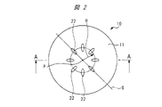
- FIG. 2 is a plan view showing a facing surface of the transport head shown in FIG. 1
- FIG. FIG. 3 is a cross-sectional view taken along the line AA in FIG. 2
- FIG. 4 is a cross-sectional view of the transport head showing a gas layer formed along the facing surface by gas ejected from the ejection port;
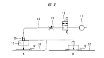
- It is a schematic diagram showing an example of a non-contact conveying device provided with a conveying head.
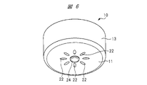
- FIG. 11 is a perspective view showing a transport head of a non-contact transport device according to another embodiment
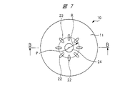
- FIG. 7 is a plan view showing a facing surface of the transport head shown in FIG. 6;
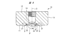
- FIG. 8 is a cross-sectional view taken along the line BB in FIG. 7;
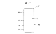
- FIG. 11 is a perspective view showing a transport head of a non-contact transport device according to still another embodiment;
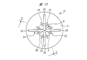
- FIG. 10 is a plan view showing the facing surface of the transport head shown in FIG. 9;
- FIG. 10 is a right side view of FIG. 9;
- 11 is a cross-sectional view taken along line CC in FIG. 10;
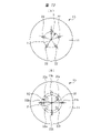
- FIG. 8A and 8B are front views showing opposing surfaces of a transport head according to another embodiment;
- the transport head 10 of the non-contact transport apparatus shown in FIGS. 1 to 3 is formed of a block material having a flat opposing surface 11 formed on the front side, and the opposing surface 11 and the back surface 12 on the opposite side are circular. and the outer peripheral surface 13 is cylindrical.
- An air supply port 14 is formed in the transport head 10 , and the air supply port 14 opens to the rear surface 12 of the transport head 10 .
- the transport head 10 is reciprocally movable between, for example, a first position A and a second position B as indicated by an arrow C by a transport mechanism (not shown).
- An air supply joint 15 attached to a screw hole of the air supply port 14 is connected to a supply source 17 of compressed air, that is, a compressed gas, by a gas supply tube 16, and compressed air from the supply source 17 such as a compression pump is supplied.
- a gas supply tube 16 is provided with an on-off valve 18 and a variable throttle valve 19.
- the on-off valve 18 switches between an open state in which the supply source 17 communicates with the gas supply port 14 and a closed state in which the communication is cut off. .
- a variable throttle valve 19 regulates the flow rate of compressed air flowing from the supply source 17 to the air supply port 14 .
- an air supply mechanism for supplying compressed air to the transport head 10 and a transport mechanism for transporting and moving the transport head 10 constitute a non-contact transport device.
- the center position of the opposing surface 11 is the holding center point P, and the central axis O extending axially along the outer peripheral surface 13 passing through the holding center point P is fed.
- An air port 14 is formed, and the central axis O of the air supply port 14 is coaxial with the central axis of the transfer head 10 .
- each ejection path 21 communicates with the air supply port 14 .
- the center line Q of the injection passage 21 extends in the radial direction and is inclined with respect to the facing surface 11 at an angle ⁇ .
- the injection passage 21 has its center line Q inclined with respect to the central axis O of the air supply port 14 at an angle ⁇ .
- the angle ⁇ in the transport head 10 shown in FIG. 3 is 20 degrees and the angle ⁇ is 70 degrees.
- the ejection port 22 of each ejection path 21 opens to the opposing surface 11, and the flat opposing surface 11 is provided with eight ejection ports 22. As shown in FIG. Since the ejection path 21 extends in the radial direction of the conveying head 10 , the ejection port 22 is an elongated hole with the major diameter extending in the radial direction of the facing surface 11 .
- the centers of the major diameters of the eight ejection ports 22 are separated from the holding center point P by the same opening distance of the radius R. Further, the respective ejection ports 22 are arranged on the facing surface 11 with an equal interval of 45 degrees in the circumferential direction.
- each injection passage 21 with respect to the facing surface 11 is set to an acute angle
- the injection port 22 will have an oval shape with a longer diameter in the radial direction.
- Two spouts 22 that are offset by 180 degrees in the circumferential direction are paired apart from each other by the same opening distance R at the position of the same straight line S that passes through the holding center point P and extends radially along the opposing surface 11 . ing. Since the eight ejection ports 22 are arranged at equal intervals of 45 degrees in the circumferential direction, the transport head 10 has four pairs of ejection ports.
- a straight line S connects the central axes of the major diameters of the two ejection ports 22 forming a pair.
- the opening distances R of the two ejection ports 22 forming a pair may be different from each other, or may be the same as shown in FIG.
- FIG. 4 is a cross-sectional view of the transport head 10 showing the gas layer 23 formed along the facing surface 11.
- the air ejected from the ejection port 22 opposes the air.
- a gas layer 23 is formed on the surface 11 .
- the compressed air ejected from the ejection port 22 flows radially outward along the opposing surface 11 because the ejection path 21 is inclined at an acute angle with respect to the opposing surface 11 . Since outside air is sucked from the front of the facing surface 11 toward the gas layer 23, when the facing surface 11 is brought close to the object to be conveyed, the object to be conveyed approaches the facing surface 11 and contacts the facing surface 11. It is held on the facing surface 11 via the gas layer 23 without any pressure.
- the non-contact transport apparatus having the transport head 10 shown in FIGS. 1 to 4 transports the object W from the first position A to the second position B as shown in FIG.
- the transport head 10 is moved toward the transported object W placed at the first position A of the table 31 .
- the opposing surface 11 of the transport head 10 is brought closer to a predetermined distance, the object W to be transported is drawn toward the opposing surface 11, separated from the support base 31 via the gas layer 23, and held on the opposing surface 11 without contact. be done.
- the transport head 10 is horizontally moved above the support table 32 by a transport mechanism (not shown) and then moved downward.
- a transport mechanism not shown
- the facing surface 11 of the transport head 10 is flat rather than concave, the object W to be transferred is held on the flat facing surface 11 via the gas layer 23 . Therefore, the transported object W is transported in a flat state without the surface being curved. As a result, even if the object to be conveyed is a soft food material such as pie crust, the object to be conveyed W will not have a curved or deformed portion such as a protrusion after being conveyed. Work to correct the shape becomes unnecessary.
- the holding center point P is provided at the center position of the facing surface 11.
- the center axis of the cylindrical outer peripheral surface 13 and the holding center point P do not coincide with each other, they may be shifted. good.
- the opposing surface 11 is circular, it may be square, hexagonal, or the like depending on the type of the object to be conveyed. good too.
- the inclination angle ⁇ may be an acute angle, and can be set to various angles according to the type and weight of the object to be conveyed.
- the number of the ejection ports 22 is not limited to eight as described above, and can be set variously according to the type and weight of the object to be conveyed, and may be an even number or an odd number.
- FIGS. 6 to 8 show a transport head 10 according to another embodiment.
- a protruding portion 24 is provided on the facing surface 11 of the transport head 10 so as to be integrated with the transport head 10 .
- the protrusion 24 shown in FIGS. 6 to 8 is circular, and the position of its center point is set at the holding center point P position.
- the outer peripheral surface of the projecting portion 24 is located radially inward of the ejection port 22 .
- the height of the protrusion from the opposing surface 11 should be equal to or greater than the distance between the opposing surface 11 and the transferred object when the transferred object is held.
- the number of ejection paths 21 and ejection ports 22 is eight, as in the above-described transport head 10, and the ejection ports 22 are opened in the facing surface 11 at equal intervals in the circumferential direction.
- FIG. 9 to 12 show a transport head 10 according to still another embodiment.
- a protruding portion 24 consisting of a central protruding portion 26 formed by a single piece is provided integrally with the transport head 10 .
- the number of ejection ports 22 is eight, as in the transport head 10 described above.
- a protruding portion 24 is integrally formed with the conveying head 10 so as to protrude from the facing surface 11 .
- the transported object W comes into contact with the projecting portion 24 when the transported object W is held in a non-contact state with the opposing surface 11 and transported.
- the object W to be conveyed is prevented from shifting along the facing surface 11 due to contact friction with the protrusion 24 during conveyance. Since the facing surface 11 is flat, even if the object W to be conveyed is partially in contact with the protrusion 24 and held, the object W to be conveyed will not be bent or deformed if an appropriate holding force is set.
- the protrusion 24 is integrated with the transport head 10, the transport head 10 can be easily cleaned simply by removing the transport head 10 from the transport mechanism without disassembling the transport head 10, thereby improving maintainability.
- the protrusion 24 is integrally formed with the transport head 10, the protrusion 24 does not come off from the transport head 10, thereby preventing foreign matter from entering the transported object.
- the shape of the protrusions 24 may be square or polygonal, or may be provided with a plurality of protrusions 24, or may be made up of only a plurality of bar-shaped protrusions, depending on the type of the object to be conveyed. Further, the position where the protrusion 24 is provided may be a position that does not interfere with the flow of the air ejected from the ejection port 22, and may be a position according to the type of conveyed article. In order not to hinder the flow of the air ejected from the ejection port 22, at least the straight line connecting the holding center point P and the center of the major axis of the ejection port 22 should be a flat surface without unevenness. As shown in FIG. 10 , the rod-shaped protrusion 25 is provided in a range other than the straight line connecting the holding center point P and the central axis of the major diameter of each ejection port 22 .
- variable throttle valve 19 which is a holding force adjusting means
- the holding force can be set to an appropriate strength according to the type and shape of the object to be transferred. can be done.
- a pressure reducing valve for adjusting the air pressure supplied to the transfer head 10 may be used as the holding force adjusting means.
- FIGS. 13(A) and 13(B) are front views showing the facing surface of the transport head according to another embodiment.
- each ejection port 22 is separated from the holding center point P by the same opening distance R, and the circumference It is shifted at regular intervals of 72 degrees in the direction.
- the number of ejection ports 22 is not limited to the number described above, and can be set to any number as long as it is plural. In order to hold the object to be conveyed well, it is preferable to provide a plurality of ejection ports 22 at regular intervals in the circumferential direction.
- the facing surface 11 is formed with four ejection ports 22a separated by an opening distance R1 from the holding center point P and four ejection ports 22b separated by an opening distance R2. .
- Two ejection ports 22a arranged on the same straight line passing through the holding center point P and displaced by 180 degrees in the circumferential direction form a pair of ejection ports, and are also arranged on the same straight line extending in the radial direction.
- the two ejection ports 22b that are formed and are displaced in the circumferential direction form a pair of ejection ports, and a total of four pairs of ejection ports are provided on the facing surface 11.
- the number of ejection port pairs is not limited to four, and a plurality of pairs can hold an object to be conveyed.
- the facing surface 11 that holds the object W to be conveyed in a non-contact manner is flat, even a soft object to be conveyed will not be deformed when it is held by the conveying head 10 and conveyed. can be suppressed.
- the food can be conveyed without deforming its shape. It is possible to eliminate the need for a process of correcting the shape after transportation.
- soft food is to be conveyed, it is suitable in terms of ease of maintenance and prevention of contamination by foreign matter.
- the objects W to be transferred are not limited to foods, and various products can be transferred as long as they are mass-produced products.
- compressed air is ejected from the ejection port, but other positive pressure gas such as inert gas may be ejected from the ejection port.
- This non-contact transport device is used to transport an object without bringing the transport head into contact with the object.
- it is suitable for conveying soft food materials such as pie dough and bread dough.
Landscapes
- Engineering & Computer Science (AREA)
- Mechanical Engineering (AREA)
- Robotics (AREA)
- Physics & Mathematics (AREA)
- Fluid Mechanics (AREA)
- Manipulator (AREA)
- Container, Conveyance, Adherence, Positioning, Of Wafer (AREA)
- Feeding Of Articles To Conveyors (AREA)
- Delivering By Means Of Belts And Rollers (AREA)
Abstract
非接触搬送装置は、被搬送物に対向する平坦な対向面11が形成された搬送ヘッド10を有し、圧縮気体の供給源に接続される給気ポート14を前記搬送ヘッド10に設け、前記給気ポート14に連通して前記搬送ヘッド10に形成された複数の噴射路21のそれぞれの噴出口22を、前記対向面11の保持中心点Pからそれぞれ開口距離だけ離した位置に設け、噴射路21の前記対向面11に対する傾斜角度を鋭角に設定し、それぞれの噴出口22から噴出した圧縮気体が前記対向面11に沿って流れて被搬送物を対向面11に接触させることなく保持する。
Description
本発明は被搬送物を非接触で保持して搬送する非接触搬送装置に関する。
非接触搬送装置は、機械部品のみならず、食品を被搬送物として搬送するために使用されている。従来の非接触搬送装置としては、特許文献1に記載されるように、先端面に凹部が形成された搬送ヘッドと、凹部の中心に設けられた円板形状のノズルとを備えた形態がある。
凹部は環状の保持面と中心部からこの保持面に向けてなだらかに湾曲して連なる気体案内面とを有しており、ノズルと搬送ヘッドの先端面との間のスリットから噴出された気体は、気体案内面に沿って保持面まで到達した後に径方向外方に流れる。搬送ヘッドの先端面前方は先端面に向かう気流により負圧状態となるので、搬送ヘッドの前方に被搬送物が配置されると、被搬送物は負圧によって搬送ヘッドに吸い寄せられて接近する。
保持面にはこれに沿って流れる気流により被搬送物が直接接触することが防止され、被搬送物は搬送ヘッドに非接触状態で吸引保持される。搬送ヘッドを移動させることにより被搬送物を搬送することができる。
被搬送物のうちパイ生地やパン生地、餃子の皮のような軟質な食品材料を従来の非接触搬送装置により搬送する場合には、軟質の食品材料が搬送時に搬送ヘッドの湾曲した気体案内面に沿って変形し、食品材料の表面に環状の突起が形成される。食品材料の表面に環状の突起が形成されると、搬送終了後に形状の修正が必要になる場合がある。
本発明の目的は、軟らかな被搬送物であっても、被搬送物を変形させることなく、搬送し得る非接触搬送装置を提供することにある。
本発明の非接触搬送装置は、被搬送物を非接触で保持しながら搬送する非接触搬送装置であって、被搬送物に対向する平坦な対向面が形成された搬送ヘッドを有し、圧縮気体の供給源に接続される給気ポートを前記搬送ヘッドに設け、前記給気ポートに連通して前記搬送ヘッドに形成された複数の噴射路のそれぞれの噴出口を、前記対向面の保持中心点からそれぞれ開口距離だけ離した位置に設け、前記噴射路の前記対向面に対する傾斜角度を鋭角に設定し、それぞれの前記噴出口から噴出した圧縮気体が前記対向面に沿って流れて被搬送物を対向面に接触させることなく保持する。
被搬送物を非接触で保持する対向面は平坦となっているので、軟らかな被搬送物であっても搬送ヘッドに保持されて搬送されるときに、変形することを抑制することができる。
以下、本発明の実施の形態を図面に基づいて詳細に説明する。実施の形態を示す図面においては、共通性を有する部材には同一の符号が付されている。
図1~図3に示す非接触搬送装置の搬送ヘッド10は、正面側に平坦な対向面11が形成されたブロック材により形成されており、対向面11とこれの反対側の背面12は円形であり、外周面13は円筒形状である。搬送ヘッド10には給気ポート14が形成されており、給気ポート14は搬送ヘッド10の背面12に開口している。
搬送ヘッド10は、図5に示されるように、例えば、第1の位置Aと第2の位置Bとの間を図示しない搬送機構により矢印Cで示されるように往復移動自在である。給気ポート14のねじ孔に取り付けられる給気継手15は、気体供給チューブ16により圧縮空気つまり圧縮気体の供給源17に接続されており、圧縮ポンプ等の供給源17からの圧縮空気が給気ポート14に供給される。気体供給チューブ16には、開閉弁18と可変絞り弁19とが設けられており、開閉弁18は供給源17を給気ポート14に連通させる開状態と、連通を遮断する閉状態とに切り換える。可変絞り弁19は供給源17から給気ポート14に流れる圧縮空気の流量を調整する。図5に示すように、搬送ヘッド10に圧縮空気を供給する給気機構と、搬送ヘッド10を搬送移動する搬送機構とにより、非接触搬送装置が構成される。
図2および図3に示されるように、対向面11の中心位置は保持中心点Pであり、この保持中心点Pを貫通し外周面13に沿って軸方向に延びる中心軸Oの位置に給気ポート14が形成され、給気ポート14の中心軸Oは搬送ヘッド10の中心軸と同軸である。
8つの噴射路21が搬送ヘッド10に形成されており、それぞれの噴射路21は給気ポート14に連通している。噴射路21の中心線Qは径方向に延びるとともに対向面11に角度αの傾斜角度で傾斜している。噴射路21は、その中心線Qが給気ポート14の中心軸Oに対して角度βの傾斜角度で傾斜している。図3に示される搬送ヘッド10における角度αは20度であり、角度βは70度である。それぞれの噴射路21の噴出口22が対向面11に開口しており、平坦な対向面11には8つの噴出口22が設けられている。噴射路21が搬送ヘッド10の半径方向に延びているので、噴出口22は対向面11の半径方向が長径となった長孔である。
図2に示されるように、8つの噴出口22の長径の中心は、保持中心点Pから同一の半径Rの開口距離離れている。さらに、それぞれの噴出口22は円周方向に45度ずつ等間隔ずれて対向面11に配置されている。
それぞれの噴射路21の対向面11に対する傾斜角度を鋭角に設定すると、噴出口22は半径方向に長径となった長円形状になる。円周方向に180度ずれた2つの噴出口22は、保持中心点Pを通過して対向面11に沿って半径方向に延びる同一直線Sの位置に同一の開口距離Rだけ離れて対となっている。8つの噴出口22が円周方向に45度ずつ等間隔に配置されているので、搬送ヘッド10は4対の噴出口対を備えている。直線Sは、対をなす2つの噴出口22の長径の中心軸を結んでいる。対をなす2つの噴出口22の開口距離Rとしては、相互に相違させてもよく、図2に示すように同一としてもよい。
図4は対向面11に沿って形成された気体層23を示す搬送ヘッド10の断面図であり、給気ポート14に供給源17から圧縮空気を供給すると、噴出口22から噴出した空気により対向面11に気体層23が形成される。噴出口22から噴出した圧縮空気は、噴射路21が対向面11に対して鋭角で傾斜しているので、対向面11に沿って径方向外方に流れる。気体層23に向けて対向面11の前方から外気が吸引されるので、被搬送物に対向面11を接近させると、被搬送物は対向面11に向けて接近し、対向面11に接触することなく、気体層23を介して対向面11に保持される。
図1~図4に示した搬送ヘッド10を備えた非接触搬送装置により、図5のように、第1の位置Aから第2の位置Bに被搬送物Wを搬送する場合には、支持台31の第1の位置Aに配置された被搬送物Wに向けて搬送ヘッド10を接近させる。所定の距離まで搬送ヘッド10の対向面11を接近させると、被搬送物Wは対向面11に向けて引き寄せられ、気体層23を介して支持台31から離れて対向面11に非接触で保持される。
この状態のもとで、搬送ヘッド10は、図示しない搬送機構により、支持台32の上方にまで水平移動した後に下降移動する。被搬送物Wが第2の位置Bの支持台32に接触した状態のもとで、給気ポート14に対する圧縮空気の供給を停止すると、被搬送物Wは支持台31の第2の位置Bに配置される。
搬送ヘッド10の対向面11は凹面となっておらず平坦となっているので、被搬送物Wは平坦な対向面11に気体層23を介して保持される。したがって、被搬送物Wは表面が湾曲することなく、平坦な状態で搬送される。これにより、パイ生地のような軟質な食品材料を被搬送物としても、搬送終了後に被搬送物Wに、突起等の湾曲変形した部位が形成されることがなくなり、搬送終了後に被搬送物の形状を修正する作業が不要となる。
上述の搬送ヘッド10においては、保持中心点Pが対向面11の中心位置に設けられているが、円筒形状の外周面13の中心軸と保持中心点Pとを一致させることなく、ずらしてもよい。また、対向面11は円形であるが、被搬送物の種類に応じて、四角形や六角形等としてもよく、その場合においても、対向面の中心位置と保持中心点Pの位置とをずらしてもよい。
傾斜角度αは鋭角であればよく、被搬送物の種類や重量等に応じて種々の角度に設定することができる。また、噴出口22の数は、上述した8つに限られることなく、被搬送物の種類や重量等に応じて複数であれば種々に設定することができ、偶数個でも奇数個でもよい。
図6~図8は、他の実施の形態である搬送ヘッド10を示す。この搬送ヘッド10の対向面11には突起部24が搬送ヘッド10と一体になって設けられている。図6~8に示される突起部24は円形であり、その中心点の位置は保持中心点Pの位置に設定されている。突起部24の外周面は噴出口22よりも径方向内側に位置している。対向面11からの突出高さは、被搬送物を保持する時の対向面11と被搬送物の距離以上の高さがあればよい。噴射路21および噴出口22の数は、上述した搬送ヘッド10と同様に8つであり、噴出口22は円周方向に等間隔毎に対向面11に開口している。
図9~図12は、さらに他の実施の形態である搬送ヘッド10を示す。この搬送ヘッド10の対向面11には、対向面11の保持中心点Pから径方向に延びる4本の棒状突起部25と、それぞれの棒状突起部25の径方向内方端部が一体となって形成する中心突起部26からなる突起部24が搬送ヘッド10と一体になって設けられている。
噴出口22の数は、上述した搬送ヘッド10と同様に8つであり、円周方向の隣り合う2つの噴出口22の間に位置させて、それぞれの棒状突起部25と中心突起部26からなる突起部24が搬送ヘッド10と一体になって対向面11に突出して設けられている。
このように、突起部24を設けると、被搬送物Wを対向面11に非接触状態で保持して搬送するときに、被搬送物Wが突起部24に接触する。これにより、被搬送物Wは搬送時における突起部24との接触摩擦により、対向面11に対してこれに沿う方向にずれ移動することが抑制される。対向面11は平坦となっているので、被搬送物Wが部分的に突起部24に接触した状態で保持しても、適切な保持力に設定すれば被搬送物Wは湾曲変形しない。さらに、突起部24を、搬送ヘッド10と一体にすると、搬送ヘッド10を分解することなく、搬送ヘッド10を搬送機構から取り外すだけで容易に洗浄することができ、メンテナンス性が向上する。また、突起部24が搬送ヘッド10と一体に構成されているので、搬送ヘッド10から突起部24が外れることがないので、被搬送物への異物の混入を防止できる。
突起部24の形状は、被搬送物の種類に応じて四角形や多角形としたり、複数の突起部24を設けたり、複数の棒状突起部のみからなる形状としたりしても良い。また、突起部24を設ける位置は、噴出口22から噴出した空気の流れを妨げない位置であれば、搬送物の種類に応じた位置とすればよい。噴出口22から噴出した空気の流れを妨げないためには、少なくとも保持中心点Pと噴出口22の長径の中心を結ぶ直線上を凹凸が存在しない平坦面とする必要がある。図10に示されるように、棒状突起部25は、保持中心点Pと各噴出口22の長径の中心軸を結ぶ直線上以外の範囲に設けられている。
また、保持力調整手段である可変絞り弁19によって搬送ヘッド10に供給する圧縮空気の流量を調節することで、被搬送物の種類や形状に応じて保持力を適切な強さに設定することができる。可変絞り弁19に替えて、搬送ヘッド10に供給する空気圧を調整する減圧弁を保持力調整手段としても良い。
図13(A)、(B)はそれぞれ他の実施の形態である搬送ヘッドの対向面を示す正面図である。
図13(A)に示す搬送ヘッド10においては、対向面11に5つの噴出口22が形成されており、それぞれの噴出口22は保持中心点Pから同一の開口距離R離れており、円周方向に72度ずつ一定間隔にずれている。このように、噴出口22の数は上述した数に限られることなく、複数個であれば、任意の数に設定することができる。被搬送物を良好に保持するには、複数の噴出口22を円周方向に一定間隔に設けることが好ましい。
図13(B)に示す搬送ヘッド10においては、保持中心点Pから開口距離R1離れた4つの噴出口22aと、開口距離R2離れた4つの噴出口22bとが対向面11に形成されている。保持中心点Pを通る同一の直線の位置に配置されて円周方向に180度ずれている2つの噴出口22aが噴出口対を構成し、同様に径方向に延びる同一の直線の位置に配置されて円周方向にずれている2つの噴出口22bが噴出口対を構成しており、合計4対の噴出口対が対向面11に設けられている。噴出口対の数としては、4対に限られず、複数対であれば、被搬送物を保持することができる。
上述のように、被搬送物Wを非接触で保持する対向面11は平坦となっているので、軟らかな被搬送物であっても搬送ヘッド10に保持されて搬送されるときに変形することを抑制することができる。これにより、パン生地やパイ生地、餃子の皮のような軟らかな食品を搬送する場合であっても、形状を変形させることなく搬送できる。搬送後に形状を修正する工程を不要とすることができる。特に、軟らかな食品を被搬送物とする場合は、メンテナンス性や異物の混入を防止できる点において好適である。もちろん、被搬送物Wは食品に限られず、量産品であれば、種々の製品を被搬送物とすることができる。
本発明は前記実施の形態に限定されるものではなく、その要旨を逸脱しない範囲で種々変更可能である。例えば、上述した実施の形態においては、噴出口から圧縮空気を噴出するようにしているが、不活性ガスなどの他の正圧気体を噴出口から噴出するようにしてもよい。
この非接触搬送装置は、搬送ヘッドを被搬送物に接触させることなく、搬送するために使用される。特に、パイ生地やパン生地のように軟質な食品材料を搬送する場合に好適である。
Claims (9)
- 被搬送物を非接触で保持しながら搬送する非接触搬送装置であって、
被搬送物に対向する平坦な対向面が形成された搬送ヘッドを有し、
圧縮気体の供給源に接続される給気ポートを前記搬送ヘッドに設け、
前記給気ポートに連通して前記搬送ヘッドに形成された複数の噴射路のそれぞれの噴出口を、前記対向面の保持中心点からそれぞれ開口距離だけ離した位置に設け、
前記噴射路の前記対向面に対する傾斜角度を鋭角に設定し、
それぞれの前記噴出口から噴出した圧縮気体が前記対向面に沿って流れて被搬送物を対向面に接触させることなく保持する、非接触搬送装置。 - 請求項1記載の非接触搬送装置において、
複数の前記噴出口は、前記保持中心点を通過して前記対向面に沿って延びる同一直線の位置にそれぞれ開口距離だけ離れた2つの前記噴出口により対をなす噴出口対を複数有する、非接触搬送装置。 - 請求項2記載の非接触搬送装置において、
前記噴出口対を形成する2つの前記噴出口は、前記保持中心点からそれぞれ同一の開口距離だけ離れている、非接触搬送装置。 - 請求項1~3項のいずれか1項に記載の非接触搬送装置において、
前記噴出口を前記対向面の円周方向に一定間隔ずらして設けた、非接触搬送装置。 - 請求項1~4のいずれか1項に記載の非接触搬送装置において、
それぞれの前記噴出口は前記保持中心点から同一の開口距離の位置に設けられている、非接触搬送装置。 - 請求項1~5のいずれか1項に記載の非接触搬送装置において、
前記対向面より突出し被搬送物の搬送時に被搬送物と接触する突起部を、保持中心点と各噴出口の長径の中心を結ぶ直線上以外の範囲に設けた、非接触搬送装置。 - 請求項6記載の非接触搬送装置において、
前記突起部を、前記噴出口よりも径方向内側に位置させた、非接触搬送装置。 - 請求項6記載の非接触搬送装置において、
前記突起部を、前記対向面の径方向に延びる棒状突起部とした、非接触搬送装置。 - 請求項8に記載の非接触搬送装置において、
前記突起部は、前記棒状突起部と、前記棒状突起部の径方向内方端部が一体となって形成する中心突起部からなる非接触搬送装置。
Priority Applications (3)
| Application Number | Priority Date | Filing Date | Title |
|---|---|---|---|
| CN202280008623.6A CN116670054A (zh) | 2021-01-22 | 2022-01-19 | 非接触输送装置 |
| KR1020237013363A KR20230132762A (ko) | 2021-01-22 | 2022-01-19 | 비접촉 반송 장치 |
| US18/355,979 US20230365350A1 (en) | 2021-01-22 | 2023-07-20 | Non-Contact Conveyance Device |
Applications Claiming Priority (2)
| Application Number | Priority Date | Filing Date | Title |
|---|---|---|---|
| JP2021008539A JP7576473B2 (ja) | 2021-01-22 | 2021-01-22 | 非接触搬送装置 |
| JP2021-008539 | 2021-01-22 |
Related Child Applications (1)
| Application Number | Title | Priority Date | Filing Date |
|---|---|---|---|
| US18/355,979 Continuation US20230365350A1 (en) | 2021-01-22 | 2023-07-20 | Non-Contact Conveyance Device |
Publications (1)
| Publication Number | Publication Date |
|---|---|
| WO2022158486A1 true WO2022158486A1 (ja) | 2022-07-28 |
Family
ID=82549430
Family Applications (1)
| Application Number | Title | Priority Date | Filing Date |
|---|---|---|---|
| PCT/JP2022/001767 Ceased WO2022158486A1 (ja) | 2021-01-22 | 2022-01-19 | 非接触搬送装置 |
Country Status (6)
| Country | Link |
|---|---|
| US (1) | US20230365350A1 (ja) |
| JP (1) | JP7576473B2 (ja) |
| KR (1) | KR20230132762A (ja) |
| CN (1) | CN116670054A (ja) |
| TW (1) | TW202229145A (ja) |
| WO (1) | WO2022158486A1 (ja) |
Families Citing this family (1)
| Publication number | Priority date | Publication date | Assignee | Title |
|---|---|---|---|---|
| EP4556018A1 (en) | 2022-07-13 | 2025-05-21 | Osaka University | Agent for preventing and/or treating tumor |
Citations (5)
| Publication number | Priority date | Publication date | Assignee | Title |
|---|---|---|---|---|
| JPS5447483A (en) * | 1977-09-21 | 1979-04-14 | Hitachi Ltd | Holder of plate form objects |
| JPS61254437A (ja) * | 1985-04-27 | 1986-11-12 | Fujitsu Ltd | ウエハ−チヤツク |
| JPS61197035U (ja) * | 1985-05-30 | 1986-12-09 | ||
| JP2009032981A (ja) * | 2007-07-27 | 2009-02-12 | Ihi Corp | 非接触搬送装置 |
| JP2019141948A (ja) * | 2018-02-20 | 2019-08-29 | ファナック株式会社 | 吸着パッドおよび吸着パッドの吸着解除方法 |
Family Cites Families (6)
| Publication number | Priority date | Publication date | Assignee | Title |
|---|---|---|---|---|
| JP4358924B2 (ja) * | 1998-11-25 | 2009-11-04 | 株式会社渡辺商行 | 板状基体の収納ユニットおよび収納装置 |
| JP3443375B2 (ja) * | 1999-10-12 | 2003-09-02 | 株式会社コガネイ | 搬送装置 |
| JP2004217252A (ja) * | 2003-01-15 | 2004-08-05 | Koganei Corp | 容器取り出し装置 |
| JP4342331B2 (ja) | 2004-02-09 | 2009-10-14 | 株式会社コガネイ | 非接触搬送装置 |
| JP6402071B2 (ja) * | 2015-06-15 | 2018-10-10 | 株式会社Screenホールディングス | 基板処理装置 |
| DE102015113221A1 (de) * | 2015-08-11 | 2017-02-16 | Weber Maschinenbau Gmbh Breidenbach | Produktgreifer |
-
2021
- 2021-01-22 JP JP2021008539A patent/JP7576473B2/ja active Active
- 2021-11-23 TW TW110143533A patent/TW202229145A/zh unknown
-
2022
- 2022-01-19 CN CN202280008623.6A patent/CN116670054A/zh active Pending
- 2022-01-19 WO PCT/JP2022/001767 patent/WO2022158486A1/ja not_active Ceased
- 2022-01-19 KR KR1020237013363A patent/KR20230132762A/ko active Pending
-
2023
- 2023-07-20 US US18/355,979 patent/US20230365350A1/en active Pending
Patent Citations (5)
| Publication number | Priority date | Publication date | Assignee | Title |
|---|---|---|---|---|
| JPS5447483A (en) * | 1977-09-21 | 1979-04-14 | Hitachi Ltd | Holder of plate form objects |
| JPS61254437A (ja) * | 1985-04-27 | 1986-11-12 | Fujitsu Ltd | ウエハ−チヤツク |
| JPS61197035U (ja) * | 1985-05-30 | 1986-12-09 | ||
| JP2009032981A (ja) * | 2007-07-27 | 2009-02-12 | Ihi Corp | 非接触搬送装置 |
| JP2019141948A (ja) * | 2018-02-20 | 2019-08-29 | ファナック株式会社 | 吸着パッドおよび吸着パッドの吸着解除方法 |
Also Published As
| Publication number | Publication date |
|---|---|
| JP2022112660A (ja) | 2022-08-03 |
| TW202229145A (zh) | 2022-08-01 |
| KR20230132762A (ko) | 2023-09-18 |
| CN116670054A (zh) | 2023-08-29 |
| US20230365350A1 (en) | 2023-11-16 |
| JP7576473B2 (ja) | 2024-10-31 |
Similar Documents
| Publication | Publication Date | Title |
|---|---|---|
| US5695302A (en) | Thrust slot neck-guided air conveyor | |
| WO2022158486A1 (ja) | 非接触搬送装置 | |
| WO2005076342A1 (ja) | 非接触搬送装置 | |
| JP2009032981A (ja) | 非接触搬送装置 | |
| JP2009028862A (ja) | 非接触搬送装置 | |
| KR102315301B1 (ko) | 반송 패드 및 웨이퍼의 반송 방법 | |
| WO2019065424A1 (ja) | エミッタおよび点滴灌漑用チューブ | |
| CN107735327A (zh) | 用于为单个产品贴标签的设备 | |
| CN108349617A (zh) | 用于标签印模的印模底座和用于加标签的装置和方法 | |
| KR20110125062A (ko) | 평판 이송물 정렬픽업 이송장치 | |
| CA2430876A1 (en) | Device for processing printing products | |
| JP3383739B2 (ja) | ワーク保持装置 | |
| JP5384305B2 (ja) | ワーク搬送装置 | |
| JP2016030234A (ja) | 成形品検査機用排出装置 | |
| JP3443375B2 (ja) | 搬送装置 | |
| TWI831852B (zh) | 流體輸送系統及電鍍工件的方法 | |
| US5951211A (en) | Air conveyor having transitional section | |
| JP2002066974A (ja) | 物品を把持するための方法および装置 | |
| JPH0641938Y2 (ja) | 小径円筒物品の搬送装置 | |
| EP4190532B1 (en) | Grip device for the support and movement of preforms | |
| KR101365015B1 (ko) | 슬리브 이송 장치 및 이송 공정 | |
| GB2584069A (en) | Flow gripper | |
| JP2019034359A (ja) | 食品用ロボットハンド | |
| JPH04260532A (ja) | 空気コンベア | |
| JPH04282850A (ja) | 試料保持装置 |
Legal Events
| Date | Code | Title | Description |
|---|---|---|---|
| 121 | Ep: the epo has been informed by wipo that ep was designated in this application |
Ref document number: 22742608 Country of ref document: EP Kind code of ref document: A1 |
|
| WWE | Wipo information: entry into national phase |
Ref document number: 202280008623.6 Country of ref document: CN |
|
| NENP | Non-entry into the national phase |
Ref country code: DE |
|
| 122 | Ep: pct application non-entry in european phase |
Ref document number: 22742608 Country of ref document: EP Kind code of ref document: A1 |