WO2022190251A1 - Moteur de type v et engin de chantier - Google Patents
Moteur de type v et engin de chantier Download PDFInfo
- Publication number
- WO2022190251A1 WO2022190251A1 PCT/JP2021/009504 JP2021009504W WO2022190251A1 WO 2022190251 A1 WO2022190251 A1 WO 2022190251A1 JP 2021009504 W JP2021009504 W JP 2021009504W WO 2022190251 A1 WO2022190251 A1 WO 2022190251A1
- Authority
- WO
- WIPO (PCT)
- Prior art keywords
- muffler
- pipe
- exhaust
- catalyst
- cylinder bank
- Prior art date
- Legal status (The legal status is an assumption and is not a legal conclusion. Google has not performed a legal analysis and makes no representation as to the accuracy of the status listed.)
- Ceased
Links
Images


Classifications
-
- F—MECHANICAL ENGINEERING; LIGHTING; HEATING; WEAPONS; BLASTING
- F01—MACHINES OR ENGINES IN GENERAL; ENGINE PLANTS IN GENERAL; STEAM ENGINES
- F01N—GAS-FLOW SILENCERS OR EXHAUST APPARATUS FOR MACHINES OR ENGINES IN GENERAL; GAS-FLOW SILENCERS OR EXHAUST APPARATUS FOR INTERNAL-COMBUSTION ENGINES
- F01N3/00—Exhaust or silencing apparatus having means for purifying, rendering innocuous, or otherwise treating exhaust
- F01N3/08—Exhaust or silencing apparatus having means for purifying, rendering innocuous, or otherwise treating exhaust for rendering innocuous
- F01N3/10—Exhaust or silencing apparatus having means for purifying, rendering innocuous, or otherwise treating exhaust for rendering innocuous by thermal or catalytic conversion of noxious components of exhaust
- F01N3/24—Exhaust or silencing apparatus having means for purifying, rendering innocuous, or otherwise treating exhaust for rendering innocuous by thermal or catalytic conversion of noxious components of exhaust characterised by constructional aspects of converting apparatus
- F01N3/28—Construction of catalytic reactors
- F01N3/2882—Catalytic reactors combined or associated with other devices, e.g. exhaust silencers or other exhaust purification devices
- F01N3/2885—Catalytic reactors combined or associated with other devices, e.g. exhaust silencers or other exhaust purification devices with exhaust silencers in a single housing
-
- F—MECHANICAL ENGINEERING; LIGHTING; HEATING; WEAPONS; BLASTING
- F01—MACHINES OR ENGINES IN GENERAL; ENGINE PLANTS IN GENERAL; STEAM ENGINES
- F01N—GAS-FLOW SILENCERS OR EXHAUST APPARATUS FOR MACHINES OR ENGINES IN GENERAL; GAS-FLOW SILENCERS OR EXHAUST APPARATUS FOR INTERNAL-COMBUSTION ENGINES
- F01N3/00—Exhaust or silencing apparatus having means for purifying, rendering innocuous, or otherwise treating exhaust
- F01N3/08—Exhaust or silencing apparatus having means for purifying, rendering innocuous, or otherwise treating exhaust for rendering innocuous
- F01N3/10—Exhaust or silencing apparatus having means for purifying, rendering innocuous, or otherwise treating exhaust for rendering innocuous by thermal or catalytic conversion of noxious components of exhaust
- F01N3/24—Exhaust or silencing apparatus having means for purifying, rendering innocuous, or otherwise treating exhaust for rendering innocuous by thermal or catalytic conversion of noxious components of exhaust characterised by constructional aspects of converting apparatus
- F01N3/28—Construction of catalytic reactors
-
- F—MECHANICAL ENGINEERING; LIGHTING; HEATING; WEAPONS; BLASTING
- F02—COMBUSTION ENGINES; HOT-GAS OR COMBUSTION-PRODUCT ENGINE PLANTS
- F02B—INTERNAL-COMBUSTION PISTON ENGINES; COMBUSTION ENGINES IN GENERAL
- F02B75/00—Other engines
- F02B75/16—Engines characterised by number of cylinders, e.g. single-cylinder engines
- F02B75/18—Multi-cylinder engines
- F02B75/22—Multi-cylinder engines with cylinders in V, fan, or star arrangement
-
- F—MECHANICAL ENGINEERING; LIGHTING; HEATING; WEAPONS; BLASTING
- F01—MACHINES OR ENGINES IN GENERAL; ENGINE PLANTS IN GENERAL; STEAM ENGINES
- F01N—GAS-FLOW SILENCERS OR EXHAUST APPARATUS FOR MACHINES OR ENGINES IN GENERAL; GAS-FLOW SILENCERS OR EXHAUST APPARATUS FOR INTERNAL-COMBUSTION ENGINES
- F01N2340/00—Dimensional characteristics of the exhaust system, e.g. length, diameter or volume of the exhaust apparatus; Spatial arrangements of exhaust apparatuses
- F01N2340/04—Arrangement of the exhaust system relative to a vehicle or parts thereof
Definitions
- the present invention relates to a V-type engine and a working machine.
- An exhaust system for discharging the exhaust gas generated during the combustion process.
- An exhaust system includes an exhaust pipe for passing exhaust gas, a catalyst for purifying the exhaust gas, a muffler for reducing exhaust noise, and the like.
- an exhaust gas generated during a combustion process passes through an exhaust pipe, a catalyst, and a muffler in order, and then is discharged to the outside of the engine.
- Patent Document 1 discloses an exhaust purification device for a V-type engine.
- This exhaust purification device includes a front exhaust passage connected to the front bank, a rear exhaust passage connected to the rear bank, a main exhaust passage connected to the front exhaust passage and the rear exhaust passage, A catalytic converter is provided in the main exhaust passage, and a catalyst is provided in the catalytic converter.
- Patent Document 1 since the catalytic converter is separated from the front bank and the rear bank, the size of the V-type engine including the exhaust purification device is increased. Further, in Patent Document 1, the catalyst is installed only in the upstream portion of the catalytic converter, and the length of the catalyst is short, so it is difficult to improve the purification performance of the exhaust gas. Furthermore, in the above-described exhaust purification device, the muffler may be fixed to the main exhaust passage by welding or the like. However, adopting such a configuration reduces the degree of freedom in setting the muffler.
- V-type engine (1) comprising a crankcase (7) rotatably supporting a crankshaft (11) and first and second crankcases extending from the crankcase (7).
- An engine body (3) having two cylinder banks (8, 9), an exhaust collecting pipe (31) connected to the first and second cylinder banks, and a catalyst (32) accommodated in the exhaust collecting pipe. , and a muffler (33) separably connected to the exhaust collecting pipe, wherein the catalyst extends from the base end side of the first cylinder bank to the tip end side of the first cylinder bank by the height of the engine body. extending in the direction
- the muffler is detachably connected to the exhaust collecting pipe, the user can set an appropriate muffler according to the configuration of the work machine in which the V-type engine is mounted. Therefore, the degree of freedom in setting the muffler can be improved.
- the catalyst extends in the height direction of the engine body from the base end side of the first cylinder bank to the tip side of the first cylinder bank, the engine body and the catalyst are arranged in a compact manner, making the V-type engine compact. can be planned. Furthermore, since a sufficient length of the catalyst can be secured, the exhaust gas purification performance can be enhanced.
- the exhaust collecting pipe includes a first exhaust pipe (41) connected to the first cylinder bank, a second exhaust pipe (42) connected to the second cylinder bank, and the first exhaust pipe (41) connected to the second cylinder bank. , and a junction pipe (43) connected to the junction of the second exhaust pipes, and the catalyst may be accommodated in the junction pipe.
- the number of catalysts can be reduced compared to the case where catalysts are accommodated in the first and second exhaust pipes, respectively, so the configuration of the V-type engine can be simplified.
- the confluence pipe includes an introduction pipe portion (51) connected to the confluence portion of the first and second exhaust pipes, and a base end side of the first cylinder bank connected to the introduction pipe portion.
- a housing pipe portion (52) extending in the height direction of the engine body from the proximal end side of the first cylinder bank to the distal end side of the first cylinder bank, wherein the catalyst is contained in the housing pipe portion (52).
- the muffler may be detachably connected to the housing pipe portion on the distal end side of the first cylinder bank.
- the length of the catalyst can be sufficiently secured while simplifying the structure of the confluence pipe as much as possible.
- the muffler since the muffler is connected to the housing pipe portion on the tip side of the first cylinder bank, the muffler can be positioned both in the width direction and the height direction of the engine body without protruding greatly from the engine body. can be placed. Therefore, the degree of freedom in setting the muffler can be improved.
- the muffler includes a muffler body (94) having silencer chambers (111 to 113), and the muffler body extends from the tip side of the first cylinder bank to the tip side of the second cylinder bank. It may extend in the width direction of the engine body.
- the muffler body perpendicular to the catalyst, it is possible to secure a sufficient length of the muffler body without protruding greatly from the engine body. Therefore, it is possible to increase the volume of the muffler body and improve the muffler performance.
- the muffler includes a muffler body having a silencer chamber, and the muffler body extends in the height direction of the engine body from the tip side of the first cylinder bank to the base side of the first cylinder bank. It can be extended.
- the muffler body in parallel with the catalyst, it is possible to secure a sufficient length of the muffler body without protruding greatly from the engine body. Therefore, it is possible to increase the volume of the muffler body and improve the muffler performance.
- the V-type engine further includes an air cleaner (4) connected to the first and second cylinder banks, the air cleaner having a canister shape and extending in the width direction of the engine body. It may be arranged on the opposite side of the catalyst with the first and second cylinder banks interposed therebetween.
- the air cleaner by arranging the air cleaner at a position sufficiently distant from the catalyst, it is possible to suppress an increase in temperature around the air cleaner due to heat generation of the catalyst. Therefore, the intake air temperature of the V-type engine can be lowered, and the output of the V-type engine can be improved.
- the V-type engine further includes an air cleaner (4) connected to the first and second cylinder banks, the air cleaner having a flat plate shape, and the first and second cylinders. It may be arranged between banks.
- the V-type engine can be made more compact.
- the output portion (12) of the crankshaft may protrude from the lower surface of the crankcase, and the catalyst may be positioned above the lower surface of the crankcase.
- each of the first and second cylinder banks is provided with an exhaust port (19), and the catalyst is located outside the exhaust port of the first cylinder bank in the width direction of the engine body. may be located in
- one aspect of the present invention is a working machine (P) having the V-type engine.
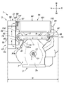
- FIG. 1 is a side view showing a V-type engine according to one embodiment of the present invention
- FIG. 1 is a bottom view showing a V-type engine according to one embodiment of the present invention
- FIG. 1 is a cross-sectional view showing a muffler according to one embodiment of the present invention
- V-type engine 1 (hereinafter abbreviated as "engine 1") according to an embodiment of the present invention will be described below with reference to FIGS. 1 to 3.
- FIG. hereinafter, for convenience of explanation, the left side of the drawing in FIG. 1 is defined as the front side (front side) of the engine 1 .
- fixed by a bolt it means a case where it is fixed by a normal bolt having a threaded portion only on one side, and a case where it is fixed by a normal bolt having a threaded portion on both sides. including both cases where it is fixed by a stud bolt with
- engine 1 is a general-purpose engine used as a power source for work implement P.
- the working machine P is a riding lawn mower.
- the engine 1 is configured by an OHV air-cooled two-cylinder engine.
- the engine 1 may be an engine of a type other than the OHV type (for example, an OHC type engine), or an engine of a type other than an air-cooled type (for example, a water-cooled engine). It may be an engine with three or more cylinders.
- the engine 1 has an engine body 3 , an air cleaner 4 arranged above the engine body 3 , and an exhaust device 5 arranged behind and below the engine body 3 .
- the constituent elements of the engine 1 will be described in order below.
- the engine body 3 includes a crankcase 7, a first cylinder bank 8 extending rearward right from the crankcase 7, a second cylinder bank 9 extending rearward left from the crankcase 7, contains.
- an engine mount 14 is arranged below the crankcase 7 .
- the crankcase 7 is attached to the main body of the working machine P via the engine mount 14 .
- a crankshaft 11 is rotatably supported in the central portion of the crankcase 7. As shown in FIG. The crankshaft 11 is rotatably provided around a rotation axis X extending in the vertical direction. That is, the engine 1 is a vertical type engine in which the rotation axis X of the crankshaft 11 extends vertically. In another embodiment, the engine 1 may be a horizontal type engine in which the rotation axis X of the crankshaft 11 extends horizontally.
- the work machine P is a cutting machine such as a concrete cutter, a floor processing machine such as a floor leveling machine, a high-pressure washer, a generator, or the like.
- a PTO shaft 12 (power take-off shaft: an example of an output portion) is provided at the lower end of the crankshaft 11 .
- the PTO shaft 12 is connected to a working portion of the working machine P (for example, a blade of a riding lawn mower), and is configured to rotate according to the rotation of the PTO shaft 12. .
- the PTO shaft 12 protrudes downward from the lower surface 7a of the crankcase 7 and extends vertically.
- the first and second cylinder banks 8 and 9 are arranged in the left-right direction (the width direction of the engine body 3).
- the first and second cylinder banks 8 and 9 are provided obliquely behind the crankcase 7, respectively.
- Pistons (not shown) are housed in front portions (cylinders) of the first and second cylinder banks 8 and 9 so as to be able to reciprocate.
- the piston is connected to the crankshaft 11 via a connecting rod (not shown).
- the rear portions (cylinder heads) of the first and second cylinder banks 8 and 9 define combustion chambers (not shown) together with the pistons.
- An intake port (not shown) that communicates with the combustion chamber is opened in the laterally inner surface of the rear portion of each of the first and second cylinder banks 8 and 9 .
- An exhaust port 19 communicating with the combustion chamber is opened in the lower surface of the rear portion of the first and second cylinder banks 8 and 9 .
- air cleaner 4 has a cylindrical shape (canister shape) extending in the left-right direction.
- the air cleaner 4 is positioned above the first and second cylinder banks 8 and 9 .
- the air cleaner 4 is connected to the intake ports (not shown) of the first and second cylinder banks 8 and 9 via intake pipes (not shown), and the air cleaned by the air cleaner 4 passes through the intake ports. into a combustion chamber (not shown).
- the exhaust device 5 is a device for discharging exhaust gas discharged from the engine body 3 to the outside of the engine 1 .
- it means upstream or downstream in the exhaust direction (that is, the direction in which the exhaust gas flows in the exhaust device 5).
- a dashed-dotted line arrow appropriately attached to each figure indicates the exhaust direction.
- the exhaust system 5 includes an exhaust collecting pipe 31, a catalyst 32, and a muffler 33.
- the constituent elements of the exhaust device 5 will be described in order below.
- the exhaust collecting pipe 31 of the exhaust device 5 is accommodated within the width W of the engine body 3 when viewed in the vertical direction (the axial direction of the crankshaft 11).
- the exhaust collecting pipe 31 includes a first exhaust pipe 41 , a second exhaust pipe 42 and a junction pipe 43 .
- the first exhaust pipe 41 of the exhaust collecting pipe 31 extends in the left-right direction.
- a first fixed flange 46 is provided on the outer periphery of the right end (upstream end) of the first exhaust pipe 41 .
- the first fixed flange 46 is fixed around the exhaust port 19 of the first cylinder bank 8 by a pair of bolts (not shown). Thereby, the right end portion of the first exhaust pipe 41 is connected to the exhaust port 19 of the first cylinder bank 8 .
- the second exhaust pipe 42 of the exhaust collecting pipe 31 extends in the left-right direction.
- a second fixed flange 48 is provided on the outer periphery of the left end (upstream end) of the second exhaust pipe 42 .
- the second fixed flange 48 is fixed around the exhaust port 19 of the second cylinder bank 9 by a pair of bolts (not shown).
- the left end of the second exhaust pipe 42 is connected to the exhaust port 19 of the second cylinder bank 9 .
- the right end (downstream end) of the second exhaust pipe 42 merges with the left end (downstream end) of the first exhaust pipe 41 at the junction M located below the first cylinder bank 8 . ing.
- the confluence pipe 43 of the exhaust collecting pipe 31 includes an introduction pipe portion 51 and an accommodation pipe portion 52 .
- the introduction pipe portion 51 of the confluence pipe 43 is provided integrally with the first and second exhaust pipes 41 and 42 .
- the introduction pipe portion 51 is composed of an upstream portion 51a and a downstream portion 51b arranged on the right front side (downstream side) of the upstream portion 51a.
- the upstream portion 51a extends linearly from the rear left side toward the front right side.
- a left rear end (upstream end) of the upstream portion 51 a is connected to a confluence portion M of the first and second exhaust pipes 41 and 42 below the first cylinder bank 8 .
- the downstream portion 51b is bent rightward from the right front end (downstream end) of the upstream portion 51a.
- the housing pipe portion 52 of the merging pipe 43 extends from the front end side (base end side) of the first cylinder bank 8 to the rear end side (tip side) of the first cylinder bank 8 in the front-rear direction. (the height direction of the engine body 3).
- the “height direction of the engine body 3" is, for example, the width direction of the engine body 3 (the direction in which the first and second cylinder banks 8 and 9 are arranged) and the direction perpendicular to the axial direction of the crankshaft 11. , which does not necessarily match the vertical direction in the actual space.
- the “height direction of the engine body 3 ” is, for example, a direction perpendicular to the straight line Q connecting the exhaust ports 19 of the first and second cylinder banks 8 and 9 .
- the outer peripheral surface of the housing pipe portion 52 may be fixed to the crankcase 7 and/or the first cylinder bank 8, or may be fixed to the main body of the working machine P.
- the housing pipe portion 52 includes an upstream portion 54 , a main body portion 55 arranged on the rear side of the upstream portion 54 , a downstream portion 56 arranged on the rear side of the main body portion 55 , and a left side of the downstream portion 56 (engine main body 3 ). and a connecting portion 57 projecting inward in the width direction of the .
- the upstream portion 54 and the main body portion 55, the main body portion 55 and the downstream portion 56, and the downstream portion 56 and the connection portion 57 are fixed by welding, respectively.
- the upstream portion 54 is connected to the right end (downstream end) of the downstream portion 51 b of the introduction pipe portion 51 on the front end side (base end side) of the first cylinder bank 8 .
- connection flange 60 is provided at the left end (downstream end) of the connection portion 57 .
- the connecting portion 57 may protrude from the downstream portion 56 in a direction other than the left side (for example, downward).
- the direction in which the connection portion 57 protrudes from the downstream portion 56 can be freely set according to the arrangement of the muffler 33 and the like.
- the catalyst 32 of the exhaust system 5 is composed of, for example, a three-way catalyst.
- the catalyst 32 purifies the exhaust gas by chemically converting harmful components of the exhaust gas discharged from the engine body 3 through the exhaust collecting pipe 31 into harmless components.
- the catalyst 32 has a columnar shape elongated in the front-rear direction. That is, in this embodiment, the longitudinal direction of the catalyst 32 is the front-rear direction.
- the catalyst 32 is housed in the housing pipe portion 52 (more specifically, the body portion 55 of the housing pipe portion 52) of the junction pipe 43 of the exhaust collecting pipe 31. As shown in FIG.
- the catalyst 32 is arranged at the boundary between the lower surface and the right surface (side surface) of the first cylinder bank 8 and positioned above the lower surface 7 a of the crankcase 7 .
- the catalyst 32 is arranged on the opposite side of the air cleaner 4 with the first and second cylinder banks 8 and 9 interposed therebetween when viewed in the left-right direction.
- the catalyst 32 extends in the longitudinal direction from the front end side (base end side) of the first cylinder bank 8 to the rear end side (tip side) of the first cylinder bank 8 .
- the catalyst 32 is positioned on the right side (outside in the width direction of the engine body 3) of the exhaust port 19 of the first cylinder bank 8 when viewed in the vertical direction.
- the catalyst 32 is accommodated within the width W of the engine body 3 when viewed in the vertical direction.
- muffler 33 of exhaust device 5 is arranged downstream of exhaust collecting pipe 31 .
- the muffler 33 is not welded to the exhaust collecting pipe 31, but is separably connected to the accommodating pipe portion 52 of the junction pipe 43 of the exhaust collecting pipe 31 on the rear end side (front end side) of the first cylinder bank 8.
- the muffler 33 has a muffler body 94, a plurality of partition walls 95, 96, an inflow pipe 97, a communication pipe 98, and a discharge pipe 99.
- the muffler main body 94 is arranged adjacent to the accommodation pipe portion 52 of the confluence pipe 43 on the left side of the accommodation pipe portion 52 of the confluence pipe 43 .
- the muffler main body 94 protrudes below the lower surface 7a of the crankcase 7. As shown in FIG.
- the muffler body 94 is arranged perpendicular to the catalyst 32 and extends in the left-right direction from the rear end side (front end side) of the first cylinder bank 8 to the rear end side (front end side) of the second cylinder bank 9 . Left and right side portions of the muffler body 94 overlap rear portions of the first and second cylinder banks 8 and 9 when viewed in the vertical direction.
- the muffler main body 94 is accommodated within the width W of the engine main body 3 when viewed in the vertical direction.
- the muffler main body 94 has a cylindrical shape elongated in the left-right direction. That is, in this embodiment, the longitudinal direction of the muffler main body 94 is the left-right direction. In other embodiments, the muffler main body 94 may have a shape other than a cylindrical shape (for example, a square tube shape).
- the muffler main body 94 includes a cylindrical portion 101 extending in the left-right direction and a pair of lid portions 102 covering openings at both ends of the cylindrical portion 101. As shown in FIG.
- the outer peripheral surface of the cylindrical portion 101 may be fixed to the crankcase 7 and/or the first and second cylinder banks 8 and 9, or may be fixed to the main body of the working machine P.
- multiple muffler chambers 111 to 113 are formed inside the muffler body 94 .
- the plurality of muffler chambers 111 to 113 are a first muffler chamber 111 formed at the right end of the muffler body 94, a second muffler chamber 112 formed at the left end of the muffler body 94, the first muffler chamber 111 and the second muffler chamber 111. and a third silencer chamber 113 formed between the two silencer chambers 112 .
- the volumes of the plurality of sound deadening chambers 111 to 113 decrease in order of the volume of the first sound deadening chamber 111, the volume of the second deadening chamber 112, and the volume of the third deadening chamber 113.
- An exhaust gas inlet 109 is provided at the right end of the first silencer chamber 111 .
- the inlet 109 is configured by a hole provided in the right lid portion 102 .
- the plurality of partition walls 95 and 96 includes a first partition wall 95 that partitions the first and third noise reduction chambers 111 and 113 in the horizontal direction, and a second partition wall 96 that partitions the second and third noise reduction chambers 112 and 113 in the horizontal direction. and includes A large number of small holes 115 are provided in the second partition wall 96 over the entire area, and the second sound deadening chamber 112 and the third sound deadening chamber 113 communicate with each other through the large number of small holes 115 .
- the inflow pipe 97 is arranged on the right side of the muffler body 94 (outside in the width direction of the engine body 3).
- the inflow pipe 97 extends in the left-right direction.
- a connection flange 117 is provided at the right end (upstream end) of the inflow pipe 97 .
- the connection flange 117 is fixed to the connection flange 60 of the housing pipe portion 52 of the junction pipe 43 with a pair of bolts (not shown).
- the left end (downstream end) of the inflow pipe 97 is connected to the inflow port 109 of the first silencer chamber 111 of the muffler body 94 .
- communication pipe 98 extends in the left-right direction.
- the communicating pipe 98 is supported by the first and second partition walls 95 and 96 by passing through the first and second partition walls 95 and 96 .
- a communication port 121 that communicates with the first silencer chamber 111 is provided at the right end (upstream end) of the communication pipe 98 .
- a cap 122 is fixed to the left end (downstream end) of the communicating pipe 98 by welding. Thereby, the left end of the communicating pipe 98 is covered with the cap 122 .
- a large number of communication holes 123 communicating with the second silencer chamber 112 are provided in the outer peripheral portion of the communication pipe 98 .
- the discharge pipe 99 extends in the left-right direction.
- the exhaust pipe 99 passes through the pair of lid portions 102 of the muffler body 94 and the first and second partition walls 95 and 96, thereby connecting the pair of lid portions 102 and the first and second partition walls 95 and 96 of the muffler body 94.
- a large number of outer peripheral holes 127 communicating with the third noise reduction chamber 113 are provided on the outer peripheral portion of the discharge pipe 99 .
- Both left and right ends of the discharge pipe 99 protrude to both sides of the muffler main body 94 in the left and right direction.
- a pair of openings 125 are provided at both left and right ends of the discharge pipe 99 .
- a lid member 126 is fixed by welding to an opening 125 formed at the right end of the discharge pipe 99 .
- the opening 125 formed at the right end of the discharge pipe 99 is closed by the lid member 126 .
- An opening 125 formed at the left end of the exhaust pipe 99 is not closed by a lid member 126 and communicates with the external space S on the left side of the muffler body 94 .
- the third silencer chamber 113 and the external space S on the left side of the muffler main body 94 communicate with each other through the exhaust pipe 99 .
- the opening 125 formed at the left end of the discharge pipe 99 is closed by the lid member 126 and the opening 125 formed at the right end of the discharge pipe 99 is opened.
- the third muffler chamber 113 and the outer space on the right side of the muffler main body 94 may communicate with each other through the exhaust pipe 99 .
- exhaust gas is discharged from exhaust ports 19 of first and second cylinder banks 8 and 9 when engine 1 is driven. After passing through the first and second exhaust pipes 41 and 42, the exhaust gas discharged from the exhaust port 19 sequentially passes through the introduction pipe portion 51 and the accommodation pipe portion 52 of the junction pipe 43, and then flows through the accommodation pipe of the junction pipe 43. It is discharged from the part 52 . As the exhaust gas passes through the accommodation pipe portion 52 of the junction pipe 43 in this way, the exhaust gas is purified by the catalyst 32 accommodated in the accommodation pipe portion 52 of the junction pipe 43 .
- the exhaust gas discharged from the accommodation pipe portion 52 of the confluence pipe 43 flows into the inflow pipe 97 of the muffler 33 .
- the exhaust gas flows through the inflow port 109 into the first silencer chamber 111 of the muffler 33 .
- the exhaust gas that has flowed into the first noise reduction chamber 111 passes through the first noise reduction chamber 111 and then flows into the communication pipe 98 of the muffler 33 through the communication port 121 .
- the exhaust gas that has flowed into the communication pipe 98 flows through the communication pipe 98 and then into the second silencer chamber 112 of the muffler 33 through a large number of communication holes 123 .
- the exhaust gas flows into the third silencer chamber 113 of the muffler 33 through the small holes 115 of the second partition 96 .
- the exhaust gas that has flowed into the third silencer chamber 113 passes through the third silencer chamber 113 and then flows into the exhaust pipe 99 of the muffler 33 through the many outer perimeter holes 127 .
- the exhaust gas that has flowed into the exhaust pipe 99 passes through the exhaust pipe 99 and is then discharged to the external space S on the left side of the muffler body 94 through an opening 125 formed at the left end of the exhaust pipe 99 . Exhaust noise is reduced by passing the exhaust gas through the muffler 33 in this way.
- the muffler 33 is separably connected to the accommodation pipe portion 52 of the junction pipe 43 of the exhaust collecting pipe 31 .
- the user can appropriately set the muffler 33 according to the configuration of the work machine P on which the engine 1 is mounted. Therefore, the degree of freedom in setting the muffler 33 can be improved.
- the catalyst 32 extends in the longitudinal direction from the front end side (base end side) of the first cylinder bank 8 to the rear end side (tip side) of the first cylinder bank 8 .
- the engine body 3 and the catalyst 32 can be arranged compactly, and the engine 1 can be made compact.
- the exhaust gas purification performance can be enhanced.
- the catalyst 32 is accommodated in the junction pipe 43 .
- the number of catalysts 32 can be reduced compared to the case where the catalysts 32 are housed in the first and second exhaust pipes 41 and 42, respectively. can be simplified.
- the confluence pipe 43 is composed of an introduction pipe portion 51 and an accommodation pipe portion 52 . Therefore, the length of the catalyst 32 can be sufficiently secured while simplifying the configuration of the junction pipe 43 as much as possible.
- the muffler 33 is connected to the housing pipe portion 52 of the junction pipe 43 on the rear end side (front end side) of the first cylinder bank 8 . Therefore, the muffler 33 can be arranged in both the left-right direction (the width direction of the engine body 3) and the front-rear direction (the height direction of the engine body 3) without making the muffler 33 protrude greatly with respect to the engine body 3. (See FIGS. 2 and 4). Therefore, the degree of freedom in setting the muffler 33 can be improved.
- the muffler main body 94 extends in the left-right direction from the rear end side (front end side) of the first cylinder bank 8 to the rear end side (front end side) of the second cylinder bank 9 (see FIG. 2). ).
- the length of the muffler body 94 can be sufficiently secured without protruding greatly from the engine body 3 . Therefore, it is possible to increase the volume of the muffler main body 94 and improve the silencing performance.
- the muffler main body 94 extends from the rear end side (front end side) of the first cylinder bank 8 to the front end side (base end side) of the first cylinder bank 8 in the longitudinal direction (the height of the engine main body 3). direction) (see FIG. 4).
- the air cleaner 4 has a canister shape and is arranged on the opposite side of the catalyst 32 with the first and second cylinder banks 8 and 9 interposed therebetween when viewed in the left-right direction.
- the air cleaner 4 has a flat plate shape and may be arranged between the first and second cylinder banks 8 and 9 (see FIG. 4). By effectively using the space between the first and second cylinder banks 8 and 9 to arrange the air cleaner 4, the engine 1 can be made more compact.
- the catalyst 32 is positioned above the lower surface 7a of the crankcase 7.
- the canister-shaped air cleaner 4 can be arranged on the first and second cylinder banks without causing the catalyst 32 to protrude below the lower surface 7a of the crankcase 7 . 8, 9, or the flat plate-shaped air cleaner 4 can be arranged between the first and second cylinder banks 8, 9. Therefore, the compatibility of the air cleaner 4 can be improved, and the degree of freedom in setting the air cleaner 4 can be improved.
- the catalyst 32 is positioned on the right side (outside in the width direction of the engine body 3) of the exhaust port 19 of the first cylinder bank 8.
- the present invention can be widely modified without being limited to the above embodiments. That is, the positions, orientations, etc. of the components of the exhaust system 5 can be freely changed according to the requirements of the work machine P (for example, a generator, a welding machine, a lawn mower, a tiller, etc.) on which the engine 1 is mounted. be. Accordingly, the position and exhaust direction of the muffler 33 are not limited to the above embodiment, and can be freely set within the scope of the present invention. For example, when the work machine P on which the engine 1 is mounted is used in an orchard, it is preferable to set the position and exhaust direction of the muffler 33 so that the exhaust gas discharged from the muffler 33 does not hit fruit trees.
- the work machine P for example, a generator, a welding machine, a lawn mower, a tiller, etc.
Landscapes
- Engineering & Computer Science (AREA)
- Chemical & Material Sciences (AREA)
- Chemical Kinetics & Catalysis (AREA)
- Combustion & Propulsion (AREA)
- Mechanical Engineering (AREA)
- General Engineering & Computer Science (AREA)
- Health & Medical Sciences (AREA)
- Toxicology (AREA)
- Exhaust Silencers (AREA)
Abstract
Le problème décrit par la présente invention est d'augmenter le degré de liberté dans la mise en place d'un silencieux et d'assurer une longueur suffisante d'un catalyseur tout en obtenant une réduction de la taille d'un moteur de type V. La solution selon l'invention porte sur un moteur de type V 1 qui comprend : un corps 3 de moteur ayant un carter 7 de vilebrequin pour supporter un vilebrequin 11 de manière rotative et des première et seconde rangées de cylindres 8, 9 s'étendant à partir du carter 7 de vilebrequin ; un tuyau de collecte d'échappement 31 relié aux première et seconde rangées de cylindres 8, 9 ; un catalyseur 32 logé dans le tuyau de collecte d'échappement 31 ; et un silencieux 33 relié au tuyau de collecte d'échappement 31 d'une manière séparable. Le catalyseur 32 s'étend du côté extrémité de base de la première rangée de cylindres 8 au côté extrémité avant de la première rangée de cylindres 8, dans le sens de la hauteur du corps 3 de moteur.
Priority Applications (2)
| Application Number | Priority Date | Filing Date | Title |
|---|---|---|---|
| US18/549,527 US12134979B2 (en) | 2021-03-10 | 2021-03-10 | V-type engine including catalyst extending in height direction of engine body and work machine including same |
| PCT/JP2021/009504 WO2022190251A1 (fr) | 2021-03-10 | 2021-03-10 | Moteur de type v et engin de chantier |
Applications Claiming Priority (1)
| Application Number | Priority Date | Filing Date | Title |
|---|---|---|---|
| PCT/JP2021/009504 WO2022190251A1 (fr) | 2021-03-10 | 2021-03-10 | Moteur de type v et engin de chantier |
Publications (1)
| Publication Number | Publication Date |
|---|---|
| WO2022190251A1 true WO2022190251A1 (fr) | 2022-09-15 |
Family
ID=83226428
Family Applications (1)
| Application Number | Title | Priority Date | Filing Date |
|---|---|---|---|
| PCT/JP2021/009504 Ceased WO2022190251A1 (fr) | 2021-03-10 | 2021-03-10 | Moteur de type v et engin de chantier |
Country Status (2)
| Country | Link |
|---|---|
| US (1) | US12134979B2 (fr) |
| WO (1) | WO2022190251A1 (fr) |
Families Citing this family (1)
| Publication number | Priority date | Publication date | Assignee | Title |
|---|---|---|---|---|
| US12510012B1 (en) * | 2024-06-26 | 2025-12-30 | Kawasaki Motors, Ltd. | Engine and exhaust structure |
Citations (4)
| Publication number | Priority date | Publication date | Assignee | Title |
|---|---|---|---|---|
| JPH0510772U (ja) * | 1991-07-23 | 1993-02-12 | 本田技研工業株式会社 | V型エンジン |
| JPH05246389A (ja) * | 1992-03-06 | 1993-09-24 | Yamaha Motor Co Ltd | 船外機の排気ガス浄化装置 |
| JP2006226187A (ja) * | 2005-02-17 | 2006-08-31 | Toyota Motor Corp | 横置きv型エンジンの排気浄化装置 |
| JP2008247359A (ja) * | 2007-03-30 | 2008-10-16 | Honda Motor Co Ltd | 船外機における排気装置 |
Family Cites Families (6)
| Publication number | Priority date | Publication date | Assignee | Title |
|---|---|---|---|---|
| US3884658A (en) * | 1972-04-18 | 1975-05-20 | Pall Corp | Air cleaner for supercharged engines |
| US4482365A (en) * | 1982-03-01 | 1984-11-13 | Pall Corporation | Vortex air cleaner and self-cleaning barrier filter assembly for supercharged engines |
| US5014816A (en) * | 1989-11-09 | 1991-05-14 | E. I. Du Pont De Nemours And Company | Silencer for gas induction and exhaust systems |
| JP2003184547A (ja) * | 2001-12-18 | 2003-07-03 | Yamaha Marine Co Ltd | 小型船舶 |
| DE102004016478A1 (de) * | 2004-03-31 | 2005-10-20 | Mann & Hummel Gmbh | Ansaugsystem einer Brennkraftmaschine |
| JP2006009648A (ja) * | 2004-06-24 | 2006-01-12 | Honda Motor Co Ltd | 自動二輪車の排気浄化装置 |
-
2021
- 2021-03-10 WO PCT/JP2021/009504 patent/WO2022190251A1/fr not_active Ceased
- 2021-03-10 US US18/549,527 patent/US12134979B2/en active Active
Patent Citations (4)
| Publication number | Priority date | Publication date | Assignee | Title |
|---|---|---|---|---|
| JPH0510772U (ja) * | 1991-07-23 | 1993-02-12 | 本田技研工業株式会社 | V型エンジン |
| JPH05246389A (ja) * | 1992-03-06 | 1993-09-24 | Yamaha Motor Co Ltd | 船外機の排気ガス浄化装置 |
| JP2006226187A (ja) * | 2005-02-17 | 2006-08-31 | Toyota Motor Corp | 横置きv型エンジンの排気浄化装置 |
| JP2008247359A (ja) * | 2007-03-30 | 2008-10-16 | Honda Motor Co Ltd | 船外機における排気装置 |
Also Published As
| Publication number | Publication date |
|---|---|
| US12134979B2 (en) | 2024-11-05 |
| US20240159177A1 (en) | 2024-05-16 |
Similar Documents
| Publication | Publication Date | Title |
|---|---|---|
| JP3930961B2 (ja) | 内燃エンジンのマフラー | |
| JP5417610B2 (ja) | 高性能排気システム | |
| JP3932439B2 (ja) | 小型自動二輪車の排気系への2次空気供給装置 | |
| JP2009154767A (ja) | 自動二輪車の触媒配置構造 | |
| US12134977B2 (en) | V-type engine | |
| JP2020133489A (ja) | 自動二輪車 | |
| WO2022190251A1 (fr) | Moteur de type v et engin de chantier | |
| JP2022130576A (ja) | エンジン | |
| US11781461B2 (en) | Exhaust device of engine and work machine | |
| WO2022190252A1 (fr) | Moteur en v et machine de travail | |
| US12110815B2 (en) | V-type engine and work machine | |
| WO2022180745A1 (fr) | Moteur à usage général et machine de travail | |
| WO2022190250A1 (fr) | Moteur en forme de v et machine de travail | |
| JP7211108B2 (ja) | 車両用内燃機関の補機支持構造 | |
| US20220268186A1 (en) | Muffler for engine, air-cooled engine, and work machine | |
| WO2022180743A1 (fr) | Silencieux de moteur, moteur en v et engin de chantier | |
| WO2022180744A1 (fr) | Dispositif d'échappement pour moteur, engin de chantier, et procédé de fabrication de tuyau de catalyseur | |
| JP7196635B2 (ja) | 車両用内燃機関 | |
| CN215333048U (zh) | 一种用于园林绿化的除草机消音器 | |
| CN111542685B (zh) | 具有界定出多个腔室的挡板的消音器 | |
| JP7259354B2 (ja) | 車両用内燃機関の補機支持構造 | |
| RU2362023C1 (ru) | Глушитель | |
| JP7176423B2 (ja) | 車両用内燃機関 | |
| JPH09273416A (ja) | 2サイクルエンジンのマフラー | |
| RU2002113423A (ru) | Глушитель выхлопа для двигателей внутреннего сгорания |
Legal Events
| Date | Code | Title | Description |
|---|---|---|---|
| 121 | Ep: the epo has been informed by wipo that ep was designated in this application |
Ref document number: 21930108 Country of ref document: EP Kind code of ref document: A1 |
|
| WWE | Wipo information: entry into national phase |
Ref document number: 18549527 Country of ref document: US |
|
| NENP | Non-entry into the national phase |
Ref country code: DE |
|
| 122 | Ep: pct application non-entry in european phase |
Ref document number: 21930108 Country of ref document: EP Kind code of ref document: A1 |
|
| NENP | Non-entry into the national phase |
Ref country code: JP |