WO2022190833A1 - Dispositif de commande pour machine de travail, et machine de travail - Google Patents
Dispositif de commande pour machine de travail, et machine de travail Download PDFInfo
- Publication number
- WO2022190833A1 WO2022190833A1 PCT/JP2022/006837 JP2022006837W WO2022190833A1 WO 2022190833 A1 WO2022190833 A1 WO 2022190833A1 JP 2022006837 W JP2022006837 W JP 2022006837W WO 2022190833 A1 WO2022190833 A1 WO 2022190833A1
- Authority
- WO
- WIPO (PCT)
- Prior art keywords
- user
- operating device
- operation surface
- work machine
- machine according
- Prior art date
- Legal status (The legal status is an assumption and is not a legal conclusion. Google has not performed a legal analysis and makes no representation as to the accuracy of the status listed.)
- Ceased
Links
Images


Classifications
-
- A—HUMAN NECESSITIES
- A01—AGRICULTURE; FORESTRY; ANIMAL HUSBANDRY; HUNTING; TRAPPING; FISHING
- A01B—SOIL WORKING IN AGRICULTURE OR FORESTRY; PARTS, DETAILS, OR ACCESSORIES OF AGRICULTURAL MACHINES OR IMPLEMENTS, IN GENERAL
- A01B69/00—Steering of agricultural machines or implements; Guiding agricultural machines or implements on a desired track
-
- A—HUMAN NECESSITIES
- A01—AGRICULTURE; FORESTRY; ANIMAL HUSBANDRY; HUNTING; TRAPPING; FISHING
- A01D—HARVESTING; MOWING
- A01D41/00—Combines, i.e. harvesters or mowers combined with threshing devices
- A01D41/12—Details of combines
- A01D41/127—Control or measuring arrangements specially adapted for combines
-
- A—HUMAN NECESSITIES
- A01—AGRICULTURE; FORESTRY; ANIMAL HUSBANDRY; HUNTING; TRAPPING; FISHING
- A01D—HARVESTING; MOWING
- A01D67/00—Undercarriages or frames specially adapted for harvesters or mowers; Mechanisms for adjusting the frame; Platforms
-
- B—PERFORMING OPERATIONS; TRANSPORTING
- B60—VEHICLES IN GENERAL
- B60K—ARRANGEMENT OR MOUNTING OF PROPULSION UNITS OR OF TRANSMISSIONS IN VEHICLES; ARRANGEMENT OR MOUNTING OF PLURAL DIVERSE PRIME-MOVERS IN VEHICLES; AUXILIARY DRIVES FOR VEHICLES; INSTRUMENTATION OR DASHBOARDS FOR VEHICLES; ARRANGEMENTS IN CONNECTION WITH COOLING, AIR INTAKE, GAS EXHAUST OR FUEL SUPPLY OF PROPULSION UNITS IN VEHICLES
- B60K20/00—Arrangement or mounting of change-speed gearing control devices in vehicles
- B60K20/02—Arrangement or mounting of change-speed gearing control devices in vehicles of initiating means
-
- B—PERFORMING OPERATIONS; TRANSPORTING
- B60—VEHICLES IN GENERAL
- B60Y—INDEXING SCHEME RELATING TO ASPECTS CROSS-CUTTING VEHICLE TECHNOLOGY
- B60Y2200/00—Type of vehicle
- B60Y2200/20—Off-Road Vehicles
- B60Y2200/22—Agricultural vehicles
- B60Y2200/222—Harvesters
Definitions
- the present invention relates to an operating device for a working machine and a working machine.
- a work machine having an operating device such as a main shift lever in a cabin
- the main shift lever has a body (grip) that a user (operator) grips with the left hand. is manipulated.
- the main shift lever has various switches such as a reaping shift switch and an auxiliary shift switch on the operation surface (upper surface) of the body, and is arranged so that the operation surface is inclined toward the user in the driver's seat. It is A user operates various switches of the main shift lever mainly with the thumb of the left hand.
- the palm of the user may touch various switches, and the user may unintentionally perform various actions. It may lead to an erroneous operation in which the switch is operated.
- An object of the present invention is to provide an operation device for a work machine and a work machine that can easily prevent erroneous operation.
- An operation device for a work machine is an operation device that is mounted on the body of the work machine and receives an operation by a user, and includes a body and an operation target.
- the body includes an operating surface on a portion of its surface.
- the operation target is arranged on the operation surface.
- the operation device is configured to be able to receive a first operation including an operation on the operation target and a second operation involving movement of the body.
- the operation device further includes an erroneous operation prevention section protruding from the operation surface.
- a working machine includes an operating device for the working machine, and a body on which the operating device is mounted.
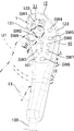
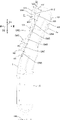
- FIG. 1 is a schematic perspective view showing an operating device for a work machine according to Embodiment 1.
- FIG. 2 is a schematic left side view of the work machine according to Embodiment 1.
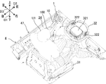
- FIG. 3 is a schematic perspective view and a partially enlarged view showing an operating section of the work machine according to Embodiment 1.
- FIG. 4 is a schematic perspective view showing a state in which a user is on the operating section of the work machine according to Embodiment 1.
- FIG. FIG. 5 is a schematic front view showing an operating section of the work machine according to Embodiment 1.
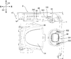
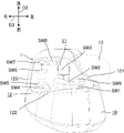
- FIG. FIG. 6 is a schematic plan view of the operating device for the work machine according to Embodiment 1, viewed from the operating surface side.
- FIG. 7 is a schematic right side view showing the operation device for the work machine according to Embodiment 1.
- FIG. 8 is a schematic top view showing the operating device for the work machine according to Embodiment 1.
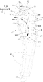
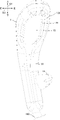
- FIG. 9 is a schematic plan view of the operating device for the work machine according to Embodiment 1 as seen from the back side.
- FIG. 10 is a schematic plan view of another operating device for the work machine according to Embodiment 1, viewed from the back side.
- the work machine 4 includes a body 40 including a travel device 41 and the like.
- An operating device 1 (see FIG. 1) for a working machine according to the present embodiment is mounted on the body 40 of such a working machine 4. As shown in FIG.
- the "working machine” referred to in the present disclosure means a machine that performs various kinds of work in a work area such as a field F1, and examples thereof include harvesting machines (including combine harvesters), tractors, rice transplanters, spreaders, sprayers, They are work vehicles such as seeders and transplanters. That is, work machine 4 includes a work vehicle.
- the work machine 4 is not limited to a "vehicle”, and may be, for example, a work projectile or a work vessel. Further, the work machine 4 is not limited to agricultural machines (agricultural machines), and may be construction machines (construction machines), for example. In this embodiment, unless otherwise specified, the case where the working machine 4 is a riding-type harvesting machine will be described as an example.
- a “harvesting machine” as used in the present disclosure is a machine that performs crop harvesting in the field F1, and includes, for example, a combine (combine harvester) that performs threshing and sorting in addition to harvesting.
- the combine as the work machine 4 is mainly used for grain harvesting, and harvests crops while moving (running) in the field F1.
- there are two types of combine harvesters a general-purpose combine harvester that feeds the entire harvested crop into a threshing machine (threshing device 43) and a self-threshing type combine harvester that feeds only the tips of the harvested crop into the threshing machine.
- a self-throwing combine harvester will be described as an example of the work machine 4 .
- the work machine 4 is operated by a person (operator) (including remote control). machine.
- the “field” referred to in the present disclosure is an area where the work machine 4 performs harvesting work, and is, for example, a rice field, a field, or an orchard in which crops (agricultural products) to be harvested such as rice, wheat, soybeans, or buckwheat are grown. and pastures, etc.
- crops agricultural products
- crops agricultural products
- pastures etc.
- a case where the harvest target by the working machine 4 is "wheat" and the field F1 is an outdoor field where wheat is grown will be described.
- the vertical direction in which the work machine 4 is usable is defined as the vertical direction D1.
- the front-rear direction D2 and the left-right direction D3 are defined with reference to the direction viewed from the person (operator) riding (the operating section 47 of) the work machine 4 .
- the directions used in the present embodiment are defined with reference to the machine body 40 of the work machine 4.
- the direction in which the fuselage 40 moves when the machine 4 moves backward is “rear”.
- the direction in which the front end of the machine body 40 moves when the work machine 4 turns to the right is “right”
- the direction in which the front end of the machine body 40 moves when the work machine 4 turns to the left is “left”.
- these directions are not meant to limit the directions in which the work machine 4 is used (directions during use).
- the working machine 4 includes a harvesting device 42 , a threshing device 43 , a sorting device 44 , a storage device 45 , a power device 46 , an operation section 47 , and the like on the body 40 .
- the working machine 4 further includes a control device, a communication terminal, a fuel tank, a battery, and the like on the body 40 .
- the work machine 4 further includes an operating device 1 for the working machine (hereinafter also simply referred to as "operating device"). That is, the machine body 40, which is the main body of the work machine 4, includes a traveling device 41, a harvesting device 42, a threshing device 43, and the like.
- the operating device 1 configures the working machine 4 as a harvesting machine together with the machine body 40 .
- the harvesting machine (work machine 4 ) includes the operating device 1 for the work machine and the machine body 40 .
- the travel device 41 includes a crawler section and can move the working machine 4 in the front-rear direction D2 and the left-right direction D3.
- the work machine 4 performs harvesting while moving in the farm field F1.
- the work machine 4 may move in the farm field F1 while turning from the outside to the inside to the left. becomes.
- the reaping device 42 reaps crops (in this embodiment, wheat as an example) in field F1.
- the harvesting device 42 is arranged in front of the machine body 40 (see FIG. 2) of the working machine 4 and coupled to the machine body 40 .
- the harvesting device 42 forms part of the components of the work machine 4 .
- the reaping device 42 includes a plurality (seven as an example) of weed dividing plates 421, a triggering device 422, and a reaping blade (cutter).
- the reaping device 42 is a reaping device for “six-row reaping” capable of reaping six grain stalks at the same time.
- a plurality of weed dividing plates 421 are arranged side by side in the left-right direction D3 at the lower end portion on the front side of the reaping device 42 .
- a plurality of dividing plates 421 are inserted between crops (grain stalks) to define the width to cut the crops. Furthermore, the dividing plate 421 has a function of guiding the crops divided by the dividing plate 421 to the raising device 422 .
- the raising device 422 has raising tines for rectifying the crops, and performs a "raising operation” such as picking up lodged crops and converging the tips (tips) of the crops to a certain width.
- the hoisting device 422 rotates the chain provided with the hoisting tines to drive the hoisting tines and perform the hoisting work.
- the crops guided by the dividing plate 421 are raised by the raising device 422, and cut near the root portion by the cutting blade to be mowed. As a result, the crop is cut in the middle of the stalk, and the stalk including at least the tip is harvested by the working machine 4 .
- the stalks of crops harvested by the harvesting device 42 are conveyed to the threshing device 43 .
- the threshing device 43 threshes the crops (grain stalks) harvested by the harvesting device 42 .
- the threshing process separates the threshing containing grains from the culms.
- the threshing falls from the threshing device 43 to the sorting device 44 below.
- the sorting device 44 executes a sorting process of sorting out grains from the threshing that falls from the threshing device 43 .
- the sorting device 44 sorts out grains from the threshed grains by, for example, sieving the threshed grains while applying air to the threshed grains obliquely from below.
- the storage device 45 has a grain tank 451, a discharge auger 452, and the like.
- the grain tank 451 stores grains transported from the sorting device 44 by the transport conveyor. That is, the grains sorted by the sorting device 44 are transported to the grain tank 451 by the transport conveyor and stored in the grain tank 451 .
- the discharge auger 452 discharges grains in the grain tank 451 to an arbitrary location around the working machine 4 .
- the power unit 46 is a drive source for the traveling device 41, the harvesting device 42, the threshing device 43, the sorting device 44, the storage device 45, and the like.
- the power unit 46 has, for example, an engine such as a diesel engine as a power source.
- the power unit 46 may have a motor (electric motor) as a power source, or may have a hybrid power source including an engine and a motor.
- the driving unit 47 includes a driver's seat 31 (see FIG. 3) on which the user U1 (see FIG. 4) sits, a steering wheel 32 (see FIG. 3) operated by the user U1, various operation levers and various operation switches. etc. is provided.
- the operating device 1 according to the present embodiment is included in an operating system provided in the operating section 47 .
- the operating device 1 is provided in the operating section 47 and is operated by a user (operator) U1 who is on the operating section 47 .
- the driving unit 47 is of a cabin type having a cabin 471, and the user U1 boards in a cabin space inside the cabin 471. As shown in FIG.
- the operating device 1 is also arranged in the cabin space inside the cabin 471 .
- the operating unit 47 will be described in detail in the column "[2] Configuration of the operating unit", and the operating device 1 will be described in detail in the column “[3] Configuration of the operating device”.
- the control device controls the traveling device 41, the harvesting device 42, the threshing device 43, the sorting device 44, the storage device 45, the power device 46, etc. according to the operation received by the operating system including the operating device 1.
- the operation received by the operation device 1 includes an operation for moving (forward or backward) the aircraft 40, and the control device receives the operation for moving the operation device 1 forward.
- the travel device 41 is controlled to move the body 40 forward (forward).
- the control device controls the travel device 41 to move the machine body 40 backward (to move backward).
- the communication terminal communicates with a server or the like external to the work machine 4.
- the communication terminal is configured to indicate the operation status of the work machine 4, the current position of the work machine 4, the yield of the crop, the taste of the crop (including protein content or water content, etc.), the working time, or the working efficiency. etc., to a server or the like as appropriate.
- the communication terminal is configured to detect the current position of the work machine 4 using a satellite positioning system such as GNSS (Global Navigation Satellite System). Further, the communication terminal may receive control information related to driving assistance or automatic driving of the work machine 4 from a server or the like.
- GNSS Global Navigation Satellite System
- information (yield data) about the harvested amount can be obtained by detecting the amount of harvested grains with a sensor (grain sensor) provided in the work machine 4 .
- a sensor grain sensor
- this type of sensor includes an impact detection unit such as a strain gauge or a piezoelectric element attached to the upper surface of the grain tank 451, and when the grain transported toward the grain tank 451 collides with the impact detection unit to detect the impact force of
- the method of obtaining the yield of the work machine 4 is not limited to this.
- the work machine 4 configured as described above can cut the crops grown in the field F1 and thresh them to take out the grains by performing the reaping work while traveling in the field F1.
- FIG. 3 to 5 show only the main parts arranged in the cabin space inside the cabin 471 (see FIG. 2) in the operation part 47, and the other parts are omitted as appropriate. Furthermore, in FIGS. 3 to 5, illustration of the cabin 471 surrounding the cabin space is also omitted.
- the driving section 47 is arranged in front of the grain tank 451 (see FIG. 2) on the right side of the machine body of the work machine 4 . Further, the operating section 47 is positioned behind the harvesting device 42 and above the power device 46 (see FIG. 2). With such an arrangement, the user U1 gets on and off the driving section 47 from the right side of the driving section 47 . Therefore, in the present embodiment, the entrance/exit through which the user U1 passes is arranged on the right side (right side) of the driving unit 47 in one of the left and right directions D3. That is, the user U ⁇ b>1 gets on and off the driving unit 47 through the entrance opening on the right side of the driving unit 47 .
- the cabin 471 has a cabin frame, a cabin roof, a door (cabin door), and the like.
- the cabin frame is a structure as a skeleton of the cabin 471 and is formed so as to surround the cabin space.
- the cabin roof is arranged above the cabin frame and supported by the cabin frame.
- the door is provided at the entrance and is rotatable between a "closed position” covering the entrance and an "open position” opening the entrance so that the user U1 can pass through.
- the door body is supported by the cabin frame so as to be rotatable around the rotation axis.
- the door is arranged on the right side of the operation section 47, so the door is also arranged on the right side of the operation section 47.
- the door body may be of a "front-opening type" in which the front side in the front-rear direction D2 opens, or a "rear-opening type” in which the rear side opens.
- the cabin 471 further has various panel materials including a glass panel as a windshield. These various panel members are appropriately attached to both sides of the cabin frame in the front-rear direction D2 and both sides in the left-right direction D3, and surround the cabin space from all sides together with the door. Furthermore, the cabin roof (or cabin frame) is appropriately equipped with external components such as mirrors.
- the cabin type operation unit 47 including the cabin 471 as in the present embodiment at least the cabin frame functions as a skeleton of the cabin 471 and has sufficient strength ( rigidity). Also, the cabin 471 may be removable from the body of the work machine 4 .
- the operation unit 47 includes a display (monitor), gauges, etc., in addition to various operation systems including the driver's seat 31 and the steering wheel 32 .
- the driver's seat 31 , various operating systems, displays, instruments, and the like are all arranged in a cabin space within the cabin 471 .
- the driver's seat 31 is arranged facing forward in a substantially central portion of the cabin space in plan view (top view).
- the driver's seat 31 is configured such that the position (height) of the seat surface in the up-down direction D1 and the position in the front-rear direction D2 can be adjusted.
- the driver's seat 31 has foldable armrests on both sides in the left-right direction D3.
- the steering wheel 32 is arranged on a steering column 33 provided in front of the driver's seat 31 . Therefore, when the user U1 is seated on the driver's seat 31, the steering wheel 32 is positioned in front of the user U1 as shown in FIG.
- the handle 32 is rotatable with respect to the steering column 33 , and the control device turns the working machine 4 according to the rotation angle of the handle 32 .
- a display 321 for displaying the operating state of the work machine 4 is provided at the center of the handle 32 .
- the steering wheel 32 is provided with a steering switch 322 .
- a side column 34 is provided in the cabin space on the opposite side (left side) of the entrance/exit in the left-right direction D3 with respect to the driver's seat 31 .
- the operation device 1 as a main transmission lever, a work clutch lever 35, various switches, operation dials, and the like are arranged.
- the operating device 1 is arranged at a position near the front end of the side column 34 so as to be easily visible to the user U1 seated on the driver's seat 31. It is located behind the shift lever).
- the operation device 1 and the work clutch lever 35 both have a grip, and the user U1 grasps the grip and operates the operation device 1 or the work clutch lever 35 as a whole to move (including rotation and tilting).
- the operating device 1 has a shaft 100 and a body 10 supported by the tip (upper end) of the shaft 100, and the body 10 functions as a "grip". That is, the user U1 moves the entire operation device 1 including the shaft 100 by moving the body 10 in the front-rear direction D2 while gripping (gripping) the body 10, thereby operating the operation device 1. .
- a part of the surface of the body 10 constitutes an operation surface 101, on which an operation object 11 including a plurality of operators SW1, SW2, SW3, . . . is arranged.
- the operation target 11 will be described in detail in the section "[3] Configuration of operation device".
- the side column 34 is formed with a first slit 341 and a second slit 342 .
- the operating device 1 is configured such that the shaft 100 passes through the side column 34 through the first slit 341 in the vertical direction D1 and is movable along the first slit 341 .
- the work clutch lever 35 passes through the side column 34 in the vertical direction D ⁇ b>1 through the second slit 342 and is configured to be movable along the second slit 342 .
- the operating device 1 as the main gear lever is used to operate the traveling device 41 and the like, and as an example, moves (that is, switches) between a "forward position", a "reverse position", and a "neutral position”. , operated by user U1.
- the operation device 1 is movable in the front-rear direction D2, and the front end position of the movement range is the "forward position", the rear end position of the movement range is the “reverse position”, and the intermediate position of the movement range is the "neutral position”. position”.
- the control device stops the machine body 40 when the operating device 1 is in the "neutral position", and advances the machine body 40 when the operating device 1 moves from the "neutral position" to the "advance position" side (that is, forward).
- the control device adjusts the running speed steplessly according to the amount of operation of the operating device 1, that is, the amount of movement from the "neutral position". For example, the larger the amount of forward movement of the operating device 1 from the "neutral position", the faster the fuselage 40 moves forward.
- the work clutch lever 35 is used to operate the reaping device 42, the threshing device 43, etc., and as an example, is moved (that is, switched) between a "reaping position", a "threshing position", and an "OFF position". It is operated by user U1.
- the control device operates both the harvesting device 42 and the threshing device 43 when the work clutch lever 35 is in the "reaping position”, stops the harvesting device 42 and operates the threshing device 43 when it is in the "threshing position", If in the "OFF position", both the harvester 42 and the threshing device 43 are stopped.
- an auxiliary shift lever 36 is arranged between the driver's seat 31 and the side column 34, that is, on the left side of the driver's seat 31.
- the sub-transmission lever 36 is a lever-type operation tool used to switch the running speed of the machine body 40, and as an example, moves between a "raft position", a "working position” and a "neutral position". (that is, switch) is operated by the user U1.
- the control device sets the travel speed suitable for overpassing or loading and unloading of the work machine 4 onto and off the truck. 4. Set the traveling speed suitable for moving traveling.
- the operating device 1 as the main gear lever, the working clutch lever 35 and the auxiliary gear lever 36 are all located on one side of the driver's seat 31 in the left-right direction D3 (the left side in this embodiment). Therefore, the user U1 seated on the driver's seat 31 normally operates the operation device 1, the work clutch lever 35, and the sub-transmission lever 36 with the left hand.
- FIG. 1 and 6 to 9 the configuration of the operation device 1 of the working machine 4 according to the present embodiment will be described in more detail with reference to FIGS. 1 and 6 to 9.
- FIG. 1 and 6 to 9 only the operating device 1 is illustrated, and illustration of other configurations is omitted.
- the operating device 1 is a lever-type operating tool
- the posture (orientation, etc.) of the operating device 1 is appropriately changed by an operation (second operation) involving movement of the body 10 . Therefore, the posture of the operation device 1 can change as appropriate in the up-down direction D1, the front-rear direction D2, and the left-right direction D3 defined with the machine body 40 of the work machine 4 as a reference.
- FIGS. 6 to 9 it is assumed that the operating device 1 is in a state in which the longitudinal direction of the body 10 coincides with the vertical direction D1 and the operation surface 101 of the body 10 faces rearward. and explain.
- the operation device 1 is an operation device that is mounted on the body 40 of the work machine 4 and receives operations by the user U1.
- the operation device 1 includes a body 10 and an operation target 11, as shown in FIG.
- the body 10 includes an operation surface 101 on part of its surface.
- the operation target 11 is arranged on the operation surface 101 .
- the operation device 1 is configured to be able to receive a first operation including an operation on the operation target 11 and a second operation involving movement of the body 10 .
- the operation device 1 can accept at least two types of operations, a "first operation” and a "second operation", from the user U1. Therefore, the user U1 can perform at least two types of operations, a “first operation” and a “second operation”, using one operation device 1 .
- the operation surface 101 is provided on the surface of the body 10 on the side of the user U1 seated in the driver's seat 31, that is, on the rearward facing portion (rear surface).
- the operation surface 101 is a flat plane here, the operation surface 101 is not limited to a flat surface, and may include, for example, a curved surface or a step.
- the operation target 11 includes a plurality of operators SW1 to SW9.
- the operation target 11 includes nine operators SW1 to SW9 made up of various types of mechanical switches such as push button switches, joysticks, and seesaw switches. That is, in this embodiment, the operation target 11 includes a plurality of types of operators SW1 to SW9. In the operation target 11, these plural (nine in this embodiment) operators SW1 to SW9 are configured to be individually operable.
- the "first operation” including the operation on the operation target 11 includes a plurality of types of operations on the individual operators SW1 to SW9, such as an operation on the operator SW1 and an operation on the operator SW2.
- the operation device 1 has a circuit board inside the body 10, and when a first operation (that is, operations on the plurality of operators SW1 to SW9) on the operation target 11 is received from the user U1, 1 Outputs an electric signal according to the operation. For example, when the user U1 presses the operator SW4, which is a push button switch, the operating device 1 outputs an electric signal indicating that the operator SW4 has been operated.
- the "second operation" involving the movement of the body 10 includes operations for advancing and retreating the traveling device 41 and adjusting the traveling speed as described above. That is, in the present embodiment, since the operation device 1 is a lever-type operation tool used as a main shift lever, the body 10 is moved between the "forward position", the "reverse position” and the "neutral position". The operation can be accepted as a "second operation". Therefore, for example, when receiving a second operation from the user U1 that involves moving the body 10 from the "neutral position" to the "advance position" side (that is, forward), the operation device 1 responds to the operation amount of the second operation. The controller is caused to control the travel device 41 so as to move the machine body 40 forward at the travel speed.
- the operating device 1 is normally operated with the left hand of the user U1 seated on the driver's seat 31, as described above.
- the user U1 operates the operation device 1 while holding the body 10 with the left hand with the thumb (first finger) on the front side of the body 10, that is, on the operation surface 101 side. (including the first operation and the second operation).
- the fingers other than the thumb of the user U1's left hand that is, the index finger (second finger), middle finger (third finger), ring finger (fourth finger), and little finger (fifth finger)
- the user U1 operates the individual operators SW1 to SW9 with the thumb of the left hand.
- the user U1 moves the body 10 gripped with the left hand in the front-rear direction D2.
- the user U1 operates the operation device 1 while holding the body 10 with one hand (the left hand in this embodiment). It is shaped like a grip having a length in the direction D1. More specifically, the body 10 does not have uniform dimensions in the left-right direction D3, and is configured to have smaller (thinner) dimensions in the left-right direction D3 toward the lower portion closer to the shaft 100 in the up-down direction D1. In other words, the upper portion of the body 10 is configured to be relatively wide in the left-right direction D3, and the dimension of the operation surface 101 in the width direction (left-right direction D3) is ensured. Further, the operating device 1 includes a hand rest 13 projecting leftward from the lower portion of the body 10 . The handrest 13 receives the weight of the left hand of the user U1, thereby reducing the fatigue of the user U1 in a state of gripping the body 10. - ⁇
- An operator (stick operator) SW1 composed of a joystick is an operator for operating an automatic horizontal control (UFO) that keeps the airframe 40 horizontal in the horizontal direction.
- the operation element SW2, which is a seesaw switch, is an operation element for adjusting the threshing depth. The threshing depth is reduced by pushing the left end.
- the operation element SW3, which is a seesaw switch, is an operation element for manually raising and lowering the reaper 42. As an example, when the upper end of the operation element SW3 is pushed, the reaper 42 is lowered and the operation element The reaping device 42 is lifted by pushing the lower end of SW3.
- An operating element SW4 consisting of a push button switch is an operating element for changing the speed of the reaping device 42.
- FIG. An operator SW5, which is a push button switch is an operator for forcibly operating the feed chain.
- An operator SW6, which is a push button switch is an auto lift switch for raising the harvesting device 42 to a set position.
- An operator SW7, which is a push button switch is an auto-set switch for lowering the reaper 42 to the auto-set height.
- An operating element SW8, which is a push button switch is an operating element for shifting the sub-shift.
- An operator SW9, which is a push button switch is a spare button.
- the plurality of operators SW1 to SW9 are dispersedly arranged on the operation surface 101 in the vertical direction D1 and the horizontal direction D3.
- the operator SW1 is arranged at the upper left corner of the operation surface 101
- the operator SW2 is arranged below the operator SW1
- the operator SW3 is arranged below the operator SW2.
- four operators SW4 to SW7 are arranged in the vertical direction D1 in the order of operators SW4, SW5, SW6 and SW7 from above.
- the operator SW8 is disposed below the operator SW3 and the operator SW7 on the operation surface 101 and between the operator SW3 and the operator SW7 in the horizontal direction D3.
- the operator SW9 is arranged on the operation surface 101 at a position surrounded by the operators SW2 and SW3, that is, at a position below the operator SW2 and to the left of the operator SW3.
- the operators SW2 and SW3 which are seesaw switches, are particularly frequently operated. Placed in a position that is relatively easy to operate.
- these manipulators SW2 and SW3 are arranged so that the thumb of the left hand of the user U1 who operates the manipulators SW2 and SW3 can be easily reached from the center of the operation surface 101 in the left-right direction D3 toward the left end. This makes it easier to operate the operators SW2 and SW3 than at least the operators SW4 to SW7 positioned to the right of the operators SW2 and SW3.
- the operating elements SW2 and SW3, which are seesaw switches, are also oriented in consideration of the operability of the user U1. That is, the manipulator SW2 positioned relatively on the upper side is arranged such that its manipulation direction (longitudinal direction) is aligned with the left-right direction D3.
- the manipulator SW3 positioned relatively on the lower side is arranged such that its operating direction (longitudinal direction) is aligned with the vertical direction D1. More specifically, the operator SW2 is arranged to the left so that the right end of the operator SW2 is located above the operator SW3. In addition, the operator SW2 is inclined with respect to the left-right direction D3 so that the right end is located slightly lower than the left end.
- the operators SW2 and SW3 are arranged along a virtual circle C1 centered at the virtual point P1 (only a part of the circumference is shown in FIG. 6), as shown in FIG. .
- the user U1 positions the base of the thumb of the left hand near the virtual point P1 and rotates the thumb with the base of the thumb as a fulcrum, thereby arranging the tip of the thumb along the trajectory (virtual circle C1).
- the manipulators SW2 and SW3 are operable with the tip of the thumb. That is, the user U1 moves the tip of the thumb along the virtual circle C1 so as to slide the tip of the thumb on the manipulators SW2 and SW3 while touching the operation device 1.
- the operators SW2 and SW3 can be operated. As a result, the user U1 can easily operate the operators SW2 and SW3 without looking at the operation device 1, thereby improving operability.
- some of the operators SW5, SW8, and SW9 protrude from the operation surface 101 so as to prevent erroneous operation of the other operators SW4 to SW9 when the operators SW2 and SW3 are operated. set small. That is, as shown in FIG. 7, the projection amount H1 of the operation element SW8 and the like from the operation surface 101 is the projection amount H2 of the operation element SW7 and the like from the operation surface 101, and the projection amount of the operation element SW3 and the like from the operation surface 101. It is smaller than H3, etc. (H1 ⁇ H2 ⁇ H3).
- the manipulators SW5, SW8, and SW9 have the same amount of protrusion from the manipulation surface 101, and are the smallest among the plurality of manipulators SW1 to SW9.
- the manipulators SW5, SW8, and SW9 which are set to have a small protrusion amount, are positioned on the trajectory of the thumb when manipulating the manipulators SW2 and SW3.
- the operator SW5 is positioned on the right side of the extension line of the operation direction (horizontal direction D3) of the operator SW2, and the operator SW8 is positioned downward on the extension line of the operation direction (vertical direction D1) of the operator SW3.
- the manipulator SW9 is positioned at the base of the thumb.
- the amount of protrusion of the operators SW5, SW8, and SW9 on the orbit of the thumb that is, the height when the operation surface 101 is used as a reference, is kept lower than the others, so that the operators SW2 and SW3 can be operated. Erroneous operation of SW5, SW8, and SW9 is less likely to occur.
- the operation device 1 may face the operation surface 101 with the palm of the user U1 during an operation (second operation) for moving the body 11 itself, such as a forward operation.
- second operation when the user U1 holds (grabs) the body 10 from above with the palm of the left hand facing downward, the palm of the left hand faces the operation surface 101 .
- the operation device 1 according to the present embodiment employs the following configuration so that even if the user U1 operates the body 10 in this state, the operation target 11 arranged on the operation surface 101 is unlikely to be erroneously operated. .
- the operating device 1 further includes an erroneous operation prevention section 12 projecting from the operating surface 101 as shown in FIG.
- the erroneous operation prevention unit 12 is formed integrally with the body 10 so as to protrude rearward from the operation surface 101 facing the user U1 side (rearward). That is, in the present embodiment, the erroneous operation prevention section 12 is integrated with the body 10 so as to be seamlessly continuous.
- the body 10, the operation target 11, the erroneous operation prevention unit 12, the handrest 13, etc. are all made of resin, but not limited to this, at least a part of which is made of metal or the like. may be
- the erroneous operation preventing section 12 makes it difficult for the operation target 11 to be erroneously operated.
- the erroneous operation prevention unit 12 protrudes from the operation surface 101, even if the user U1 operates the body 10 with the user U1's palm or the like facing the operation surface 101, the user U1's palm or the like and the operation surface 101 do not move. 101, a gap is ensured by the erroneous operation prevention unit 12. As shown in FIG.
- the palm of the user U1 or the like is less likely to touch the operation target 11 arranged on the operation surface 101, and an erroneous operation in which the operation target 11 is operated unintentionally by the user U1 is less likely to occur.
- the operating device 1 according to the present embodiment it is possible to realize the operating device for the working machine and the working machine 4 that can easily prevent erroneous operation.
- the erroneous operation prevention section 12 includes wall sections 121 , 122 and 123 arranged along the outer periphery of the operation surface 101 . That is, the erroneous operation prevention portion 12 is a wall-shaped (or rib-shaped) portion having a length along the outer circumference of the operation surface 101 .
- the erroneous operation prevention unit 12 includes a wall portion 121 located on the left side of the operation surface 101 (left side) and a wall portion located above the operation surface 101 (upper side). 122 and a (right) wall portion 123 located on the right side of the operation surface 101 .
- These three walls 121 , 122 , 123 are provided so as to be seamlessly continuous along the outer circumference of the operation surface 101 .
- Walls 121, 122, 123 have a thickness sufficient to achieve the desired strength.
- Each of the walls 121 , 122 , 123 is configured such that the inner side surface facing the operation surface 101 when viewed from the front thereof rises substantially vertically from the outer peripheral edge of the operation surface 101 .
- the outer surfaces of the walls 121 , 122 , 123 opposite to the operation surface 101 when viewed from the front are flush with the outer surface of the body 10 .
- the erroneous operation prevention unit 12 can easily secure a gap between the palm of the user U 1 and the operation surface 101 over a wide range of the operation surface 101 . erroneous operation can be effectively prevented.
- the walls 121 , 122 , 123 are arranged only on a part of the outer periphery of the operation surface 101 .
- the walls 121, 122, and 123 are not arranged over the entire circumference of the outer circumference of the operation surface 101, but are partially arranged on the outer circumference of the operation surface 101 of the walls 121, 122, and 123 in the circumferential direction. placed.
- the outer periphery of the operation surface 101 has a portion where the walls 121, 122 and 123 are arranged and a portion where the walls 121, 122 and 123 are not arranged.
- the (left) wall portion 121 is arranged along the left side of the operation surface 101
- the (upper) wall portion 122 is arranged along the upper side of the operation surface 101
- the (right) wall portion 123 is arranged along the operation surface. It is arranged along the right side of 101 . Therefore, no wall portion is provided on the lower side of the operation surface 101, and the operation surface 101 is configured to open downward. Thereby, the operability of the operation target 11 arranged on the operation surface 101 is improved as compared with the case where the entire outer circumference of the operation surface 101 is surrounded by the walls 121 , 122 , and 123 .
- the erroneous operation prevention portions 12 are arranged at least at both ends of the operation surface 101 in the width direction (left-right direction D3). Projection amounts H11 and H12 of the erroneous operation preventing portion 12 from the operation surface 101 are larger at a portion located farther from the user U1 in the width direction (horizontal direction D3) of the operation surface 101 than at a portion located closer to the user U1. big.
- the erroneous operation prevention unit 12 includes the (left) wall 121 , the (upper) wall 122 and the (right) wall 123 . It is positioned at both ends in the width direction (horizontal direction D3). Projection amounts H11 and H12 of these wall portions 121, 122, and 123 from the operation surface 101, that is, the height when the operation surface 101 is used as a reference are not uniform and differ depending on the part.
- the wall portion 121 positioned farther from the user U1 seated in the driver's seat 31, that is, on the left side in the left-right direction D3, is It is higher than the wall portion 123 located on the near side, that is, on the right side in the left-right direction D3. That is, in FIG. 7, the projection amount H12 of the wall portion 123 located on the front side (right side) of the page with respect to the operation switch SW1 is the projection amount H11 of the wall portion 121 located on the rear side of the page surface (left side) with respect to the operation switch SW1. less than (H11>H12).
- the amount of protrusion of the wall portion 121 or the wall portion 123 is also not constant, in FIG.
- the amount of protrusion H11 of the erroneous operation prevention section 12 from the operation surface 101 is larger than the amount of protrusion H4 of the operation target 11 from the operation surface 101 (H11>H4).
- the projection amount H11 of the (upper) wall portion 122 is the largest among the plurality of wall portions 121 , 122 , and 123 . Therefore, the protrusion amount H11 of the erroneous operation prevention portion 12 from the operation surface 101 is defined by the protrusion amount H11 of the wall portion 122 .
- the protrusion amount H4 of the manipulator SW1 is the largest among the plurality of manipulators SW1 to SW9 (H4>H3).
- the projection amount H4 of the operation target 11 from the operation surface 101 is defined by the projection amount H4 of the operation element SW1.
- the amount of protrusion H11 of the erroneous operation prevention section 12 from the operation surface 101 is larger than any of the plurality of operators SW1 to SW9. According to this configuration, when the erroneous operation prevention unit 12 contacts the palm of the user U1, etc., it becomes easier to secure a gap between the operation target 11 (the plurality of manipulators SW1 to SW9) and the palm of the user U1. , erroneous operation of the operation target 11 can be efficiently prevented.
- the operation target 11 includes the joystick type operator SW1 (stick operator).
- the operating element SW1 has a stick 14 (see FIG. 6) protruding from the operating surface 101 and receives an operation such as tilting the stick 14 .
- the operator SW1 is arranged in the upper left corner of the operation surface 101 surrounded by the (left) wall 121 and the (upper) wall 122 .
- the operation target 11 includes a stick operator (manipulator SW1) that is operated to tilt the stick 14 protruding from the operation surface 101 .
- the erroneous operation prevention unit 12 is arranged around the stick operator (operator SW1) so as to surround the stick operator (operator SW1) from at least two directions.
- the erroneous operation prevention unit 12 surrounds the operator SW1 with the (left) wall 121 from the left side, and surrounds the operator SW1 with the (upper) wall 122 from above. According to this configuration, the erroneous operation prevention unit 12 efficiently prevents an erroneous operation of the manipulator SW1 due to the user U1's hand touching the stick 14 unintentionally and the stick 14 tilting.
- the operating device 1 has a hook portion 15 on the body 10 as shown in FIG.
- the hook portion 15 is provided on the rear surface 102 of the body 10 facing away from the operation surface 101 .
- the operation surface 101 faces the user U1 seated in the driver's seat 31, that is, faces backward, so the back surface 102 faces the opposite side of the user U1 seated in the driver seat 31, that is, faces forward.
- the hook 15 has a shape and size that can be hooked by the finger of the user U1. Specifically, when the user U1 grips the body 10 with the left hand (see FIG. 1), at least one of the index finger, the middle finger, the ring finger and the little finger of the left hand is hooked on the hook portion 15 .
- the body 10 has a hook portion 15 on the back surface 102 on the side opposite to the operation surface 101, on which the fingers of the user U1 can be hooked.
- the user U1 grips the body 10
- the user's fingers are caught, making it easier to grip the body 10 even with one hand.
- the user U1 can operate the operation target 11 with the thumb while the index finger or the like is hooked on the hook 15, so that the position of the base of the thumb, which is the fulcrum of the thumb, is stable, and an erroneous operation occurs. become difficult.
- the user U1 can grip the body 10 with his or her index finger or the like hooked on the hook 15. Therefore, even when the body 10 is moved backward, the body 10 can be completely removed from the hand. It is less likely to come off, and less likely to be erroneously operated.
- the hook portion 15 has a length in the longitudinal direction of the body 10 .
- the body 10 has a length in the vertical direction D1. Therefore, the hook portion 15 is also configured to have a length in the vertical direction D1. That is, body 10 has a length.
- the hook portion 15 extends along the longitudinal direction of the body 10 (vertical direction D1).
- the user U1 can use the hook portion 15 as a guide when moving the left hand while the index finger or the like is hooked on the hook portion 15 .
- the user U1 can stably move the left hand in the longitudinal direction of the body 10 by sliding the index finger or the like hooked on the hook 15 in the longitudinal direction of the hook 15. can be done. Therefore, for example, when the user U1 moves the base of the thumb during the first operation, the position and posture of the left hand are stabilized, and erroneous operations are less likely to occur.
- the hook portion 15 protrudes from the back surface 102 .
- the central portion of the back surface 102 located on the back side of the operation surface 101 protrudes from the back surface 102 in a raised manner to form the hook portion 15 .
- the hooking portion 15 is the portion that is one step higher than the back surface 102 due to the step 151 , that is, the portion that is surrounded by the step 151 and protrudes one step forward from the back surface 102 . That is, in the present embodiment, the hook portion 15 is integrated with the body 10 so as to be seamlessly continuous. As a result, the hooking portion 15 can be provided without narrowing the internal space of the body 10 , and it is easy to secure a space for accommodating a circuit board or the like in the body 10 .
- the configuration related to the arrangement of the operation target 11 (the plurality of operators SW1 to SW9), the configuration related to the erroneous operation prevention section 12, and the configuration related to the hook section 15 can be adopted independently.
- the operating device 1 may omit the hook portion 15 and employ only the erroneous operation prevention portion 12 , or conversely, omit the erroneous operation prevention portion 12 and employ only the hook portion 15 .
- the operation device 1 may omit the erroneous operation prevention section 12 and the hook section 15 and employ only a configuration related to the arrangement of the operation target 11 (the plurality of operators SW1 to SW9).
- the body 10 may be configured so that the orientation of the operation surface 101 can be changed. Specifically, as shown in FIG. 10, the tip (upper end) of the shaft 100 is inserted into the body 10 so that the body 10 can swing (rotate) about the central axis of the shaft 100. It is supported by the shaft 100 in a state of being folded.
- the body 10 is fixed to the shaft 100 with one or more (two in FIG. 10) fixing screws 103 .
- the shaft 100 is formed with a plurality of (three in FIG. 10) fixing holes 104a, 104b, and 104c that are displaced from one fixing screw 103 in the swinging direction of the body 10 (the circumferential direction of the shaft 100). ing.
- FIG. 10 the tip (upper end) of the shaft 100 is inserted into the body 10 so that the body 10 can swing (rotate) about the central axis of the shaft 100. It is supported by the shaft 100 in a state of being folded.
- the body 10 is fixed to the shaft 100 with one or more (two in
- the shaft 100 is formed with a total of six fixing holes 104a, 104b, 104c.
- Each fixing screw 103 is fixed to one of the plurality of fixing holes 104a, 104b, 104c. Therefore, depending on which one of the plurality of fixing holes 104a, 104b, 104c each fixing screw 103 is fixed, the mounting angle of the body 10 with respect to the shaft 100 changes, and the orientation of the operation surface 101 changes. That is, in the example of FIG. 10, since three fixing holes 104a, 104b, and 104c are provided for one fixing screw 103, the orientation of the operation surface 101 can be changed in three steps.
- the orientation (angle) of the operation surface 101 with respect to the user U1 can be changed, so that the operability for the user U1 can be improved.
- the orientation of the operation surface 101 is not limited to the example of FIG. 10, and may be changeable in two steps, four steps or more, or steplessly.
- the work machine 4 is not limited to a self-throwing combine harvester, and may be a normal combine harvester or a harvesting machine other than a combine harvester. Furthermore, the working machine 4 may be an agricultural machine other than a harvesting machine, a construction machine, or the like.
- the harvesting target by the work machine 4 is not limited to "wheat", and is not limited to grains.
- the reaping device 42 is not limited to "6-row cutting", and may be, for example, 2-row cutting, 3-row cutting, 4-row cutting, 5-row cutting, or 7-row cutting.
- the erroneous operation prevention section 12 includes the walls 121, 122, and 123 arranged along the outer periphery of the operation surface 101, and the erroneous operation prevention section 12 may have, for example, a plurality of dowel-like projections in place. It may be a configuration arranged in.
- the walls 121 , 122 , and 123 are not limited to a part of the outer circumference of the operation surface 101 , and may be provided on the entire outer circumference of the operation surface 101 (entire circumference).
- the amounts H11 and H12 of the erroneous operation prevention portion 12 projecting from the operation surface 101 may be uniform regardless of the part.
- the amount H11 of protrusion of the erroneous operation prevention section 12 from the operation surface 101 may be equal to or less than the amount H4 of protrusion of the operation target 11 from the operation surface 101 .
- the stick operator (operator SW1) does not have to be arranged so as to surround the stick operator (operator SW1) from at least two directions.
- the driving unit 47 is not limited to the cabin type, and may be, for example, a canopy type or a floor type. That is, the types of the operation unit 47 of the work machine 4 such as a combine harvester include a cabin type, a canopy type, a floor type, and the like.
- the cabin-type operation unit 47 includes the cabin 471 as described above, and the user U1 rides in the cabin space inside the cabin 471.
- the canopy-type operation unit 47 includes a canopy (roof).
- the user U1 boards in the space below the .
- the floor-type driving section 47 does not include a cabin 471, a canopy, etc., and the user U1 rides in a space opened upward.
- the entrance/exit of the driving unit 47 is not limited to being arranged on the right side (right side) of the driving unit 47 as in the first embodiment.
- the entrance/exit may be arranged on the left side (left side) of the operation section 47 or on both sides in the left-right direction D3.
- the operation target 11 is not limited to a push button switch, a joystick, and a seesaw switch, and may include a mechanical switch such as a rotary switch, a slide switch, or a toggle switch. .
- the operation target 11 may include an operator other than a mechanical switch, such as a touch sensor (touch switch) that does not include a movable part.
- the operation target 11 is not limited to a switch, and may include, for example, a variable resistor or an encoder.
- assignment of operations to the plurality of operators SW1 to SW9 is not limited to the example described above. Furthermore, it is not essential that the operation target 11 includes nine operators SW1 to SW9, and the operation target 11 may include one to eight operators, or nine or more operators. good.
- the erroneous operation prevention section 12 does not have to be integrated with the body 10 .
- the erroneous operation prevention section 12, which is separate from the body 10 may be attached to the body 10 by a fastener such as a screw or an adhesive.
- the hook portion 15 does not have to be integrated with the body 10 .
- the hook portion 15 that is separate from the body 10 may be attached to the body 10 by a fastener such as a screw or by adhesion.
- the hook portion 15 does not have to extend along the longitudinal direction of the body 10 (vertical direction D1).
- the hook portion 15 is not limited to a shape protruding from the rear surface 102, and may be, for example, a concave portion such as a groove or a hole.
Landscapes
- Life Sciences & Earth Sciences (AREA)
- Engineering & Computer Science (AREA)
- Environmental Sciences (AREA)
- Mechanical Engineering (AREA)
- Chemical & Material Sciences (AREA)
- Combustion & Propulsion (AREA)
- Transportation (AREA)
- Soil Sciences (AREA)
- Harvester Elements (AREA)
- Arrangement Or Mounting Of Control Devices For Change-Speed Gearing (AREA)
Abstract
Ce dispositif de commande (1) pour une machine de travail, lequel est monté sur le corps de machine de travail et reçoit des commandes d'un utilisateur (U1), est pourvu d'un corps (10) et d'une cible de commande (11). Sur une partie de sa surface, le corps (10) comprend une surface de commande (101). La cible de commande (11) est disposée sur la surface de commande (101). Le dispositif de commande (1) est conçu de façon à pouvoir recevoir des premières commandes qui comprennent des commandes sur la cible de commande (11), et des secondes commandes qui accompagnent le mouvement du corps (10). Le dispositif de commande (1) est en outre pourvu d'une unité de prévention de commande erronée (12) qui fait saillie à partir de la surface de fonctionnement (101).
Priority Applications (2)
| Application Number | Priority Date | Filing Date | Title |
|---|---|---|---|
| KR1020237027234A KR20230155426A (ko) | 2021-03-12 | 2022-02-21 | 작업 기계용의 조작 장치, 및 작업 기계 |
| CN202280020531.XA CN116963591A (zh) | 2021-03-12 | 2022-02-21 | 作业机械用的操作装置及作业机械 |
Applications Claiming Priority (2)
| Application Number | Priority Date | Filing Date | Title |
|---|---|---|---|
| JP2021040777A JP2022140116A (ja) | 2021-03-12 | 2021-03-12 | 作業機械用の操作装置、及び作業機械 |
| JP2021-040777 | 2021-03-12 |
Publications (1)
| Publication Number | Publication Date |
|---|---|
| WO2022190833A1 true WO2022190833A1 (fr) | 2022-09-15 |
Family
ID=83227732
Family Applications (1)
| Application Number | Title | Priority Date | Filing Date |
|---|---|---|---|
| PCT/JP2022/006837 Ceased WO2022190833A1 (fr) | 2021-03-12 | 2022-02-21 | Dispositif de commande pour machine de travail, et machine de travail |
Country Status (4)
| Country | Link |
|---|---|
| JP (1) | JP2022140116A (fr) |
| KR (1) | KR20230155426A (fr) |
| CN (1) | CN116963591A (fr) |
| WO (1) | WO2022190833A1 (fr) |
Citations (11)
| Publication number | Priority date | Publication date | Assignee | Title |
|---|---|---|---|---|
| JPS5881625U (ja) * | 1981-11-27 | 1983-06-02 | トヨタ自動車株式会社 | 自動車用変速機のシフトレバ− |
| JPS5954488U (ja) * | 1982-09-30 | 1984-04-10 | アンリツ株式会社 | 操作杆 |
| JPH0471858U (fr) * | 1990-10-29 | 1992-06-25 | ||
| JPH1066437A (ja) * | 1996-08-27 | 1998-03-10 | Yanmar Agricult Equip Co Ltd | 移動農機の操作装置 |
| JP2006176083A (ja) * | 2004-12-24 | 2006-07-06 | Honda Motor Co Ltd | 車両用シフトレバー |
| JP2006230353A (ja) * | 2005-02-28 | 2006-09-07 | Iseki & Co Ltd | コンバイン |
| JP1380614S (en) * | 2009-04-17 | 2010-02-22 | Hosiden Corporation | The change speed lever knob for automobiles |
| USD656073S1 (en) * | 2010-12-21 | 2012-03-20 | Deere & Company | Control lever |
| JP2012213343A (ja) * | 2011-03-31 | 2012-11-08 | Kubota Corp | コンバインの操作装置 |
| WO2013136551A1 (fr) * | 2012-03-15 | 2013-09-19 | 株式会社小松製作所 | Levier de commande destiné à un engin de chantier |
| JP2017079039A (ja) * | 2015-10-22 | 2017-04-27 | キャタピラー エス エー アール エル | 操作レバー及び建設機械 |
Family Cites Families (4)
| Publication number | Priority date | Publication date | Assignee | Title |
|---|---|---|---|---|
| JPH0234454A (ja) * | 1988-07-25 | 1990-02-05 | Oi Seisakusho Co Ltd | パーキングブレーキの操作レバー |
| JP2002176833A (ja) * | 2000-12-15 | 2002-06-25 | Yanmar Agricult Equip Co Ltd | コンバイン |
| JP2004268698A (ja) | 2003-03-07 | 2004-09-30 | Yanmar Agricult Equip Co Ltd | コンバイン |
| JP4499368B2 (ja) * | 2003-03-18 | 2010-07-07 | ヤンマー株式会社 | コンバイン |
-
2021
- 2021-03-12 JP JP2021040777A patent/JP2022140116A/ja active Pending
-
2022
- 2022-02-21 WO PCT/JP2022/006837 patent/WO2022190833A1/fr not_active Ceased
- 2022-02-21 CN CN202280020531.XA patent/CN116963591A/zh active Pending
- 2022-02-21 KR KR1020237027234A patent/KR20230155426A/ko active Pending
Patent Citations (11)
| Publication number | Priority date | Publication date | Assignee | Title |
|---|---|---|---|---|
| JPS5881625U (ja) * | 1981-11-27 | 1983-06-02 | トヨタ自動車株式会社 | 自動車用変速機のシフトレバ− |
| JPS5954488U (ja) * | 1982-09-30 | 1984-04-10 | アンリツ株式会社 | 操作杆 |
| JPH0471858U (fr) * | 1990-10-29 | 1992-06-25 | ||
| JPH1066437A (ja) * | 1996-08-27 | 1998-03-10 | Yanmar Agricult Equip Co Ltd | 移動農機の操作装置 |
| JP2006176083A (ja) * | 2004-12-24 | 2006-07-06 | Honda Motor Co Ltd | 車両用シフトレバー |
| JP2006230353A (ja) * | 2005-02-28 | 2006-09-07 | Iseki & Co Ltd | コンバイン |
| JP1380614S (en) * | 2009-04-17 | 2010-02-22 | Hosiden Corporation | The change speed lever knob for automobiles |
| USD656073S1 (en) * | 2010-12-21 | 2012-03-20 | Deere & Company | Control lever |
| JP2012213343A (ja) * | 2011-03-31 | 2012-11-08 | Kubota Corp | コンバインの操作装置 |
| WO2013136551A1 (fr) * | 2012-03-15 | 2013-09-19 | 株式会社小松製作所 | Levier de commande destiné à un engin de chantier |
| JP2017079039A (ja) * | 2015-10-22 | 2017-04-27 | キャタピラー エス エー アール エル | 操作レバー及び建設機械 |
Also Published As
| Publication number | Publication date |
|---|---|
| JP2022140116A (ja) | 2022-09-26 |
| KR20230155426A (ko) | 2023-11-10 |
| CN116963591A (zh) | 2023-10-27 |
Similar Documents
| Publication | Publication Date | Title |
|---|---|---|
| US5924515A (en) | Operator seat sliding control console | |
| CN108290612B (zh) | 作业车辆 | |
| JP4390072B2 (ja) | コンバイン | |
| JP4400678B2 (ja) | コンバイン | |
| WO2022190833A1 (fr) | Dispositif de commande pour machine de travail, et machine de travail | |
| EP0841211B1 (fr) | Console coulissante de commande pour un siège de conducteur. | |
| JP2025105720A (ja) | 作業車両 | |
| JP4371233B2 (ja) | コンバイン | |
| JP6673872B2 (ja) | コンバイン | |
| JP2004089150A (ja) | 作業車両の操作スイッチ配置構造 | |
| JP2001245524A (ja) | 汎用コンバイン | |
| JP4400627B2 (ja) | コンバイン | |
| CN115517040A (zh) | 作业车辆 | |
| JP3097082B2 (ja) | 作業機の操作装置 | |
| JP7770299B2 (ja) | 作業車 | |
| JP4089542B2 (ja) | コンバイン | |
| JP3772850B2 (ja) | コンバイン | |
| JP3767074B2 (ja) | コンバインにおける運転装置 | |
| JP7423506B2 (ja) | コンバイン | |
| JPH10177424A (ja) | 作業機における運転操作装置 | |
| JP7178943B2 (ja) | コンバイン | |
| KR20240143858A (ko) | 작업 차량 | |
| JP2004065168A (ja) | コンバインのナローガイド装置 | |
| JP2025080957A (ja) | 収穫機 | |
| JP5731304B2 (ja) | コンバイン |
Legal Events
| Date | Code | Title | Description |
|---|---|---|---|
| 121 | Ep: the epo has been informed by wipo that ep was designated in this application |
Ref document number: 22766796 Country of ref document: EP Kind code of ref document: A1 |
|
| WWE | Wipo information: entry into national phase |
Ref document number: 202280020531.X Country of ref document: CN |
|
| NENP | Non-entry into the national phase |
Ref country code: DE |
|
| 122 | Ep: pct application non-entry in european phase |
Ref document number: 22766796 Country of ref document: EP Kind code of ref document: A1 |