WO2022190833A1 - 作業機械用の操作装置、及び作業機械 - Google Patents
作業機械用の操作装置、及び作業機械 Download PDFInfo
- Publication number
- WO2022190833A1 WO2022190833A1 PCT/JP2022/006837 JP2022006837W WO2022190833A1 WO 2022190833 A1 WO2022190833 A1 WO 2022190833A1 JP 2022006837 W JP2022006837 W JP 2022006837W WO 2022190833 A1 WO2022190833 A1 WO 2022190833A1
- Authority
- WO
- WIPO (PCT)
- Prior art keywords
- user
- operating device
- operation surface
- work machine
- machine according
- Prior art date
- Legal status (The legal status is an assumption and is not a legal conclusion. Google has not performed a legal analysis and makes no representation as to the accuracy of the status listed.)
- Ceased
Links
Images



Classifications
-
- A—HUMAN NECESSITIES
- A01—AGRICULTURE; FORESTRY; ANIMAL HUSBANDRY; HUNTING; TRAPPING; FISHING
- A01B—SOIL WORKING IN AGRICULTURE OR FORESTRY; PARTS, DETAILS, OR ACCESSORIES OF AGRICULTURAL MACHINES OR IMPLEMENTS, IN GENERAL
- A01B69/00—Steering of agricultural machines or implements; Guiding agricultural machines or implements on a desired track
-
- A—HUMAN NECESSITIES
- A01—AGRICULTURE; FORESTRY; ANIMAL HUSBANDRY; HUNTING; TRAPPING; FISHING
- A01D—HARVESTING; MOWING
- A01D41/00—Combines, i.e. harvesters or mowers combined with threshing devices
- A01D41/12—Details of combines
- A01D41/127—Control or measuring arrangements specially adapted for combines
-
- A—HUMAN NECESSITIES
- A01—AGRICULTURE; FORESTRY; ANIMAL HUSBANDRY; HUNTING; TRAPPING; FISHING
- A01D—HARVESTING; MOWING
- A01D67/00—Undercarriages or frames specially adapted for harvesters or mowers; Mechanisms for adjusting the frame; Platforms
-
- B—PERFORMING OPERATIONS; TRANSPORTING
- B60—VEHICLES IN GENERAL
- B60K—ARRANGEMENT OR MOUNTING OF PROPULSION UNITS OR OF TRANSMISSIONS IN VEHICLES; ARRANGEMENT OR MOUNTING OF PLURAL DIVERSE PRIME-MOVERS IN VEHICLES; AUXILIARY DRIVES FOR VEHICLES; INSTRUMENTATION OR DASHBOARDS FOR VEHICLES; ARRANGEMENTS IN CONNECTION WITH COOLING, AIR INTAKE, GAS EXHAUST OR FUEL SUPPLY OF PROPULSION UNITS IN VEHICLES
- B60K20/00—Arrangement or mounting of change-speed gearing control devices in vehicles
- B60K20/02—Arrangement or mounting of change-speed gearing control devices in vehicles of initiating means
-
- B—PERFORMING OPERATIONS; TRANSPORTING
- B60—VEHICLES IN GENERAL
- B60Y—INDEXING SCHEME RELATING TO ASPECTS CROSS-CUTTING VEHICLE TECHNOLOGY
- B60Y2200/00—Type of vehicle
- B60Y2200/20—Off-Road Vehicles
- B60Y2200/22—Agricultural vehicles
- B60Y2200/222—Harvesters
Definitions
- the present invention relates to an operating device for a working machine and a working machine.
- a work machine having an operating device such as a main shift lever in a cabin
- the main shift lever has a body (grip) that a user (operator) grips with the left hand. is manipulated.
- the main shift lever has various switches such as a reaping shift switch and an auxiliary shift switch on the operation surface (upper surface) of the body, and is arranged so that the operation surface is inclined toward the user in the driver's seat. It is A user operates various switches of the main shift lever mainly with the thumb of the left hand.
- the palm of the user may touch various switches, and the user may unintentionally perform various actions. It may lead to an erroneous operation in which the switch is operated.
- An object of the present invention is to provide an operation device for a work machine and a work machine that can easily prevent erroneous operation.
- An operation device for a work machine is an operation device that is mounted on the body of the work machine and receives an operation by a user, and includes a body and an operation target.
- the body includes an operating surface on a portion of its surface.
- the operation target is arranged on the operation surface.
- the operation device is configured to be able to receive a first operation including an operation on the operation target and a second operation involving movement of the body.
- the operation device further includes an erroneous operation prevention section protruding from the operation surface.
- a working machine includes an operating device for the working machine, and a body on which the operating device is mounted.
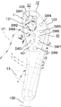
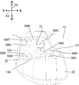
- FIG. 1 is a schematic perspective view showing an operating device for a work machine according to Embodiment 1.
- FIG. 2 is a schematic left side view of the work machine according to Embodiment 1.
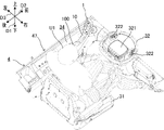
- FIG. 3 is a schematic perspective view and a partially enlarged view showing an operating section of the work machine according to Embodiment 1.
- FIG. 4 is a schematic perspective view showing a state in which a user is on the operating section of the work machine according to Embodiment 1.
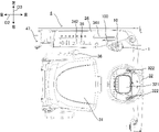
- FIG. FIG. 5 is a schematic front view showing an operating section of the work machine according to Embodiment 1.
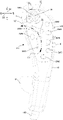
- FIG. FIG. 6 is a schematic plan view of the operating device for the work machine according to Embodiment 1, viewed from the operating surface side.
- FIG. 7 is a schematic right side view showing the operation device for the work machine according to Embodiment 1.
- FIG. 8 is a schematic top view showing the operating device for the work machine according to Embodiment 1.
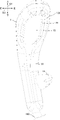
- FIG. 9 is a schematic plan view of the operating device for the work machine according to Embodiment 1 as seen from the back side.
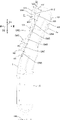
- FIG. 10 is a schematic plan view of another operating device for the work machine according to Embodiment 1, viewed from the back side.
- the work machine 4 includes a body 40 including a travel device 41 and the like.
- An operating device 1 (see FIG. 1) for a working machine according to the present embodiment is mounted on the body 40 of such a working machine 4. As shown in FIG.
- the "working machine” referred to in the present disclosure means a machine that performs various kinds of work in a work area such as a field F1, and examples thereof include harvesting machines (including combine harvesters), tractors, rice transplanters, spreaders, sprayers, They are work vehicles such as seeders and transplanters. That is, work machine 4 includes a work vehicle.
- the work machine 4 is not limited to a "vehicle”, and may be, for example, a work projectile or a work vessel. Further, the work machine 4 is not limited to agricultural machines (agricultural machines), and may be construction machines (construction machines), for example. In this embodiment, unless otherwise specified, the case where the working machine 4 is a riding-type harvesting machine will be described as an example.
- a “harvesting machine” as used in the present disclosure is a machine that performs crop harvesting in the field F1, and includes, for example, a combine (combine harvester) that performs threshing and sorting in addition to harvesting.
- the combine as the work machine 4 is mainly used for grain harvesting, and harvests crops while moving (running) in the field F1.
- there are two types of combine harvesters a general-purpose combine harvester that feeds the entire harvested crop into a threshing machine (threshing device 43) and a self-threshing type combine harvester that feeds only the tips of the harvested crop into the threshing machine.
- a self-throwing combine harvester will be described as an example of the work machine 4 .
- the work machine 4 is operated by a person (operator) (including remote control). machine.
- the “field” referred to in the present disclosure is an area where the work machine 4 performs harvesting work, and is, for example, a rice field, a field, or an orchard in which crops (agricultural products) to be harvested such as rice, wheat, soybeans, or buckwheat are grown. and pastures, etc.
- crops agricultural products
- crops agricultural products
- pastures etc.
- a case where the harvest target by the working machine 4 is "wheat" and the field F1 is an outdoor field where wheat is grown will be described.
- the vertical direction in which the work machine 4 is usable is defined as the vertical direction D1.
- the front-rear direction D2 and the left-right direction D3 are defined with reference to the direction viewed from the person (operator) riding (the operating section 47 of) the work machine 4 .
- the directions used in the present embodiment are defined with reference to the machine body 40 of the work machine 4.
- the direction in which the fuselage 40 moves when the machine 4 moves backward is “rear”.
- the direction in which the front end of the machine body 40 moves when the work machine 4 turns to the right is “right”
- the direction in which the front end of the machine body 40 moves when the work machine 4 turns to the left is “left”.
- these directions are not meant to limit the directions in which the work machine 4 is used (directions during use).
- the working machine 4 includes a harvesting device 42 , a threshing device 43 , a sorting device 44 , a storage device 45 , a power device 46 , an operation section 47 , and the like on the body 40 .
- the working machine 4 further includes a control device, a communication terminal, a fuel tank, a battery, and the like on the body 40 .
- the work machine 4 further includes an operating device 1 for the working machine (hereinafter also simply referred to as "operating device"). That is, the machine body 40, which is the main body of the work machine 4, includes a traveling device 41, a harvesting device 42, a threshing device 43, and the like.
- the operating device 1 configures the working machine 4 as a harvesting machine together with the machine body 40 .
- the harvesting machine (work machine 4 ) includes the operating device 1 for the work machine and the machine body 40 .
- the travel device 41 includes a crawler section and can move the working machine 4 in the front-rear direction D2 and the left-right direction D3.
- the work machine 4 performs harvesting while moving in the farm field F1.
- the work machine 4 may move in the farm field F1 while turning from the outside to the inside to the left. becomes.
- the reaping device 42 reaps crops (in this embodiment, wheat as an example) in field F1.
- the harvesting device 42 is arranged in front of the machine body 40 (see FIG. 2) of the working machine 4 and coupled to the machine body 40 .
- the harvesting device 42 forms part of the components of the work machine 4 .
- the reaping device 42 includes a plurality (seven as an example) of weed dividing plates 421, a triggering device 422, and a reaping blade (cutter).
- the reaping device 42 is a reaping device for “six-row reaping” capable of reaping six grain stalks at the same time.
- a plurality of weed dividing plates 421 are arranged side by side in the left-right direction D3 at the lower end portion on the front side of the reaping device 42 .
- a plurality of dividing plates 421 are inserted between crops (grain stalks) to define the width to cut the crops. Furthermore, the dividing plate 421 has a function of guiding the crops divided by the dividing plate 421 to the raising device 422 .
- the raising device 422 has raising tines for rectifying the crops, and performs a "raising operation” such as picking up lodged crops and converging the tips (tips) of the crops to a certain width.
- the hoisting device 422 rotates the chain provided with the hoisting tines to drive the hoisting tines and perform the hoisting work.
- the crops guided by the dividing plate 421 are raised by the raising device 422, and cut near the root portion by the cutting blade to be mowed. As a result, the crop is cut in the middle of the stalk, and the stalk including at least the tip is harvested by the working machine 4 .
- the stalks of crops harvested by the harvesting device 42 are conveyed to the threshing device 43 .
- the threshing device 43 threshes the crops (grain stalks) harvested by the harvesting device 42 .
- the threshing process separates the threshing containing grains from the culms.
- the threshing falls from the threshing device 43 to the sorting device 44 below.
- the sorting device 44 executes a sorting process of sorting out grains from the threshing that falls from the threshing device 43 .
- the sorting device 44 sorts out grains from the threshed grains by, for example, sieving the threshed grains while applying air to the threshed grains obliquely from below.
- the storage device 45 has a grain tank 451, a discharge auger 452, and the like.
- the grain tank 451 stores grains transported from the sorting device 44 by the transport conveyor. That is, the grains sorted by the sorting device 44 are transported to the grain tank 451 by the transport conveyor and stored in the grain tank 451 .
- the discharge auger 452 discharges grains in the grain tank 451 to an arbitrary location around the working machine 4 .
- the power unit 46 is a drive source for the traveling device 41, the harvesting device 42, the threshing device 43, the sorting device 44, the storage device 45, and the like.
- the power unit 46 has, for example, an engine such as a diesel engine as a power source.
- the power unit 46 may have a motor (electric motor) as a power source, or may have a hybrid power source including an engine and a motor.
- the driving unit 47 includes a driver's seat 31 (see FIG. 3) on which the user U1 (see FIG. 4) sits, a steering wheel 32 (see FIG. 3) operated by the user U1, various operation levers and various operation switches. etc. is provided.
- the operating device 1 according to the present embodiment is included in an operating system provided in the operating section 47 .
- the operating device 1 is provided in the operating section 47 and is operated by a user (operator) U1 who is on the operating section 47 .
- the driving unit 47 is of a cabin type having a cabin 471, and the user U1 boards in a cabin space inside the cabin 471. As shown in FIG.
- the operating device 1 is also arranged in the cabin space inside the cabin 471 .
- the operating unit 47 will be described in detail in the column "[2] Configuration of the operating unit", and the operating device 1 will be described in detail in the column “[3] Configuration of the operating device”.
- the control device controls the traveling device 41, the harvesting device 42, the threshing device 43, the sorting device 44, the storage device 45, the power device 46, etc. according to the operation received by the operating system including the operating device 1.
- the operation received by the operation device 1 includes an operation for moving (forward or backward) the aircraft 40, and the control device receives the operation for moving the operation device 1 forward.
- the travel device 41 is controlled to move the body 40 forward (forward).
- the control device controls the travel device 41 to move the machine body 40 backward (to move backward).
- the communication terminal communicates with a server or the like external to the work machine 4.
- the communication terminal is configured to indicate the operation status of the work machine 4, the current position of the work machine 4, the yield of the crop, the taste of the crop (including protein content or water content, etc.), the working time, or the working efficiency. etc., to a server or the like as appropriate.
- the communication terminal is configured to detect the current position of the work machine 4 using a satellite positioning system such as GNSS (Global Navigation Satellite System). Further, the communication terminal may receive control information related to driving assistance or automatic driving of the work machine 4 from a server or the like.
- GNSS Global Navigation Satellite System
- information (yield data) about the harvested amount can be obtained by detecting the amount of harvested grains with a sensor (grain sensor) provided in the work machine 4 .
- a sensor grain sensor
- this type of sensor includes an impact detection unit such as a strain gauge or a piezoelectric element attached to the upper surface of the grain tank 451, and when the grain transported toward the grain tank 451 collides with the impact detection unit to detect the impact force of
- the method of obtaining the yield of the work machine 4 is not limited to this.
- the work machine 4 configured as described above can cut the crops grown in the field F1 and thresh them to take out the grains by performing the reaping work while traveling in the field F1.
- FIG. 3 to 5 show only the main parts arranged in the cabin space inside the cabin 471 (see FIG. 2) in the operation part 47, and the other parts are omitted as appropriate. Furthermore, in FIGS. 3 to 5, illustration of the cabin 471 surrounding the cabin space is also omitted.
- the driving section 47 is arranged in front of the grain tank 451 (see FIG. 2) on the right side of the machine body of the work machine 4 . Further, the operating section 47 is positioned behind the harvesting device 42 and above the power device 46 (see FIG. 2). With such an arrangement, the user U1 gets on and off the driving section 47 from the right side of the driving section 47 . Therefore, in the present embodiment, the entrance/exit through which the user U1 passes is arranged on the right side (right side) of the driving unit 47 in one of the left and right directions D3. That is, the user U ⁇ b>1 gets on and off the driving unit 47 through the entrance opening on the right side of the driving unit 47 .
- the cabin 471 has a cabin frame, a cabin roof, a door (cabin door), and the like.
- the cabin frame is a structure as a skeleton of the cabin 471 and is formed so as to surround the cabin space.
- the cabin roof is arranged above the cabin frame and supported by the cabin frame.
- the door is provided at the entrance and is rotatable between a "closed position” covering the entrance and an "open position” opening the entrance so that the user U1 can pass through.
- the door body is supported by the cabin frame so as to be rotatable around the rotation axis.
- the door is arranged on the right side of the operation section 47, so the door is also arranged on the right side of the operation section 47.
- the door body may be of a "front-opening type" in which the front side in the front-rear direction D2 opens, or a "rear-opening type” in which the rear side opens.
- the cabin 471 further has various panel materials including a glass panel as a windshield. These various panel members are appropriately attached to both sides of the cabin frame in the front-rear direction D2 and both sides in the left-right direction D3, and surround the cabin space from all sides together with the door. Furthermore, the cabin roof (or cabin frame) is appropriately equipped with external components such as mirrors.
- the cabin type operation unit 47 including the cabin 471 as in the present embodiment at least the cabin frame functions as a skeleton of the cabin 471 and has sufficient strength ( rigidity). Also, the cabin 471 may be removable from the body of the work machine 4 .
- the operation unit 47 includes a display (monitor), gauges, etc., in addition to various operation systems including the driver's seat 31 and the steering wheel 32 .
- the driver's seat 31 , various operating systems, displays, instruments, and the like are all arranged in a cabin space within the cabin 471 .
- the driver's seat 31 is arranged facing forward in a substantially central portion of the cabin space in plan view (top view).
- the driver's seat 31 is configured such that the position (height) of the seat surface in the up-down direction D1 and the position in the front-rear direction D2 can be adjusted.
- the driver's seat 31 has foldable armrests on both sides in the left-right direction D3.
- the steering wheel 32 is arranged on a steering column 33 provided in front of the driver's seat 31 . Therefore, when the user U1 is seated on the driver's seat 31, the steering wheel 32 is positioned in front of the user U1 as shown in FIG.
- the handle 32 is rotatable with respect to the steering column 33 , and the control device turns the working machine 4 according to the rotation angle of the handle 32 .
- a display 321 for displaying the operating state of the work machine 4 is provided at the center of the handle 32 .
- the steering wheel 32 is provided with a steering switch 322 .
- a side column 34 is provided in the cabin space on the opposite side (left side) of the entrance/exit in the left-right direction D3 with respect to the driver's seat 31 .
- the operation device 1 as a main transmission lever, a work clutch lever 35, various switches, operation dials, and the like are arranged.
- the operating device 1 is arranged at a position near the front end of the side column 34 so as to be easily visible to the user U1 seated on the driver's seat 31. It is located behind the shift lever).
- the operation device 1 and the work clutch lever 35 both have a grip, and the user U1 grasps the grip and operates the operation device 1 or the work clutch lever 35 as a whole to move (including rotation and tilting).
- the operating device 1 has a shaft 100 and a body 10 supported by the tip (upper end) of the shaft 100, and the body 10 functions as a "grip". That is, the user U1 moves the entire operation device 1 including the shaft 100 by moving the body 10 in the front-rear direction D2 while gripping (gripping) the body 10, thereby operating the operation device 1. .
- a part of the surface of the body 10 constitutes an operation surface 101, on which an operation object 11 including a plurality of operators SW1, SW2, SW3, . . . is arranged.
- the operation target 11 will be described in detail in the section "[3] Configuration of operation device".
- the side column 34 is formed with a first slit 341 and a second slit 342 .
- the operating device 1 is configured such that the shaft 100 passes through the side column 34 through the first slit 341 in the vertical direction D1 and is movable along the first slit 341 .
- the work clutch lever 35 passes through the side column 34 in the vertical direction D ⁇ b>1 through the second slit 342 and is configured to be movable along the second slit 342 .
- the operating device 1 as the main gear lever is used to operate the traveling device 41 and the like, and as an example, moves (that is, switches) between a "forward position", a "reverse position", and a "neutral position”. , operated by user U1.
- the operation device 1 is movable in the front-rear direction D2, and the front end position of the movement range is the "forward position", the rear end position of the movement range is the “reverse position”, and the intermediate position of the movement range is the "neutral position”. position”.
- the control device stops the machine body 40 when the operating device 1 is in the "neutral position", and advances the machine body 40 when the operating device 1 moves from the "neutral position" to the "advance position" side (that is, forward).
- the control device adjusts the running speed steplessly according to the amount of operation of the operating device 1, that is, the amount of movement from the "neutral position". For example, the larger the amount of forward movement of the operating device 1 from the "neutral position", the faster the fuselage 40 moves forward.
- the work clutch lever 35 is used to operate the reaping device 42, the threshing device 43, etc., and as an example, is moved (that is, switched) between a "reaping position", a "threshing position", and an "OFF position". It is operated by user U1.
- the control device operates both the harvesting device 42 and the threshing device 43 when the work clutch lever 35 is in the "reaping position”, stops the harvesting device 42 and operates the threshing device 43 when it is in the "threshing position", If in the "OFF position", both the harvester 42 and the threshing device 43 are stopped.
- an auxiliary shift lever 36 is arranged between the driver's seat 31 and the side column 34, that is, on the left side of the driver's seat 31.
- the sub-transmission lever 36 is a lever-type operation tool used to switch the running speed of the machine body 40, and as an example, moves between a "raft position", a "working position” and a "neutral position". (that is, switch) is operated by the user U1.
- the control device sets the travel speed suitable for overpassing or loading and unloading of the work machine 4 onto and off the truck. 4. Set the traveling speed suitable for moving traveling.
- the operating device 1 as the main gear lever, the working clutch lever 35 and the auxiliary gear lever 36 are all located on one side of the driver's seat 31 in the left-right direction D3 (the left side in this embodiment). Therefore, the user U1 seated on the driver's seat 31 normally operates the operation device 1, the work clutch lever 35, and the sub-transmission lever 36 with the left hand.
- FIG. 1 and 6 to 9 the configuration of the operation device 1 of the working machine 4 according to the present embodiment will be described in more detail with reference to FIGS. 1 and 6 to 9.
- FIG. 1 and 6 to 9 only the operating device 1 is illustrated, and illustration of other configurations is omitted.
- the operating device 1 is a lever-type operating tool
- the posture (orientation, etc.) of the operating device 1 is appropriately changed by an operation (second operation) involving movement of the body 10 . Therefore, the posture of the operation device 1 can change as appropriate in the up-down direction D1, the front-rear direction D2, and the left-right direction D3 defined with the machine body 40 of the work machine 4 as a reference.
- FIGS. 6 to 9 it is assumed that the operating device 1 is in a state in which the longitudinal direction of the body 10 coincides with the vertical direction D1 and the operation surface 101 of the body 10 faces rearward. and explain.
- the operation device 1 is an operation device that is mounted on the body 40 of the work machine 4 and receives operations by the user U1.
- the operation device 1 includes a body 10 and an operation target 11, as shown in FIG.
- the body 10 includes an operation surface 101 on part of its surface.
- the operation target 11 is arranged on the operation surface 101 .
- the operation device 1 is configured to be able to receive a first operation including an operation on the operation target 11 and a second operation involving movement of the body 10 .
- the operation device 1 can accept at least two types of operations, a "first operation” and a "second operation", from the user U1. Therefore, the user U1 can perform at least two types of operations, a “first operation” and a “second operation”, using one operation device 1 .
- the operation surface 101 is provided on the surface of the body 10 on the side of the user U1 seated in the driver's seat 31, that is, on the rearward facing portion (rear surface).
- the operation surface 101 is a flat plane here, the operation surface 101 is not limited to a flat surface, and may include, for example, a curved surface or a step.
- the operation target 11 includes a plurality of operators SW1 to SW9.
- the operation target 11 includes nine operators SW1 to SW9 made up of various types of mechanical switches such as push button switches, joysticks, and seesaw switches. That is, in this embodiment, the operation target 11 includes a plurality of types of operators SW1 to SW9. In the operation target 11, these plural (nine in this embodiment) operators SW1 to SW9 are configured to be individually operable.
- the "first operation” including the operation on the operation target 11 includes a plurality of types of operations on the individual operators SW1 to SW9, such as an operation on the operator SW1 and an operation on the operator SW2.
- the operation device 1 has a circuit board inside the body 10, and when a first operation (that is, operations on the plurality of operators SW1 to SW9) on the operation target 11 is received from the user U1, 1 Outputs an electric signal according to the operation. For example, when the user U1 presses the operator SW4, which is a push button switch, the operating device 1 outputs an electric signal indicating that the operator SW4 has been operated.
- the "second operation" involving the movement of the body 10 includes operations for advancing and retreating the traveling device 41 and adjusting the traveling speed as described above. That is, in the present embodiment, since the operation device 1 is a lever-type operation tool used as a main shift lever, the body 10 is moved between the "forward position", the "reverse position” and the "neutral position". The operation can be accepted as a "second operation". Therefore, for example, when receiving a second operation from the user U1 that involves moving the body 10 from the "neutral position" to the "advance position" side (that is, forward), the operation device 1 responds to the operation amount of the second operation. The controller is caused to control the travel device 41 so as to move the machine body 40 forward at the travel speed.
- the operating device 1 is normally operated with the left hand of the user U1 seated on the driver's seat 31, as described above.
- the user U1 operates the operation device 1 while holding the body 10 with the left hand with the thumb (first finger) on the front side of the body 10, that is, on the operation surface 101 side. (including the first operation and the second operation).
- the fingers other than the thumb of the user U1's left hand that is, the index finger (second finger), middle finger (third finger), ring finger (fourth finger), and little finger (fifth finger)
- the user U1 operates the individual operators SW1 to SW9 with the thumb of the left hand.
- the user U1 moves the body 10 gripped with the left hand in the front-rear direction D2.
- the user U1 operates the operation device 1 while holding the body 10 with one hand (the left hand in this embodiment). It is shaped like a grip having a length in the direction D1. More specifically, the body 10 does not have uniform dimensions in the left-right direction D3, and is configured to have smaller (thinner) dimensions in the left-right direction D3 toward the lower portion closer to the shaft 100 in the up-down direction D1. In other words, the upper portion of the body 10 is configured to be relatively wide in the left-right direction D3, and the dimension of the operation surface 101 in the width direction (left-right direction D3) is ensured. Further, the operating device 1 includes a hand rest 13 projecting leftward from the lower portion of the body 10 . The handrest 13 receives the weight of the left hand of the user U1, thereby reducing the fatigue of the user U1 in a state of gripping the body 10. - ⁇
- An operator (stick operator) SW1 composed of a joystick is an operator for operating an automatic horizontal control (UFO) that keeps the airframe 40 horizontal in the horizontal direction.
- the operation element SW2, which is a seesaw switch, is an operation element for adjusting the threshing depth. The threshing depth is reduced by pushing the left end.
- the operation element SW3, which is a seesaw switch, is an operation element for manually raising and lowering the reaper 42. As an example, when the upper end of the operation element SW3 is pushed, the reaper 42 is lowered and the operation element The reaping device 42 is lifted by pushing the lower end of SW3.
- An operating element SW4 consisting of a push button switch is an operating element for changing the speed of the reaping device 42.
- FIG. An operator SW5, which is a push button switch is an operator for forcibly operating the feed chain.
- An operator SW6, which is a push button switch is an auto lift switch for raising the harvesting device 42 to a set position.
- An operator SW7, which is a push button switch is an auto-set switch for lowering the reaper 42 to the auto-set height.
- An operating element SW8, which is a push button switch is an operating element for shifting the sub-shift.
- An operator SW9, which is a push button switch is a spare button.
- the plurality of operators SW1 to SW9 are dispersedly arranged on the operation surface 101 in the vertical direction D1 and the horizontal direction D3.
- the operator SW1 is arranged at the upper left corner of the operation surface 101
- the operator SW2 is arranged below the operator SW1
- the operator SW3 is arranged below the operator SW2.
- four operators SW4 to SW7 are arranged in the vertical direction D1 in the order of operators SW4, SW5, SW6 and SW7 from above.
- the operator SW8 is disposed below the operator SW3 and the operator SW7 on the operation surface 101 and between the operator SW3 and the operator SW7 in the horizontal direction D3.
- the operator SW9 is arranged on the operation surface 101 at a position surrounded by the operators SW2 and SW3, that is, at a position below the operator SW2 and to the left of the operator SW3.
- the operators SW2 and SW3 which are seesaw switches, are particularly frequently operated. Placed in a position that is relatively easy to operate.
- these manipulators SW2 and SW3 are arranged so that the thumb of the left hand of the user U1 who operates the manipulators SW2 and SW3 can be easily reached from the center of the operation surface 101 in the left-right direction D3 toward the left end. This makes it easier to operate the operators SW2 and SW3 than at least the operators SW4 to SW7 positioned to the right of the operators SW2 and SW3.
- the operating elements SW2 and SW3, which are seesaw switches, are also oriented in consideration of the operability of the user U1. That is, the manipulator SW2 positioned relatively on the upper side is arranged such that its manipulation direction (longitudinal direction) is aligned with the left-right direction D3.
- the manipulator SW3 positioned relatively on the lower side is arranged such that its operating direction (longitudinal direction) is aligned with the vertical direction D1. More specifically, the operator SW2 is arranged to the left so that the right end of the operator SW2 is located above the operator SW3. In addition, the operator SW2 is inclined with respect to the left-right direction D3 so that the right end is located slightly lower than the left end.
- the operators SW2 and SW3 are arranged along a virtual circle C1 centered at the virtual point P1 (only a part of the circumference is shown in FIG. 6), as shown in FIG. .
- the user U1 positions the base of the thumb of the left hand near the virtual point P1 and rotates the thumb with the base of the thumb as a fulcrum, thereby arranging the tip of the thumb along the trajectory (virtual circle C1).
- the manipulators SW2 and SW3 are operable with the tip of the thumb. That is, the user U1 moves the tip of the thumb along the virtual circle C1 so as to slide the tip of the thumb on the manipulators SW2 and SW3 while touching the operation device 1.
- the operators SW2 and SW3 can be operated. As a result, the user U1 can easily operate the operators SW2 and SW3 without looking at the operation device 1, thereby improving operability.
- some of the operators SW5, SW8, and SW9 protrude from the operation surface 101 so as to prevent erroneous operation of the other operators SW4 to SW9 when the operators SW2 and SW3 are operated. set small. That is, as shown in FIG. 7, the projection amount H1 of the operation element SW8 and the like from the operation surface 101 is the projection amount H2 of the operation element SW7 and the like from the operation surface 101, and the projection amount of the operation element SW3 and the like from the operation surface 101. It is smaller than H3, etc. (H1 ⁇ H2 ⁇ H3).
- the manipulators SW5, SW8, and SW9 have the same amount of protrusion from the manipulation surface 101, and are the smallest among the plurality of manipulators SW1 to SW9.
- the manipulators SW5, SW8, and SW9 which are set to have a small protrusion amount, are positioned on the trajectory of the thumb when manipulating the manipulators SW2 and SW3.
- the operator SW5 is positioned on the right side of the extension line of the operation direction (horizontal direction D3) of the operator SW2, and the operator SW8 is positioned downward on the extension line of the operation direction (vertical direction D1) of the operator SW3.
- the manipulator SW9 is positioned at the base of the thumb.
- the amount of protrusion of the operators SW5, SW8, and SW9 on the orbit of the thumb that is, the height when the operation surface 101 is used as a reference, is kept lower than the others, so that the operators SW2 and SW3 can be operated. Erroneous operation of SW5, SW8, and SW9 is less likely to occur.
- the operation device 1 may face the operation surface 101 with the palm of the user U1 during an operation (second operation) for moving the body 11 itself, such as a forward operation.
- second operation when the user U1 holds (grabs) the body 10 from above with the palm of the left hand facing downward, the palm of the left hand faces the operation surface 101 .
- the operation device 1 according to the present embodiment employs the following configuration so that even if the user U1 operates the body 10 in this state, the operation target 11 arranged on the operation surface 101 is unlikely to be erroneously operated. .
- the operating device 1 further includes an erroneous operation prevention section 12 projecting from the operating surface 101 as shown in FIG.
- the erroneous operation prevention unit 12 is formed integrally with the body 10 so as to protrude rearward from the operation surface 101 facing the user U1 side (rearward). That is, in the present embodiment, the erroneous operation prevention section 12 is integrated with the body 10 so as to be seamlessly continuous.
- the body 10, the operation target 11, the erroneous operation prevention unit 12, the handrest 13, etc. are all made of resin, but not limited to this, at least a part of which is made of metal or the like. may be
- the erroneous operation preventing section 12 makes it difficult for the operation target 11 to be erroneously operated.
- the erroneous operation prevention unit 12 protrudes from the operation surface 101, even if the user U1 operates the body 10 with the user U1's palm or the like facing the operation surface 101, the user U1's palm or the like and the operation surface 101 do not move. 101, a gap is ensured by the erroneous operation prevention unit 12. As shown in FIG.
- the palm of the user U1 or the like is less likely to touch the operation target 11 arranged on the operation surface 101, and an erroneous operation in which the operation target 11 is operated unintentionally by the user U1 is less likely to occur.
- the operating device 1 according to the present embodiment it is possible to realize the operating device for the working machine and the working machine 4 that can easily prevent erroneous operation.
- the erroneous operation prevention section 12 includes wall sections 121 , 122 and 123 arranged along the outer periphery of the operation surface 101 . That is, the erroneous operation prevention portion 12 is a wall-shaped (or rib-shaped) portion having a length along the outer circumference of the operation surface 101 .
- the erroneous operation prevention unit 12 includes a wall portion 121 located on the left side of the operation surface 101 (left side) and a wall portion located above the operation surface 101 (upper side). 122 and a (right) wall portion 123 located on the right side of the operation surface 101 .
- These three walls 121 , 122 , 123 are provided so as to be seamlessly continuous along the outer circumference of the operation surface 101 .
- Walls 121, 122, 123 have a thickness sufficient to achieve the desired strength.
- Each of the walls 121 , 122 , 123 is configured such that the inner side surface facing the operation surface 101 when viewed from the front thereof rises substantially vertically from the outer peripheral edge of the operation surface 101 .
- the outer surfaces of the walls 121 , 122 , 123 opposite to the operation surface 101 when viewed from the front are flush with the outer surface of the body 10 .
- the erroneous operation prevention unit 12 can easily secure a gap between the palm of the user U 1 and the operation surface 101 over a wide range of the operation surface 101 . erroneous operation can be effectively prevented.
- the walls 121 , 122 , 123 are arranged only on a part of the outer periphery of the operation surface 101 .
- the walls 121, 122, and 123 are not arranged over the entire circumference of the outer circumference of the operation surface 101, but are partially arranged on the outer circumference of the operation surface 101 of the walls 121, 122, and 123 in the circumferential direction. placed.
- the outer periphery of the operation surface 101 has a portion where the walls 121, 122 and 123 are arranged and a portion where the walls 121, 122 and 123 are not arranged.
- the (left) wall portion 121 is arranged along the left side of the operation surface 101
- the (upper) wall portion 122 is arranged along the upper side of the operation surface 101
- the (right) wall portion 123 is arranged along the operation surface. It is arranged along the right side of 101 . Therefore, no wall portion is provided on the lower side of the operation surface 101, and the operation surface 101 is configured to open downward. Thereby, the operability of the operation target 11 arranged on the operation surface 101 is improved as compared with the case where the entire outer circumference of the operation surface 101 is surrounded by the walls 121 , 122 , and 123 .
- the erroneous operation prevention portions 12 are arranged at least at both ends of the operation surface 101 in the width direction (left-right direction D3). Projection amounts H11 and H12 of the erroneous operation preventing portion 12 from the operation surface 101 are larger at a portion located farther from the user U1 in the width direction (horizontal direction D3) of the operation surface 101 than at a portion located closer to the user U1. big.
- the erroneous operation prevention unit 12 includes the (left) wall 121 , the (upper) wall 122 and the (right) wall 123 . It is positioned at both ends in the width direction (horizontal direction D3). Projection amounts H11 and H12 of these wall portions 121, 122, and 123 from the operation surface 101, that is, the height when the operation surface 101 is used as a reference are not uniform and differ depending on the part.
- the wall portion 121 positioned farther from the user U1 seated in the driver's seat 31, that is, on the left side in the left-right direction D3, is It is higher than the wall portion 123 located on the near side, that is, on the right side in the left-right direction D3. That is, in FIG. 7, the projection amount H12 of the wall portion 123 located on the front side (right side) of the page with respect to the operation switch SW1 is the projection amount H11 of the wall portion 121 located on the rear side of the page surface (left side) with respect to the operation switch SW1. less than (H11>H12).
- the amount of protrusion of the wall portion 121 or the wall portion 123 is also not constant, in FIG.
- the amount of protrusion H11 of the erroneous operation prevention section 12 from the operation surface 101 is larger than the amount of protrusion H4 of the operation target 11 from the operation surface 101 (H11>H4).
- the projection amount H11 of the (upper) wall portion 122 is the largest among the plurality of wall portions 121 , 122 , and 123 . Therefore, the protrusion amount H11 of the erroneous operation prevention portion 12 from the operation surface 101 is defined by the protrusion amount H11 of the wall portion 122 .
- the protrusion amount H4 of the manipulator SW1 is the largest among the plurality of manipulators SW1 to SW9 (H4>H3).
- the projection amount H4 of the operation target 11 from the operation surface 101 is defined by the projection amount H4 of the operation element SW1.
- the amount of protrusion H11 of the erroneous operation prevention section 12 from the operation surface 101 is larger than any of the plurality of operators SW1 to SW9. According to this configuration, when the erroneous operation prevention unit 12 contacts the palm of the user U1, etc., it becomes easier to secure a gap between the operation target 11 (the plurality of manipulators SW1 to SW9) and the palm of the user U1. , erroneous operation of the operation target 11 can be efficiently prevented.
- the operation target 11 includes the joystick type operator SW1 (stick operator).
- the operating element SW1 has a stick 14 (see FIG. 6) protruding from the operating surface 101 and receives an operation such as tilting the stick 14 .
- the operator SW1 is arranged in the upper left corner of the operation surface 101 surrounded by the (left) wall 121 and the (upper) wall 122 .
- the operation target 11 includes a stick operator (manipulator SW1) that is operated to tilt the stick 14 protruding from the operation surface 101 .
- the erroneous operation prevention unit 12 is arranged around the stick operator (operator SW1) so as to surround the stick operator (operator SW1) from at least two directions.
- the erroneous operation prevention unit 12 surrounds the operator SW1 with the (left) wall 121 from the left side, and surrounds the operator SW1 with the (upper) wall 122 from above. According to this configuration, the erroneous operation prevention unit 12 efficiently prevents an erroneous operation of the manipulator SW1 due to the user U1's hand touching the stick 14 unintentionally and the stick 14 tilting.
- the operating device 1 has a hook portion 15 on the body 10 as shown in FIG.
- the hook portion 15 is provided on the rear surface 102 of the body 10 facing away from the operation surface 101 .
- the operation surface 101 faces the user U1 seated in the driver's seat 31, that is, faces backward, so the back surface 102 faces the opposite side of the user U1 seated in the driver seat 31, that is, faces forward.
- the hook 15 has a shape and size that can be hooked by the finger of the user U1. Specifically, when the user U1 grips the body 10 with the left hand (see FIG. 1), at least one of the index finger, the middle finger, the ring finger and the little finger of the left hand is hooked on the hook portion 15 .
- the body 10 has a hook portion 15 on the back surface 102 on the side opposite to the operation surface 101, on which the fingers of the user U1 can be hooked.
- the user U1 grips the body 10
- the user's fingers are caught, making it easier to grip the body 10 even with one hand.
- the user U1 can operate the operation target 11 with the thumb while the index finger or the like is hooked on the hook 15, so that the position of the base of the thumb, which is the fulcrum of the thumb, is stable, and an erroneous operation occurs. become difficult.
- the user U1 can grip the body 10 with his or her index finger or the like hooked on the hook 15. Therefore, even when the body 10 is moved backward, the body 10 can be completely removed from the hand. It is less likely to come off, and less likely to be erroneously operated.
- the hook portion 15 has a length in the longitudinal direction of the body 10 .
- the body 10 has a length in the vertical direction D1. Therefore, the hook portion 15 is also configured to have a length in the vertical direction D1. That is, body 10 has a length.
- the hook portion 15 extends along the longitudinal direction of the body 10 (vertical direction D1).
- the user U1 can use the hook portion 15 as a guide when moving the left hand while the index finger or the like is hooked on the hook portion 15 .
- the user U1 can stably move the left hand in the longitudinal direction of the body 10 by sliding the index finger or the like hooked on the hook 15 in the longitudinal direction of the hook 15. can be done. Therefore, for example, when the user U1 moves the base of the thumb during the first operation, the position and posture of the left hand are stabilized, and erroneous operations are less likely to occur.
- the hook portion 15 protrudes from the back surface 102 .
- the central portion of the back surface 102 located on the back side of the operation surface 101 protrudes from the back surface 102 in a raised manner to form the hook portion 15 .
- the hooking portion 15 is the portion that is one step higher than the back surface 102 due to the step 151 , that is, the portion that is surrounded by the step 151 and protrudes one step forward from the back surface 102 . That is, in the present embodiment, the hook portion 15 is integrated with the body 10 so as to be seamlessly continuous. As a result, the hooking portion 15 can be provided without narrowing the internal space of the body 10 , and it is easy to secure a space for accommodating a circuit board or the like in the body 10 .
- the configuration related to the arrangement of the operation target 11 (the plurality of operators SW1 to SW9), the configuration related to the erroneous operation prevention section 12, and the configuration related to the hook section 15 can be adopted independently.
- the operating device 1 may omit the hook portion 15 and employ only the erroneous operation prevention portion 12 , or conversely, omit the erroneous operation prevention portion 12 and employ only the hook portion 15 .
- the operation device 1 may omit the erroneous operation prevention section 12 and the hook section 15 and employ only a configuration related to the arrangement of the operation target 11 (the plurality of operators SW1 to SW9).
- the body 10 may be configured so that the orientation of the operation surface 101 can be changed. Specifically, as shown in FIG. 10, the tip (upper end) of the shaft 100 is inserted into the body 10 so that the body 10 can swing (rotate) about the central axis of the shaft 100. It is supported by the shaft 100 in a state of being folded.
- the body 10 is fixed to the shaft 100 with one or more (two in FIG. 10) fixing screws 103 .
- the shaft 100 is formed with a plurality of (three in FIG. 10) fixing holes 104a, 104b, and 104c that are displaced from one fixing screw 103 in the swinging direction of the body 10 (the circumferential direction of the shaft 100). ing.
- FIG. 10 the tip (upper end) of the shaft 100 is inserted into the body 10 so that the body 10 can swing (rotate) about the central axis of the shaft 100. It is supported by the shaft 100 in a state of being folded.
- the body 10 is fixed to the shaft 100 with one or more (two in
- the shaft 100 is formed with a total of six fixing holes 104a, 104b, 104c.
- Each fixing screw 103 is fixed to one of the plurality of fixing holes 104a, 104b, 104c. Therefore, depending on which one of the plurality of fixing holes 104a, 104b, 104c each fixing screw 103 is fixed, the mounting angle of the body 10 with respect to the shaft 100 changes, and the orientation of the operation surface 101 changes. That is, in the example of FIG. 10, since three fixing holes 104a, 104b, and 104c are provided for one fixing screw 103, the orientation of the operation surface 101 can be changed in three steps.
- the orientation (angle) of the operation surface 101 with respect to the user U1 can be changed, so that the operability for the user U1 can be improved.
- the orientation of the operation surface 101 is not limited to the example of FIG. 10, and may be changeable in two steps, four steps or more, or steplessly.
- the work machine 4 is not limited to a self-throwing combine harvester, and may be a normal combine harvester or a harvesting machine other than a combine harvester. Furthermore, the working machine 4 may be an agricultural machine other than a harvesting machine, a construction machine, or the like.
- the harvesting target by the work machine 4 is not limited to "wheat", and is not limited to grains.
- the reaping device 42 is not limited to "6-row cutting", and may be, for example, 2-row cutting, 3-row cutting, 4-row cutting, 5-row cutting, or 7-row cutting.
- the erroneous operation prevention section 12 includes the walls 121, 122, and 123 arranged along the outer periphery of the operation surface 101, and the erroneous operation prevention section 12 may have, for example, a plurality of dowel-like projections in place. It may be a configuration arranged in.
- the walls 121 , 122 , and 123 are not limited to a part of the outer circumference of the operation surface 101 , and may be provided on the entire outer circumference of the operation surface 101 (entire circumference).
- the amounts H11 and H12 of the erroneous operation prevention portion 12 projecting from the operation surface 101 may be uniform regardless of the part.
- the amount H11 of protrusion of the erroneous operation prevention section 12 from the operation surface 101 may be equal to or less than the amount H4 of protrusion of the operation target 11 from the operation surface 101 .
- the stick operator (operator SW1) does not have to be arranged so as to surround the stick operator (operator SW1) from at least two directions.
- the driving unit 47 is not limited to the cabin type, and may be, for example, a canopy type or a floor type. That is, the types of the operation unit 47 of the work machine 4 such as a combine harvester include a cabin type, a canopy type, a floor type, and the like.
- the cabin-type operation unit 47 includes the cabin 471 as described above, and the user U1 rides in the cabin space inside the cabin 471.
- the canopy-type operation unit 47 includes a canopy (roof).
- the user U1 boards in the space below the .
- the floor-type driving section 47 does not include a cabin 471, a canopy, etc., and the user U1 rides in a space opened upward.
- the entrance/exit of the driving unit 47 is not limited to being arranged on the right side (right side) of the driving unit 47 as in the first embodiment.
- the entrance/exit may be arranged on the left side (left side) of the operation section 47 or on both sides in the left-right direction D3.
- the operation target 11 is not limited to a push button switch, a joystick, and a seesaw switch, and may include a mechanical switch such as a rotary switch, a slide switch, or a toggle switch. .
- the operation target 11 may include an operator other than a mechanical switch, such as a touch sensor (touch switch) that does not include a movable part.
- the operation target 11 is not limited to a switch, and may include, for example, a variable resistor or an encoder.
- assignment of operations to the plurality of operators SW1 to SW9 is not limited to the example described above. Furthermore, it is not essential that the operation target 11 includes nine operators SW1 to SW9, and the operation target 11 may include one to eight operators, or nine or more operators. good.
- the erroneous operation prevention section 12 does not have to be integrated with the body 10 .
- the erroneous operation prevention section 12, which is separate from the body 10 may be attached to the body 10 by a fastener such as a screw or an adhesive.
- the hook portion 15 does not have to be integrated with the body 10 .
- the hook portion 15 that is separate from the body 10 may be attached to the body 10 by a fastener such as a screw or by adhesion.
- the hook portion 15 does not have to extend along the longitudinal direction of the body 10 (vertical direction D1).
- the hook portion 15 is not limited to a shape protruding from the rear surface 102, and may be, for example, a concave portion such as a groove or a hole.
Landscapes
- Life Sciences & Earth Sciences (AREA)
- Engineering & Computer Science (AREA)
- Environmental Sciences (AREA)
- Mechanical Engineering (AREA)
- Chemical & Material Sciences (AREA)
- Combustion & Propulsion (AREA)
- Transportation (AREA)
- Soil Sciences (AREA)
- Harvester Elements (AREA)
- Arrangement Or Mounting Of Control Devices For Change-Speed Gearing (AREA)
Abstract
作業機械用の操作装置(1)は、作業機械の機体に搭載され、ユーザ(U1)による操作を受け付ける操作装置であって、ボディ(10)と、操作対象(11)と、を備える。ボディ(10)は、表面の一部に操作面(101)を含む。操作対象(11)は、操作面(101)に配置されている。操作装置(1)は、操作対象(11)に対する操作を含む第1操作と、ボディ(10)の移動を伴う第2操作と、を受付可能に構成されている。操作装置(1)は、操作面(101)から突出する誤操作防止部(12)を更に備える。
Description
本発明は、作業機械用の操作装置、及び作業機械に関する。
関連技術として、キャビン内に主変速レバー等の操作装置を備える作業機械(コンバイン)が知られている(例えば、特許文献1参照)。関連技術に係る作業機械においては、主変速レバーは、ユーザ(作業者)が左手で握るボディ(グリップ)を有し、例えば、前進増速時に運転席に対し左斜前方に移動させるようにボディが操作される。さらに、関連技術においては、主変速レバーは、ボディの操作面(上面)に刈取変速スイッチ及び副変速スイッチ等の各種スイッチを有しており、操作面を運転席のユーザ側に傾けるように配置されている。ユーザは、主変速レバーの各種スイッチを、主として左手の親指で操作する。
上記関連技術の構成では、ボディの握り方によっては、例えば、前進増速時等のボディ自体を移動させる操作時に、ユーザの手のひら等が各種スイッチに触れるなどして、ユーザが意図せずに各種スイッチが操作される誤操作につながる可能性がある。
本発明の目的は、誤操作を防止しやすい作業機械用の操作装置、及び作業機械を提供することにある。
本発明の一態様に係る作業機械用の操作装置は、作業機械の機体に搭載され、ユーザによる操作を受け付ける操作装置であって、ボディと、操作対象と、を備える。前記ボディは、表面の一部に操作面を含む。前記操作対象は、前記操作面に配置されている。前記操作装置は、前記操作対象に対する操作を含む第1操作と、前記ボディの移動を伴う第2操作と、を受付可能に構成されている。前記操作装置は、前記操作面から突出する誤操作防止部を更に備える。
本発明の一態様に係る作業機械は、前記作業機械用の操作装置と、前記操作装置が搭載される機体と、を備える。
本発明によれば、誤操作を防止しやすい作業機械用の操作装置、及び作業機械を提供することができる。
以下、添付図面を参照しながら、本発明の実施形態について説明する。以下の実施形態は、本発明を具体化した一例であって、本発明の技術的範囲を限定する趣旨ではない。
(実施形態1)
[1]全体構成
まず、本実施形態に係る作業機械4の全体構成について、図2を参照して説明する。作業機械4は、走行装置41等を含む機体40を備えている。本実施形態に係る作業機械用の操作装置1(図1参照)は、このような作業機械4の機体40に搭載される。
[1]全体構成
まず、本実施形態に係る作業機械4の全体構成について、図2を参照して説明する。作業機械4は、走行装置41等を含む機体40を備えている。本実施形態に係る作業機械用の操作装置1(図1参照)は、このような作業機械4の機体40に搭載される。
本開示でいう「作業機械」は、例えば圃場F1等の作業領域において各種の作業を行う機械を意味し、一例として、収穫機械(コンバインを含む)、トラクタ、田植機、散布機、噴霧機、播種機及び移植機等の作業車両である。つまり、作業機械4は作業車両を含む。作業機械4は、「車両」に限らず、例えば、作業用飛翔体又は作業用船舶等であってもよい。さらに、作業機械4は農業機械(農機)に限らず、例えば、建設機械(建機)等であってもよい。本実施形態では、特に断りが無い限り、作業機械4が乗用タイプの収穫機械である場合を例に挙げて説明する。
本開示でいう「収穫機械」は、圃場F1にて作物の収穫作業を行う機械であって、一例として、収穫作業に加えて脱穀及び選別を行うコンバイン(コンバインハーベスタ)等を含む。作業機械4としてのコンバインは、主として穀物の収穫作業に用いられ、圃場F1内を移動(走行)しながら、作物の刈り取りを行い、刈り取った作物を収穫する。特に、コンバインには、刈り取った作物全体を脱穀機(脱穀装置43)に送り込む普通型(汎用)コンバインと、刈り取った作物の穂先のみを脱穀機に送り込む自脱型コンバインとがあるところ、本実施形態では、自脱型コンバインを作業機械4の例として説明する。また、本実施形態では一例として、作業機械4は、人(オペレータ)の操作(遠隔操作を含む)により動作することとするが、これに限らず、作業機械4は、自動運転により動作する無人機であってもよい。
本開示でいう「圃場」は、作業機械4が収穫作業を行う領域であって、例えば、稲、麦、大豆又はそば等の収穫対象となる作物(農産物)を生育する田んぼ、畑、果樹園及び牧草地等を含む。本実施形態では一例として、作業機械4による収穫対象が「小麦」であって、圃場F1が小麦を生育する屋外の畑である場合を例に挙げて説明する。
また、本実施形態では、説明の便宜上、作業機械4が使用可能な状態での鉛直方向を上下方向D1と定義する。さらに、作業機械4(の運転部47)に乗っている人(オペレータ)から見た方向を基準として、前後方向D2及び左右方向D3を定義する。言い換えれば、本実施形態で用いられる各方向は、いずれも作業機械4の機体40を基準として規定される方向であって、作業機械4の前進時に機体40が移動する方向が「前方」、作業機械4の後退時に機体40が移動する方向が「後方」となる。同様に、作業機械4の右旋回時に機体40の前端部が移動する方向が「右方」、作業機械4の左旋回時に機体40の前端部が移動する方向が「左方」となる。ただし、これらの方向は、作業機械4の使用方向(使用時の方向)を限定する趣旨ではない。
作業機械4は、走行装置41に加えて、刈取装置42、脱穀装置43、選別装置44、貯留装置45、動力装置46及び運転部47等を、機体40に備えている。本実施形態では、作業機械4は、制御装置、通信端末、燃料タンク及びバッテリ等を、機体40に更に備えている。また、本実施形態では、作業機械4は、作業機械用の操作装置1(以下では単に「操作装置」ともいう)を更に備えている。すなわち、作業機械4の本体である機体40は、走行装置41、刈取装置42及び脱穀装置43等を含んでいる。そして、本実施形態に係る操作装置1は、機体40と共に、収穫機械としての作業機械4を構成する。言い換えれば、本実施形態に係る収穫機械(作業機械4)は、作業機械用の操作装置1と、機体40と、を備えている。
走行装置41は、クローラ部を含み、作業機械4を前後方向D2及び左右方向D3に移動させることができる。例えば、作業機械4は、圃場F1内を移動しながら収穫作業を実施する。一例として、作業機械4は、圃場F1内を外側から内側に向かって左に旋回しながら移動してもよく、この場合、作業機械4の移動軌跡は平面視において反時計回りの渦巻き状の経路となる。
刈取装置42は、圃場F1の作物(本実施形態では一例として小麦)を刈り取る。刈取装置42は、作業機械4の機体40(図2参照)の前方に配置され、機体40に結合されている。刈取装置42が機体40に備わった状態では、刈取装置42は作業機械4の構成要素の一部を成す。
刈取装置42は、複数(一例として7つ)の分草板421と、引起装置422と、刈刃(カッター)と、を備えている。本実施形態一例として、刈取装置42は、6条分の穀稈を同時に刈り取ることが可能な「6条刈」の刈取装置である。
複数の分草板421は、刈取装置42の前面側の下端部に、左右方向D3に並べて配置されている。複数の分草板421は、作物(穀稈)と作物(穀稈)との間に差し込まれることにより、作物を刈り取るべき幅を規定する。さらに、分草板421は、分草板421により分けられた作物を、引起装置422へ案内する機能を有する。
引起装置422は、作物を整流するための引起タインを有しており、倒伏した作物を拾い上げたり、作物の先端(穂先)を一定の幅に収束させたりする「引起し作業」を行う。具体的には、引起装置422は、引起タインが設けられたチェーンを回転させることにより、引起タインを駆動して引起し作業を実施する。分草板421により案内された作物は、引起装置422により引き起こされ、刈刃によって根本部付近が切断されて刈り取られる。これにより、作物は穀稈の途中で切断されることになり、少なくとも穂先を含む穀稈が作業機械4によって刈り取られることになる。刈取装置42で刈り取られた作物の穀稈は、脱穀装置43に搬送される。
脱穀装置43は、刈取装置42により刈り取られた作物(穀稈)に対する脱穀処理を実行する。脱穀処理では、穀稈から穀粒を含む脱穀物を分離する。脱穀物は脱穀装置43から下方の選別装置44へ落下する。
選別装置44は、脱穀装置43から落下する脱穀物から、穀粒を選別する選別処理を実行する。選別装置44は、例えば、脱穀物に対して斜め下方から風を当てつつ脱穀物をふるいにかけることにより、脱穀物から穀粒を選別する。
貯留装置45は、グレンタンク451及び排出オーガ452等を有する。グレンタンク451は、搬送コンベアにより選別装置44から搬送される穀粒を貯留する。つまり、選別装置44で選別された穀粒は、搬送コンベアにてグレンタンク451まで搬送され、グレンタンク451に貯留される。排出オーガ452は、グレンタンク451内の穀粒を作業機械4の周囲の任意の場所へ排出する。
動力装置46は、走行装置41、刈取装置42、脱穀装置43、選別装置44及び貯留装置45等の駆動源である。動力装置46は、動力源として、例えばディーゼルエンジン等のエンジンを有する。また、動力装置46は、動力源としてモータ(電動機)を有していてもよいし、エンジンとモータとを含むハイブリッド式の動力源を有していてもよい。
運転部47には、ユーザU1(図4参照)が着席する運転座席31(図3参照)、並びに、ユーザU1により操作されるハンドル32(図3参照)、各種の操作レバー及び各種の操作スイッチ等の操作系が設けられている。本実施形態に係る操作装置1は、運転部47に設けられる操作系に含まれている。つまり、操作装置1は、運転部47に設けられており、運転部47に搭乗したユーザ(オペレータ)U1によって操作される。本実施形態では一例として、運転部47は、キャビン471を備えるキャビンタイプであって、キャビン471の内部のキャビン空間にユーザU1が搭乗する。そのため、操作装置1についても、キャビン471の内部のキャビン空間に配置される。運転部47について詳しくは「[2]運転部の構成」の欄で説明し、操作装置1について詳しくは「[3]操作装置の構成」の欄で説明する。
制御装置は、操作装置1を含む操作系が受け付ける操作に応じて、走行装置41、刈取装置42、脱穀装置43、選別装置44、貯留装置45及び動力装置46等を制御する。本実施形態では一例として、操作装置1が受け付ける操作には機体40を移動(前進又は後退)させるための操作が含まれており、制御装置は、操作装置1が前進のための操作を受け付けた場合に走行装置41を制御して機体40を前進(前方に移動)させる。さらに、操作装置1が後退のための操作を受け付けた場合には、制御装置は走行装置41を制御して機体40を後退(後方に移動)させる。
通信端末は、作業機械4の外部のサーバ等と通信を行う。ここでは、通信端末は、作業機械4の稼働状況、作業機械4の現在位置、作物の収穫量(収量)、作物の食味(タンパク質含有量又は水分含有量等を含む)、作業時間又は作業効率等に関する情報を、サーバ等に適宜送信する。本実施形態では、通信端末は、例えばGNSS(Global Navigation Satellite System)等の衛星測位システムを用いて、作業機械4の現在位置を検出可能に構成されている。また、通信端末は、作業機械4の運転支援又は自動運転等に係る制御情報をサーバ等から受信してもよい。一例として、収穫量に関する情報(収量データ)は、作業機械4に備わっているセンサー(穀粒センサー)により、収穫された穀粒量を検出することで取得可能である。この種のセンサーは、一例として、グレンタンク451の上面に取り付けられる歪みゲージ又は圧電素子等の衝撃検出部を含み、グレンタンク451へ向けて搬送された穀粒が、衝撃検出部に衝突した際の衝撃力を検出する。もちろん、作業機械4の収穫量の取得手法は、これに限定されない。
上記のように構成される作業機械4は、圃場F1内を走行しながら刈取作業を行うことで、圃場F1に生育されている作物を刈り取り、脱穀して穀粒を取り出すことができる。
[2]運転部の構成
次に、本実施形態に係る作業機械4の運転部47の構成について、図2~図5を参照して説明する。図3~図5では、運転部47におけるキャビン471(図2参照)の内部のキャビン空間に配置される主要部のみを図示し、それ以外の図示を適宜省略する。さらに、図3~図5では、キャビン空間を囲んでいるキャビン471の図示も省略する。
次に、本実施形態に係る作業機械4の運転部47の構成について、図2~図5を参照して説明する。図3~図5では、運転部47におけるキャビン471(図2参照)の内部のキャビン空間に配置される主要部のみを図示し、それ以外の図示を適宜省略する。さらに、図3~図5では、キャビン空間を囲んでいるキャビン471の図示も省略する。
本実施形態では、運転部47は、作業機械4の機体の右側部分におけるグレンタンク451の前方(図2参照)に配置されている。さらに、運転部47は、刈取装置42の後方であって、かつ動力装置46の上方(図2参照)に位置する。このような配置により、ユーザU1は運転部47の右側から、運転部47に対して乗り降りすることになる。そのため、本実施形態では、ユーザU1が通る乗降口は、運転部47における左右方向D3の一方である右方(右側)に配置されている。つまり、ユーザU1は、運転部47の右側に開口した乗降口を通って、運転部47に搭乗し、また、運転部47から降りることになる。
キャビン471は、キャビンフレーム、キャビンルーフ及び扉体(キャビンドア)等を有している。キャビンフレームは、キャビン471の骨格としての構造体であって、キャビン空間を囲むように形成されている。キャビンルーフは、キャビンフレームの上方に配置され、キャビンフレームによって支持される。扉体は、乗降口に設けられており、乗降口を覆う「閉位置」と、ユーザU1が通過可能な状態に乗降口を開放する「開位置」との間で回転可能である。扉体は、回転軸を中心に回転可能な状態でキャビンフレームに支持されている。本実施形態では、乗降口が運転部47の右側に配置されているので、扉体についても運転部47の右側に配置される。扉体は、前後方向D2の前側が開く「前開きタイプ」と、後側が開く「後開きタイプ」とのいずれであってもよい。
また、キャビン471は、フロントガラスとしてのガラスパネルを含む各種のパネル材を更に有している。これら各種のパネル材は、キャビンフレームの前後方向D2の両側及び左右方向D3の両側に適宜取り付けられており、扉体と共にキャビン空間を四方から囲んでいる。さらに、キャビンルーフ(又はキャビンフレーム)には、ミラー等の外装品が適宜装着される。本実施形態のようにキャビン471を備えるキャビンタイプの運転部47においては、少なくともキャビンフレームが、キャビン471の骨格としての機能を有し、キャビンルーフ及び扉体等を支持するのに十分な強度(剛性)を有している。また、キャビン471は作業機械4の機体から取り外し可能であってもよい。
運転部47は、運転座席31、及びハンドル32を含む各種の操作系に加えて、ディスプレイ(モニタ)及び計器類等を備えている。これら運転座席31、各種の操作系、ディスプレイ及び計器類等は、いずれもキャビン471内のキャビン空間に配置されている。
具体的には、運転座席31は、平面視(上面視)においてキャビン空間の略中央部に、前方に向けて配置されている。運転座席31は、座面の上下方向D1の位置(高さ)及び前後方向D2の位置を調節可能に構成されている。運転座席31は、左右方向D3の両側に、折り畳み可能に構成されたアームレストを有している。ハンドル32は、運転座席31の前方に設けられたステアリングコラム33上に配置されている。したがって、ユーザU1が運転座席31に着座した状態では、図4に示すように、ユーザU1の正面にハンドル32が位置する。ハンドル32はステアリングコラム33に対して回転可能であって、ハンドル32の回転角度に応じて制御装置は作業機械4を旋回させる。また、ハンドル32の中央部には、作業機械4の動作状態等を表示するディスプレイ321が設けられている。さらに、ハンドル32にはステアリングスイッチ322が設けられている。
キャビン空間のうち、運転座席31に対して左右方向D3の乗降口とは反対側(左側)には、サイドコラム34が設けられている。サイドコラム34の上面には、主変速レバーとしての操作装置1、作業クラッチレバー35、各種スイッチ及び操作ダイヤル等が配置されている。ここで、操作装置1は、運転座席31に着座したユーザU1の視界に入りやすいように、サイドコラム34の前端部寄りの位置に配置されており、作業クラッチレバー35は、操作装置1(主変速レバー)の後方に配置されている。
操作装置1及び作業クラッチレバー35は、いずれもグリップを有し、ユーザU1がグリップを握って操作装置1又は作業クラッチレバー35全体を移動(回転及び傾倒を含む)させるように操作する、レバータイプの操作具である。例えば、操作装置1は、図3に示すように、シャフト100と、シャフト100の先端部(上端部)に支持されているボディ10と、を有し、ボディ10が「グリップ」として機能する。つまり、ユーザU1は、ボディ10を握った(掴んだ)状態で、ボディ10を前後方向D2に移動させることにより、シャフト100を含めた操作装置1全体を移動させて、操作装置1を操作する。さらに、ボディ10の表面の一部は操作面101を構成し、操作面101には複数の操作子SW1,SW2,SW3…を含む操作対象11が配置されている。操作対象11について詳しくは「[3]操作装置の構成」の欄で説明する。
本実施形態では、サイドコラム34には、第1スリット341及び第2スリット342が形成されている。操作装置1は、シャフト100が第1スリット341を通してサイドコラム34を上下方向D1に貫通し、第1スリット341に沿って移動可能に構成されている。作業クラッチレバー35は、第2スリット342を通してサイドコラム34を上下方向D1に貫通し、第2スリット342に沿って移動可能に構成されている。
ここで、主変速レバーとしての操作装置1は、走行装置41等の操作に使用され、一例として、「前進位置」と「後進位置」と「中立位置」との間を移動する(つまり切り替える)ように、ユーザU1によって操作される。本実施形態では、操作装置1は前後方向D2に移動可能であって、移動範囲の前端位置が「前進位置」、移動範囲の後端位置が「後進位置」、移動範囲の中間位置が「中立位置」である。制御装置は、操作装置1が「中立位置」にあれば機体40を停止させ、「中立位置」から「前進位置」側(つまり前方)に操作装置1が移動すると機体40を前進させ、「中立位置」から「後進位置」側(つまり後方)に操作装置1が移動すると機体40を後退(後進)させる。さらに、制御装置は、操作装置1の操作量、つまり「中立位置」からの移動量に応じて、走行速度を無段階で調節する。例えば、「中立位置」から前方への操作装置1の移動量が大きくなるほど、機体40が高速で前進する。
作業クラッチレバー35は、刈取装置42及び脱穀装置43等の操作に使用され、一例として、「刈取位置」と「脱穀位置」と「OFF位置」との間を移動する(つまり切り替える)ように、ユーザU1によって操作される。制御装置は、作業クラッチレバー35が「刈取位置」にあれば刈取装置42及び脱穀装置43の両方を作動させ、「脱穀位置」にあれば刈取装置42を停止させて脱穀装置43を作動させ、「OFF位置」にあれば刈取装置42及び脱穀装置43の両方を停止させる。
さらに、運転座席31とサイドコラム34との間、つまり運転座席31の左側には、副変速レバー36が配置されている。副変速レバー36は、機体40の走行速度の切り替えに使用されるレバータイプの操作具であって、一例として、「畦越位置」と「作業位置」と「中立位置」との間を移動する(つまり切り替える)ように、ユーザU1によって操作される。制御装置は、副変速レバー36が「畦越位置」にあれば畦越え又はトラックへの作業機械4の積み降ろしに適した走行速度に設定し、「作業位置」にあれば刈取作業及び作業機械4の移動走行に適した走行速度に設定する。
主変速レバーとしての操作装置1、作業クラッチレバー35及び副変速レバー36は、いずれも運転座席31に対して左右方向D3の一方側(本実施形態では左側)にある。そのため、運転座席31に着座したユーザU1は、通常、左手で操作装置1、作業クラッチレバー35及び副変速レバー36を操作することになる。
[3]操作装置の構成
次に、本実施形態に係る作業機械4の操作装置1の構成について、図1,図6~図9を参照してより詳細に説明する。図1,図6~図9では、操作装置1のみを図示し、その他の構成の図示を省略している。
次に、本実施形態に係る作業機械4の操作装置1の構成について、図1,図6~図9を参照してより詳細に説明する。図1,図6~図9では、操作装置1のみを図示し、その他の構成の図示を省略している。
また、本実施形態では、操作装置1はレバータイプの操作具であるので、ボディ10の移動を伴う操作(第2操作)により、操作装置1の姿勢(向き等)が適宜変化する。したがって、作業機械4の機体40を基準として規定される上下方向D1、前後方向D2及び左右方向D3に対しては、操作装置1の姿勢は適宜変化し得る。以下では、図6~図9に示すように、操作装置1の姿勢が、ボディ10の長手方向が上下方向D1に一致し、かつボディ10の操作面101が後方を向いた状態にあると仮定して説明する。
本実施形態に係る操作装置1は、作業機械4の機体40に搭載され、ユーザU1による操作を受け付ける操作装置である。操作装置1は、図1に示すように、ボディ10と、操作対象11と、を備えている。ボディ10は、表面の一部に操作面101を含む。操作対象11は、操作面101に配置されている。操作装置1は、操作対象11に対する操作を含む第1操作と、ボディ10の移動を伴う第2操作と、を受付可能に構成されている。要するに、操作装置1は、ユーザU1から、少なくとも「第1操作」と「第2操作」との2種類の操作を受付可能である。そのため、ユーザU1は、1つの操作装置1を用いて、少なくとも「第1操作」と「第2操作」との2種類の操作を行うことができる。
本実施形態では一例として、操作面101は、ボディ10の表面のうち、運転座席31に着座したユーザU1側、つまり後方を向いた部位(背面)に設けられている。ここでは、操作面101は平坦な平面であるが、操作面101は平面に限らず、例えば、湾曲面又は段差等を含んでいてもよい。
ここで、操作対象11は、複数の操作子SW1~SW9を含んでいる。本実施形態では一例として、操作対象11は、押釦スイッチ、ジョイスティック及びシーソスイッチ等の様々な種類のメカニカルスイッチからなる9つの操作子SW1~SW9を含んでいる。つまり、本実施形態では、操作対象11は、複数種類の操作子SW1~SW9を含んでいる。操作対象11においては、これら複数(本実施形態では9つ)の操作子SW1~SW9は個別に操作可能に構成されている。
つまり、操作対象11に対する操作を含む「第1操作」には、操作子SW1に対する操作、及び操作子SW2に対する操作等、個々の操作子SW1~SW9に対する複数種類の操作が含まれている。本実施形態では、操作装置1は、ボディ10の内部に回路基板を有しており、ユーザU1から操作対象11に対する第1操作(つまり複数の操作子SW1~SW9に対する操作)を受け付けると、第1操作に応じた電気信号を出力する。例えば、ユーザU1が押釦スイッチからなる操作子SW4を押操作すると、操作装置1は、操作子SW4が操作されたことを表す電気信号を出力する。
一方、ボディ10の移動を伴う「第2操作」には、上述したような走行装置41の前進、後退及び走行速度の調節のための操作が含まれる。つまり、本実施形態では、操作装置1は、主変速レバーとして用いられるレバータイプの操作具であるので、ボディ10を「前進位置」と「後進位置」と「中立位置」との間で移動させる操作を「第2操作」として受付可能である。そのため、操作装置1は、例えば、ユーザU1より「中立位置」から「前進位置」側(つまり前方)へのボディ10の移動を伴う第2操作を受け付けると、第2操作の操作量に応じた走行速度で機体40を前進させるよう、制御装置に走行装置41を制御させる。
本実施形態に係る操作装置1は、上述したように、通常、運転座席31に着座したユーザU1の左手で操作される。一般的には、ユーザU1は、図1に示すように、親指(第一指)をボディ10の手前側、つまり操作面101側として、左手でボディ10を握った状態で操作装置1の操作(第1操作及び第2操作を含む)を行う。このとき、ユーザU1の左手の親指以外の指、つまり人差し指(第二指)、中指(第三指)、薬指(第四指)及び小指(第五指)は、ボディ10における操作面101とは反対側の裏面102(図7参照)側に位置する。この状態で、「第1操作」を行う際には、ユーザU1は、左手の親指にて個々の操作子SW1~SW9を操作する。「第2操作」を行う際には、ユーザU1は、左手で握ったボディ10を前後方向D2に移動させる。
このように、ユーザU1はボディ10を片手(本実施形態では左手)で握った状態で操作装置1を操作するので、ボディ10は、人が片手で掴むことができるサイズであって、かつ上下方向D1に長さを有するグリップ状に形成されている。より詳細には、ボディ10は、左右方向D3の寸法が均一ではなく、上下方向D1においてシャフト100側となる下部ほど、左右方向D3の寸法が小さく(細く)構成されている。つまり、ボディ10の上部は、左右方向D3において比較的幅広に構成されており、操作面101の幅方向(左右方向D3)の寸法が確保される。さらに、操作装置1は、ボディ10の下部から左方に突出するハンドレスト13を備えている。ハンドレスト13は、ユーザU1の左手の重量を受けることで、ボディ10を握った状態のユーザU1の疲労を軽減する。
本実施形態では一例として、操作対象11に含まれる複数の操作子SW1~SW9には、それぞれ以下の操作が割り当てられている。ジョイスティックからなる操作子(スティック操作子)SW1は、機体40を左右水平に維持する自動水平制御(UFO)の操作用の操作子である。シーソスイッチからなる操作子SW2は、こぎ深さを調節するための操作子であって、一例として、操作子SW2の右端部が押操作されることでこぎ深さを深くし、操作子SW2の左端部が押操作されることでこぎ深さを浅くする。シーソスイッチからなる操作子SW3は、刈取装置42を手動で昇降させるための操作子であって、一例として、操作子SW3の上端部が押操作されることで刈取装置42を下降させ、操作子SW3の下端部が押操作されることで刈取装置42を上昇させる。押釦スイッチからなる操作子SW4は、刈取装置42の変速のための操作子である。押釦スイッチからなる操作子SW5は、強制的にフィードチェンを作動させるための操作子である。押釦スイッチからなる操作子SW6は、刈取装置42を設定位置まで上昇させるためのオートリフトスイッチである。押釦スイッチからなる操作子SW7は、刈取装置42をオートセット高さまで下降させるためのオートセットスイッチである。押釦スイッチからなる操作子SW8は、副変速を変速するための操作子である。押釦スイッチからなる操作子SW9は、予備ボタンである。
これら複数の操作子SW1~SW9は、図6に示すように、操作面101において、上下方向D1及び左右方向D3に分散して配置されている。具体的には、操作子SW1が操作面101の左上隅に配置され、操作子SW1の下方に操作子SW2が配置され、操作子SW2の下方に操作子SW3が配置されている。操作面101の右端部には、4つの操作子SW4~SW7が、上方から操作子SW4,SW5,SW6,SW7の順で上下方向D1に並べて配置されている。操作子SW8は、操作面101のうち、操作子SW3及び操作子SW7の下方であって、左右方向D3における操作子SW3及び操作子SW7の間の位置に配置されている。操作子SW9は、操作面101のうち、操作子SW2及び操作子SW3で囲まれた位置、つまり操作子SW2の下方であって操作子SW3の左方となる位置に配置されている。
本実施形態に係る作業機械4においては、複数の操作子SW1~SW9のうちシーソスイッチからなる操作子SW2,SW3の操作頻度が特に高いため、これら操作子SW2,SW3については操作面101の中でも比較的操作しやすい位置に配置される。つまり、これら操作子SW2,SW3は、操作子SW2,SW3を操作するユーザU1の左手の親指が届きやすいように、左右方向D3における操作面101の中心から左端部に偏って配置されている。これにより、少なくとも操作子SW2,SW3より右側に位置する操作子SW4~SW7に比較すると、操作子SW2,SW3が操作しやすくなる。
さらに、シーソスイッチからなる操作子SW2,SW3は、その向きについても、ユーザU1の操作性を考慮した向きを採用している。つまり、相対的に上側に位置する操作子SW2は、その操作方向(長手方向)が左右方向D3に沿うような向きで配置されている。相対的に下側に位置する操作子SW3は、その操作方向(長手方向)が上下方向D1に沿うような向きで配置されている。より詳細には、操作子SW2の右端部が操作子SW3の上方に位置するように、特に操作子SW2が左方寄りに配置されている。その上で、操作子SW2は、右端部が左端部に比べてやや下方に位置するように、左右方向D3に対して傾斜して配置されている。これにより、操作子SW2,SW3は、図6に示すように、仮想点P1を中心とする仮想円C1(図6では円周の一部のみを図示)に沿って、配置されることになる。
したがって、ユーザU1においては、左手の親指の付根を仮想点P1近傍に位置させ、付根を支点に親指を回転させるように動かすことで、親指の先端部の軌道(仮想円C1)に沿って配置されている操作子SW2,SW3を、親指の先端部にて操作可能となる。つまり、ユーザU1は、仮想円C1に沿って親指の先端部を動かすことにより、親指の先端部を、操作装置1に触れさせたまま操作子SW2,SW3上を滑らせるように移動させて、操作子SW2,SW3を操作することができる。その結果、ユーザU1は、操作装置1を目視せずとも操作子SW2,SW3を操作しやすくなり、操作性が向上する。
また、本実施形態では、操作子SW2,SW3の操作時に、他の操作子SW4~SW9の誤操作が生じにくいように、一部の操作子SW5,SW8,SW9の操作面101からの突出量が小さく設定されている。すなわち、図7に示すように、操作面101からの操作子SW8等の突出量H1は、操作面101からの操作子SW7等の突出量H2、操作面101からの操作子SW3等の突出量H3等よりも小さい(H1<H2<H3)。操作子SW5,SW8,SW9の操作面101からの突出量は同一であって、複数の操作子SW1~SW9の中で最小である。これらの突出量が小さく設定された操作子SW5,SW8,SW9は、操作子SW2,SW3の操作時の親指の軌道上に位置する。つまり、操作子SW5は操作子SW2の操作方向(左右方向D3)の延長線上である右方に位置し、操作子SW8は操作子SW3の操作方向(上下方向D1)の延長線上である下方に位置する。操作子SW9は親指の付根側に位置する。これら親指の軌道上の操作子SW5,SW8,SW9の突出量、つまり操作面101を基準にしたときの高さが、他よりも低く抑えられることで、操作子SW2,SW3の操作時に操作子SW5,SW8,SW9の誤操作が生じにくい。
ところで、操作装置1は、ボディ10の握り方によっては、例えば、前進操作等のボディ11自体を移動させる操作(第2操作)時において、ユーザU1の手のひら等が操作面101と対向する場合がある。具体的には、ユーザU1が、第2操作に際して、左手の手のひらを下方に向けた状態でボディ10を上方から鷲掴みするように握る(掴む)と、左手の手のひらが操作面101に対向する。本実施形態に係る操作装置1は、この状態でユーザU1がボディ10を操作しても、操作面101に配置された操作対象11の誤操作が生じにくいように、下記の構成を採用している。
すなわち、本実施形態に係る操作装置1は、図1に示すように、操作面101から突出する誤操作防止部12を更に備えている。本実施形態では一例として、誤操作防止部12は、ユーザU1側(後方)を向いた操作面101から後方に突出するように、ボディ10と一体に形成されている。つまり、本実施形態では、誤操作防止部12は、ボディ10とシームレスに連続するように一体化されている。また、本実施形態では一例として、ボディ10、操作対象11、誤操作防止部12及びハンドレスト13等は、いずれも樹脂製であることとするが、これに限らず、少なくとも一部が金属製等であってもよい。
この構成によれば、操作装置1は、たとえユーザU1の手のひら等が操作面101と対向するようにボディ10を握られたとしても、誤操作防止部12によって操作対象11の誤操作が生じにくい。要するに、誤操作防止部12が操作面101から突出していることで、ユーザU1の手のひら等が操作面101と対向した状態でユーザU1がボディ10を操作しても、ユーザU1の手のひら等と操作面101との間には、誤操作防止部12にて隙間が確保される。したがって、操作面101に配置されている操作対象11には、ユーザU1の手のひら等が触れにくくなり、ユーザU1が意図せずに操作対象11が操作される誤操作が生じにくくなる。結果的に、本実施形態に係る操作装置1によれば、誤操作を防止しやすい作業機械用の操作装置、及び作業機械4を実現可能である。
以下、誤操作防止部12の構成について更に詳しく説明する。
本実施形態では、誤操作防止部12は、操作面101の外周に沿って配置される壁部121,122,123を含む。つまり、誤操作防止部12は、操作面101の外周に沿って長さを有する壁状(又はリブ状)の部位である。本実施形態では、図1及び図6に示すように、誤操作防止部12は、操作面101の左側に位置する(左側)壁部121と、操作面101の上側に位置する(上側)壁部122と、操作面101の右側に位置する(右側)壁部123と、を含んでいる。これら3つの壁部121,122,123は、操作面101の外周に沿ってシームレスに連続するように設けられている。壁部121,122,123は、所望の強度を実現するだけの厚みを有している。各壁部121,122,123は、操作面101を正面から見て操作面101側となる内側面が、操作面101の外周縁から略垂直に立ち上がるように構成されている。さらに、各壁部121,122,123は、操作面101を正面から見て操作面101と反対側となる外側面が、ボディ10の外側面と面一である。このような壁部121,122,123を有することで、誤操作防止部12は、操作面101の広範囲にわたってユーザU1の手のひら等と操作面101との間の隙間を確保しやすくなり、操作対象11の誤操作を効率的に防止できる。
また、壁部121,122,123は、操作面101の外周部の一部にのみ配置されている。すなわち、壁部121,122,123は、操作面101の外周における周方向の全周にわたって配置されるのではなく、壁部121,122,123の操作面101の外周における周方向の一部に配置される。言い換えれば、操作面101の外周には、壁部121,122,123が配置される部位と、壁部121,122,123が配置されない部位とが生じる。本実施形態では、(左側)壁部121が操作面101の左辺に沿って配置され、(上側)壁部122が操作面101の上辺に沿って配置され、(右側)壁部123が操作面101の右辺に沿って配置される。したがって、操作面101の下辺には壁部が設けられておらず、操作面101は下方に向けて開放された構成となる。これにより、操作面101の外周全周が壁部121,122,123で囲まれる場合に比べて、操作面101に配置されている操作対象11の操作性がよくなる。
また、図7に示すように、誤操作防止部12は、少なくとも操作面101の幅方向(左右方向D3)の両端に配置されている。操作面101からの誤操作防止部12の突出量H11,H12は、操作面101の幅方向(左右方向D3)においてユーザU1から見て遠い側に位置する部位で、近い側に位置する部位よりも大きい。本実施形態では、誤操作防止部12は、(左側)壁部121、(上側)壁部122及び(右側)壁部123を含むので、このうち壁部121及び壁部123は、操作面101の幅方向(左右方向D3)の両端に位置する。そして、これらの壁部121,122,123の操作面101からの突出量H11,H12、つまり操作面101を基準にしたときの高さは、一律ではなく、部位によって異なる。
具体的には、図7及び図8に示すように、運転座席31に着座した状態のユーザU1から見て遠い側、つまり左右方向D3の左側に位置する壁部121は、ユーザU1から見て近い側、つまり左右方向D3の右側に位置する壁部123よりも高い。つまり、図7において、操作子SW1に対して紙面手前側にある(右側)壁部123の突出量H12は、操作子SW1に対して紙面奥側にある(左側)壁部121の突出量H11より小さい(H11>H12)。ここで、壁部121又は壁部123の突出量も一定ではないため、図7では操作子SW1の左右方向D3の両側において、壁部121及び壁部123の突出量H11,H12を規定している。この構成によれば、ユーザU1から見て操作面101の手前側においては、誤操作防止部12の突出量(高さ)が抑えられるため、誤操作防止部12による操作面101の視認性の低下を抑えることができる。
また、図7に示すように、誤操作防止部12の操作面101からの突出量H11は、操作対象11の操作面101からの突出量H4よりも大きい(H11>H4)。ここで、(上側)壁部122の突出量H11は、複数の壁部121,122,123の中で最大である。そのため、誤操作防止部12の操作面101からの突出量H11は、壁部122の突出量H11にて規定される。同様に、操作子SW1の突出量H4は、複数の操作子SW1~SW9の中で最大である(H4>H3)。そのため、操作対象11の操作面101からの突出量H4は、操作子SW1の突出量H4にて規定される。つまり、誤操作防止部12の操作面101からの突出量H11は、複数の操作子SW1~SW9のいずれよりも大きい。この構成によれば、誤操作防止部12がユーザU1の手のひら等に接触することで、操作対象11(複数の操作子SW1~SW9)とユーザU1の手のひら等との間の隙間を確保しやすくなり、操作対象11の誤操作を効率的に防止できる。
また、本実施形態では、上述したように、操作対象11はジョイスティックタイプの操作子SW1(スティック操作子)を含んでいる。この操作子SW1は、操作面101から突出するスティック14(図6参照)を有し、スティック14を傾けるような操作を受け付ける。そして、操作子SW1は、操作面101のうち(左側)壁部121と(上側)壁部122とで囲まれた左上隅に配置されている。要するに、操作対象11は、操作面101から突出するスティック14を傾けるように操作されるスティック操作子(操作子SW1)を含む。誤操作防止部12は、スティック操作子(操作子SW1)の周囲にスティック操作子(操作子SW1)を少なくとも2方向から囲むように配置されている。つまり、本実施形態では、誤操作防止部12は、操作子SW1を左方からは(左側)壁部121で囲み、操作子SW1を上方からは(上側)壁部122で囲んでいる。この構成によれば、ユーザU1が意図せずにユーザU1の手がスティック14に触れてスティック14が傾くことによる操作子SW1の誤操作が、誤操作防止部12にて効率的に防止される。
ところで、本実施形態に係る操作装置1は、図9に示すように、ボディ10に引掛部15を有している。引掛部15は、ボディ10のうち操作面101とは反対側を向いた裏面102に設けられている。本実施形態では、操作面101は運転座席31に着座したユーザU1側、つまり後方を向いているので、裏面102は運転座席31に着座したユーザU1とは反対側、つまり前方を向いた面である。引掛部15は、ユーザU1の手指を引っ掛けることが可能な形状及びサイズを有している。具体的には、ユーザU1は、左手でボディ10を握る際(図1参照)、左手の人差し指、中指、薬指及び小指の少なくとも1本を、引掛部15に引っ掛けるようにする。
すなわち、本実施形態では、ボディ10は、操作面101とは反対側の裏面102に、ユーザU1の手指を引っ掛けることが可能な引掛部15を有する。これにより、ユーザU1がボディ10を握る際に、手指の引っ掛かりが生じるので、片手であってもボディ10を握りやすくなる。そして、第1操作に際しては、ユーザU1は、引掛部15に人差し指等を引っ掛けた状態で、親指にて操作対象11を操作できるので、親指の支点となる付根の位置が安定し、誤操作が生じにくくなる。さらに、第2操作に際しては、ユーザU1は、引掛部15に人差し指等を引っ掛けた状態でボディ10を握ることができるので、特にボディ10を後方に移動させるときでも、手からボディ10がすっぽ抜けるようなことが生じにくく、誤操作が生じにくくなる。
また、引掛部15は、ボディ10の長手方向に長さを有している。本実施形態では、上述したようにボディ10は上下方向D1に長さを有している。そのため、引掛部15についても、上下方向D1に長さを有するように構成されている。すなわち、ボディ10は長さを有している。引掛部15は、ボディ10の長手方向(上下方向D1)に沿って延長されている。これにより、ユーザU1は、引掛部15に人差し指等を引っ掛けた状態で、左手を動かす際に引掛部15をガイドとして利用することができる。具体的には、ユーザU1は、引掛部15に引っ掛けた人差し指等を、引掛部15の長手方向に滑らせるようにして移動させることで、左手をボディ10の長手方向に安定的に移動させることができる。したがって、例えば、第1操作に際して、ユーザU1が親指の付根の位置を移動させる場合などにおいて、左手の位置及び姿勢が安定し、誤操作が生じにくくなる。
また、本実施形態では、引掛部15は、裏面102から突出する。具体的には、図7及び図9に示すように、操作面101の裏側に位置する裏面102の中央部が、盛り上がるように裏面102から突出することで、引掛部15を構成している。図7及び図9であれば、段差151により裏面102から一段高くなっている部分、つまり段差151に囲まれて裏面102から一段前方に突出している部分が、引掛部15となる。つまり、本実施形態では、引掛部15は、ボディ10とシームレスに連続するように一体化されている。これにより、ボディ10の内部空間を狭めることなく引掛部15を設けることができ、ボディ10内の回路基板等の収容スペースを確保しやすい。
ところで、操作装置1に関して、操作対象11(複数の操作子SW1~SW9)の配置等に係る構成、誤操作防止部12に係る構成、及び引掛部15に係る構成は、それぞれ独立して採用可能である。つまり、例えば、操作装置1は、引掛部15が省略され、誤操作防止部12のみを採用してもよいし、反対に、誤操作防止部12が省略され、引掛部15のみを採用してもよい。同様に、操作装置1は、誤操作防止部12及び引掛部15が省略されて、操作対象11(複数の操作子SW1~SW9)の配置等に係る構成のみを採用してもよい。
また、操作装置1に関して、ボディ10は、操作面101の向きを変更可能に構成されていてもよい。具体的には、図10に示すように、ボディ10は、シャフト100の中心軸を支点に首振り(回転)可能となるように、シャフト100の先端部(上端部)がボディ10に差し込まれた状態でシャフト100に支持される。ここで、ボディ10は、1以上(図10では2つ)の固定ねじ103にて、シャフト100に対して固定される。シャフト100には、1つの固定ねじ103に対して、ボディ10の首振り方向(シャフト100の周方向)に位置ずれした複数(図10では3つ)の固定孔104a,104b,104cが形成されている。図10では、固定ねじ103が2つ設けられているので、シャフト100には計6つの固定孔104a,104b,104cが形成されている。各固定ねじ103は、これら複数の固定孔104a,104b,104cのうちのいずれか1つに対して固定される。そのため、各固定ねじ103が複数の固定孔104a,104b,104cのいずれに固定されるかによって、シャフト100に対するボディ10の取り付け角度が変化し、操作面101の向きが変更される。つまり、図10の例では、1つの固定ねじ103に対して固定孔104a,104b,104cが3つ設けられているので、操作面101の向きは3段階で変更可能である。
この構成によれば、ユーザU1に対する操作面101の向き(角度)を変更できるので、ユーザU1にとっての操作性の向上を図ることができる。ただし、図10の例に限らず、例えば、操作面101の向きは2段階、又は4段階以上で変更可能であってもよいし、無段階で変更可能であってもよい。
[4]変形例
以下、実施形態1の変形例を列挙する。以下に説明する変形例は、適宜組み合わせて適用可能である。
以下、実施形態1の変形例を列挙する。以下に説明する変形例は、適宜組み合わせて適用可能である。
作業機械4は、自脱型コンバインに限らず、普通型コンバインであってもよいし、コンバイン以外の収穫機械であってもよい。さらに、作業機械4は、収穫機械以外の農業機械、又は建設機械等であってもよい。作業機械4による収穫対象は、「小麦」に限らず、更には穀物にも限らない。刈取装置42は、「6条刈」に限らず、例えば、2条刈、3条刈、4条刈、5条刈又は7条刈等であってもよい。
また、誤操作防止部12が、操作面101の外周に沿って配置される壁部121,122,123を含むことは必須ではなく、誤操作防止部12は、例えば、複数のダボ状の突起が適所に配置された構成であってもよい。また、壁部121,122,123は、操作面101の外周部の一部に限らず、操作面101の外周部の全体(全周)に設けられていてもよい。また、操作面101からの誤操作防止部12の突出量H11,H12は、部位によらず均一であってもよい。また、誤操作防止部12の操作面101からの突出量H11は、操作対象11の操作面101からの突出量H4以下であってもよい。また、スティック操作子(操作子SW1)の周囲にスティック操作子(操作子SW1)を少なくとも2方向から囲むように配置されていなくてもよい。
また、運転部47は、キャビンタイプに限らず、例えば、キャノピータイプ又はフロアタイプ等であってもよい。すなわち、コンバイン等の作業機械4の運転部47の種類としては、キャビンタイプ、キャノピータイプ及びフロアタイプ等がある。キャビンタイプの運転部47は、上述のようにキャビン471を備え、キャビン471の内部のキャビン空間にユーザU1が搭乗するのに対し、キャノピータイプの運転部47は、キャノピー(屋根)を備え、キャノピーの下方の空間にユーザU1が搭乗する。フロアタイプの運転部47は、キャビン471及びキャノピー等を備えておらず、上方に開放された空間にユーザU1が搭乗する。
また、運転部47の乗降口は、実施形態1のように、運転部47の右方(右側)に配置される構成に限らない。例えば、乗降口は、運転部47の左方(左側)、又は、左右方向D3の両側に配置されてもよい。
また、操作対象11は、ユーザU1の操作を受け付ける構成であればよく、押釦スイッチ、ジョイスティック及びシーソスイッチに限らず、例えば、ロータリスイッチ、スライドスイッチ又はトグルスイッチ等のメカニカルスイッチを含んでいてもよい。操作対象11は、例えば、可動部を含まないタッチセンサ(タッチスイッチ)等、メカニカルスイッチ以外の操作子を含んでいてもよい。さらに、操作対象11は、スイッチに限らず、例えば、可変抵抗器又はエンコーダ等を含んでいてもよい。
また、複数の操作子SW1~SW9への操作の割り当ては、上述した例に限らない。さらに、操作対象11が操作子SW1~SW9を9つ含むことも必須ではなく、操作対象11は、1つ以上8つ以下の操作子を含んでもよいし、9つ以上の操作子を含んでもよい。
また、誤操作防止部12はボディ10と一体化されていなくてもよい。例えば、ボディ10とは別体の誤操作防止部12が、ねじ等の固定具又は接着等により、ボディ10に取り付けられてもよい。
また、引掛部15はボディ10と一体化されていなくてもよい。例えば、ボディ10とは別体の引掛部15が、ねじ等の固定具又は接着等により、ボディ10に取り付けられてもよい。
また、引掛部15は、ボディ10の長手方向(上下方向D1)に沿って延長されていなくてもよい。引掛部15は、裏面102から突出する形状に限らず、例えば、溝等の凹部又は孔等であってもよい。
Claims (11)
- 作業機械の機体に搭載され、ユーザによる操作を受け付ける操作装置であって、
表面の一部に操作面を含むボディと、
前記操作面に配置されている操作対象と、を備え、
前記操作対象に対する操作を含む第1操作と、
前記ボディの移動を伴う第2操作と、を受付可能に構成されており、
前記操作面から突出する誤操作防止部を更に備える、
作業機械用の操作装置。 - 前記誤操作防止部は、前記操作面の外周に沿って配置される壁部を含む、
請求項1に記載の作業機械用の操作装置。 - 前記壁部は、前記操作面の外周部の一部にのみ配置されている、
請求項2に記載の作業機械用の操作装置。 - 前記誤操作防止部の前記操作面からの突出量は、前記操作対象の前記操作面からの突出量よりも大きい、
請求項1~3のいずれか1項に記載の作業機械用の操作装置。 - 前記誤操作防止部は、少なくとも前記操作面の幅方向の両端に配置され、
前記操作面からの前記誤操作防止部の突出量は、前記操作面の前記幅方向において前記ユーザから見て遠い側に位置する部位で、近い側に位置する部位よりも大きい、
請求項1~4のいずれか1項に記載の作業機械用の操作装置。 - 前記ボディは、前記操作面とは反対側の裏面に前記ユーザの手指を引っ掛けることが可能な引掛部を有する、
請求項1~5のいずれか1項に記載の作業機械用の操作装置。 - 前記ボディは長さを有し、
前記引掛部は、前記ボディの長手方向に沿って延長されている、
請求項6に記載の作業機械用の操作装置。 - 前記引掛部は、前記裏面から突出する、
請求項6又は7に記載の作業機械用の操作装置。 - 前記操作対象は、前記操作面から突出するスティックを傾けるように操作されるスティック操作子を含み、
前記誤操作防止部は、前記スティック操作子の周囲に前記スティック操作子を少なくとも2方向から囲むように配置されている、
請求項1~8のいずれか1項に記載の作業機械用の操作装置。 - 前記ボディは、前記操作面の向きを変更可能に構成されている、
請求項1~9のいずれか1項に記載の作業機械用の操作装置。 - 請求項1~10のいずれか1項に記載の作業機械用の操作装置と、
前記操作装置が搭載される機体と、を備える、
作業機械。
Priority Applications (2)
| Application Number | Priority Date | Filing Date | Title |
|---|---|---|---|
| KR1020237027234A KR20230155426A (ko) | 2021-03-12 | 2022-02-21 | 작업 기계용의 조작 장치, 및 작업 기계 |
| CN202280020531.XA CN116963591A (zh) | 2021-03-12 | 2022-02-21 | 作业机械用的操作装置及作业机械 |
Applications Claiming Priority (2)
| Application Number | Priority Date | Filing Date | Title |
|---|---|---|---|
| JP2021040777A JP2022140116A (ja) | 2021-03-12 | 2021-03-12 | 作業機械用の操作装置、及び作業機械 |
| JP2021-040777 | 2021-03-12 |
Publications (1)
| Publication Number | Publication Date |
|---|---|
| WO2022190833A1 true WO2022190833A1 (ja) | 2022-09-15 |
Family
ID=83227732
Family Applications (1)
| Application Number | Title | Priority Date | Filing Date |
|---|---|---|---|
| PCT/JP2022/006837 Ceased WO2022190833A1 (ja) | 2021-03-12 | 2022-02-21 | 作業機械用の操作装置、及び作業機械 |
Country Status (4)
| Country | Link |
|---|---|
| JP (1) | JP2022140116A (ja) |
| KR (1) | KR20230155426A (ja) |
| CN (1) | CN116963591A (ja) |
| WO (1) | WO2022190833A1 (ja) |
Citations (11)
| Publication number | Priority date | Publication date | Assignee | Title |
|---|---|---|---|---|
| JPS5881625U (ja) * | 1981-11-27 | 1983-06-02 | トヨタ自動車株式会社 | 自動車用変速機のシフトレバ− |
| JPS5954488U (ja) * | 1982-09-30 | 1984-04-10 | アンリツ株式会社 | 操作杆 |
| JPH0471858U (ja) * | 1990-10-29 | 1992-06-25 | ||
| JPH1066437A (ja) * | 1996-08-27 | 1998-03-10 | Yanmar Agricult Equip Co Ltd | 移動農機の操作装置 |
| JP2006176083A (ja) * | 2004-12-24 | 2006-07-06 | Honda Motor Co Ltd | 車両用シフトレバー |
| JP2006230353A (ja) * | 2005-02-28 | 2006-09-07 | Iseki & Co Ltd | コンバイン |
| JP1380614S (en) * | 2009-04-17 | 2010-02-22 | Hosiden Corporation | The change speed lever knob for automobiles |
| USD656073S1 (en) * | 2010-12-21 | 2012-03-20 | Deere & Company | Control lever |
| JP2012213343A (ja) * | 2011-03-31 | 2012-11-08 | Kubota Corp | コンバインの操作装置 |
| WO2013136551A1 (ja) * | 2012-03-15 | 2013-09-19 | 株式会社小松製作所 | 建設機械の操作レバー |
| JP2017079039A (ja) * | 2015-10-22 | 2017-04-27 | キャタピラー エス エー アール エル | 操作レバー及び建設機械 |
Family Cites Families (4)
| Publication number | Priority date | Publication date | Assignee | Title |
|---|---|---|---|---|
| JPH0234454A (ja) * | 1988-07-25 | 1990-02-05 | Oi Seisakusho Co Ltd | パーキングブレーキの操作レバー |
| JP2002176833A (ja) * | 2000-12-15 | 2002-06-25 | Yanmar Agricult Equip Co Ltd | コンバイン |
| JP2004268698A (ja) | 2003-03-07 | 2004-09-30 | Yanmar Agricult Equip Co Ltd | コンバイン |
| JP4499368B2 (ja) * | 2003-03-18 | 2010-07-07 | ヤンマー株式会社 | コンバイン |
-
2021
- 2021-03-12 JP JP2021040777A patent/JP2022140116A/ja active Pending
-
2022
- 2022-02-21 WO PCT/JP2022/006837 patent/WO2022190833A1/ja not_active Ceased
- 2022-02-21 CN CN202280020531.XA patent/CN116963591A/zh active Pending
- 2022-02-21 KR KR1020237027234A patent/KR20230155426A/ko active Pending
Patent Citations (11)
| Publication number | Priority date | Publication date | Assignee | Title |
|---|---|---|---|---|
| JPS5881625U (ja) * | 1981-11-27 | 1983-06-02 | トヨタ自動車株式会社 | 自動車用変速機のシフトレバ− |
| JPS5954488U (ja) * | 1982-09-30 | 1984-04-10 | アンリツ株式会社 | 操作杆 |
| JPH0471858U (ja) * | 1990-10-29 | 1992-06-25 | ||
| JPH1066437A (ja) * | 1996-08-27 | 1998-03-10 | Yanmar Agricult Equip Co Ltd | 移動農機の操作装置 |
| JP2006176083A (ja) * | 2004-12-24 | 2006-07-06 | Honda Motor Co Ltd | 車両用シフトレバー |
| JP2006230353A (ja) * | 2005-02-28 | 2006-09-07 | Iseki & Co Ltd | コンバイン |
| JP1380614S (en) * | 2009-04-17 | 2010-02-22 | Hosiden Corporation | The change speed lever knob for automobiles |
| USD656073S1 (en) * | 2010-12-21 | 2012-03-20 | Deere & Company | Control lever |
| JP2012213343A (ja) * | 2011-03-31 | 2012-11-08 | Kubota Corp | コンバインの操作装置 |
| WO2013136551A1 (ja) * | 2012-03-15 | 2013-09-19 | 株式会社小松製作所 | 建設機械の操作レバー |
| JP2017079039A (ja) * | 2015-10-22 | 2017-04-27 | キャタピラー エス エー アール エル | 操作レバー及び建設機械 |
Also Published As
| Publication number | Publication date |
|---|---|
| CN116963591A (zh) | 2023-10-27 |
| KR20230155426A (ko) | 2023-11-10 |
| JP2022140116A (ja) | 2022-09-26 |
Similar Documents
| Publication | Publication Date | Title |
|---|---|---|
| US5924515A (en) | Operator seat sliding control console | |
| JP4390072B2 (ja) | コンバイン | |
| JP4400678B2 (ja) | コンバイン | |
| EP0841211B1 (en) | Operator seat sliding control console | |
| JP2022140116A (ja) | 作業機械用の操作装置、及び作業機械 | |
| JP7620458B2 (ja) | 自動運転方法、作業車両及び自動運転システム | |
| JP2025105720A (ja) | 作業車両 | |
| JP4371233B2 (ja) | コンバイン | |
| JP2004089150A (ja) | 作業車両の操作スイッチ配置構造 | |
| JP2001245524A (ja) | 汎用コンバイン | |
| JP4400627B2 (ja) | コンバイン | |
| JP7644903B2 (ja) | コンバイン | |
| CN115517040A (zh) | 作业车辆 | |
| JP3097082B2 (ja) | 作業機の操作装置 | |
| JP7770299B2 (ja) | 作業車 | |
| JP4089542B2 (ja) | コンバイン | |
| JP3772850B2 (ja) | コンバイン | |
| JP3767074B2 (ja) | コンバインにおける運転装置 | |
| JPH10177424A (ja) | 作業機における運転操作装置 | |
| JP7178943B2 (ja) | コンバイン | |
| KR20240143858A (ko) | 작업 차량 | |
| JP2004065168A (ja) | コンバインのナローガイド装置 | |
| JP2025080957A (ja) | 収穫機 | |
| JP6280844B2 (ja) | 収穫機 | |
| JP2022100101A (ja) | コンバイン |
Legal Events
| Date | Code | Title | Description |
|---|---|---|---|
| 121 | Ep: the epo has been informed by wipo that ep was designated in this application |
Ref document number: 22766796 Country of ref document: EP Kind code of ref document: A1 |
|
| WWE | Wipo information: entry into national phase |
Ref document number: 202280020531.X Country of ref document: CN |
|
| NENP | Non-entry into the national phase |
Ref country code: DE |
|
| 122 | Ep: pct application non-entry in european phase |
Ref document number: 22766796 Country of ref document: EP Kind code of ref document: A1 |