WO2022201910A1 - Dispositif d'inspection de corps étrangers et procédé d'inspection de corps étrangers - Google Patents
Dispositif d'inspection de corps étrangers et procédé d'inspection de corps étrangers Download PDFInfo
- Publication number
- WO2022201910A1 WO2022201910A1 PCT/JP2022/004593 JP2022004593W WO2022201910A1 WO 2022201910 A1 WO2022201910 A1 WO 2022201910A1 JP 2022004593 W JP2022004593 W JP 2022004593W WO 2022201910 A1 WO2022201910 A1 WO 2022201910A1
- Authority
- WO
- WIPO (PCT)
- Prior art keywords
- photodetector
- light
- foreign matter
- substrate
- pattern
- Prior art date
- Legal status (The legal status is an assumption and is not a legal conclusion. Google has not performed a legal analysis and makes no representation as to the accuracy of the status listed.)
- Ceased
Links
Images

Classifications
-
- G—PHYSICS
- G01—MEASURING; TESTING
- G01N—INVESTIGATING OR ANALYSING MATERIALS BY DETERMINING THEIR CHEMICAL OR PHYSICAL PROPERTIES
- G01N21/00—Investigating or analysing materials by the use of optical means, i.e. using sub-millimetre waves, infrared, visible or ultraviolet light
- G01N21/84—Systems specially adapted for particular applications
- G01N21/88—Investigating the presence of flaws or contamination
- G01N21/95—Investigating the presence of flaws or contamination characterised by the material or shape of the object to be examined
- G01N21/956—Inspecting patterns on the surface of objects
-
- G—PHYSICS
- G01—MEASURING; TESTING
- G01N—INVESTIGATING OR ANALYSING MATERIALS BY DETERMINING THEIR CHEMICAL OR PHYSICAL PROPERTIES
- G01N21/00—Investigating or analysing materials by the use of optical means, i.e. using sub-millimetre waves, infrared, visible or ultraviolet light
- G01N21/17—Systems in which incident light is modified in accordance with the properties of the material investigated
- G01N21/47—Scattering, i.e. diffuse reflection
- G01N21/4788—Diffraction
-
- G—PHYSICS
- G01—MEASURING; TESTING
- G01N—INVESTIGATING OR ANALYSING MATERIALS BY DETERMINING THEIR CHEMICAL OR PHYSICAL PROPERTIES
- G01N21/00—Investigating or analysing materials by the use of optical means, i.e. using sub-millimetre waves, infrared, visible or ultraviolet light
- G01N21/84—Systems specially adapted for particular applications
- G01N21/88—Investigating the presence of flaws or contamination
- G01N21/8806—Specially adapted optical and illumination features
-
- G—PHYSICS
- G01—MEASURING; TESTING
- G01N—INVESTIGATING OR ANALYSING MATERIALS BY DETERMINING THEIR CHEMICAL OR PHYSICAL PROPERTIES
- G01N21/00—Investigating or analysing materials by the use of optical means, i.e. using sub-millimetre waves, infrared, visible or ultraviolet light
- G01N21/84—Systems specially adapted for particular applications
- G01N21/88—Investigating the presence of flaws or contamination
- G01N21/94—Investigating contamination, e.g. dust
-
- G—PHYSICS
- G03—PHOTOGRAPHY; CINEMATOGRAPHY; ANALOGOUS TECHNIQUES USING WAVES OTHER THAN OPTICAL WAVES; ELECTROGRAPHY; HOLOGRAPHY
- G03F—PHOTOMECHANICAL PRODUCTION OF TEXTURED OR PATTERNED SURFACES, e.g. FOR PRINTING, FOR PROCESSING OF SEMICONDUCTOR DEVICES; MATERIALS THEREFOR; ORIGINALS THEREFOR; APPARATUS SPECIALLY ADAPTED THEREFOR
- G03F1/00—Originals for photomechanical production of textured or patterned surfaces, e.g., masks, photo-masks, reticles; Mask blanks or pellicles therefor; Containers specially adapted therefor; Preparation thereof
- G03F1/68—Preparation processes not covered by groups G03F1/20 - G03F1/50
- G03F1/82—Auxiliary processes, e.g. cleaning or inspecting
- G03F1/84—Inspecting
-
- G—PHYSICS
- G01—MEASURING; TESTING
- G01N—INVESTIGATING OR ANALYSING MATERIALS BY DETERMINING THEIR CHEMICAL OR PHYSICAL PROPERTIES
- G01N21/00—Investigating or analysing materials by the use of optical means, i.e. using sub-millimetre waves, infrared, visible or ultraviolet light
- G01N21/84—Systems specially adapted for particular applications
- G01N21/88—Investigating the presence of flaws or contamination
- G01N21/8806—Specially adapted optical and illumination features
- G01N2021/8848—Polarisation of light
-
- G—PHYSICS
- G01—MEASURING; TESTING
- G01N—INVESTIGATING OR ANALYSING MATERIALS BY DETERMINING THEIR CHEMICAL OR PHYSICAL PROPERTIES
- G01N21/00—Investigating or analysing materials by the use of optical means, i.e. using sub-millimetre waves, infrared, visible or ultraviolet light
- G01N21/84—Systems specially adapted for particular applications
- G01N21/88—Investigating the presence of flaws or contamination
- G01N21/95—Investigating the presence of flaws or contamination characterised by the material or shape of the object to be examined
- G01N21/956—Inspecting patterns on the surface of objects
- G01N2021/95676—Masks, reticles, shadow masks
Definitions
- the present invention relates to a foreign matter inspection apparatus and a foreign matter inspection method for inspecting foreign matter adhering to a patterned substrate.
- Patent Document 1 it has been considered to inspect foreign matter on a substrate on which a pattern such as a reticle is formed.
- this foreign matter inspection apparatus focuses on the fact that the light scattered by the foreign matter is non-directional and the scattered light by the pattern edge has directivity. It is considered that two photodetectors are arranged at desired positions.
- Patent Literature 1 does not consider diffracted light from the line-and-space pattern formed on the substrate, and cannot reduce erroneous detection due to the diffracted light. .
- the present invention has been made to solve the above problems, and aims to reduce erroneous detection due to diffracted light from a pattern forming a specific angle (for example, 20 to 40 degrees) with the scanning direction of laser light. This is the main issue.
- a foreign matter inspection apparatus is an apparatus for inspecting foreign matter adhering to a substrate on which a pattern is formed, and includes a light irradiation unit that scans and irradiates a laser beam on the substrate in a line. a first photodetector and a second photodetector for detecting light reflected by the substrate; and detecting a foreign object based on output signals of the first photodetector and the second photodetector. wherein the first photodetector and the second photodetector are arranged such that the elevation angle of light reception with respect to the surface of the substrate and the horizontal angle of light reception with respect to the scanning direction of the laser beam are different from each other.
- the first photodetector detects diffracted light from the pattern having a predetermined angle with the scanning direction
- the second photodetector detects the diffracted light from the pattern at a predetermined angle with the scanning direction. It is characterized by detecting diffracted light from the pattern at angles other than the predetermined angle.
- the first photodetector and the second photodetector are arranged so that the elevation angle and the horizontal angle of light reception are different from each other, and the first photodetector and the scanning direction are arranged. Since the diffracted light from the pattern with the predetermined angle is detected and the second photodetector detects the diffracted light from the pattern with the angle other than the predetermined angle, the output signal of the first photodetector and the second photodetector Based on the output signal of the unit, it is possible to determine whether the light is scattered light from a foreign object or from a pattern. As a result, erroneous detection due to diffracted light from a pattern forming a specific angle (for example, 20 to 40 degrees) with the scanning direction of the laser light can be reduced.
- a specific angle for example, 20 to 40 degrees
- the first photodetector detects scattered light from a foreign object and diffracted light from a pattern having a predetermined angle with respect to the scanning direction.
- the second photodetector detects scattered light from a foreign object and diffracted light from a pattern that forms an angle other than the predetermined angle with respect to the scanning direction. Therefore, if the output signal of the first photodetector is greater than or equal to the predetermined threshold and the output signal of the second photodetector is greater than or equal to the predetermined threshold, the first photodetector and the second photodetector It can be determined that the part detected the scattered light from the foreign object. Therefore, it is preferable that the foreign matter detection section determines that there is a foreign matter only when each of the output signals of the first photodetector and the second photodetector is equal to or greater than a predetermined detection threshold.
- the foreign object detection unit is configured so that the output signal of either the first photodetection unit or the second photodetection unit is detected so that the cause can be found. It is desirable to determine that the light is diffracted from the pattern when it is less than the predetermined detection threshold.
- a polarizing plate is provided in front of each of the first photodetector and the second photodetector.
- a polarizing plate it is possible to distinguish between scattered light from a foreign substance and scattered light from a pattern.
- the present invention has a compound eye configuration (two photodetectors), and in the configuration using a polarizing plate, the scattered light from the foreign matter overlaps with the scattered light from the pattern in one of the photodetectors.
- the other photodetector can distinguish between scattered light from a foreign object and scattered light from a pattern. can do.
- Each of the first photodetector and the second photodetector has a plurality of photodetectors paired with each other, and each of the plurality of photodetectors paired with each other scans in a line. It is desirable to detect light from different positions in the emitted laser light.
- a foreign matter inspection method is a foreign matter inspection method for inspecting foreign matter adhering to a substrate on which a pattern is formed, wherein the substrate is scanned with a laser beam in a line and irradiated with a laser beam. The reflected light is detected by the first photodetector and the second photodetector, and foreign matter is detected based on the output signals of the first photodetector and the second photodetector. wherein the first light detection section and the second light detection section are arranged such that the light receiving elevation angle with respect to the surface of the substrate and the light receiving horizontal angle with respect to the scanning direction of the laser light are different from each other, and the first light is detected.
- the detecting section detects diffracted light from the pattern forming a predetermined angle with the scanning direction
- the second light detecting section detects diffracted light from the pattern forming an angle other than the predetermined angle with the scanning direction. is characterized by detecting the diffracted light of
- the above foreign matter inspection apparatus can be used to implement the foreign matter inspection method of the present invention.
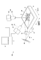
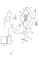
- FIG. 1 is an overall schematic diagram of a foreign matter inspection apparatus according to an embodiment of the present invention.
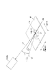
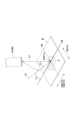
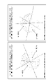
- FIG. It is a schematic diagram which shows the optical arrangement of the 1st photon detection part which concerns on the same embodiment. It is a schematic diagram which shows the optical arrangement of the 2nd photon detection part which concerns on the same embodiment. It is a simulation result of the diffracted light detected by each photon detection part of the same embodiment. It is a figure which shows typically the structure of the photon detection part of deformation
- a foreign matter inspection apparatus 100 of the present embodiment is for inspecting foreign matter on a substrate W on which a pattern such as a reticle is formed. As shown in FIG. A light irradiation unit 2 that irradiates with the substrate W, a first light detection unit 3A and a second light detection unit 3B that detect light reflected by the substrate W, and a first light detection unit 3A and a second light detection unit. A foreign object detector 4 for detecting a foreign object based on the output signal of 3B is provided.
- the foreign matter inspection apparatus 100 also includes a moving stage 5 that moves the substrate W to be inspected in a predetermined direction (here, the Y-axis direction).
- the light irradiation unit 2 irradiates the substrate W placed or held on the moving stage 5 with the laser beam LB while scanning it. It has a scanning mirror 22 such as a galvanomirror for scanning in the X-axis direction) and a scanning lens 23 such as an f ⁇ lens.
- the light irradiation unit 2 emits the laser light LB from the laser light source 21 obliquely above the substrate W at a predetermined angle (10 to 80 degrees with respect to the surface of the substrate W, and 30 degrees with respect to the surface of the substrate W in this embodiment). degree), and is configured to irradiate while linearly reciprocating scanning in the X direction.
- a laser tube such as a HeNe laser is used as the laser light source 21 .
- the first photodetector 3A and the second photodetector 3B detect reflected and scattered light from the surface of the substrate W, and are arranged obliquely above the substrate surface by a holding member (not shown). It consists of a condenser lens, a fixed slit plate (none of which is shown) having a slit for limiting incident light with respect to reflected scattered light, and a photodetector 31 (for example, a photomultiplier tube). Also, the first photodetector 3A and the second photodetector 3B are provided with a signal processor 32 for processing the light intensity signal of the photodetector 31.
- the first photodetector 3A and the second photodetector 3B are arranged such that the light-receiving elevation angle ⁇ with respect to the surface of the substrate W and the light-receiving horizontal angle ⁇ with respect to the scanning direction of the laser beam LB are different from each other.
- the elevation angle of light reception of the first photodetector 3A is represented as ⁇ 1
- the horizontal angle of light reception is represented as ⁇ 1
- the elevation angle of light reception of the second photodetector 3B is represented as ⁇ 2
- the horizontal angle of light reception is represented as ⁇ 2.
- the light-receiving elevation angle ⁇ is the angle between the substrate surface and the line L1 connecting the center of the light-receiving surface of the photodetector 31 and the scanning center of the laser beam LB on the surface of the substrate W.
- the horizontal light receiving angle ⁇ is the angle between the line L2 when the line L1 is projected onto the surface of the substrate and the scanning direction (X-axis direction).
- the first photodetector 3A of the present embodiment detects light diffracted from a pattern having a predetermined angle (20 to 40 degrees) with the scanning direction (X-axis direction). (also called diffracted light, etc.). Specifically, in the first photodetector 3A, the elevation angle ⁇ 1 of received light is 55 degrees and the horizontal angle ⁇ 1 of received light is -25 degrees.
- FIG. 4A shows a simulation of diffracted light at 20° and 40° received by the first photodetector 3A in this arrangement. Note that the center of intersection of the axes in FIG. 2 is the position detected by the photodetector 31 . At this time, it can be seen that the 20-degree diffracted light and the 40-degree diffracted light largely overlap the position to be detected, and the first photodetector 3A detects the 20 to 40-degree diffracted light.
- the second photodetector 3B detects diffracted light from a pattern with an angle other than a predetermined angle (for example, 50 to 60 degrees other than 20 to 40 degrees) with the scanning direction (X-axis direction). are placed. That is, the second photodetector 3B is located at a position where it does not receive diffracted light at a predetermined angle (20 to 40°) with the scanning direction (X-axis direction), or even if it receives the diffracted light, it is detected at a predetermined detection point, which will be described later. It is arranged at a position where the amount of light is less than the threshold.
- a predetermined angle for example, 50 to 60 degrees other than 20 to 40 degrees
- the light reception elevation angle ⁇ 2 is 35 degrees
- the light reception horizontal angle ⁇ 2 is 20 degrees
- FIG. 4B shows a simulation of diffracted light at 20° and 40° received by the second photodetector 3B in this arrangement.
- the 20-degree diffracted light and the 40-degree diffracted light do not cover the position detected by the second photodetector 3B, and the second photodetector 3B does not detect the 20 to 40-degree diffracted light.
- the 20-degree diffracted light and the 40-degree diffracted light do not cover the position detected by the second photodetector 3B, and the second photodetector 3B does not detect the 20 to 40-degree diffracted light.
- the light-receiving elevation angles ⁇ 1 and ⁇ 2 and the light-receiving horizontal angles ⁇ 1 and ⁇ 2 of the first photodetector 3A and the second photodetector 3B, respectively, are the incident angle of the laser beam LB to the substrate W, the swing angle of the laser beam LB, the pattern and the scanning direction (X-axis direction), and the angle between the normal to an arbitrary point on the edge of the pattern and the substrate surface.
- the foreign matter detector 4 detects foreign matter based on the output signals of the first photodetector 3A and the second photodetector 3B. Specifically, the foreign matter detector 4 determines that there is a foreign matter only when each of the output signals from the first photodetector 3A and the second photodetector 3B is equal to or greater than a predetermined detection threshold. On the other hand, the foreign matter detector 4 determines that the light is diffracted from the pattern when either of the output signals from the first photodetector 3A and the second photodetector 3B is less than a predetermined detection threshold.
- the predetermined detection threshold is set when each photodetector detects scattered light from a foreign object, when the first photodetector 3A detects 20 to 40° diffracted light, and when the second photodetector The value is set so that it can be determined when the portion 3B detects diffracted light at angles other than 20° to 40°.
- the predetermined detection threshold may be the same or different between the first photodetector 3A and the second photodetector 3B.
- the obtained foreign matter information (for example, location information and size information of the foreign matter) can be displayed on the display 6 of the foreign matter inspection device or the external device.
- the first photodetector 3A and the second photodetector 3B are arranged so that the elevation angle and the horizontal angle of light reception are different from each other.
- the first photodetector 3A detects diffracted light from a pattern with a predetermined angle to the scanning direction
- the second photodetector 3B detects diffracted light from a pattern other than the predetermined angle.
- Based on the output signal of the second photodetector 3A and the output signal of the second photodetector 3B it is possible to determine whether the light is scattered light from a foreign object or a pattern.
- erroneous detection due to diffracted light from a pattern forming a specific angle (for example, 20 to 40 degrees) with the scanning direction of the laser beam LB can be reduced.
- each of the first photodetector 3A and the second photodetector 3B has a plurality of (here, two) photodetectors 311 and 312 paired with each other. good too.
- the two photodetectors 311 and 312 of the first photodetection unit 3A are arranged in a pattern having a predetermined angle (20 to 40 degrees) with the scanning direction (X-axis direction), as in the above embodiment.
- the two photodetectors 311 and 312 of the second photodetection unit 3B have an angle other than a predetermined angle (for example, an angle other than 20 to 40 degrees) with the scanning direction (X-axis direction), as in the above embodiment. 50-60 degrees) to detect diffracted light from the pattern.
- the two detectors 311 and 312 of each of the photodetectors 3A and 3B are arranged symmetrically with respect to the Y-axis direction (direction perpendicular to the scanning direction).
- each of the two photodetectors paired with each other detects light from different positions in the linearly scanned laser light LB.
- one photodetector 311 detects light from one side (one half in the X-axis direction) from the scanning center
- the other photodetector 312 detects light from the other side from the scanning center. It detects light from (the other half in the X-axis direction).
- the detection areas of the two photodetectors 311 and 312 may partially overlap.
- a polarizing plate 7 may be provided in front of each of the first photodetector 3A and the second photodetector 3B.
- the rotation angle (polarization direction) of the polarizing plate 7 is set so that the difference between the scattered light intensity from the foreign matter and the scattered light intensity from the pattern is maximized.
- the compound eye configuration using the first photodetector 3A and the second photodetector 3B can discriminate strong diffracted light from the pattern (light of intensity that cannot be removed by the polarizer), and the polarizer 7 can detect the surrounding light. Disturbance light from can be blocked.
- erroneous detection due to diffracted light from a pattern forming a specific angle (for example, 20 to 40 degrees) with respect to the scanning direction of the laser beam can be reduced.
Landscapes
- Physics & Mathematics (AREA)
- General Physics & Mathematics (AREA)
- Health & Medical Sciences (AREA)
- Life Sciences & Earth Sciences (AREA)
- Chemical & Material Sciences (AREA)
- Analytical Chemistry (AREA)
- Biochemistry (AREA)
- General Health & Medical Sciences (AREA)
- Immunology (AREA)
- Pathology (AREA)
- Investigating Materials By The Use Of Optical Means Adapted For Particular Applications (AREA)
Abstract
Priority Applications (5)
| Application Number | Priority Date | Filing Date | Title |
|---|---|---|---|
| DE112022001630.2T DE112022001630T5 (de) | 2021-03-22 | 2022-02-07 | Teilchenuntersuchungsvorrichtung und teilchenuntersuchungsverfahren |
| KR1020237031084A KR20230159406A (ko) | 2021-03-22 | 2022-02-07 | 이물 검사 장치 및 이물 검사 방법 |
| JP2023508748A JPWO2022201910A1 (fr) | 2021-03-22 | 2022-02-07 | |
| US18/282,621 US20240159686A1 (en) | 2021-03-22 | 2022-02-07 | Particle inspection device and particle inspection method |
| CN202280022327.1A CN116997791A (zh) | 2021-03-22 | 2022-02-07 | 异物检查装置以及异物检查方法 |
Applications Claiming Priority (2)
| Application Number | Priority Date | Filing Date | Title |
|---|---|---|---|
| JP2021-047589 | 2021-03-22 | ||
| JP2021047589 | 2021-03-22 |
Publications (1)
| Publication Number | Publication Date |
|---|---|
| WO2022201910A1 true WO2022201910A1 (fr) | 2022-09-29 |
Family
ID=83395480
Family Applications (1)
| Application Number | Title | Priority Date | Filing Date |
|---|---|---|---|
| PCT/JP2022/004593 Ceased WO2022201910A1 (fr) | 2021-03-22 | 2022-02-07 | Dispositif d'inspection de corps étrangers et procédé d'inspection de corps étrangers |
Country Status (7)
| Country | Link |
|---|---|
| US (1) | US20240159686A1 (fr) |
| JP (1) | JPWO2022201910A1 (fr) |
| KR (1) | KR20230159406A (fr) |
| CN (1) | CN116997791A (fr) |
| DE (1) | DE112022001630T5 (fr) |
| TW (1) | TW202238111A (fr) |
| WO (1) | WO2022201910A1 (fr) |
Citations (4)
| Publication number | Priority date | Publication date | Assignee | Title |
|---|---|---|---|---|
| JPH0694633A (ja) * | 1992-09-09 | 1994-04-08 | Nikon Corp | 欠陥検査装置 |
| JP2002519694A (ja) * | 1998-07-07 | 2002-07-02 | アプライド マテリアルズ インコーポレイテッド | パターン化されたウエハ上の欠陥を検出するためのピクセルに基づいた方法及び装置 |
| JP2010002406A (ja) * | 2008-05-23 | 2010-01-07 | Hitachi High-Technologies Corp | 基板表面の検査方法及び検査装置 |
| WO2011105016A1 (fr) * | 2010-02-26 | 2011-09-01 | 株式会社日立ハイテクノロジーズ | Dispositif et procédé pour la détection de défauts |
Family Cites Families (8)
| Publication number | Priority date | Publication date | Assignee | Title |
|---|---|---|---|---|
| JPH0769272B2 (ja) | 1987-05-18 | 1995-07-26 | 株式会社ニコン | 異物検査装置 |
| US5798831A (en) * | 1991-12-19 | 1998-08-25 | Nikon Corporation | Defect inspecting apparatus and defect inspecting method |
| DE4403714C2 (de) | 1993-02-16 | 1996-12-05 | Kvaerner Ships Equipment Gmbh | Dichtungsanordnung für Schiffslukendeckel |
| WO2002082064A1 (fr) * | 2001-04-06 | 2002-10-17 | Kla-Tencor Corporation | Systeme de detection de defauts ameliore |
| US6538730B2 (en) * | 2001-04-06 | 2003-03-25 | Kla-Tencor Technologies Corporation | Defect detection system |
| JP2016057180A (ja) * | 2014-09-10 | 2016-04-21 | 東レエンジニアリング株式会社 | 基板検査装置 |
| JP6508082B2 (ja) * | 2016-02-12 | 2019-05-08 | 株式会社Sumco | エピタキシャルウェーハの評価方法 |
| CN111727369B (zh) * | 2018-02-28 | 2022-12-20 | 株式会社日立高新技术 | 检查装置及其检查方法 |
-
2022
- 2022-02-07 US US18/282,621 patent/US20240159686A1/en active Pending
- 2022-02-07 CN CN202280022327.1A patent/CN116997791A/zh active Pending
- 2022-02-07 WO PCT/JP2022/004593 patent/WO2022201910A1/fr not_active Ceased
- 2022-02-07 KR KR1020237031084A patent/KR20230159406A/ko active Pending
- 2022-02-07 JP JP2023508748A patent/JPWO2022201910A1/ja active Pending
- 2022-02-07 DE DE112022001630.2T patent/DE112022001630T5/de active Pending
- 2022-03-15 TW TW111109305A patent/TW202238111A/zh unknown
Patent Citations (4)
| Publication number | Priority date | Publication date | Assignee | Title |
|---|---|---|---|---|
| JPH0694633A (ja) * | 1992-09-09 | 1994-04-08 | Nikon Corp | 欠陥検査装置 |
| JP2002519694A (ja) * | 1998-07-07 | 2002-07-02 | アプライド マテリアルズ インコーポレイテッド | パターン化されたウエハ上の欠陥を検出するためのピクセルに基づいた方法及び装置 |
| JP2010002406A (ja) * | 2008-05-23 | 2010-01-07 | Hitachi High-Technologies Corp | 基板表面の検査方法及び検査装置 |
| WO2011105016A1 (fr) * | 2010-02-26 | 2011-09-01 | 株式会社日立ハイテクノロジーズ | Dispositif et procédé pour la détection de défauts |
Also Published As
| Publication number | Publication date |
|---|---|
| KR20230159406A (ko) | 2023-11-21 |
| DE112022001630T5 (de) | 2024-01-04 |
| JPWO2022201910A1 (fr) | 2022-09-29 |
| CN116997791A (zh) | 2023-11-03 |
| TW202238111A (zh) | 2022-10-01 |
| US20240159686A1 (en) | 2024-05-16 |
Similar Documents
| Publication | Publication Date | Title |
|---|---|---|
| US7436507B2 (en) | Method and apparatus for inspecting a pattern | |
| JPH0915163A (ja) | 異物検査方法及び装置 | |
| JP5268061B2 (ja) | 基板検査装置 | |
| JP5219487B2 (ja) | 欠陥検査装置及び欠陥検査プログラム | |
| JPH05100413A (ja) | 異物検査装置 | |
| US7433053B2 (en) | Laser inspection using diffractive elements for enhancement and suppression of surface features | |
| JPS6365904B2 (fr) | ||
| JP3185878B2 (ja) | 光学的検査装置 | |
| JP6476580B2 (ja) | 平板基板の表面状態検査装置及びそれを用いた平板基板の表面状態検査方法 | |
| WO2022201910A1 (fr) | Dispositif d'inspection de corps étrangers et procédé d'inspection de corps étrangers | |
| JPH07270326A (ja) | 異物検査装置 | |
| JP3280742B2 (ja) | ガラス基板用欠陥検査装置 | |
| JP2503919B2 (ja) | 異物検査装置 | |
| JP3168480B2 (ja) | 異物検査方法、および異物検査装置 | |
| JP2970235B2 (ja) | 表面状態検査装置 | |
| JPH04277643A (ja) | 透明基板の光学的検査装置 | |
| JPH07119700B2 (ja) | 異物検出装置 | |
| JP2006313107A (ja) | 検査装置及び検査方法並びにそれを用いたパターン基板の製造方法 | |
| JPH0216438A (ja) | 異物検査装置及びその方法 | |
| JP2026058835A (ja) | 異物検査装置、及び異物検査方法 | |
| JPH07134104A (ja) | 異物検査装置 | |
| JPH0545303A (ja) | 欠陥検査装置 | |
| JP2006023202A (ja) | 偏光解析装置 | |
| JPH02186248A (ja) | 表面状態検査装置 | |
| JPS60154635A (ja) | パタ−ン欠陥検査装置 |
Legal Events
| Date | Code | Title | Description |
|---|---|---|---|
| 121 | Ep: the epo has been informed by wipo that ep was designated in this application |
Ref document number: 22774711 Country of ref document: EP Kind code of ref document: A1 |
|
| ENP | Entry into the national phase |
Ref document number: 2023508748 Country of ref document: JP Kind code of ref document: A |
|
| WWE | Wipo information: entry into national phase |
Ref document number: 18282621 Country of ref document: US Ref document number: 202280022327.1 Country of ref document: CN |
|
| WWE | Wipo information: entry into national phase |
Ref document number: 112022001630 Country of ref document: DE |
|
| 122 | Ep: pct application non-entry in european phase |
Ref document number: 22774711 Country of ref document: EP Kind code of ref document: A1 |