WO2022201954A1 - 減速機 - Google Patents
減速機 Download PDFInfo
- Publication number
- WO2022201954A1 WO2022201954A1 PCT/JP2022/005470 JP2022005470W WO2022201954A1 WO 2022201954 A1 WO2022201954 A1 WO 2022201954A1 JP 2022005470 W JP2022005470 W JP 2022005470W WO 2022201954 A1 WO2022201954 A1 WO 2022201954A1
- Authority
- WO
- WIPO (PCT)
- Prior art keywords
- notch
- locking member
- ring nut
- housing
- press
- Prior art date
- Legal status (The legal status is an assumption and is not a legal conclusion. Google has not performed a legal analysis and makes no representation as to the accuracy of the status listed.)
- Ceased
Links
Images



Classifications
-
- F—MECHANICAL ENGINEERING; LIGHTING; HEATING; WEAPONS; BLASTING
- F16—ENGINEERING ELEMENTS AND UNITS; GENERAL MEASURES FOR PRODUCING AND MAINTAINING EFFECTIVE FUNCTIONING OF MACHINES OR INSTALLATIONS; THERMAL INSULATION IN GENERAL
- F16C—SHAFTS; FLEXIBLE SHAFTS; ELEMENTS OR CRANKSHAFT MECHANISMS; ROTARY BODIES OTHER THAN GEARING ELEMENTS; BEARINGS
- F16C35/00—Rigid support of bearing units; Housings, e.g. caps, covers
- F16C35/04—Rigid support of bearing units; Housings, e.g. caps, covers in the case of ball or roller bearings
- F16C35/06—Mounting or dismounting of ball or roller bearings; Fixing them onto shaft or in housing
- F16C35/07—Fixing them on the shaft or housing with interposition of an element
- F16C35/077—Fixing them on the shaft or housing with interposition of an element between housing and outer race ring
-
- F—MECHANICAL ENGINEERING; LIGHTING; HEATING; WEAPONS; BLASTING
- F16—ENGINEERING ELEMENTS AND UNITS; GENERAL MEASURES FOR PRODUCING AND MAINTAINING EFFECTIVE FUNCTIONING OF MACHINES OR INSTALLATIONS; THERMAL INSULATION IN GENERAL
- F16B—DEVICES FOR FASTENING OR SECURING CONSTRUCTIONAL ELEMENTS OR MACHINE PARTS TOGETHER, e.g. NAILS, BOLTS, CIRCLIPS, CLAMPS, CLIPS OR WEDGES; JOINTS OR JOINTING
- F16B39/00—Locking of screws, bolts or nuts
- F16B39/02—Locking of screws, bolts or nuts in which the locking takes place after screwing down
- F16B39/04—Locking of screws, bolts or nuts in which the locking takes place after screwing down with a member penetrating the screw-threaded surface of at least one part, e.g. a pin, a wedge, cotter-pin, screw
-
- B—PERFORMING OPERATIONS; TRANSPORTING
- B60—VEHICLES IN GENERAL
- B60K—ARRANGEMENT OR MOUNTING OF PROPULSION UNITS OR OF TRANSMISSIONS IN VEHICLES; ARRANGEMENT OR MOUNTING OF PLURAL DIVERSE PRIME-MOVERS IN VEHICLES; AUXILIARY DRIVES FOR VEHICLES; INSTRUMENTATION OR DASHBOARDS FOR VEHICLES; ARRANGEMENTS IN CONNECTION WITH COOLING, AIR INTAKE, GAS EXHAUST OR FUEL SUPPLY OF PROPULSION UNITS IN VEHICLES
- B60K17/00—Arrangement or mounting of transmissions in vehicles
- B60K17/04—Arrangement or mounting of transmissions in vehicles characterised by arrangement, location or kind of gearing
- B60K17/043—Transmission unit disposed in on near the vehicle wheel, or between the differential gear unit and the wheel
- B60K17/046—Transmission unit disposed in on near the vehicle wheel, or between the differential gear unit and the wheel with planetary gearing having orbital motion
-
- F—MECHANICAL ENGINEERING; LIGHTING; HEATING; WEAPONS; BLASTING
- F16—ENGINEERING ELEMENTS AND UNITS; GENERAL MEASURES FOR PRODUCING AND MAINTAINING EFFECTIVE FUNCTIONING OF MACHINES OR INSTALLATIONS; THERMAL INSULATION IN GENERAL
- F16B—DEVICES FOR FASTENING OR SECURING CONSTRUCTIONAL ELEMENTS OR MACHINE PARTS TOGETHER, e.g. NAILS, BOLTS, CIRCLIPS, CLAMPS, CLIPS OR WEDGES; JOINTS OR JOINTING
- F16B39/00—Locking of screws, bolts or nuts
- F16B39/02—Locking of screws, bolts or nuts in which the locking takes place after screwing down
- F16B39/10—Locking of screws, bolts or nuts in which the locking takes place after screwing down by a plate, spring, wire or ring immovable with regard to the bolt or object and mainly perpendicular to the axis of the bolt
-
- F—MECHANICAL ENGINEERING; LIGHTING; HEATING; WEAPONS; BLASTING
- F16—ENGINEERING ELEMENTS AND UNITS; GENERAL MEASURES FOR PRODUCING AND MAINTAINING EFFECTIVE FUNCTIONING OF MACHINES OR INSTALLATIONS; THERMAL INSULATION IN GENERAL
- F16C—SHAFTS; FLEXIBLE SHAFTS; ELEMENTS OR CRANKSHAFT MECHANISMS; ROTARY BODIES OTHER THAN GEARING ELEMENTS; BEARINGS
- F16C35/00—Rigid support of bearing units; Housings, e.g. caps, covers
- F16C35/04—Rigid support of bearing units; Housings, e.g. caps, covers in the case of ball or roller bearings
- F16C35/06—Mounting or dismounting of ball or roller bearings; Fixing them onto shaft or in housing
- F16C35/07—Fixing them on the shaft or housing with interposition of an element
- F16C35/073—Fixing them on the shaft or housing with interposition of an element between shaft and inner race ring
-
- F—MECHANICAL ENGINEERING; LIGHTING; HEATING; WEAPONS; BLASTING
- F16—ENGINEERING ELEMENTS AND UNITS; GENERAL MEASURES FOR PRODUCING AND MAINTAINING EFFECTIVE FUNCTIONING OF MACHINES OR INSTALLATIONS; THERMAL INSULATION IN GENERAL
- F16H—GEARING
- F16H57/00—General details of gearing
- F16H57/02—Gearboxes; Mounting gearing therein
- F16H57/021—Shaft support structures, e.g. partition walls, bearing eyes, casing walls or covers with bearings
- F16H57/022—Adjustment of gear shafts or bearings
-
- F—MECHANICAL ENGINEERING; LIGHTING; HEATING; WEAPONS; BLASTING
- F16—ENGINEERING ELEMENTS AND UNITS; GENERAL MEASURES FOR PRODUCING AND MAINTAINING EFFECTIVE FUNCTIONING OF MACHINES OR INSTALLATIONS; THERMAL INSULATION IN GENERAL
- F16H—GEARING
- F16H57/00—General details of gearing
- F16H57/02—Gearboxes; Mounting gearing therein
- F16H57/023—Mounting or installation of gears or shafts in the gearboxes, e.g. methods or means for assembly
-
- B—PERFORMING OPERATIONS; TRANSPORTING
- B60—VEHICLES IN GENERAL
- B60K—ARRANGEMENT OR MOUNTING OF PROPULSION UNITS OR OF TRANSMISSIONS IN VEHICLES; ARRANGEMENT OR MOUNTING OF PLURAL DIVERSE PRIME-MOVERS IN VEHICLES; AUXILIARY DRIVES FOR VEHICLES; INSTRUMENTATION OR DASHBOARDS FOR VEHICLES; ARRANGEMENTS IN CONNECTION WITH COOLING, AIR INTAKE, GAS EXHAUST OR FUEL SUPPLY OF PROPULSION UNITS IN VEHICLES
- B60K7/00—Disposition of motor in, or adjacent to, traction wheel
- B60K2007/0038—Disposition of motor in, or adjacent to, traction wheel the motor moving together with the wheel axle
-
- B—PERFORMING OPERATIONS; TRANSPORTING
- B60—VEHICLES IN GENERAL
- B60K—ARRANGEMENT OR MOUNTING OF PROPULSION UNITS OR OF TRANSMISSIONS IN VEHICLES; ARRANGEMENT OR MOUNTING OF PLURAL DIVERSE PRIME-MOVERS IN VEHICLES; AUXILIARY DRIVES FOR VEHICLES; INSTRUMENTATION OR DASHBOARDS FOR VEHICLES; ARRANGEMENTS IN CONNECTION WITH COOLING, AIR INTAKE, GAS EXHAUST OR FUEL SUPPLY OF PROPULSION UNITS IN VEHICLES
- B60K7/00—Disposition of motor in, or adjacent to, traction wheel
- B60K2007/0092—Disposition of motor in, or adjacent to, traction wheel the motor axle being coaxial to the wheel axle
-
- B—PERFORMING OPERATIONS; TRANSPORTING
- B60—VEHICLES IN GENERAL
- B60K—ARRANGEMENT OR MOUNTING OF PROPULSION UNITS OR OF TRANSMISSIONS IN VEHICLES; ARRANGEMENT OR MOUNTING OF PLURAL DIVERSE PRIME-MOVERS IN VEHICLES; AUXILIARY DRIVES FOR VEHICLES; INSTRUMENTATION OR DASHBOARDS FOR VEHICLES; ARRANGEMENTS IN CONNECTION WITH COOLING, AIR INTAKE, GAS EXHAUST OR FUEL SUPPLY OF PROPULSION UNITS IN VEHICLES
- B60K7/00—Disposition of motor in, or adjacent to, traction wheel
- B60K7/0015—Disposition of motor in, or adjacent to, traction wheel the motor being hydraulic
-
- B—PERFORMING OPERATIONS; TRANSPORTING
- B60—VEHICLES IN GENERAL
- B60Y—INDEXING SCHEME RELATING TO ASPECTS CROSS-CUTTING VEHICLE TECHNOLOGY
- B60Y2200/00—Type of vehicle
- B60Y2200/40—Special vehicles
- B60Y2200/41—Construction vehicles, e.g. graders, excavators
- B60Y2200/412—Excavators
-
- F—MECHANICAL ENGINEERING; LIGHTING; HEATING; WEAPONS; BLASTING
- F16—ENGINEERING ELEMENTS AND UNITS; GENERAL MEASURES FOR PRODUCING AND MAINTAINING EFFECTIVE FUNCTIONING OF MACHINES OR INSTALLATIONS; THERMAL INSULATION IN GENERAL
- F16C—SHAFTS; FLEXIBLE SHAFTS; ELEMENTS OR CRANKSHAFT MECHANISMS; ROTARY BODIES OTHER THAN GEARING ELEMENTS; BEARINGS
- F16C19/00—Bearings with rolling contact, for exclusively rotary movement
- F16C19/02—Bearings with rolling contact, for exclusively rotary movement with bearing balls essentially of the same size in one or more circular rows
- F16C19/14—Bearings with rolling contact, for exclusively rotary movement with bearing balls essentially of the same size in one or more circular rows for both radial and axial load
- F16C19/18—Bearings with rolling contact, for exclusively rotary movement with bearing balls essentially of the same size in one or more circular rows for both radial and axial load with two or more rows of balls
- F16C19/181—Bearings with rolling contact, for exclusively rotary movement with bearing balls essentially of the same size in one or more circular rows for both radial and axial load with two or more rows of balls with angular contact
- F16C19/183—Bearings with rolling contact, for exclusively rotary movement with bearing balls essentially of the same size in one or more circular rows for both radial and axial load with two or more rows of balls with angular contact with two rows at opposite angles
- F16C19/184—Bearings with rolling contact, for exclusively rotary movement with bearing balls essentially of the same size in one or more circular rows for both radial and axial load with two or more rows of balls with angular contact with two rows at opposite angles in O-arrangement
-
- F—MECHANICAL ENGINEERING; LIGHTING; HEATING; WEAPONS; BLASTING
- F16—ENGINEERING ELEMENTS AND UNITS; GENERAL MEASURES FOR PRODUCING AND MAINTAINING EFFECTIVE FUNCTIONING OF MACHINES OR INSTALLATIONS; THERMAL INSULATION IN GENERAL
- F16C—SHAFTS; FLEXIBLE SHAFTS; ELEMENTS OR CRANKSHAFT MECHANISMS; ROTARY BODIES OTHER THAN GEARING ELEMENTS; BEARINGS
- F16C2226/00—Joining parts; Fastening; Assembling or mounting parts
- F16C2226/50—Positive connections
- F16C2226/60—Positive connections with threaded parts, e.g. bolt and nut connections
-
- F—MECHANICAL ENGINEERING; LIGHTING; HEATING; WEAPONS; BLASTING
- F16—ENGINEERING ELEMENTS AND UNITS; GENERAL MEASURES FOR PRODUCING AND MAINTAINING EFFECTIVE FUNCTIONING OF MACHINES OR INSTALLATIONS; THERMAL INSULATION IN GENERAL
- F16C—SHAFTS; FLEXIBLE SHAFTS; ELEMENTS OR CRANKSHAFT MECHANISMS; ROTARY BODIES OTHER THAN GEARING ELEMENTS; BEARINGS
- F16C2226/00—Joining parts; Fastening; Assembling or mounting parts
- F16C2226/50—Positive connections
- F16C2226/62—Positive connections with pins, bolts or dowels
-
- F—MECHANICAL ENGINEERING; LIGHTING; HEATING; WEAPONS; BLASTING
- F16—ENGINEERING ELEMENTS AND UNITS; GENERAL MEASURES FOR PRODUCING AND MAINTAINING EFFECTIVE FUNCTIONING OF MACHINES OR INSTALLATIONS; THERMAL INSULATION IN GENERAL
- F16C—SHAFTS; FLEXIBLE SHAFTS; ELEMENTS OR CRANKSHAFT MECHANISMS; ROTARY BODIES OTHER THAN GEARING ELEMENTS; BEARINGS
- F16C2229/00—Setting preload
-
- F—MECHANICAL ENGINEERING; LIGHTING; HEATING; WEAPONS; BLASTING
- F16—ENGINEERING ELEMENTS AND UNITS; GENERAL MEASURES FOR PRODUCING AND MAINTAINING EFFECTIVE FUNCTIONING OF MACHINES OR INSTALLATIONS; THERMAL INSULATION IN GENERAL
- F16C—SHAFTS; FLEXIBLE SHAFTS; ELEMENTS OR CRANKSHAFT MECHANISMS; ROTARY BODIES OTHER THAN GEARING ELEMENTS; BEARINGS
- F16C2361/00—Apparatus or articles in engineering in general
- F16C2361/61—Toothed gear systems, e.g. support of pinion shafts
-
- F—MECHANICAL ENGINEERING; LIGHTING; HEATING; WEAPONS; BLASTING
- F16—ENGINEERING ELEMENTS AND UNITS; GENERAL MEASURES FOR PRODUCING AND MAINTAINING EFFECTIVE FUNCTIONING OF MACHINES OR INSTALLATIONS; THERMAL INSULATION IN GENERAL
- F16H—GEARING
- F16H1/00—Toothed gearings for conveying rotary motion
- F16H1/28—Toothed gearings for conveying rotary motion with gears having orbital motion
- F16H1/46—Systems consisting of a plurality of gear trains each with orbital gears, i.e. systems having three or more central gears
-
- F—MECHANICAL ENGINEERING; LIGHTING; HEATING; WEAPONS; BLASTING
- F16—ENGINEERING ELEMENTS AND UNITS; GENERAL MEASURES FOR PRODUCING AND MAINTAINING EFFECTIVE FUNCTIONING OF MACHINES OR INSTALLATIONS; THERMAL INSULATION IN GENERAL
- F16H—GEARING
- F16H57/00—General details of gearing
- F16H57/02—Gearboxes; Mounting gearing therein
- F16H57/021—Shaft support structures, e.g. partition walls, bearing eyes, casing walls or covers with bearings
- F16H57/022—Adjustment of gear shafts or bearings
- F16H2057/0221—Axial adjustment
Definitions
- the present invention relates to a speed reducer.
- JP2006-161753A discloses a hydraulic motor with a reduction gear, which is composed of a variable displacement swash plate type hydraulic motor and a reduction gear.
- the rotation of the hydraulic motor is reduced by the planetary gear reduction mechanism of the speed reducer and transmitted to the casing of the speed reducer to rotate the casing of the speed reducer with high torque.
- a bearing is provided between the outer peripheral surface of the casing of the hydraulic motor and the inner peripheral surface of the casing of the speed reducer, and the bearing rotatably supports the casing of the speed reducer with respect to the casing of the hydraulic motor.
- the bearing is retained by a nut screwed onto the male threaded portion of the casing of the hydraulic motor.
- the nut of the hydraulic motor with reduction gear described in JP2006-161753A receives force in the axial direction from the bearing. Therefore, it is conceivable that the nut may be loosened as the hydraulic motor with reduction gear is operated.
- the casing of the hydraulic motor is provided with an insertion hole that is partially open in the outer peripheral surface of the casing of the hydraulic motor and extends in the axial direction of the male screw portion of the casing of the hydraulic motor.
- the insertion hole is formed with a female thread portion that is screwed with the male thread portion of the plug by tapping or the like. Since part of the insertion hole opens to the outer peripheral surface of the casing of the hydraulic motor, part of the internal thread of the nut faces the insertion hole when the nut is screwed onto the casing of the hydraulic motor. Therefore, by screwing the plug into the insertion hole in this state, the male threaded portion of the plug bites into and engages with the female threaded portion of the nut. This prevents the nut from loosening.
- an insertion hole is provided in the casing of the hydraulic motor, and a female screw portion is formed in the insertion hole.
- burrs are generated in the opening when the female screw portion is formed in the insertion hole. Therefore, a step of removing the burr is also required.
- the locking mechanism for the nut as described above is time-consuming to process.
- An object of the present invention is to easily prevent the ring nut of a speed reducer from loosening.
- a speed reducer comprising: a stationary housing that accommodates a drive source and has a male threaded portion on an outer peripheral surface; a rotary housing that rotates by being transmitted with the output rotation of the drive source; and the rotary housing.
- a deceleration mechanism housed in a drive source for decelerating and transmitting the output rotation to the rotating housing; a bearing member attached to the fixed housing for rotatably supporting the rotating housing with respect to the fixed housing; A ring nut that is screwed onto the male threaded portion of the fixed housing to prevent the bearing member from coming off, and a locking member that prevents the ring nut from loosening.
- a notch opening in the outer peripheral surface of the housing and extending in the axial direction is provided, and the locking member is press-fitted between the notch and the ring nut to be fixed in the notch, and the ring nut. engages in the circumferential direction.
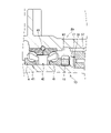
- FIG. 1 is a cross-sectional view of the speed reducer according to the present embodiment, showing a state before the locking member is attached.
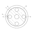
- FIG. 2 is a partial cross-sectional view showing enlarged II shown in FIG. 3 is a cross-sectional view of the fixed housing and the ring nut viewed from the III section shown in FIG. 1.
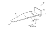
- FIG. FIG. 4 is a perspective view of the locking member.
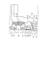
- FIG. 5 is an enlarged cross-sectional view showing a state after the locking member of the speed reducer according to the present embodiment has been attached, corresponding to FIG.
- FIG. 6 is an enlarged partial cross-sectional view showing VI shown in FIG. 3, showing a state after the locking member is attached.
- FIG. 7 is an enlarged cross-sectional view showing a state after attachment of the locking member of the modified example, corresponding to FIG.
- a speed reducer 100 according to an embodiment of the present invention will be described with reference to the drawings.
- a speed reducer that reduces the power of a hydraulic motor which is a drive source for traveling a crawler-type work machine such as a hydraulic excavator, and transmits the reduced power to a crawler belt will be described as an example.
- the speed reducer 100 includes a fixed housing 10 that houses a hydraulic motor 9 as a drive source, a rotary housing 20 that is rotatably provided with respect to the fixed housing 10, and a hydraulic motor that is housed in the rotary housing 20. a deceleration mechanism 30 for decelerating the output rotation of the shaft 31 of the motor 9 and transmitting it to the rotary housing 20 ;
- the rotation housing 20 is a cylindrical member, and rotates when the output rotation of the hydraulic motor 9 is transmitted through the speed reduction mechanism 30 .
- the fixed housing 10 and the rotating housing 20 are arranged inside the path along which the crawler belt circulates.
- the rotary housing 20 is formed with an annular rotary flange 29 protruding radially outward from the outer peripheral surface 22 .
- a sprocket (not shown) is fastened to the rotary flange 29 with bolts.
- a crawler belt meshes with the sprocket.
- the speed reducer 100 includes a bearing unit 40 as a bearing member provided between the outer circumference of the fixed housing 10 and the inner circumference of the rotary housing 20, and a ring nut 60 that prevents the bearing unit 40 from coming off.
- the bearing unit 40 includes a pair of bearings 41 that rotatably support the rotary housing 20 with respect to the fixed housing 10, a snap ring 49 that restricts axial relative movement between the bearings 41 and the rotary housing 20, and have The pair of bearings 41 have the same configuration and are arranged symmetrically.
- the bearing 41 is a single-row angular ball bearing in which a straight line connecting the contact points between the balls and the inner ring and the contact points between the balls and the outer ring forms a predetermined angle (contact angle) with respect to the radial direction.
- a pair of bearings 41 are attached to the outer peripheral surface of the stationary housing 10 .
- the stationary housing 10 has a stepped portion 16 and a male screw portion 17 on its outer peripheral surface.
- the ring nut 60 is screwed onto the male threaded portion 17 of the stationary housing 10 .
- a pair of bearings 41 are sandwiched between the stepped portion 16 of the stationary housing 10 and the ring nut 60 .
- the ring nut 60 receives force from the pair of bearings 41 in the axial direction. Therefore, in order to prevent the ring nut 60 from loosening due to the operation of the speed reducer 100, the loosening prevention member 70 prevents the ring nut 60 from loosening.
- the rotary housing 20 is rotatably supported via a pair of bearings 41 with respect to the fixed housing 10 fixed to the vehicle body 6 as an external member, and rotates around the rotation center axis O. do.
- the hydraulic motor 9 is housed inside the body portion 11 of the fixed housing 10 .
- the hydraulic motor 9 is, for example, a swash plate type piston motor. Since the hydraulic motor 9 can employ a known configuration, detailed description thereof will be omitted.
- the drive source may be other than the hydraulic motor, for example, the drive source may be an electric motor.
- a fixed flange 12 is formed on the fixed housing 10 so as to protrude from the outer peripheral surface of the body portion 11 .
- the fixed housing 10 is fixed to the vehicle body 6 by attaching the fixed flange 12 to the vehicle body 6 with bolts.
- the reduction mechanism 30 is a planetary gear reduction mechanism that reduces the output rotation of the shaft 31 of the hydraulic motor 9 and transmits it to the rotation housing 20, and has a gear portion 38.
- the gear portion 38 includes a sun gear 32 provided on the shaft 31 of the hydraulic motor 9, an inner gear 33 provided on the inner wall of the rotary housing 20, a plurality of planetary gears 34 meshing with both the sun gear 32 and the inner gear 33, and each planetary gear. , a second-stage sun gear 36 meshing with the planetary carrier 35, and a plurality of planetary gears 37 meshing with both the sun gear 36 and the inner gear 33.
- a washer 39 is provided on the planetary gear 37 . Note that the washer 39 may not be provided.
- a floating seal 50 is provided between the stationary housing 10 and the rotating housing 20 to seal the gap between the stationary housing 10 and the rotating housing 20 .
- the floating seal 50 seals the oil in the speed reducer 100 from leaking to the outside when the rotary housing 20 rotates, and also prevents foreign matter such as mud from entering the speed reducer from the outside.
- FIG. 3 is a cross-sectional view of the fixed housing 10 and the ring nut 60 seen from the III cross section shown in FIG. 1, showing the state before the locking member 70 is attached.
- FIG. 3 configurations other than the fixed housing 10 and the ring nut 60 are omitted.
- 4 is a perspective view of the locking member 70.
- FIG. FIG. 5 is an enlarged cross-sectional view showing a state after the locking member 70 is attached, corresponding to FIG.
- FIG. 6 is an enlarged partial cross-sectional view showing the VI portion shown in FIG. 3, showing a state after the locking member 70 is attached.
- the externally threaded portion 17 of the fixed housing 10 is provided with a notch 18 which opens in the outer peripheral surface of the fixed housing 10 with a predetermined width and extends in the axial direction.
- the notches 18 are formed in an arcuate cross-section along the radial direction of the male threaded portion 17 and are provided on the stationary housing 10 at two opposing positions with the shaft 31 of the hydraulic motor 9 interposed therebetween. Three or more notches 18 may be provided at equal intervals in the circumferential direction of the fixed housing 10 .
- the notch 18 is formed so that a part of the curved surface portion 71 of the locking member 70 protrudes beyond the outer peripheral surface of the fixed housing 10 from the notch 18 when the locking member 70 is press-fitted, as will be described later. be done.
- the speed reducer 100 includes a locking member 70 that locks the ring nut 60 from loosening.
- the locking member 70 is made of metal with high hardness.
- the locking member 70 is press-fitted between the inner peripheral surface of the notch 18 and the ring nut 60 to be fixed in the notch 18 and engaged with the ring nut 60 in the circumferential direction. As a result, the ring nut 60 is prevented from loosening.
- the locking member 70 is formed so as to extend in the press-fitting direction (arrow direction in FIG. 4) into the notch 18 .
- the locking member 70 has an arc-shaped curved surface portion 71 , a tip portion 72 that is first press-fitted into the notch 18 (in other words, an end on the front side in the press-fitting direction), and a tip portion 72 that is press-fitted into the notch 18 .
- the tapered portion 73 is press-fitted into the notch 18 , the length in the tangential direction connecting the two open ends of the notch 18 to the outer peripheral surface of the fixed housing 10 decreases toward the tip portion 72 .
- the tapered portion 73 is provided between the tip portion 72 and the curved surface portion 71 and is formed into a curved surface that is continuous with the curved surface portion 71 .
- the head portion 75 projects radially outward from the male threaded portion 17 from the end portion 74 in a state of being press-fitted into the notch 18 .
- the locking member 70 extends in the press-fitting direction into the notch 18 and is bent in the radial direction of the male threaded portion 17 in a state of being press-fitted into the notch 18 .
- the locking member 70 is configured such that the inner peripheral surface 71 a of the curved surface portion 71 extends radially outward of the male threaded portion 17 in a state where the ring nut 60 is screwed onto the male threaded portion 17 of the fixed housing 10 . It is press-fitted into the notch 18 from the tapered portion 73. Since the head 75 of the locking member 70 extends perpendicularly to the direction of press-fitting into the notch 18 , the locking member 70 can be easily notched by applying a load to the head 75 by driving the head 75 or the like. 18 can be press fit. A load is applied to the head portion 75 until the curved portion 71 is press-fitted into the notch 18 . In this manner, the curved surface portion 71 is press-fitted into the notch 18 with the inner peripheral surface 71 a facing radially outward of the male threaded portion 17 .
- the notch 18 is formed in a portion of the curved surface portion 71 of the locking member 70 (specifically, both ends of the curved surface portion 71 in the circumferential direction) when the locking member 70 is press-fitted. ) is formed so as to protrude radially outward from the notch 18 beyond the outer peripheral surface of the stationary housing 10 .
- the length L1 of the curved surface portion 71 of the locking member 70 in the radial direction of the male threaded portion 17 is equal to the depth L2 of the notch 18 in the radial direction of the male threaded portion 17.
- the locking member 70 when the locking member 70 is press-fitted into the notch 18 with the ring nut 60 screwed onto the male threaded portion 17 , the portion of the curved surface portion 71 protruding from the notch 18 bites into the female threaded portion of the ring nut 60 . , circumferentially engages the internal threads. Thereby, the locking member 70 is fixed in the notch 18 and prevents the ring nut 60 from loosening.
- Such a locking mechanism for the ring nut 60 is formed by providing the notch 18 in the male threaded portion 17 of the fixed housing 10 .
- the notch 18 is formed in the outer peripheral surface of the stationary housing 10 at the portion where the ring nut 60 is attached.
- the external threaded portion 17 is formed on the outer peripheral surface of the fixed housing 10 including the notch 18 .
- a male threaded portion is not formed on the inner peripheral surface of the notch 18 .
- a locking member having a male thread For example, consider locking the ring nut with a locking member having a male thread.
- an insertion hole that is partially open in the outer peripheral surface of the stationary housing and extends in the axial direction of the male threaded portion of the stationary housing is provided, and the male threaded portion of the plug is screwed into the insertion hole by tapping or the like.
- a female thread is provided.
- the locking member 70 is press-fitted into the notch 18 and fixed in the notch 18 . Therefore, the process of forming an internal thread for preventing the ring nut 60 from loosening is not required, and the process of removing burrs is also reduced. Therefore, it is possible to easily prevent the ring nut 60 from loosening with a small number of man-hours.
- the curved surface portion 71 of the locking member 70 is press-fitted into the notch 18 with the inner peripheral surface 71a facing radially outwardly of the male threaded portion 17, the curved surface portion 71 at both ends in the circumferential direction is formed into a ring. It engages the nut 60 . Specifically, two corners between the inner peripheral surface 71a of the curved surface portion 71 and both side surfaces 71b and 71c (see FIG. 6) of the curved surface portion 71 bite into the female screw portion of the ring nut 60 and are engaged. do. Therefore, it is possible to more reliably prevent the ring nut 60 from loosening.
- the locking member 70 has a tapered portion 73 whose length corresponding to the width direction of the notch 18 in a state of being press-fitted into the notch 18 decreases toward the tip portion 72 . Since it is press-fitted into the notch 18 from the portion 72 , the locking member 70 can be easily press-fitted into the notch 18 .
- the locking member 70 does not have to have the tapered portion 73 . Further, the locking member 70 does not need to have the head 75 as long as the load can be applied until the curved surface portion 71 is press-fitted into the notch 18 .
- the fixed housing 10 is provided with a gear portion 38 of the speed reduction mechanism 30 so as to intersect the extension of the notch 18 .
- the notch 18 and the gear portion 38 face each other in the axial direction of the male threaded portion 17 without any other member interposed therebetween.
- the distance between the gear portion 38 and the ring nut 60 in the axial direction of the male screw portion 17 is smaller than the length of the locking member 70 in the direction of press fitting into the notch 18 .
- the gear portion 38 (specifically, the gear portion 38 ) is removed before the anti-loosening member 70 falls off from the notch 18 . contact with the planetary gear 37 or a washer 39 provided on the planetary gear 37). This prevents the locking member 70 from coming off the notch 18 .
- the notch 18 is provided in the male threaded portion 17 of the fixed housing 10, and the curved surface portion 71 of the locking member 70 is press-fitted into the notch 18 to engage the ring nut 60 in the circumferential direction. 60 locks are applied. Since the anti-loosening member 70 is press-fitted into the notch 18 and fixed in the notch 18, the step of forming an internal thread portion for anti-loosening of the ring nut 60 is not required, and the step of removing burrs is also reduced. be. Therefore, it is possible to easily prevent the ring nut 60 from loosening with a small number of man-hours.
- the head 75 of the locking member 70 extends perpendicularly to the direction of press-fitting into the notch 18 . Therefore, by applying a load to the head portion 75 , the locking member 70 can be easily press-fitted into the notch 18 .
- the curved surface portion 71 is press-fitted into the notch 18 , and two circumferential ends of the curved surface portion 71 are engaged with the ring nut 60 . Therefore, the ring nut 60 can be prevented from loosening more reliably.
- the anti-loosening member 70 has a tapered portion 73 whose length corresponding to the width direction of the notch 18 in a state of being press-fitted into the notch 18 becomes smaller toward the tip portion 72 . is pressed in. Therefore, the locking member 70 can be easily press-fitted into the notch 18 .
- the reduction mechanism 30 has a gear portion 38 provided so as to intersect the extension of the notch 18 , and the distance between the gear portion 38 and the ring nut 60 in the axial direction of the male threaded portion 17 is the distance to the notch 18 . It is smaller than the length of the locking member 70 in the press fitting direction. As a result, even if the locking member 70 press-fitted into the notch 18 receives a force in the direction of coming off the notch 18, the locking member 70 comes into contact with the gear part 38 before coming off the notch 18. . Therefore, the locking member 70 is prevented from falling out of the notch 18 .
- the locking member 70 in the above embodiment has an arc-shaped curved surface portion 71 and a curved tapered portion 73 that is continuous with the curved surface portion 71 .
- the locking member 70 does not have the arc-shaped curved surface portion 71, but instead has a planar planar portion 171, and the tapered portion 73 is formed in a planar shape that is continuous with the planar portion 171. good too.
- the flat portion 171 of the locking member 70 bites into the female threaded portion of the ring nut 60 and engages with the female threaded portion in the circumferential direction.
- the notch 18 is formed in a triangular shape in a cross section along the radial direction of the male threaded portion 17 . Then, it is press-fitted into the notch 18 so that the inner peripheral surface of the notch 18 and the flat portion 171 of the locking member 70 are in contact with each other, and one of the corners of the flat portion 171 of the locking member 70 is the female thread of the ring nut 60. portion of the ring nut 60 and engages with the female threaded portion of the ring nut 60 in the circumferential direction.
- the speed reducer 100 includes a fixed housing 10 that accommodates a hydraulic motor 9 as a drive source and has a male threaded portion 17 on the outer peripheral surface, a rotary housing 20 that rotates when the output rotation of the hydraulic motor 9 is transmitted, and the rotary housing 20.
- a notch 18 that opens in the outer peripheral surface of the fixed housing 10 with a predetermined width and extends in the axial direction is provided. It is fixed and circumferentially engages the ring nut 60 .
- a notch 18 is provided in the male threaded portion 17 of the fixed housing 10, and the locking member 70 is press-fitted into the notch 18 to engage with the ring nut 60 in the circumferential direction, thereby locking the ring nut 60. be done. Since the anti-loosening member 70 is press-fitted into the notch 18 and fixed in the notch 18, the step of forming an internal thread portion for anti-loosening of the ring nut 60 is not required, and the step of removing burrs is also reduced. be. Therefore, it is possible to easily prevent the ring nut 60 from loosening with a small number of man-hours.
- the locking member 70 has an arc-shaped curved surface portion 71, and the curved surface portion 71 is press-fitted into the notch 18 with the inner peripheral surface 71a facing radially outward of the male thread portion 17. .
- the locking member 70 is press-fitted into the notch 18 and the two ends of the curved surface portion 71 are engaged with the ring nut 60 . Therefore, the ring nut 60 can be prevented from loosening more reliably.
- the locking member 70 has a tapered portion 73 whose length corresponding to the width direction of the notch 18 in a state of being press-fitted into the notch 18 decreases toward the distal end portion 72.
- the portion 73 is press-fitted into the notch 18 from the tip portion 72 .
- the tapered portion 73 makes it easier for the locking member 70 to be press-fitted into the notch 18 .
- the reduction mechanism 30 has the gear portion 38 provided so as to intersect the extension line of the notch 18, and the distance between the gear portion 38 and the ring nut 60 in the axial direction is equal to that of the notch. 18 is smaller than the length of the locking member 70 in the press-fit direction.
- the gear portion 38 of the speed reduction mechanism 30 prevents the locking member 70 from falling out of the notch 18 .
Landscapes
- Engineering & Computer Science (AREA)
- General Engineering & Computer Science (AREA)
- Mechanical Engineering (AREA)
- Chemical & Material Sciences (AREA)
- Combustion & Propulsion (AREA)
- Transportation (AREA)
- General Details Of Gearings (AREA)
- Mounting Of Bearings Or Others (AREA)
Abstract
Description
上記実施形態における緩み止め部材70は、円弧状の曲面部71と、曲面部71と連続した曲面状のテーパ部73と、を有する。これに限らず、緩み止め部材70は、円弧状の曲面部71を有さず、代わりに平面状の平面部171を有し、テーパ部73が平面部171と連続した平面状に形成されてもよい。この場合は、図7に示すように、緩み止め部材70の平面部171がリングナット60の雌ねじ部に食い込み、雌ねじ部と周方向に係合すればよい。切欠き18は、雄ねじ部17の径方向に沿った断面において三角形状に形成される。そして、切欠き18の内周面と緩み止め部材70の平面部171とが接触するように切欠き18に圧入され、緩み止め部材70の平面部171の角部の一つがリングナット60の雌ねじ部に食い込み、リングナット60の雌ねじ部と周方向に係合する。
Claims (4)
- 減速機であって、
駆動源を収容し外周面に雄ねじ部を有する固定ハウジングと、
前記駆動源の出力回転が伝達されて回転する回転ハウジングと、
前記回転ハウジングに収容され前記駆動源の出力回転を減速して前記回転ハウジングに伝達する減速機構と、
前記固定ハウジングに取り付けられ、前記固定ハウジングに対して前記回転ハウジングを回転自在に支持する軸受部材と、
前記固定ハウジングの前記雄ねじ部と螺合し前記軸受部材の抜け止めをするリングナットと、
前記リングナットの緩み止めをする緩み止め部材と、を備え、
前記雄ねじ部には、所定の幅で前記固定ハウジングの前記外周面に開口して軸方向に延びる切欠きが設けられ、
前記緩み止め部材は、前記切欠きと前記リングナットとの間に圧入されて前記切欠き内に固定され、前記リングナットと周方向に係合する減速機。 - 請求項1に記載の減速機であって、
前記緩み止め部材は、円弧状の曲面部を有し、
前記曲面部は、内周面を前記雄ねじ部の径方向外側に向けて前記切欠きに圧入される減速機。 - 請求項1または2に記載の減速機であって、
前記緩み止め部材は、前記切欠きに圧入された状態において前記切欠きの前記幅方向に対応する長さが先端部に向かうにつれて小さくなるテーパ部を有し、
前記テーパ部は、前記先端部から前記切欠きに圧入される減速機。 - 請求項1または2に記載の減速機であって、
前記減速機構は、前記切欠きの延長線と交差するように設けられるギヤ部を有し、
前記軸方向における前記ギヤ部と前記リングナットの間の距離は、前記切欠きへの圧入方向における前記緩み止め部材の長さよりも小さい減速機。
Priority Applications (3)
| Application Number | Priority Date | Filing Date | Title |
|---|---|---|---|
| CN202280024819.4A CN117120752A (zh) | 2021-03-26 | 2022-02-10 | 减速器 |
| KR1020237033532A KR102835969B1 (ko) | 2021-03-26 | 2022-02-10 | 감속기 |
| EP22774755.7A EP4317731A4 (en) | 2021-03-26 | 2022-02-10 | Reduction gear |
Applications Claiming Priority (2)
| Application Number | Priority Date | Filing Date | Title |
|---|---|---|---|
| JP2021-053845 | 2021-03-26 | ||
| JP2021053845A JP7089614B1 (ja) | 2021-03-26 | 2021-03-26 | 減速機 |
Publications (1)
| Publication Number | Publication Date |
|---|---|
| WO2022201954A1 true WO2022201954A1 (ja) | 2022-09-29 |
Family
ID=82115449
Family Applications (1)
| Application Number | Title | Priority Date | Filing Date |
|---|---|---|---|
| PCT/JP2022/005470 Ceased WO2022201954A1 (ja) | 2021-03-26 | 2022-02-10 | 減速機 |
Country Status (5)
| Country | Link |
|---|---|
| EP (1) | EP4317731A4 (ja) |
| JP (1) | JP7089614B1 (ja) |
| KR (1) | KR102835969B1 (ja) |
| CN (1) | CN117120752A (ja) |
| WO (1) | WO2022201954A1 (ja) |
Citations (5)
| Publication number | Priority date | Publication date | Assignee | Title |
|---|---|---|---|---|
| JPH08247158A (ja) * | 1995-03-14 | 1996-09-24 | Kayaba Ind Co Ltd | 締結部の緩み止め機構 |
| JP2006161753A (ja) | 2004-12-09 | 2006-06-22 | Hitachi Constr Mach Co Ltd | 減速機付き油圧モータ |
| JP2007120558A (ja) * | 2005-10-26 | 2007-05-17 | Nsk Ltd | 機械装置のネジカバーの緩み止め構造 |
| WO2011077869A1 (ja) * | 2009-12-21 | 2011-06-30 | 本田技研工業株式会社 | プラネタリギヤのピニオンシャフト支持構造 |
| JP2021053845A (ja) | 2019-09-27 | 2021-04-08 | 日本ゼオン株式会社 | 樹脂フィルムの製造方法 |
Family Cites Families (6)
| Publication number | Priority date | Publication date | Assignee | Title |
|---|---|---|---|---|
| JPH06249297A (ja) * | 1993-03-01 | 1994-09-06 | Hitachi Constr Mach Co Ltd | 遊星歯車減速装置 |
| KR20130061925A (ko) * | 2011-12-02 | 2013-06-12 | 현대중공업 주식회사 | 주행 모터 |
| JP6261896B2 (ja) * | 2013-07-04 | 2018-01-17 | ナブテスコ株式会社 | 駆動装置 |
| KR102092994B1 (ko) | 2016-09-08 | 2020-03-24 | 현대코어모션 주식회사 | 감속기의 메인베어링 고정장치 |
| KR102035379B1 (ko) | 2016-11-22 | 2019-10-22 | 현대코어모션 주식회사 | 감속기의 메인베어링 고정장치 |
| JP6832308B2 (ja) * | 2018-03-26 | 2021-02-24 | 日立建機株式会社 | 装軌式車両の走行装置 |
-
2021
- 2021-03-26 JP JP2021053845A patent/JP7089614B1/ja active Active
-
2022
- 2022-02-10 EP EP22774755.7A patent/EP4317731A4/en active Pending
- 2022-02-10 WO PCT/JP2022/005470 patent/WO2022201954A1/ja not_active Ceased
- 2022-02-10 KR KR1020237033532A patent/KR102835969B1/ko active Active
- 2022-02-10 CN CN202280024819.4A patent/CN117120752A/zh active Pending
Patent Citations (5)
| Publication number | Priority date | Publication date | Assignee | Title |
|---|---|---|---|---|
| JPH08247158A (ja) * | 1995-03-14 | 1996-09-24 | Kayaba Ind Co Ltd | 締結部の緩み止め機構 |
| JP2006161753A (ja) | 2004-12-09 | 2006-06-22 | Hitachi Constr Mach Co Ltd | 減速機付き油圧モータ |
| JP2007120558A (ja) * | 2005-10-26 | 2007-05-17 | Nsk Ltd | 機械装置のネジカバーの緩み止め構造 |
| WO2011077869A1 (ja) * | 2009-12-21 | 2011-06-30 | 本田技研工業株式会社 | プラネタリギヤのピニオンシャフト支持構造 |
| JP2021053845A (ja) | 2019-09-27 | 2021-04-08 | 日本ゼオン株式会社 | 樹脂フィルムの製造方法 |
Non-Patent Citations (1)
| Title |
|---|
| See also references of EP4317731A4 |
Also Published As
| Publication number | Publication date |
|---|---|
| KR20230149847A (ko) | 2023-10-27 |
| JP7089614B1 (ja) | 2022-06-22 |
| KR102835969B1 (ko) | 2025-07-18 |
| EP4317731A4 (en) | 2025-03-19 |
| EP4317731A1 (en) | 2024-02-07 |
| JP2022150990A (ja) | 2022-10-07 |
| CN117120752A (zh) | 2023-11-24 |
Similar Documents
| Publication | Publication Date | Title |
|---|---|---|
| US8029400B2 (en) | Center crank eccentrically oscillating speed reducer | |
| CN104271358B (zh) | 车轮用轴承装置及车轮用轴承装置的制造方法 | |
| JP3909908B2 (ja) | 動力伝達装置 | |
| RU2501646C2 (ru) | Уплотнительное устройство для камеры зубчатой передачи | |
| JP6859039B2 (ja) | 歯車装置 | |
| WO2014087573A1 (ja) | 歯車装置 | |
| JP7213958B2 (ja) | 減速機、減速モータ及びロボット | |
| WO2010041549A1 (ja) | 偏心揺動型歯車装置 | |
| JP5832413B2 (ja) | 車輪駆動装置 | |
| WO2010082628A1 (ja) | 建設機械用走行ユニット | |
| JP3842525B2 (ja) | 遊星歯車減速装置 | |
| WO2022201954A1 (ja) | 減速機 | |
| KR20140044254A (ko) | 중공 파동 기어 유닛 | |
| US20150101435A1 (en) | Reduction gear | |
| US6645107B2 (en) | Epicycle reduction gear having a built-in hydraulic motor | |
| EP1522768A2 (en) | Differential gearing for vehicle | |
| JP7498609B2 (ja) | 変速機付モータ | |
| JPS6116440Y2 (ja) | ||
| JP2019167045A (ja) | 装軌式車両の走行装置 | |
| JP4646831B2 (ja) | 減速機 | |
| JP2007292123A (ja) | デファレンシャルとドライブシャフトとの連結構造 | |
| JP2020159463A (ja) | 動力伝達装置 | |
| JP2025002287A (ja) | 変速機 | |
| WO2022124119A1 (ja) | 減速機 | |
| JP2009150475A (ja) | 減速装置 |
Legal Events
| Date | Code | Title | Description |
|---|---|---|---|
| 121 | Ep: the epo has been informed by wipo that ep was designated in this application |
Ref document number: 22774755 Country of ref document: EP Kind code of ref document: A1 |
|
| ENP | Entry into the national phase |
Ref document number: 20237033532 Country of ref document: KR Kind code of ref document: A |
|
| WWE | Wipo information: entry into national phase |
Ref document number: 2022774755 Country of ref document: EP |
|
| NENP | Non-entry into the national phase |
Ref country code: DE |
|
| ENP | Entry into the national phase |
Ref document number: 2022774755 Country of ref document: EP Effective date: 20231026 |