WO2022210077A1 - Dispositif de coussin de sécurité gonflable - Google Patents
Dispositif de coussin de sécurité gonflable Download PDFInfo
- Publication number
- WO2022210077A1 WO2022210077A1 PCT/JP2022/013067 JP2022013067W WO2022210077A1 WO 2022210077 A1 WO2022210077 A1 WO 2022210077A1 JP 2022013067 W JP2022013067 W JP 2022013067W WO 2022210077 A1 WO2022210077 A1 WO 2022210077A1
- Authority
- WO
- WIPO (PCT)
- Prior art keywords
- cushion
- seat
- airbag
- occupant
- duct
- Prior art date
- Legal status (The legal status is an assumption and is not a legal conclusion. Google has not performed a legal analysis and makes no representation as to the accuracy of the status listed.)
- Ceased
Links
Images







Classifications
-
- B—PERFORMING OPERATIONS; TRANSPORTING
- B60—VEHICLES IN GENERAL
- B60N—SEATS SPECIALLY ADAPTED FOR VEHICLES; VEHICLE PASSENGER ACCOMMODATION NOT OTHERWISE PROVIDED FOR
- B60N2/00—Seats specially adapted for vehicles; Arrangement or mounting of seats in vehicles
- B60N2/24—Seats specially adapted for vehicles; Arrangement or mounting of seats in vehicles for particular purposes or particular vehicles
- B60N2/42—Seats specially adapted for vehicles; Arrangement or mounting of seats in vehicles for particular purposes or particular vehicles the seat constructed to protect the occupant from the effect of abnormal g-forces, e.g. crash or safety seats
- B60N2/427—Seats or parts thereof displaced during a crash
-
- B—PERFORMING OPERATIONS; TRANSPORTING
- B60—VEHICLES IN GENERAL
- B60R—VEHICLES, VEHICLE FITTINGS, OR VEHICLE PARTS, NOT OTHERWISE PROVIDED FOR
- B60R21/00—Arrangements or fittings on vehicles for protecting or preventing injuries to occupants or pedestrians in case of accidents or other traffic risks
- B60R21/02—Occupant safety arrangements or fittings, e.g. crash pads
- B60R21/16—Inflatable occupant restraints or confinements designed to inflate upon impact or impending impact, e.g. air bags
- B60R21/20—Arrangements for storing inflatable members in their non-use or deflated condition; Arrangement or mounting of air bag modules or components
- B60R21/207—Arrangements for storing inflatable members in their non-use or deflated condition; Arrangement or mounting of air bag modules or components in vehicle seats
-
- B—PERFORMING OPERATIONS; TRANSPORTING
- B60—VEHICLES IN GENERAL
- B60R—VEHICLES, VEHICLE FITTINGS, OR VEHICLE PARTS, NOT OTHERWISE PROVIDED FOR
- B60R21/00—Arrangements or fittings on vehicles for protecting or preventing injuries to occupants or pedestrians in case of accidents or other traffic risks
- B60R21/02—Occupant safety arrangements or fittings, e.g. crash pads
- B60R21/16—Inflatable occupant restraints or confinements designed to inflate upon impact or impending impact, e.g. air bags
- B60R21/23—Inflatable members
- B60R21/231—Inflatable members characterised by their shape, construction or spatial configuration
Definitions
- the present invention relates to an airbag device or the like that protects the sides of an occupant.
- Patent Literature 1 describes an occupant restraint device capable of protecting an occupant from both near-side impact and far-side impact.
- Patent Document 2 describes a seat cushion airbag device as another type of airbag device.
- This device inflates an airbag arranged in a seat portion of a vehicle seat such as a vehicle seat by means of an inflation gas to raise the seat surface so that an object to be restrained such as an occupant on the seat moves forward. It is designed to regulate the
- the present invention has been made in view of such circumstances.
- the purpose is to reduce
- An airbag device includes an airbag having a side cushion that inflates and deploys so as to cover one side of an occupant seated in a vehicle seat, and an inflator that injects gas to inflate the side cushion,
- the airbag communicates between the seat airbag cushion, which inflates to raise the seat surface of the seat cushion, the side cushions, and the seat airbag cushion, so as to restrict forward movement of the occupant's waist. and a duct portion for allowing the air to flow.
- the side cushion is a first side cushion
- the airbag is composed of a second side cushion that inflates and deploys so as to cover the other side of the occupant, and a first side cushion and a second side cushion that extend in the width direction of the seat. It may further have a connecting member that connects with the side cushion.
- connection member may be a duct through which gas can flow, and the second side cushion may communicate with the first side cushion via the interior of the connection member.
- the present invention may further include a second connection member, which is incorporated in the seat cushion and connects the second side cushion and the seat airbag cushion, using the connection member as the first connection member.
- the inflator is attached to the first side cushion, and part of the gas injected from the inflator is supplied from the first side cushion to the seat airbag cushion through the duct. good.
- the first side cushion may be provided on the near side near the door for the seat.
- the seat airbag cushion is arranged to inflate in the front portion of the seat cushion, and the duct portion extends longitudinally in one side portion of the seat cushion and extends in the front portion of the seat cushion. It may be connected to the seat airbag cushion.
- the airbag may further include a seat side cushion that inflates so as to raise the side of the seat cushion.
- the seat side cushion may be formed continuously with the duct portion so that the gas flowing through the duct portion may flow in.
- the seat side cushion may be formed continuously with the seat airbag cushion, and may extend rearward from the rear portion of the seat airbag cushion in the fully inflated state.
- the present invention further comprises one or more fixings for fixing the airbag to the seat, one of the fixings being attached to the rear of the seat airbag cushion and the rear to the seat frame of the seat cushion. It may be fixed.
- the airbag may further have a front head protection cushion that is integrated with the side cushion and inflates and deploys in front of the occupant's head.
- the side cushion and the seat airbag cushion are communicated through the duct portion, the gas injected from the inflator is supplied to both the side cushion and the seat airbag cushion.
- the side cushion exhibits occupant restraint performance against a side collision of the vehicle
- the seat airbag cushion exhibits occupant restraint performance against a frontal collision.
- the side cushions and the airbag cushion for the seat surface are provided in separate airbag devices, and the side cushions and the airbag cushion for the seat surface are not communicated with each other. Therefore, an inflator is required for each of the side cushion and the seat airbag cushion.
- a single inflator can inflate the side cushions and the seat airbag cushion, and the installation space for the inflator can be reduced. According to the present invention, it is possible to reduce the mounting space of an airbag device that has occupant restraint performance against a side collision of a vehicle and occupant restraint performance against a frontal collision.
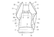
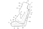
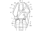
- FIG. 1A is a diagram showing the airbag in a completed inflation and deployment state (inflation completed state) in the airbag device according to the embodiment, and is a diagram of a seat on which an occupant is seated as seen from the front.
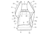
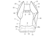
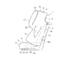
- FIG. 1B is a diagram showing an airbag in a fully inflated state, and is a diagram of a seat with no occupant as viewed from the front.
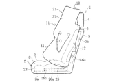
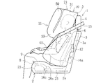
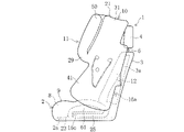
- FIG. 1C is a diagram showing an airbag in a fully inflated state, and is a diagram of a seat with no occupant as viewed from the side of the first side cushion.
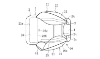
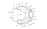
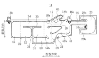
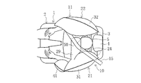
- FIG. 1D is a diagram showing the airbag in a fully inflated state, and is a diagram of the seat with no occupant as viewed from above.
- FIG. 1A is a diagram showing the airbag in a completed inflation and deployment state (inflation completed state) in the airbag device according to the embodiment, and is a diagram of a seat on which an occupant is seated as seen from the front.
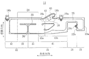
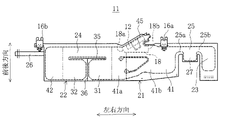
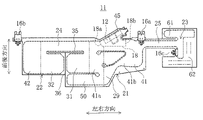
- FIG. 2 is a plan view of the airbag in a flat state in the airbag device according to the embodiment.
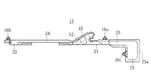
- FIG. 3 is a plan view of the airbag in the stowed configuration.
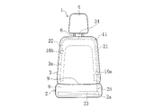
- FIG. 4 is a front view of the seat showing the stowed state of the airbag.
- FIG. 5 is a plan view of an airbag in a flat state in an airbag device according to a first modified example of the embodiment.
- FIG. 6A is a diagram showing an airbag in a fully inflated state in an airbag device according to a first modified example of the embodiment, and is a diagram of a seat with no occupant as viewed from the front.
- FIG. 6B is a diagram showing the airbag in a fully inflated state, and is a diagram of the seat with no occupant as viewed from above.
- FIG. 7 is a plan view of an airbag placed flat in an airbag device according to a second modification of the embodiment.
- FIG. 8A is a diagram showing an airbag in a fully inflated state in an airbag device according to a second modification of the embodiment, and is a diagram of a seat with no occupant as viewed from the front.
- FIG. 8B is a diagram showing the airbag in a fully inflated state, and is a diagram of the seat with no occupant seen from the side of the first side cushion.
- FIG. 9 is a plan view of an airbag placed flat in an airbag device according to a third modification of the embodiment.
- FIG. 10A is a diagram showing an airbag in a fully inflated state in an airbag device according to a third modification of the embodiment, and is a diagram of a seat with no occupant as viewed from the front.
- FIG. 10B is a diagram showing the airbag in a fully inflated state, and is a diagram of the seat with no occupant seen from the side of the first side cushion.
- FIG. 11 is a plan view of an airbag placed flat in an airbag device according to a fourth modification of the embodiment.
- FIG. 12A is a diagram showing an airbag in a fully inflated state in an airbag device according to a fourth modification of the embodiment, and is a diagram of a seat on which an occupant is seated as seen from the front.
- FIG. 12B is a diagram showing the airbag in a fully inflated state, and is a diagram of the seat on which the occupant is seated, viewed from the side of the first side cushion.
- FIG. 12C is a diagram showing the airbag in a fully inflated state, and is a diagram of the seat on which the occupant is seated, viewed from above.
- FIG. 13 is a plan view of an airbag placed flat in an airbag device according to a fifth modification of the embodiment.
- FIG. 14A is a diagram showing an airbag in a fully inflated state in an airbag device according to a fifth modification of the embodiment, and is a diagram of a seat on which an occupant is seated as seen from the front.
- FIG. 14B is a diagram showing the airbag in a fully inflated state, and is a diagram of the seat with no occupant seen from the side of the first side cushion.
- FIG. 15 is a plan view of an airbag placed flat in an airbag device according to a sixth modification of the embodiment.
- FIG. 16A is a diagram showing an airbag in a fully inflated state in an airbag device according to a sixth modification of the embodiment, and is a diagram of a seat on which an occupant is seated as seen from the front.
- FIG. 16B is a diagram showing the airbag in a fully inflated state, and is a diagram of the seat with no occupant seen from the side of the first side cushion.
- the terms “upper” and “upper” refer to the direction of the head of the occupant 5 seated in the normal position of the seat 1, and the terms “lower” and “lower” refer to the direction of the feet of the occupant 5.
- the “normal position” is the center position of the seat cushion 2 in the seat 1 in the left-right direction, and the position where the back of the occupant 5 is in contact with the backrest portion 3 from above and below.
- the terms “front” and “front side” may refer to the front direction of the occupant 5 seated in the normal position of the seat 1, and the terms “rear” and “rear side” may refer to the back direction of the occupant 5.
- left and right side may refer to the left side of the occupant 5 seated in the normal position of the seat 1, and the terms “right” and “right side” may refer to the right side of the occupant 5.
- the occupant 5 is assumed to be a WorldSID (World Side Impact Dummy) AM50 (50th percentile of American adult males).
- a pair of side cushions 21 and 22 provided on both sides of a vehicle seat 1 and a seat surface airbag cushion 23 incorporated in the seat cushion 2 are integrated into one airbag 11. It is a bag device 10 .
- the seat 1 on which the airbag device 10 is mounted will be described below.
- the seat 1 includes a seat cushion 2 and a backrest portion 3, as shown in FIGS. 1A to 1D.
- a headrest 4 is attached to the upper end portion of the backrest portion 3 via a rod-shaped support member 6 .
- the seat 1 may be one in which the backrest portion 3 and the headrest 4 are integrally formed.
- the side closer to the door for seat 1 may be called the "near side”
- the side farther from the door for seat 1 may be called the "far side”.
- a pad 8 is provided on the upper side of a seat pan (lower support member) 2a forming part of the seat frame, and the pad 8 is covered with a skin material 9.
- the skin material 9 is exposed on the seat surface (upper surface) of the seat cushion 2 .
- a pad 8 is provided on the front side of a seat back frame 3a forming part of the seat frame, and the pad 8 is covered with a skin material 9. As shown in FIG.
- the airbag device 10 includes an airbag 11 and an inflator 12 (see FIG. 1C).
- the airbag 11 is a fabric bag.
- the inflator 12 is a device that injects gas for inflating the airbag 11 .
- the airbag device 10 provided in the driver's seat or the front passenger's seat which is adjacent to each other on the left and right will be described as an example.
- the airbag 11 includes a first side cushion 21 that inflates and deploys to cover one side of the occupant 5, and an airbag 11 that inflates and deploys to cover the other side of the occupant 5.
- a first duct 24 communicating with the two side cushions 22 and a second duct 25 communicating the first side cushion 21 and the seat airbag cushion 23 are provided.
- the first duct 24 corresponds to a connection member that connects the first side cushion 21 and the second side cushion 22 .
- the second duct 25 is a member that connects the first side cushion 21 and the seat airbag cushion 23, and corresponds to a duct portion.
- the first side cushion 21 is provided on the near side of the seat 1.
- the rear side of the first side cushion 21 is fixed to the near side of the seat 1.
- the first side cushion 21 extends forward from its fixed position to the seat 1, as shown in FIGS. 1C and 1D.
- the first side cushion 21 includes a first head cushion portion 31 that inflates and deploys so as to cover one side of the head of the occupant 5, and one side of the torso (from the shoulder to the abdomen) of the occupant 5. and a first body cushion portion 41 that inflates and deploys to cover.
- the first head cushion portion 31 stands obliquely upward in a rearward direction from the front portion of the first body cushion portion 41 .
- the second side cushion 22 is provided on the far side of the seat 1.
- the rear side of the second side cushion 22 is fixed to the far side of the seat 1.
- the second side cushion 22 extends forward from its fixed point to the seat 1, as shown in FIG. 1D.
- the second side cushion 22 includes a second head cushion portion 32 that inflates and deploys so as to cover the other side portion of the head of the occupant 5, and a second side cushion portion 32 that covers the other side portion of the torso (shoulder portion) of the occupant 5. and a second body cushion portion 42 that inflates and deploys.
- the second head cushion portion 32 stands obliquely upward in a rearward direction from the front portion of the second body cushion portion 42 .
- the seat surface airbag cushion 23 inflates at the front portion within the seat cushion 2 to raise the front portion of the seat surface.
- the front portion of the seat cushion 2 refers to the front half of the seating area of the seat cushion 2 (the area of the upper surface of the seat cushion 2 other than the area covered by the backrest portion 3).
- the seat airbag cushion 23 is inflated, for example, between the seat pan 2a and the pad 8, as shown in FIG. 1C.
- the seat airbag cushion 23 extends from one side of the seat cushion 2 to the other side in the width direction of the seat 1, as shown in FIG. 1D.
- the installation range of the seat airbag cushion 23 may extend to the rear portion of the seat cushion 2 .
- the first duct 24 is a tubular duct through which gas can flow.
- the first duct 24 extends in the width direction of the seat 1 along the upper end surface of the backrest portion 3, as shown in FIG. 1B.
- One end of the first duct 24 opens into the first side cushion 21 and the other end of the first duct 24 opens into the second side cushion 22 .
- the first duct 24 is positioned below the top of the head of the occupant 5 in the height range above the seat 1 .
- the first duct 24 is positioned in front of the gap between the backrest portion 3 and the headrest 4 .
- the first duct 24 is thick enough to cover the range from the upper end of the backrest 3 to the lower end of the headrest 4 .
- the "height range of the upper portion of the seat 1" refers to the range above the center of the backrest portion 3 in the vertical direction.
- the second duct 25 is a tubular duct through which gas can flow.
- the second duct 25 has a gas passage area (cross-sectional area in an expanded state) smaller than that of the first duct 24 .
- the gas passage area of the second duct 25 may be larger than that of the first duct 24 or may be the same as that of the first duct 24 .
- the second duct 25 extends in the front-rear direction inside one side portion (near-side side portion) of the seat cushion 2 and is connected to the seat airbag cushion 23 at the front portion of the seat cushion 2 .
- the second duct 25 is positioned, for example, between the seat pan 2a and the pad 8, as indicated by the dashed line in FIG. 1C.
- the side portion of the seat cushion 2 is the vicinity of the side surface of the seat cushion 2, for example, a range of 10 cm from the side surface of the seat cushion 2. As shown in FIG.
- the airbag 11 is a bag formed by stacking two base fabrics of the same shape and size and sewing them at predetermined locations such as the outer periphery. In FIG. 2, the sewing location is represented by a thick dashed line. As shown in FIG. 2, the airbag 11 has main body portions 21 and 22 formed of a first side cushion 21 and a second side cushion 22 and having a laterally long substantially rectangular shape. In the description of the airbag 11 in the flat state, the longitudinal direction of the main body portions 21 and 22 of the airbag 11 is referred to as the "left-right direction" and the widthwise direction as the "front-rear direction". The side where 22 is fixed to the seat 1 (the upper side in FIG. 2) is called the “rear side", and the opposite side is called the "front side".
- the airbag 11 includes a first duct 24 extending in the left-right direction, a first side cushion 21 connected to one end of the first duct 24, a second side cushion 22 connected to the other end of the first duct 24, A second duct 25 connected to the outer end of the first side cushion 21 (the right end in FIG. 2) and a seat airbag cushion 23 connected to the outer end of the second duct 25 (the right end in FIG. 2).
- the first duct 24, the first side cushion 21, and the second side cushion 22 are rearward when the upper side in FIG. 2 is in an inflated state.
- the second duct 25 and the seat airbag cushion 23 are in a fully inflated state, and the right side (symbol 23a side) in FIG. Far side.
- the first duct 24 has a horizontally long, substantially rectangular shape.
- the first duct 24 is provided behind the airbag 11 .
- the front end of the first duct 24 (the position of the horizontal slit 35 in FIG. 2) is located behind the front ends of the first side cushion 21 and the second side cushion 22 .
- the dimension (thickness) of the first duct 24 in the front-rear direction is half or less of the dimension in the front-rear direction of each of the side cushions 21 and 22 .
- the first side cushion 21 has a first body cushion portion 41 positioned outside the first duct 24 in the left-right direction, and a first head cushion portion 31 positioned in front of the first duct 24 .
- the first body cushion portion 41 extends forward beyond the front end of the first duct 24 .
- the first head cushion portion 31 extends inward in the left-right direction (to the left in FIG. 2) from a portion of the first body cushion portion 41 that extends forward.
- the first head cushion part 31 has a substantially rectangular shape.
- the first head cushion portion 31 is adjacent to the first duct 24 via a horizontal slit 35 extending in the left-right direction.
- the first body cushion portion 41 has a laterally long substantially rectangular shape. Strictly speaking, the first body cushion portion 41 is an outer portion in the left-right direction, and the dimension in the front-rear direction gradually decreases toward the outer end.
- a portion of the first body cushion portion 41 on the side of the first duct 24 constitutes an upper cushion portion 41 a for protecting the side portion of the shoulder of the occupant 5 .
- a portion of the first body cushion portion 41 on the second duct 25 side constitutes a lower cushion portion 41 b for protecting the side portions of the chest and abdomen of the occupant 5 .
- "rectangle" includes a square.
- a housing portion 45 for the inflator 12 is formed on the rear side of the first body cushion portion 41 .
- a gas guide 18 is provided in the storage portion 45 .
- the gas guide 18 has a first outlet 18a that opens to the upper cushion portion 41a and a second outlet 18b that opens to the lower cushion portion 41b as outlets for the gas injected from the inflator 12 .
- the first body cushion portion 41 which takes less time to protect the occupant 5 from the collision, can be inflated and deployed ahead of the other cushion portions.
- the second side cushion 22 has a second body cushion portion 42 positioned outside the first duct 24 in the left-right direction, and a second head cushion portion 32 positioned in front of the first duct 24 .
- the second body cushion portion 42 extends forward beyond the front end of the first duct 24 .
- the second head cushion portion 32 extends inward in the left-right direction (to the right in FIG. 2) from a portion of the second body cushion portion 42 that extends forward.
- the second head cushion part 32 has a substantially rectangular shape.
- the second head cushion portion 32 is adjacent to the first duct 24 via the lateral slit 35 described above.
- the second body cushion portion 42 has a substantially rectangular shape that is slightly vertically long.
- the second body cushion part 42 is a part for protecting the side part of the shoulder of the occupant 5 .
- the tips of the first head cushion part 31 and the second head cushion part 32 are adjacent to each other via a longitudinal slit 36 extending in the front-rear direction.
- the first head cushion part 31 and the second head cushion part 32 are formed symmetrically with the vertical slit 36 interposed therebetween.
- the vertical slit 36 is a slit extending in the front-rear direction from the front end of the airbag 11 and connected to the center position of the horizontal slit 35 on the rear side.
- the horizontal slits 35 extend leftward and rightward from the positions of the rear ends of the vertical slits 36 .
- Combining the horizontal slit 35 and the vertical slit 36 forms a substantially T-shaped notch.
- each of the slits 35 and 36 is a cut with almost no gap, but it may be a cut with a certain amount of gap.
- the second duct 25 has a horizontally long, substantially rectangular shape.
- the second duct 25 is provided behind the airbag 11 .
- the second duct 25 extends from the rear portion of the first side cushion 21 and connects to the rear portion of the seat airbag cushion 23 .
- the front end of the second duct 25 is located behind the front ends of the first side cushion 21 and the seat airbag cushion 23 .
- the second duct 25 is shorter in size (thickness) in the front-rear direction than the first duct 24 .
- the longitudinal dimension of the second duct 25 may be longer than that of the first duct 24 or may be the same as that of the first duct 24 .
- the seat airbag cushion 23 has a substantially rectangular shape.
- the seat airbag cushion 23 extends forward beyond the front end of the second duct 25 .
- the seat airbag cushion 23 has a dimension in the front-rear direction (the width direction of the seat 1 in the stowed state described later) larger than its dimension in the left-right direction (the front-rear direction of the seat 1 in the stowed state).
- the longitudinal dimension of the seat airbag cushion 23 can be adjusted according to the width of the seat cushion 2 .
- the airbag 11 is provided with a plurality of tabs 16a to 16c as fixing portions for fixing the airbag 11 to the seat frames 2a and 3a of the seat 1 (see FIG. 2).
- the airbag 11 includes a first tab 16a provided in the vicinity of the second duct 25 on the outer peripheral portion on the rear side of the first side cushion 21, and a tab 16a on the outer peripheral portion on the rear side of the second side cushion 22.
- a second tab 16b provided at the outer end (the left end in FIG. 2) and a third tab 16c provided at the inner peripheral portion 23b of the seat airbag cushion 23 are provided.
- FIG. 1 a storage form when the airbag 11 is stored in the seat 1 and a storage state in which the airbag 11 is stored in the seat 1 will be described with reference to FIGS. 3 and 4.
- FIG. 3 a storage form when the airbag 11 is stored in the seat 1 and a storage state in which the airbag 11 is stored in the seat 1 will be described with reference to FIGS. 3 and 4.
- the airbag 11 is stored in the seat 1 by folding the first duct 24, the first side cushion 21, and the second side cushion 22 so that the dimension in the front-rear direction is shortened in the flat state. It becomes a storage form (see FIG. 3).
- the head cushion portions 31 and 32 are folded outward at their roots and overlapped with the body cushion portions 41 and 42, and then rolled from the front side to the rear side.
- a winding method can be adopted.
- other methods such as folding in a bellows shape may be adopted.
- the attachment positions of the tabs 16a and 16b or the bent portions (described later) of the second duct 25 may be wrapped with a cloth material that breaks when the airbag 11 is inflated and deployed.
- the stored airbag 11 is stored in the seat 1 with the first duct 24, the first side cushion 21, and the second side cushion 22 folded along the seatback frame 3a.
- the first duct 24 is stored at the upper end of the backrest portion 3
- the first side cushion 21 is stored at the near side of the seat 1
- the second side cushion 22 is stored at the far side of the seat 1.
- the second duct 25 is housed between the seat pan 2a and the pad 8 on the near-side side of the seat cushion 2 in an unfolded state.
- the second duct 25 extends forward from near the lower end of the seatback frame 3a on the near side.
- the seat airbag cushion 23 is accommodated between the seat pan 2a and the pad 8 in the front portion of the seat cushion 2 in an unfolded state.
- the seat airbag cushion 23 extends from the near side to which the second duct 25 is connected toward the far side.
- the seat airbag cushion 23 has a side 23 a positioned at the outer end in a flat state and extends in the width direction of the seat 1 along the front end of the seat cushion 2 .
- the stowed airbag 11 stowed in the seat 1 is fixed to the seat frames 2a and 3a of the seat 1 at four points, ie, the three tabs 16a to 16c and the stowage portion 45 of the inflator 12.
- the body cushion portions 41 and 42 are fixed to the seatback frame 3a by the first tab 16a and the second tab 16b, respectively.
- the seat airbag cushion 23 is fixed to the seat pan 2a by the third tab 16c at the center of the inner side 23b in the flat state.
- an insertion hole for a stud bolt (not shown) projecting from the inflator 12 is formed in the storage portion 45 .
- the storage portion 45 having the stud bolt passed through the insertion hole is also fixed to the seatback frame 3a.
- the arrangement and number of tabs 16a to 16c are not limited to those of this embodiment.
- the inflator 12 receives a signal from the sensor and injects gas into the first side cushion 21 .
- the first side cushion 21 is inflated and deployed.
- part of the gas injected to the first side cushion 21 is supplied to the second side cushion 22 through the first duct 24 .
- the second side cushion 22 is inflated and deployed.
- part of the gas injected to the first side cushion 21 is supplied to the seat airbag cushion 23 through the second duct 25 .
- the seat airbag cushion 23 is inflated at its installation location.
- the occupant 5 moves to the side where the collision occurred due to the inertial force at the beginning of the collision, and then moves to the opposite side due to the impact force of the collision. Specifically, in the case of a far-side side collision, the occupant 5 collides with the second side cushion 22 at the beginning of the collision. Along with this collision, the first side cushion 21 connected through the first duct 24 moves to the far side together with the second side cushion 22 . After that, when the occupant 5 moves to the side opposite to the initial stage of the collision, the occupant 5 collides with the first side cushion 21 .
- the occupant 5 collides with the first side cushion 21 at the beginning of the collision, and the first side cushion 21 and the second side cushion 22 move to the near-side. After that, when the occupant 5 moves to the side opposite to the initial stage of the collision, the occupant 5 collides with the second side cushion 22 .
- the first duct 24 is positioned in the height range where the occupant 5 collides with the side cushions 21 and 22 at the initial stage of collision. Therefore, a lateral load acts on the first duct 24, and both side cushions 21 and 22 move laterally together. As a result, the travel distance of the occupant 5 moving in the opposite direction from the initial stage of the collision until it collides with the other side cushions 21 and 22 is shortened, and the occupant 5 is restrained early. In addition, since the side cushions 21 and 22 with which the occupant 5 collides at the initial stage of the collision are restrained to some extent by the first duct 24, the amount of outward movement of the seat 1 is suppressed, and the collision occurrence side is also restrained early. In this manner, the side cushions 21 and 22 exhibit occupant restraint performance in response to a side collision of the vehicle.
- the airbag device 10 can quickly restrain the occupant 5 because the side cushions 21 and 22 on both sides behave together.
- the seat surface airbag cushion 23 inflates, causing the seat cushion 2 to move forward.
- the front portion of the surface is raised across the width.
- the raised portion of the seat surface lifts and restrains the thighs of the occupant 5, restricting forward movement of the lumbar region of the occupant 5.
- the seat airbag cushion 23 exerts the occupant restraint performance in response to a frontal collision.
- the pair of side cushions 21 and 22 and the seat airbag cushion 23 can be inflated with one inflator 12.
- the installation space for the inflator 12 is reduced compared to the case where an inflator is installed on each cushion.
- the entire airbag 11 can be inflated by one inflator 12, an increase in the number of parts of the airbag device 10 can be suppressed.
- an inflator is arranged below the airbag built into the seat cushion.
- a mounting space for the inflator is required in the frame on the seat pan side.
- there is no need for an installation space for the inflator 12 in the seat cushion 2 and it is possible to widen the range of packaging and design of various equipment in the seat 1.
- the airbag 11 having the side cushions 21 and 22 that inflate and deploy close to the occupant 5 is integrated with the seat airbag cushion 23 that inflates close to the occupant 5.
- the structure for the airbag provided in the seat 1 can be efficiently simplified. Further, since each of the cushions 21 to 23 inflates at a position close to the occupant 5, high restraint performance can be exhibited.
- the second duct 25 is built into one side of the seat cushion 2 .
- the place where the second duct 25 is built is, for example, a passenger car equipped with an automatic driving function, and even if the passenger 5 takes a free posture, the weight of the passenger 5 is less likely to act thereon. Therefore, the flow of gas in the second duct 25 is less likely to be hindered by the weight of the occupant 5 , and the seat airbag cushion 23 can be smoothly inflated regardless of the posture of the occupant 5 .
- the second duct 25 is attached to the first side cushion 21 to which the inflator 12 is attached. Therefore, the gas injected from the inflator 12 can be quickly supplied to the seat airbag cushion 23, and the seat airbag cushion 23 can be quickly inflated.
- the gas in the seat airbag cushion 23 can be released to the first side cushion 21 through the second duct 25. can. That is, the second duct 25 functions as a vent hole. Therefore, installation of a vent hole in the seat airbag cushion 23 can be omitted.
- the third tab 16c is attached to the rear portion of the seat airbag cushion 23 to fix the rear portion to the seat pan 2a. Therefore, even if the thigh of the occupant 5 hits the raised portion of the seat airbag cushion 23 from behind in the event of a frontal collision or the like, the forward displacement of the seat airbag cushion 23 is suppressed. can do.
- the airbag device 10 can be installed on either the front seat or the rear seat of the vehicle, and can also be installed on the seat of a single-seat vehicle. Further, since the airbag device 10 does not depend on the layout of the vehicle, it is possible to modularize part or all of the airbag device 10 so that it can be applied to a plurality of vehicle types.
- the airbag device 10 further includes a second connection member 26 that connects the second side cushion 22 and the seat airbag cushion 23 .
- the second connection member 26 is a string-like or thin band-like member (for example, a tether).
- one end of the second connection member 26 is fixed at a position near the rear of the outer end 42 a of the second body cushion portion 42 .
- a non-inflatable portion 23d for fixing the other end of the second connecting member 26 is provided continuously from the seat airbag cushion 23. As shown in FIG.
- the non-inflatable portion 23d is provided on the side opposite to the side to which the second duct 25 is connected.
- the second connecting member 26 passes through the inside of the skin material 9 of the backrest portion 3 and the inside of the skin material 9 of the seat cushion 2 when the airbag 11 is stored in the seat 1 .
- the second connecting member 26 can pass between the seat back frame 3a and the pad 8 in the backrest portion 3, and can pass between the seat pan 2a and the pad 8 in the seat cushion 2.
- the other end of the second connecting member 26 is fixed to the non-inflatable portion 23d arranged on the far side by sewing or the like (see FIGS. 6A and 6B).
- the second connection member 26 extends downward from the end of the second body cushion portion 42 along the far side of the seat back frame 3 a in the backrest portion 3 and reaches the seat cushion 2 . .
- the second connecting member 26 bends forward within the seat cushion 2 and extends forward on the far side to reach the non-inflatable portion 23d.
- the reaction force of the first side cushion 21 acts through the second duct 25 and the reaction force of the second side cushion 22 acts through the second connection member 26 .
- the first side cushion 21 is fixed to the seat back frame 3a by the first tab 16a near the second duct 25, and the second side cushion 22 is fixed to the seat back frame 3a by the second tab 16b near the second connecting member 26. It is fixed to the back frame 3a, and each reaction force described above becomes relatively strong. Therefore, it is possible to suppress forward displacement of the seat airbag cushion 23 . Further, the fixing portion (third tab 16c) for fixing the seat airbag cushion 23 to the seat pan 2a can be omitted.
- the structure of the seat pan 2a needs to be changed accordingly, and it is preferable to dispose the seat airbag cushion 23 right above the seat pan 2a. Fixing by 16c is easy.
- the third tab 16c is omitted, the seat pan 2a does not need to be structurally changed, and the seat airbag cushion 23 can be easily arranged between the pad 8 and the upholstery 9.
- FIG. the shape of the seat surface can easily follow the shape of the seat airbag cushion 23 when inflated, and the performance of restraining the occupant 5 in response to a frontal collision can be improved.
- the airbag device 10 further includes a seat side cushion 27 that inflates so as to raise the side of the seat of the seat cushion 2 (the side on the near side).
- the seat side cushion 27 is formed continuously with the second duct 25, as shown in FIG.
- the seat side cushion 27 is more flexible than the inlet 25a on the side of the first side cushion 21 and the outlet 25b on the side of the seat airbag cushion 23.
- the duct diameter of the portion where is formed (the dimension in the front-rear direction when placed flat) is large.
- the airbag device 10 includes a first seat side cushion 28a that inflates so as to raise one side of the seat surface of the seat cushion 2, and the other side of the seat cushion 2. and a second seat side cushion 28b that expands to raise the seat.
- the seat side cushions 28 a and 28 b are formed continuously with the seat airbag cushion 23 .
- the first seat side cushion 28a extends toward the first side cushion 21 from the rear portion (the upper portion in FIG. 9) of the inner portion of the outer circumference of the seat airbag cushion 23.
- the second seat side cushion 28b extends toward the first side cushion 21 from the front portion of the inner portion (lower portion in FIG. 9).
- the second duct 25 extends so as to be adjacent to the front side of the first seat side cushion 28a, and is connected to the seat airbag cushion 23 immediately in front of the first seat side cushion 28a.
- the gas when gas is injected from the inflator 12, the gas is supplied to the seat side cushions 28a and 28b through the seat airbag cushion 23, and as shown in FIGS.
- the seat side cushions 28a, 28b are inflated to raise each side of the seat cushion 2's seat surface.
- the seat side cushions 28a and 28b extend rearward from the rear portion of the seat airbag cushion 23.
- both the occupant 5 trying to move to the near side and the occupant 5 trying to move to the far side at the time of a side collision hit the portion raised by the seat side cushion 28a or the seat side cushion 28b.
- the seat side cushions 27 of the second modified example may be provided instead of the first seat side cushions 28a.
- the airbag device 10 further includes a front head protection cushion 50 that inflates and deploys in front of the head of the occupant 5 .
- the front head protection cushion 50 communicates with the first side cushion 21 via the third duct 29 .
- the third duct 29 corresponds to a third connecting member.
- the front head protection cushion 50 is arranged so as to be adjacent to the front side of the first head cushion portion 31 .
- the inlet of the front head protection cushion 50 is connected to the front portion of the first side cushion 21 via the third duct 29 .
- the gas when gas is injected from the inflator 12, the gas is supplied to the front head protection cushion 50 via the first side cushion 21 and the third duct 29, as shown in FIGS. 12A to 12C. , the head front protection cushion 50 is inflated and deployed. In the inflated state, the third duct 29 extends inward from the inner surface of the first side cushion 21, and the front head protection cushion 50 extends upward from the connection point of the third duct 29. As shown in FIG.
- the thick dashed lines in FIGS. 12A and 12B represent sewing locations.
- the first side cushion 21 and the third duct 29 are interposed between the seat belt 15 and the occupant 5 in the fully inflated state. .
- the third duct 29 is received by the seat belt 15 . Therefore, a reaction force can be obtained to some extent when the head of the occupant 5 collides with the front head protection cushion 50 at the time of a frontal collision, etc., and the restraint performance of the occupant 5 in response to the frontal collision can be improved.
- the airbag device 10 further includes a first thigh outer cushion 61 that raises the outer portion of the seating surface of the seat cushion 2 below the thigh of the occupant 5 on the near side.
- the first outer thigh cushion 61 is provided only on the outer portion in the left-right direction of the lower side of the thigh on the near side of the occupant 5, and does not exist on the lower side of the thigh on the far side.
- the first outer thigh cushion 61 is slightly inflated into a vertically long shape and extends from the thigh of the occupant 5 to the waist.
- the seat surface airbag cushion 23 does not inflate to the entire lateral direction of the seat surface of the seat cushion 2, and the first thigh outer cushion 61 is positioned at the outer portion below the thigh on the near side of the occupant 5. Inflate.
- the first thigh outer cushion 61 extends toward the first side cushion 21 at the rear portion of the seat airbag cushion 23 (upper portion in FIG. 13).
- the second duct 25 is connected to the first outer thigh cushion 61 .
- a non-inflatable portion 62 is formed in the front portion (lower portion in FIG. 13) of the seat airbag cushion 23 where the first thigh outer cushion 61 does not exist.
- the gas when gas is injected from the inflator 12, the gas is supplied to the first thigh outer cushion 61, and as shown in FIGS. 14A and 14B, the first thigh outer cushion 61 is inflated. to raise the outer portion under the thigh of the occupant 5 on the near side.
- the first outer thigh cushion 61 In the fully inflated state, the first outer thigh cushion 61 extends from the outer portion under the thigh of the occupant 5 to the waist.
- the first side cushion 21 expands, and at the same time, the outer portion below the thigh on the near side of the occupant 5 expands.
- the body of 5 can be tilted away from the side door.
- the first outer thigh cushion 61 does not need to tilt the body of the occupant 5 completely.
- the inflated first thigh outer cushion 61 moderately tilts the body of the occupant 5 to prevent the occupant 5 from moving in the collision direction due to inertia and colliding with the side door. .
- the airbag device 10 includes, in addition to the above-described first thigh outer cushion 61, a second outer thigh cushion 61 that raises an outer portion of the seating surface of the seat cushion 2 below the thigh on the far side side of the occupant 5.
- An outer thigh cushion 63 is further provided.
- the second thigh outer cushion 63 is provided on the outer portion in the left-right direction of the lower thigh of the occupant 5 on the far side.
- the second outer thigh cushion 63 is slightly inflated into a vertically long shape and extends from the thigh of the occupant 5 to the waist.
- the first thigh outer cushion 61 extends toward the first side cushion 21 at the rear portion of the seat airbag cushion 23 (upper portion in FIG. 15).
- the second thigh outer cushion 63 extends toward the first side cushion 21 side.
- the fourth duct 64 is connected to the second duct 25 and branches the first thigh outer cushion 61 and the second thigh outer cushion 63 .
- the fourth duct 64 corresponds to a fourth connecting member.
- a non-inflatable portion 62 is formed at the right end portion of the seat airbag cushion 23 .
- An active valve 65 is provided in the fourth duct 64 .
- the active valve 65 is connected to a control device (not shown) and can control opening and closing of the fourth duct 64 according to the direction in which the collision has occurred. Specifically, when a collision occurs from the near side, the active valve 65 opens the first thigh outer cushion 61 side and closes the second thigh outer cushion 63 side. Conversely, when a collision occurs from the far side, the second thigh outer cushion 63 side is opened, while the first thigh outer cushion 61 side is closed.
- the active valve 65 and the controller that controls the opening/closing of the fourth duct 64 by operating the active valve 65 correspond to opening/closing control means.
- FIGS. 16A and 16B show a state in which the second thigh outer cushion 63 is inflated and the outer portion below the thigh on the far side side of the occupant 5 is raised. In the fully inflated state, the second thigh outer cushion 63 extends from the outer portion below the thigh of the occupant 5 to the waist.
- the second side cushion 22 expands, and at the same time, the outer portion below the far side thigh of the occupant 5 expands, pushing the waist of the occupant 5.
- the body of the occupant 5 can be moderately inclined in the direction away from the passenger seat side.
- a first outer thigh cushion 61 and a second outer thigh cushion 63 are provided on the seat airbag cushion 23 and are separated into left and right.
- the direction in which the body of the occupant 5 is tilted at the time of collision can be switched.
- the second side cushion 22 may be omitted.
- the airbag 11 may be an assembly of the near-side side cushion 21 and the seat airbag cushion 23 .
- the airbag 11 may be a combination of the side cushion 22 on the far side and the airbag cushion 23 for the seat surface.
- the second duct 25 is provided on the far side and allows the side cushion 22 on the far side and the seat airbag cushion 23 to communicate with each other.
- the connecting member 24 that connects the first side cushion 21 and the second side cushion 22 is a duct, but the connecting member 24 may be a member through which gas cannot flow.
- a second inflator may be attached to the second side cushion 22, or a bifurcated pipeline may be used so that gas is supplied from one inflator to both side cushions 21 and 22.
- the airbag device 10 may be constructed.
- the inflator 12 is attached to the first side cushion 21 in the above embodiment, the inflator 12 may be attached to the second side cushion 22 . Further, for example, when the volume of the airbag 11 is large as in the fourth modification, one inflator 12 may be attached to each of the first side cushion 21 and the second side cushion 22 .
- the seat airbag cushion 23 is stored in the seat cushion 2 in an unfolded state without being folded, but the seat airbag cushion 23 may be stored in a folded state.
- only one of the first side cushion 21 and the second side cushion 22 may be provided with the head cushion portions 31 and 32 .
- the present invention can be applied to an airbag device or the like that protects the sides of an occupant.
Landscapes
- Engineering & Computer Science (AREA)
- Mechanical Engineering (AREA)
- Aviation & Aerospace Engineering (AREA)
- Transportation (AREA)
- Air Bags (AREA)
- Seats For Vehicles (AREA)
Abstract
La présente invention concerne un dispositif de coussin de sécurité gonflable ayant une capacité de retenue d'occupant de véhicule pour gérer une collision latérale d'un véhicule, et une capacité de retenue d'occupant de véhicule pour gérer une collision frontale, l'espace requis pour monter le dispositif de coussin de sécurité gonflable étant réduit. Un dispositif de coussin de sécurité gonflable 10 comprend : un coussin de sécurité gonflable 11 comportant un coussin latéral 21 qui se dilate et se déploie de façon à recouvrir une zone latérale d'un occupant 5 assis sur un siège 1 d'un véhicule ; et un dispositif de gonflage 12 qui injecte un gaz pour dilater le coussin latéral 21. Le coussin de sécurité gonflable 11 comprend en outre : un coussin de coussin de sécurité gonflable de surface de siège 23 qui se dilate et soulève une surface de siège d'un coussin de siège 2 de telle sorte qu'un mouvement vers l'avant de la taille de l'occupant 5 est limité ; et une partie de conduit 25 pour relier le coussin latéral 21 au coussin de coussin de sécurité gonflable de surface de siège 23.
Priority Applications (1)
| Application Number | Priority Date | Filing Date | Title |
|---|---|---|---|
| JP2023511004A JP7555477B2 (ja) | 2021-04-02 | 2022-03-22 | エアバッグ装置 |
Applications Claiming Priority (2)
| Application Number | Priority Date | Filing Date | Title |
|---|---|---|---|
| JP2021-063394 | 2021-04-02 | ||
| JP2021063394 | 2021-04-02 |
Publications (1)
| Publication Number | Publication Date |
|---|---|
| WO2022210077A1 true WO2022210077A1 (fr) | 2022-10-06 |
Family
ID=83456118
Family Applications (1)
| Application Number | Title | Priority Date | Filing Date |
|---|---|---|---|
| PCT/JP2022/013067 Ceased WO2022210077A1 (fr) | 2021-04-02 | 2022-03-22 | Dispositif de coussin de sécurité gonflable |
Country Status (2)
| Country | Link |
|---|---|
| JP (1) | JP7555477B2 (fr) |
| WO (1) | WO2022210077A1 (fr) |
Cited By (1)
| Publication number | Priority date | Publication date | Assignee | Title |
|---|---|---|---|---|
| WO2025041776A1 (fr) * | 2023-08-23 | 2025-02-27 | オートリブ ディベロップメント エービー | Procédé de fabrication de dispositif de coussin gonflable de sécurité de véhicule et dispositif de coussin gonflable de sécurité de véhicule |
Citations (7)
| Publication number | Priority date | Publication date | Assignee | Title |
|---|---|---|---|---|
| JP2005239129A (ja) * | 2004-02-27 | 2005-09-08 | Takata Corp | 車両乗員保護システムおよびインフレータ |
| JP2007091083A (ja) * | 2005-09-29 | 2007-04-12 | Toyoda Gosei Co Ltd | エアバッグ装置 |
| JP2008114648A (ja) * | 2006-11-01 | 2008-05-22 | Nissan Motor Co Ltd | 側面衝突時の乗員保護装置 |
| JP2010064632A (ja) * | 2008-09-11 | 2010-03-25 | Toyota Motor Corp | 車両用乗員拘束装置 |
| WO2021100382A1 (fr) * | 2019-11-22 | 2021-05-27 | 株式会社ダイセル | Dispositif de coussin de sécurité gonflable |
| WO2021166564A1 (fr) * | 2020-02-21 | 2021-08-26 | 株式会社ダイセル | Structure d'accouplement, dispositif de coussin gonflable de sécurité et siège de véhicule |
| JP2022017983A (ja) * | 2020-07-14 | 2022-01-26 | 株式会社ダイセル | 車両用シート、及び乗員拘束装置 |
-
2022
- 2022-03-22 JP JP2023511004A patent/JP7555477B2/ja active Active
- 2022-03-22 WO PCT/JP2022/013067 patent/WO2022210077A1/fr not_active Ceased
Patent Citations (7)
| Publication number | Priority date | Publication date | Assignee | Title |
|---|---|---|---|---|
| JP2005239129A (ja) * | 2004-02-27 | 2005-09-08 | Takata Corp | 車両乗員保護システムおよびインフレータ |
| JP2007091083A (ja) * | 2005-09-29 | 2007-04-12 | Toyoda Gosei Co Ltd | エアバッグ装置 |
| JP2008114648A (ja) * | 2006-11-01 | 2008-05-22 | Nissan Motor Co Ltd | 側面衝突時の乗員保護装置 |
| JP2010064632A (ja) * | 2008-09-11 | 2010-03-25 | Toyota Motor Corp | 車両用乗員拘束装置 |
| WO2021100382A1 (fr) * | 2019-11-22 | 2021-05-27 | 株式会社ダイセル | Dispositif de coussin de sécurité gonflable |
| WO2021166564A1 (fr) * | 2020-02-21 | 2021-08-26 | 株式会社ダイセル | Structure d'accouplement, dispositif de coussin gonflable de sécurité et siège de véhicule |
| JP2022017983A (ja) * | 2020-07-14 | 2022-01-26 | 株式会社ダイセル | 車両用シート、及び乗員拘束装置 |
Cited By (1)
| Publication number | Priority date | Publication date | Assignee | Title |
|---|---|---|---|---|
| WO2025041776A1 (fr) * | 2023-08-23 | 2025-02-27 | オートリブ ディベロップメント エービー | Procédé de fabrication de dispositif de coussin gonflable de sécurité de véhicule et dispositif de coussin gonflable de sécurité de véhicule |
Also Published As
| Publication number | Publication date |
|---|---|
| JPWO2022210077A1 (fr) | 2022-10-06 |
| JP7555477B2 (ja) | 2024-09-24 |
Similar Documents
| Publication | Publication Date | Title |
|---|---|---|
| KR101781387B1 (ko) | 자동차의 파 사이드 에어백 장치 | |
| JP5999061B2 (ja) | 座席搭載エアバッグ装置及び車両用シート | |
| KR102545853B1 (ko) | 루프탑 에어백 장치 | |
| US12337784B2 (en) | Airbag device and vehicle seat | |
| JP7288510B2 (ja) | エアバッグ装置 | |
| JP6426553B2 (ja) | 乗員保護装置 | |
| JP5781985B2 (ja) | サイドエアバッグ装置 | |
| KR102661047B1 (ko) | 에어백 장치 | |
| US20170072893A1 (en) | Far side airbag device and vehicle seat | |
| JP7542641B2 (ja) | エアバッグ装置 | |
| JPWO2006049101A1 (ja) | サイドエアバッグ装置及びサイドエアバッグシステム | |
| JP7827192B2 (ja) | エアバッグ装置及び乗員保護装置 | |
| JP2024058409A (ja) | エアバッグ装置及び乗員保護装置 | |
| JP7411115B2 (ja) | エアバッグ装置 | |
| JP2024058404A (ja) | エアバッグ装置及び乗員保護装置 | |
| JP2019059381A (ja) | ファーサイドエアバッグ装置 | |
| JP6517662B2 (ja) | 乗員保護装置 | |
| JP7555477B2 (ja) | エアバッグ装置 | |
| JP7555481B2 (ja) | エアバッグ装置 | |
| JP2022154365A (ja) | ファーサイドエアバッグ装置 | |
| JP7530509B2 (ja) | エアバッグ装置 | |
| WO2024095697A1 (fr) | Appareil de retenue d'occupant | |
| JP7592167B2 (ja) | エアバッグ装置 | |
| JP7618807B2 (ja) | エアバッグ装置 | |
| JP7381772B2 (ja) | シート内蔵エアバッグ装置 |
Legal Events
| Date | Code | Title | Description |
|---|---|---|---|
| 121 | Ep: the epo has been informed by wipo that ep was designated in this application |
Ref document number: 22780292 Country of ref document: EP Kind code of ref document: A1 |
|
| WWE | Wipo information: entry into national phase |
Ref document number: 2023511004 Country of ref document: JP |
|
| NENP | Non-entry into the national phase |
Ref country code: DE |
|
| 122 | Ep: pct application non-entry in european phase |
Ref document number: 22780292 Country of ref document: EP Kind code of ref document: A1 |