WO2022224302A1 - 放電加工機 - Google Patents
放電加工機 Download PDFInfo
- Publication number
- WO2022224302A1 WO2022224302A1 PCT/JP2021/015861 JP2021015861W WO2022224302A1 WO 2022224302 A1 WO2022224302 A1 WO 2022224302A1 JP 2021015861 W JP2021015861 W JP 2021015861W WO 2022224302 A1 WO2022224302 A1 WO 2022224302A1
- Authority
- WO
- WIPO (PCT)
- Prior art keywords
- liquid
- electric discharge
- discharge machine
- actuator
- water level
- Prior art date
- Legal status (The legal status is an assumption and is not a legal conclusion. Google has not performed a legal analysis and makes no representation as to the accuracy of the status listed.)
- Ceased
Links
Images

Classifications
-
- G—PHYSICS
- G05—CONTROLLING; REGULATING
- G05D—SYSTEMS FOR CONTROLLING OR REGULATING NON-ELECTRIC VARIABLES
- G05D7/00—Control of flow
- G05D7/06—Control of flow characterised by the use of electric means
- G05D7/0617—Control of flow characterised by the use of electric means specially adapted for fluid materials
- G05D7/0629—Control of flow characterised by the use of electric means specially adapted for fluid materials characterised by the type of regulator means
- G05D7/0635—Control of flow characterised by the use of electric means specially adapted for fluid materials characterised by the type of regulator means by action on throttling means
-
- F—MECHANICAL ENGINEERING; LIGHTING; HEATING; WEAPONS; BLASTING
- F15—FLUID-PRESSURE ACTUATORS; HYDRAULICS OR PNEUMATICS IN GENERAL
- F15B—SYSTEMS ACTING BY MEANS OF FLUIDS IN GENERAL; FLUID-PRESSURE ACTUATORS, e.g. SERVOMOTORS; DETAILS OF FLUID-PRESSURE SYSTEMS, NOT OTHERWISE PROVIDED FOR
- F15B15/00—Fluid-actuated devices for displacing a member from one position to another; Gearing associated therewith
- F15B15/20—Other details, e.g. assembly with regulating devices
- F15B15/202—Externally-operated valves mounted in or on the actuator
-
- B—PERFORMING OPERATIONS; TRANSPORTING
- B23—MACHINE TOOLS; METAL-WORKING NOT OTHERWISE PROVIDED FOR
- B23H—WORKING OF METAL BY THE ACTION OF A HIGH CONCENTRATION OF ELECTRIC CURRENT ON A WORKPIECE USING AN ELECTRODE WHICH TAKES THE PLACE OF A TOOL; SUCH WORKING COMBINED WITH OTHER FORMS OF WORKING OF METAL
- B23H1/00—Electrical discharge machining, i.e. removing metal with a series of rapidly recurring electrical discharges between an electrode and a workpiece in the presence of a fluid dielectric
- B23H1/10—Supply or regeneration of working media
-
- B—PERFORMING OPERATIONS; TRANSPORTING
- B23—MACHINE TOOLS; METAL-WORKING NOT OTHERWISE PROVIDED FOR
- B23H—WORKING OF METAL BY THE ACTION OF A HIGH CONCENTRATION OF ELECTRIC CURRENT ON A WORKPIECE USING AN ELECTRODE WHICH TAKES THE PLACE OF A TOOL; SUCH WORKING COMBINED WITH OTHER FORMS OF WORKING OF METAL
- B23H11/00—Auxiliary apparatus or details, not otherwise provided for
Definitions
- the present invention relates to an electric discharge machine that processes an object by using electric discharge generated by applying a voltage between the object and an electrode.
- Japanese Unexamined Patent Application Publication No. 2000-210818 discloses a wire electric discharge machine in which an actuator is used to open and close a door that can open and close a drainage port of a machining tank.
- this wire electric discharge machine the liquid level of the machining fluid in the machining tank when the machining tank is stopped is detected by the liquid level detection sensor, and the discharge time corresponding to the detected height is calculated.
- an object of the present invention is to provide an electric discharge machine capable of reducing splashing and overflowing of liquid flowing out of a drain port.
- An aspect of the present invention is electrical discharge machining having a liquid tank that stores liquid, a drain valve that opens and closes a drain port for draining the liquid stored in the liquid tank, and an actuator that drives the drain valve. a water level sensor for detecting the water level of the liquid stored in the liquid tank; and a control unit for controlling.
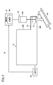
- FIG. 1 is a schematic diagram showing the configuration of an electric discharge machine;
- FIG. It is a figure which shows the structure of the drainage mechanism of an electric discharge machine. It is a relationship graph which shows the relationship between a water level and an opening amount.
- FIG. 1 is a schematic diagram showing the configuration of an electric discharge machine 10 according to an embodiment.
- the X-direction, Y-direction and Z-direction along which the axes of the electrical discharge machine 10 extend are shown.
- the X direction and the Y direction are orthogonal to each other in the plane, and the Z direction is orthogonal to each of the X direction and the Y direction.
- the -Z direction is the direction in which gravity acts (the direction of gravity).
- the electric discharge machine 10 is for machining an object to be machined by means of electric discharge generated by applying a voltage across the object to be machined.
- a workpiece is also called a workpiece or a workpiece.
- the electric discharge machine 10 includes a machine body 12 , a machining fluid processing device 14 , and a control device 16 that controls the processing machine body 12 and the machining fluid processing device 14 .
- the processing machine main body 12 includes a processing tank 17 that stores liquid for immersing the processing object, and electrodes 18 for processing the processing object.
- a table for holding an object to be processed is provided inside the processing tank 17 .
- An electrode 18 is provided which is relatively movable with respect to this table. A voltage is applied between the electrode 18 and the object to be processed while the object to be processed and the electrode 18 are immersed in the liquid stored in the machining tank 17, and the object to be processed is moved by electric discharge generated between the electrodes 18 and the object to be processed. is processed. Sludge can be generated during this processing.
- the machining fluid processing device 14 supplies the machining tank 17 with a fluid (machining fluid) used for machining the object to be processed.
- a fluid machining fluid
- working liquids include deionized water.
- the machining fluid processing device 14 may recover the machining fluid discharged from the machining tank 17 .
- the machining fluid treatment device 14 may remove sludge contained in the recovered machining fluid, or adjust the quality of the recovered machining fluid.
- the working fluid from which the sludge has been removed and the quality of which has been adjusted may be returned to the working tank 17 .
- the electrodes 18 of the processing machine main body 12 may be wire electrodes or shape electrodes for engraving.
- FIG. 1 shows the machine body 12 when the electrode 18 is a wire electrode.
- the processing machine body 12 is provided with a supply system 20 for supplying the electrode 18 toward the workpiece and a recovery system 22 for recovering the electrode 18 that has passed through the workpiece. .
- the supply system 20 includes a wire bobbin 24 around which an unused electrode 18 is wound, a torque motor 26 that applies torque to the wire bobbin 24, a brake shoe 28 that applies a braking force due to friction to the electrode 18, and a brake. It has a brake motor 30 that applies brake torque to the shoe 28, a tension detector 32 that detects the magnitude of the tension of the electrode 18, and an upper die guide 34 that guides the electrode 18 above the workpiece. .
- the recovery system 22 includes a lower die guide 36 that guides the electrode 18 below the workpiece, a pinch roller 38 and a feed roller 40 that can pinch the electrode 18, and a torque that applies torque to the feed roller 40. It has a motor 42 and a collection box 44 for collecting the electrodes 18 conveyed by the pinch rollers 38 and the feed rollers 40 .
- the upper die guide 34 is provided with a support portion 34 a for supporting the electrode 18
- the lower die guide 36 is provided with a support portion 36 a for supporting the electrode 18
- the lower die guide 36 is provided with a guide roller 36 b for changing the direction of the electrode 18 and guiding it to the pinch roller 38 and the feed roller 40 .
- the upper die guide 34 and the lower die guide 36 are arranged in the processing tank 17 during processing and are immersed in the processing liquid stored in the processing tank 17 . Even if at least the upper die guide 34 of the upper die guide 34 and the lower die guide 36 jets clean machining fluid containing no sludge toward the gap between the electrode 18 and the workpiece. good. When clean machining liquid is jetted toward the gap between the electrode 18 and the workpiece, the gap is filled with clean liquid suitable for machining, and sludge generated during machining reduces the machining accuracy. can be reduced.
- FIG. 2 is a diagram showing the configuration of the drainage mechanism 50 of the electric discharge machine 10.
- the drainage mechanism 50 is a mechanism for draining the liquid stored in the liquid tank 52 .
- the liquid bath 52 may be the processing bath 17 .
- the liquid tank 52 may be a dirty water tank or a clean water tank provided in the working fluid processing device 14 .
- the sewage tank is a tank for storing machining fluid (wastewater) containing sludge
- the clean water tank is a tank for storing machining fluid (clean water) from the sewage tank through a filter that removes sludge.
- the drainage mechanism 50 is equipped with a drainage valve 54 , an actuator 56 , a water level sensor 58 and a control section 60 .
- the drain valve 54 is a valve that opens and closes the drain port 62 for draining the liquid stored in the liquid tank 52 .
- the drain port 62 may be provided in the liquid tank 52 or may be provided in a communicating portion 64 that communicates with the liquid tank 52 .
- FIG. 2 shows a case where the communication portion 64 is provided with the drain port 62 .
- the drain valve 54 is arranged so as to cover the drain port 62 provided in the bottom wall 64W of the communicating portion 64 .
- the configuration of the communicating portion 64 is not particularly limited. 2, the communication portion 64 protrudes outward from the side wall 52W of the liquid tank 52, the volume and height of the communication portion 64 are smaller than those of the liquid tank 52, and the inner bottom surface of the communication portion 64 is located inside the liquid tank 52. It is constructed in a box shape with the same height as the bottom.
- the actuator 56 drives the drain valve 54.
- the actuator 56 drives the drain valve 54 so that the opening amount of the drain valve 54 with respect to the drain port 62 is variable.
- the amount of opening of the drain valve 54 is zero.
- the liquid stored in the liquid tank 52 flows out of the drain port 62 through the communicating portion 64 and drops into the water receiving portion of the drain channel 66 under its own weight.
- the drainage channel 66 supplies the liquid that has fallen into the water receiving portion of the drainage channel 66 to, for example, the processing liquid processing device 14 .
- the actuator 56 may be of a pneumatic type, an electric type, a hydraulic type, or a solenoid type.
- the actuator 56 is electric and has a servomotor 56A.
- the servomotor 56A rotates under the control of the controller 60 to vary the amount of opening of the drain valve 54.
- the servomotor 56A drives the drain valve 54 in the direction away from the drain port 62 (in the direction opposite to the direction of gravity) in response to rotation in the positive direction (or the negative direction), thereby increasing the opening amount of the drain valve 54. do.
- the servomotor 56A drives the drain valve 54 in the direction (gravitational direction) toward the drain port 62 according to the rotation in the negative direction (or the positive direction), thereby reducing the opening amount of the drain valve 54 .
- the water level sensor 58 detects the water level of the machining fluid stored in the liquid tank 52 and outputs a signal indicating the water level.
- the water level sensor 58 may be contact type or non-contact type.
- the contact-type water level sensor 58 includes a float type, a capacitance type, an electrode type, a pressure type, a differential pressure type, and the like.
- a radio wave type, an ultrasonic type, or the like can be used as the non-contact type water level sensor 58.
- the float type is configured to convert the rotation angle of a pulley connected via a wire to a float placed on the liquid surface into a level.
- the capacitance equation is configured to convert the change in capacitance between the probe and the vessel wall of the vessel into a level.
- the electrode formula is configured to convert the electrical resistance change between electrodes having a length corresponding to each liquid level into a level.
- a pressure equation is constructed to convert the deformation of the diaphragm due to liquid level into a level.
- the differential pressure formula is configured to convert a change in differential pressure between the liquid pressure and the internal pressure of the container into a level.
- the radio wave type emits microwaves with varying frequencies, measures the frequency difference between the received signal reflected from the liquid surface and the emitted transmitted signal, and converts it into a level.
- the ultrasonic method is configured to measure the time it takes for an ultrasonic wave emitted in a pulse shape to be reflected from an object to be measured and return to convert it into a level.
- the control unit 60 controls the actuator 56 and is provided in the control device 16 .
- the control unit 60 varies the opening amount of the drain valve 54 by controlling the actuator 56 when the machining of the object to be processed is stopped.
- the controller 60 can precisely vary the amount of opening of the drain valve 54 by controlling the servomotor 56A of the actuator 56 .
- control unit 60 controls the actuator 56 so that the opening amount of the drain valve 54 with respect to the drain port 62 increases as the water level detected by the water level sensor 58 decreases. As a result, it is possible to suppress changes in the outflow amount of the liquid that flows out from the drain port 62 per unit time. can be reduced.
- control unit 60 is configured as a computer including a processor and a storage unit 60A. Corresponding information that associates the water level with the amount of opening of the drain valve 54 is stored in the storage unit 60A.
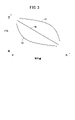
- Fig. 3 is a relationship graph showing the relationship between the water level and the amount of opening.
- This relationship graph includes a linear waveform W1 in which the relationship between the water level and the amount of opening is linear, a convex curved waveform W2 in which the relationship is nonlinear, and a concave concave curved waveform W3 in which the relationship is nonlinear. It is shown.
- the linear waveform W1, the convex curve waveform W2, and the concave curve waveform W3 all have a relationship in which the amount of opening increases as the water level decreases.
- the storage unit 60A stores, as correspondence information, a relational expression or a table indicating at least one relationship among the linear waveform W1, the convex curve waveform W2, and the concave curve waveform W3.
- the table includes a plurality of water levels and opening amounts associated with each of the plurality of water levels.
- the control unit 60 uses the relational expression stored in the storage unit 60A to calculate the opening amount corresponding to the water level detected by the water level sensor 58, and calculates the calculated opening.
- the actuator 56 is controlled so that the amount of As a result, the amount of correspondence information occupying the storage unit 60A can be reduced compared to the case where the table is stored in the storage unit 60A.
- the control unit 60 uses the table to acquire the opening amount corresponding to the water level detected by the water level sensor 58, and operates the actuator 56 so as to achieve the acquired opening amount. Control. Accordingly, the actuator 56 can be controlled without calculating the opening amount, and as a result, the load on the control section 60 can be reduced.
- the control unit 60 controls the actuator 56 based on the correspondence information selected according to the operator's operation or the like from among the plurality of correspondence information.
- control unit 60 may control the actuator 56 so that the flow rate of the liquid discharged from the drain port 62 is constant.
- the control unit 60 controls the actuator 56 based on correspondence information indicating the relationship between the water level at which the flow rate of the liquid discharged from the drain port 62 is constant and the amount of opening. If a flow rate sensor is provided at the drain port 62, the controller 60 may feedback-control the actuator 56 so that the flow rate detected by the flow rate sensor becomes the target value.
- the control unit 60 controls the actuator 56 so that the flow rate of liquid discharged from the drain port 62 is constant, thereby suppressing changes in the amount of liquid discharged from the drain port 62 per unit time. can.
- control unit 60 switches the drive power output to the actuator 56 according to the level of the signal output from the water level sensor 58, so that the lower the water level is, the larger the opening amount of the drain valve 54 is. 56 may be controlled. In this way, the actuator 56 can be controlled without digital computation.
- the present invention comprises a liquid tank (52) for storing liquid, a drain valve (54) for opening and closing a drain port (62) for draining the liquid stored in the liquid tank (52), and a drain valve (54). and an actuator (56) for driving the electrical discharge machine (10).
- the electric discharge machine (10) includes a water level sensor (58) for detecting the water level of the liquid stored in the liquid tank (52), and the lower the water level detected by the water level sensor (58), the more the drain valve (54) opens. a controller (60) for controlling the actuator (56) to increase the amount. As a result, it is possible to suppress a change in the amount of liquid flowing out from the drain port (62) per unit time. splashing and flooding can be reduced.
- the electric discharge machine (10) includes a storage unit (60A) that stores correspondence information that associates the water level with the amount of opening, and the control unit (60) corresponds to the water level detected by the water level sensor (58).
- the actuator (56) may be controlled such that the amount of opening is such that As a result, even if there is a change in the design of the liquid tank (52), the actuator (56) can be controlled simply by changing the correspondence information without changing the mechanical system. Easy to adapt to changes.
- the correspondence information may be a table containing a plurality of water levels and the amount of opening associated with each of the plurality of water levels.
- a plurality of pieces of correspondence information are stored in the storage unit (60A), and the control unit (60) may control the actuator (56) based on correspondence information selected from among the pieces of correspondence information.
- the control unit (60) may control the actuator (56) so that the flow rate of the liquid discharged from the drain port (62) is constant. As a result, it is possible to suppress changes in the amount of liquid that flows out from the drainage port (62) per unit time.
- the liquid tank (52) may be a processing tank (17) that stores liquid for immersing the object to be processed. Thereby, the liquid containing the sludge generated by processing can be discharged.
- the actuator (56) may have a servomotor (56A). As a result, the amount of opening of the drain valve (54) can be varied precisely.
Landscapes
- Engineering & Computer Science (AREA)
- Physics & Mathematics (AREA)
- Mechanical Engineering (AREA)
- Fluid Mechanics (AREA)
- General Engineering & Computer Science (AREA)
- General Physics & Mathematics (AREA)
- Automation & Control Theory (AREA)
- Electrical Discharge Machining, Electrochemical Machining, And Combined Machining (AREA)
Abstract
Description
図1は、実施形態の放電加工機10の構成を示す概略図である。図1では、放電加工機10が有する軸が延びるX方向、Y方向およびZ方向が示される。なお、X方向およびY方向は面内で互いに直交し、Z方向はX方向およびY方向の各々に対して直交する。なお、-Z方向は、重力が働く方向(重力方向)である。
上記の実施形態は、下記のように変形されてもよい。
本発明は、液体を貯留する液槽(52)と、液槽(52)に貯留された液体を排水するための排水口(62)を開閉する排水弁(54)と、排水弁(54)を駆動するアクチュエータ(56)と、を有する放電加工機(10)である。放電加工機(10)は、液槽(52)に貯留された液体の水位を検出する水位センサ(58)と、水位センサ(58)で検出される水位が低くなるほど排水弁(54)の開き量が大きくなるように、アクチュエータ(56)を制御する制御部(60)と、を備える。これにより、単位時間あたりに排水口(62)から流出する液体の流出量の変化を抑えることができ、この結果、排水時間が長期化することを抑えながら、排水口(62)から流出する液体の飛散や溢水を低減することができる。
52:液槽 54:排水弁
56:アクチュエータ 56A:サーボモータ
58:水位センサ 60:制御部
60A:記憶部 62:排水口
Claims (7)
- 液体を貯留する液槽(52)と、前記液槽に貯留された前記液体を排水するための排水口(62)を開閉する排水弁(54)と、前記排水弁を駆動するアクチュエータ(56)と、を有する放電加工機(10)であって、
前記液槽に貯留された前記液体の水位を検出する水位センサ(58)と、
前記水位センサで検出される前記水位が低くなるほど前記排水弁の開き量が大きくなるように、前記アクチュエータを制御する制御部(60)と、
を備える放電加工機。 - 請求項1に記載の放電加工機であって、
前記水位と前記開き量とを対応付けた対応情報が記憶される記憶部(60A)を備え、
前記制御部は、前記水位センサで検出された前記水位に対応する前記開き量となるように、前記アクチュエータを制御する、放電加工機。 - 請求項2に記載の放電加工機であって、
前記対応情報は、複数の前記水位と、複数の前記水位の各々に対応付けられた前記開き量とを含むテーブルである、放電加工機。 - 請求項2または3に記載の放電加工機であって、
前記記憶部には、複数の前記対応情報が記憶され、
前記制御部は、複数の前記対応情報のうち、選択された前記対応情報に基づいて、前記アクチュエータを制御する、放電加工機。 - 請求項1~4のいずれか1項に記載の放電加工機であって、
前記制御部は、前記排水口から排水される前記液体の流量が一定となるように、前記アクチュエータを制御する、放電加工機。 - 請求項1~5のいずれか1項に記載の放電加工機であって、
前記液槽は、加工対象物を浸漬するための前記液体を貯留する加工槽(17)である、放電加工機。 - 請求項1~6のいずれか1項に記載の放電加工機であって、
前記アクチュエータは、サーボモータ(56A)を有する、放電加工機。
Priority Applications (5)
| Application Number | Priority Date | Filing Date | Title |
|---|---|---|---|
| US18/286,573 US12222740B2 (en) | 2021-04-19 | 2021-04-19 | Electric discharge machine |
| JP2021547068A JP6997361B1 (ja) | 2021-04-19 | 2021-04-19 | 放電加工機 |
| PCT/JP2021/015861 WO2022224302A1 (ja) | 2021-04-19 | 2021-04-19 | 放電加工機 |
| CN202180097000.6A CN117177829B (zh) | 2021-04-19 | 2021-04-19 | 放电加工机 |
| EP21937801.5A EP4306252A4 (en) | 2021-04-19 | 2021-04-19 | Spark erosion machine |
Applications Claiming Priority (1)
| Application Number | Priority Date | Filing Date | Title |
|---|---|---|---|
| PCT/JP2021/015861 WO2022224302A1 (ja) | 2021-04-19 | 2021-04-19 | 放電加工機 |
Publications (1)
| Publication Number | Publication Date |
|---|---|
| WO2022224302A1 true WO2022224302A1 (ja) | 2022-10-27 |
Family
ID=80448100
Family Applications (1)
| Application Number | Title | Priority Date | Filing Date |
|---|---|---|---|
| PCT/JP2021/015861 Ceased WO2022224302A1 (ja) | 2021-04-19 | 2021-04-19 | 放電加工機 |
Country Status (5)
| Country | Link |
|---|---|
| US (1) | US12222740B2 (ja) |
| EP (1) | EP4306252A4 (ja) |
| JP (1) | JP6997361B1 (ja) |
| CN (1) | CN117177829B (ja) |
| WO (1) | WO2022224302A1 (ja) |
Citations (3)
| Publication number | Priority date | Publication date | Assignee | Title |
|---|---|---|---|---|
| JP2000210818A (ja) | 1999-01-20 | 2000-08-02 | Brother Ind Ltd | ワイヤ放電加工機 |
| JP6391867B1 (ja) * | 2018-02-28 | 2018-09-19 | 株式会社ソディック | 放電加工装置 |
| JP2019166609A (ja) * | 2018-03-26 | 2019-10-03 | 株式会社ソディック | 細穴放電加工機 |
Family Cites Families (20)
| Publication number | Priority date | Publication date | Assignee | Title |
|---|---|---|---|---|
| DE3991621C2 (de) * | 1989-04-27 | 2001-09-20 | Mitsubishi Electric Corp | Drahtelektroden-Fördervorrichtung für eine funkenerosive Drahtschneidemaschine |
| JPH0482619A (ja) * | 1990-07-26 | 1992-03-16 | Fanuc Ltd | 放電加工機の加工液循環方式 |
| JP3367195B2 (ja) * | 1994-03-08 | 2003-01-14 | 三菱電機株式会社 | ワイヤ放電加工装置 |
| JPH0994720A (ja) * | 1995-09-29 | 1997-04-08 | Sodick Co Ltd | ワイヤカット放電加工装置 |
| JP3779289B2 (ja) * | 2003-07-31 | 2006-05-24 | ファナック株式会社 | 放電加工用の加工液処理装置 |
| JP4153534B2 (ja) * | 2006-05-30 | 2008-09-24 | ファナック株式会社 | ワイヤ放電加工機 |
| JP4422180B2 (ja) * | 2007-12-13 | 2010-02-24 | ファナック株式会社 | 水位異常検出機能を備えたワイヤカット放電加工機およびその水位異常アラーム発生原因特定方法 |
| JP5226854B1 (ja) * | 2011-12-21 | 2013-07-03 | ファナック株式会社 | 放電加工機の加工液濾過装置 |
| JP5927225B2 (ja) * | 2014-04-01 | 2016-06-01 | ファナック株式会社 | ワイヤ放電加工機 |
| JP5911913B2 (ja) * | 2014-06-06 | 2016-04-27 | ファナック株式会社 | 自動結線時に加工液の液面位置を調整するワイヤ放電加工装置 |
| GB2531002A (en) * | 2014-10-06 | 2016-04-13 | Sarclad Ltd | Electrical discharge machine |
| JP6567853B2 (ja) * | 2015-03-30 | 2019-08-28 | ファナック株式会社 | 軸送り特性を変更する放電加工機 |
| JP6208727B2 (ja) * | 2015-09-28 | 2017-10-04 | ファナック株式会社 | 加工液中にワークを浸した状態でのタッチプローブによる測定機能を有するワイヤ放電加工機 |
| JP2017109261A (ja) * | 2015-12-15 | 2017-06-22 | ファナック株式会社 | ワイヤ放電加工機の加工液面高さ調節機構 |
| JP6407922B2 (ja) * | 2016-07-21 | 2018-10-17 | ファナック株式会社 | ワイヤ放電加工機 |
| JP6564439B2 (ja) * | 2017-09-20 | 2019-08-21 | ファナック株式会社 | 加工液処理装置および加工液処理装置の制御方法 |
| JP6740266B2 (ja) * | 2018-02-16 | 2020-08-12 | ファナック株式会社 | 放電加工機 |
| CN115720537B (zh) * | 2020-06-25 | 2025-11-07 | 发那科株式会社 | 加工机 |
| CN116261495A (zh) * | 2020-09-28 | 2023-06-13 | 发那科株式会社 | 寿命预测装置及机床 |
| WO2022163413A1 (ja) * | 2021-01-28 | 2022-08-04 | ファナック株式会社 | 放電加工機 |
-
2021
- 2021-04-19 EP EP21937801.5A patent/EP4306252A4/en active Pending
- 2021-04-19 WO PCT/JP2021/015861 patent/WO2022224302A1/ja not_active Ceased
- 2021-04-19 US US18/286,573 patent/US12222740B2/en active Active
- 2021-04-19 CN CN202180097000.6A patent/CN117177829B/zh active Active
- 2021-04-19 JP JP2021547068A patent/JP6997361B1/ja active Active
Patent Citations (3)
| Publication number | Priority date | Publication date | Assignee | Title |
|---|---|---|---|---|
| JP2000210818A (ja) | 1999-01-20 | 2000-08-02 | Brother Ind Ltd | ワイヤ放電加工機 |
| JP6391867B1 (ja) * | 2018-02-28 | 2018-09-19 | 株式会社ソディック | 放電加工装置 |
| JP2019166609A (ja) * | 2018-03-26 | 2019-10-03 | 株式会社ソディック | 細穴放電加工機 |
Non-Patent Citations (1)
| Title |
|---|
| See also references of EP4306252A4 |
Also Published As
| Publication number | Publication date |
|---|---|
| CN117177829B (zh) | 2025-12-19 |
| US12222740B2 (en) | 2025-02-11 |
| EP4306252A1 (en) | 2024-01-17 |
| JP6997361B1 (ja) | 2022-01-17 |
| US20240201712A1 (en) | 2024-06-20 |
| EP4306252A4 (en) | 2025-04-02 |
| JPWO2022224302A1 (ja) | 2022-10-27 |
| CN117177829A (zh) | 2023-12-05 |
Similar Documents
| Publication | Publication Date | Title |
|---|---|---|
| JP5927225B2 (ja) | ワイヤ放電加工機 | |
| WO2022224302A1 (ja) | 放電加工機 | |
| TWI713993B (zh) | 放電加工機 | |
| JP5264410B2 (ja) | ワイヤ放電加工装置及びその液面制御方法 | |
| KR20160117257A (ko) | 축이송 특성을 변경하는 방전 가공기 | |
| US5221467A (en) | Contaminated solution filtration apparatus and machining solution filtration apparatus for machining device | |
| US6538573B2 (en) | Eyeglass lens processing apparatus | |
| JP6618563B2 (ja) | 細穴放電加工機 | |
| JP2830692B2 (ja) | ワイヤ放電加工装置 | |
| EP4286086A1 (en) | Electrical discharge machine | |
| JPS60213433A (ja) | 放電加工装置 | |
| JP2718788B2 (ja) | 放電装置 | |
| CN216433406U (zh) | 一种适用于多型号的船用气囊密封性检测装置 | |
| JP2006307240A (ja) | 物品処理槽の薬液浴の液面レベル制御方法 | |
| JP3367195B2 (ja) | ワイヤ放電加工装置 | |
| JP2007276026A (ja) | ワイヤカット放電加工機 | |
| JP2024002442A (ja) | ろ過装置 | |
| JPH09216130A (ja) | 浸漬形ワイヤ放電加工機における加工槽への加工液供給装置 | |
| JP2013062310A (ja) | レジスト塗布装置 | |
| JP3465728B2 (ja) | 放電加工装置 | |
| JP2000210818A (ja) | ワイヤ放電加工機 | |
| RU2022063C1 (ru) | Устройство для электрохимической обработки деталей сложной формы | |
| JPH05208322A (ja) | 浸漬型放電加工装置 | |
| JPS6049532B2 (ja) | 放電加工装置 | |
| JPH04201125A (ja) | 放電加工機 |
Legal Events
| Date | Code | Title | Description |
|---|---|---|---|
| ENP | Entry into the national phase |
Ref document number: 2021547068 Country of ref document: JP Kind code of ref document: A |
|
| 121 | Ep: the epo has been informed by wipo that ep was designated in this application |
Ref document number: 21937801 Country of ref document: EP Kind code of ref document: A1 |
|
| WWE | Wipo information: entry into national phase |
Ref document number: 18286573 Country of ref document: US |
|
| WWE | Wipo information: entry into national phase |
Ref document number: 2021937801 Country of ref document: EP |
|
| ENP | Entry into the national phase |
Ref document number: 2021937801 Country of ref document: EP Effective date: 20231013 |
|
| NENP | Non-entry into the national phase |
Ref country code: DE |