WO2022230242A1 - ガス発生器 - Google Patents
ガス発生器 Download PDFInfo
- Publication number
- WO2022230242A1 WO2022230242A1 PCT/JP2021/048794 JP2021048794W WO2022230242A1 WO 2022230242 A1 WO2022230242 A1 WO 2022230242A1 JP 2021048794 W JP2021048794 W JP 2021048794W WO 2022230242 A1 WO2022230242 A1 WO 2022230242A1
- Authority
- WO
- WIPO (PCT)
- Prior art keywords
- gas discharge
- discharge holes
- gas
- filter
- housing
- Prior art date
- Legal status (The legal status is an assumption and is not a legal conclusion. Google has not performed a legal analysis and makes no representation as to the accuracy of the status listed.)
- Ceased
Links
Images


Classifications
-
- F—MECHANICAL ENGINEERING; LIGHTING; HEATING; WEAPONS; BLASTING
- F42—AMMUNITION; BLASTING
- F42B—EXPLOSIVE CHARGES, e.g. FOR BLASTING, FIREWORKS, AMMUNITION
- F42B3/00—Blasting cartridges, i.e. case and explosive
- F42B3/04—Blasting cartridges, i.e. case and explosive for producing gas under pressure
-
- B—PERFORMING OPERATIONS; TRANSPORTING
- B60—VEHICLES IN GENERAL
- B60R—VEHICLES, VEHICLE FITTINGS, OR VEHICLE PARTS, NOT OTHERWISE PROVIDED FOR
- B60R21/00—Arrangements or fittings on vehicles for protecting or preventing injuries to occupants or pedestrians in case of accidents or other traffic risks
- B60R21/02—Occupant safety arrangements or fittings, e.g. crash pads
- B60R21/16—Inflatable occupant restraints or confinements designed to inflate upon impact or impending impact, e.g. air bags
- B60R21/26—Inflatable occupant restraints or confinements designed to inflate upon impact or impending impact, e.g. air bags characterised by the inflation fluid source or means to control inflation fluid flow
- B60R21/261—Inflatable occupant restraints or confinements designed to inflate upon impact or impending impact, e.g. air bags characterised by the inflation fluid source or means to control inflation fluid flow with means other than bag structure to diffuse or guide inflation fluid
-
- B—PERFORMING OPERATIONS; TRANSPORTING
- B60—VEHICLES IN GENERAL
- B60R—VEHICLES, VEHICLE FITTINGS, OR VEHICLE PARTS, NOT OTHERWISE PROVIDED FOR
- B60R21/00—Arrangements or fittings on vehicles for protecting or preventing injuries to occupants or pedestrians in case of accidents or other traffic risks
- B60R21/02—Occupant safety arrangements or fittings, e.g. crash pads
- B60R21/16—Inflatable occupant restraints or confinements designed to inflate upon impact or impending impact, e.g. air bags
- B60R21/26—Inflatable occupant restraints or confinements designed to inflate upon impact or impending impact, e.g. air bags characterised by the inflation fluid source or means to control inflation fluid flow
- B60R21/264—Inflatable occupant restraints or confinements designed to inflate upon impact or impending impact, e.g. air bags characterised by the inflation fluid source or means to control inflation fluid flow using instantaneous generation of gas, e.g. pyrotechnic
- B60R21/2644—Inflatable occupant restraints or confinements designed to inflate upon impact or impending impact, e.g. air bags characterised by the inflation fluid source or means to control inflation fluid flow using instantaneous generation of gas, e.g. pyrotechnic using only solid reacting substances, e.g. pellets, powder
-
- B—PERFORMING OPERATIONS; TRANSPORTING
- B60—VEHICLES IN GENERAL
- B60R—VEHICLES, VEHICLE FITTINGS, OR VEHICLE PARTS, NOT OTHERWISE PROVIDED FOR
- B60R21/00—Arrangements or fittings on vehicles for protecting or preventing injuries to occupants or pedestrians in case of accidents or other traffic risks
- B60R21/02—Occupant safety arrangements or fittings, e.g. crash pads
- B60R21/16—Inflatable occupant restraints or confinements designed to inflate upon impact or impending impact, e.g. air bags
- B60R21/26—Inflatable occupant restraints or confinements designed to inflate upon impact or impending impact, e.g. air bags characterised by the inflation fluid source or means to control inflation fluid flow
- B60R2021/26011—Inflatable occupant restraints or confinements designed to inflate upon impact or impending impact, e.g. air bags characterised by the inflation fluid source or means to control inflation fluid flow using a filter through which the inflation gas passes
-
- B—PERFORMING OPERATIONS; TRANSPORTING
- B60—VEHICLES IN GENERAL
- B60R—VEHICLES, VEHICLE FITTINGS, OR VEHICLE PARTS, NOT OTHERWISE PROVIDED FOR
- B60R21/00—Arrangements or fittings on vehicles for protecting or preventing injuries to occupants or pedestrians in case of accidents or other traffic risks
- B60R21/02—Occupant safety arrangements or fittings, e.g. crash pads
- B60R21/16—Inflatable occupant restraints or confinements designed to inflate upon impact or impending impact, e.g. air bags
- B60R21/26—Inflatable occupant restraints or confinements designed to inflate upon impact or impending impact, e.g. air bags characterised by the inflation fluid source or means to control inflation fluid flow
- B60R21/261—Inflatable occupant restraints or confinements designed to inflate upon impact or impending impact, e.g. air bags characterised by the inflation fluid source or means to control inflation fluid flow with means other than bag structure to diffuse or guide inflation fluid
- B60R21/262—Elongated tubular diffusers, e.g. curtain-type
-
- B—PERFORMING OPERATIONS; TRANSPORTING
- B60—VEHICLES IN GENERAL
- B60R—VEHICLES, VEHICLE FITTINGS, OR VEHICLE PARTS, NOT OTHERWISE PROVIDED FOR
- B60R21/00—Arrangements or fittings on vehicles for protecting or preventing injuries to occupants or pedestrians in case of accidents or other traffic risks
- B60R21/02—Occupant safety arrangements or fittings, e.g. crash pads
- B60R21/16—Inflatable occupant restraints or confinements designed to inflate upon impact or impending impact, e.g. air bags
- B60R21/26—Inflatable occupant restraints or confinements designed to inflate upon impact or impending impact, e.g. air bags characterised by the inflation fluid source or means to control inflation fluid flow
- B60R21/264—Inflatable occupant restraints or confinements designed to inflate upon impact or impending impact, e.g. air bags characterised by the inflation fluid source or means to control inflation fluid flow using instantaneous generation of gas, e.g. pyrotechnic
Definitions
- the present invention relates to gas generators.
- a gas generator has been proposed that includes a dividing member and a partition that divide the space inside the housing into a combustion chamber, a gas passage chamber, and a filter chamber (for example, Patent Document 1).
- gas generator when a filter is arranged facing a plurality of gas discharge holes, and combustion gas introduced from one end of the filter is discharged from a plurality of gas discharge holes at different distances from the one end, gas discharge The combustion gases exiting each of the holes have different temperatures depending on the distance traveled through the filter.
- An object of the technology of the present disclosure is to provide a technology for controlling the temperature of exhausted combustion gas in a gas generator equipped with a cooling filter.
- the gas generator of the present disclosure includes a housing forming an outer shell container, an ignition device attached to one end side of the housing, a combustion chamber formed inside the housing and containing a gas generating agent, and the other end of the housing.
- a cup-shaped diffuser portion formed on one side, a closed end formed at one end, an open end formed opposite the closed end, and located between the closed end and the open end a side wall, an open end of which is arranged to face the combustion chamber, an accommodation space for accommodating a filter is formed inside, a diffuser portion having a plurality of gas discharge holes, and a diffuser portion facing the plurality of gas discharge holes
- a filter at least partly housed in the housing space, and a solid cooling part extending from the open end side to the closed end side of the diffuser part and cooling the combustion gas of the gas generating agent and a filter.
- the plurality of gas discharge holes include one or more first gas discharge holes relatively close to the combustion chamber, and one or more first gas discharge holes relatively closer to the combustion chamber than the first or more first gas discharge holes.
- the total opening area of the one or more first gas discharge holes is different from the total opening area of the one or more second gas discharge holes.
- the amount of combustion gas discharged from each of the gas discharge holes per unit time differs depending on the area of the gas discharge holes.
- the distance through which the combustion gas passes through the cooling portion of the filter varies depending on the distance from the combustion chamber to the gas discharge holes.
- the temperature also changes. Therefore, by making the total opening area of the first gas discharge holes and the total opening area of the second gas discharge holes different, the ratio of the amount of the combustion gas discharged from both can be changed, and the mixture of the combustion gas can be produced. You will be able to control the temperature.
- the one or more first gas discharge holes and the one or more second gas discharge holes are provided in the side wall of the diffuser section, and the filter is arranged without gaps between the side wall of the diffuser section. good too.
- Such filters can be bulkier and more effective in cooling the combustion gases.
- one or more first gas discharge holes and one or more second gas discharge holes are provided in the side wall of the diffuser section, and the filter extends from the open end side to the closed end side of the diffuser section.
- a decreasing taper may be formed to provide an annular gap between the filter and the sidewall of the diffuser section. In this way, the flow of combustion gas is prevented from concentrating on the portion of the filter that faces the gas discharge hole, and the load on that portion can be reduced.
- the total opening area of the one or more second gas discharge holes may be larger than the total opening area of the one or more first gas discharge holes.
- the combustion gas discharged from the second gas discharge hole which is relatively farther from the combustion chamber than the first gas discharge hole, passes through the filter at a relatively longer distance than the combustion gas discharged from the first gas discharge hole. relatively long.
- the one or more first gas discharge holes and the plurality of second gas discharge holes each have the same diameter, and the number of the second gas discharge holes is greater than the number of the one or more first gas discharge holes. may be larger.
- the number of the one or more first gas discharge holes is the same as the number of the one or more second gas discharge holes, and the opening area of each of the one or more first gas discharge holes is one or more.
- Each opening area of the plurality of second gas discharge holes may be larger. With such a configuration, the total opening area of the second gas discharge holes can be made larger than the total opening area of the first gas discharge holes.
- the filter may protrude from the open end of the diffuser portion toward the combustion chamber formed inside the housing, and may have an annular gap between the filter and the housing.
- the filter may be formed of a metal wire rod or a perforated plate. Such a material can form a cooling portion for cooling the combustion gas.
- the filter may have a through hole extending from the open end side of the diffuser portion toward the closed end side.
- the filter may have such through holes in addition to the cooling section.
- FIG. 1 is an axial schematic sectional view showing an example of a gas generator according to a first embodiment.
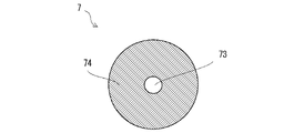
- FIG. 2 is a diagram showing an example of a cross section of a filter with a central hole.
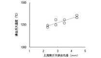
- FIG. 3 is a diagram showing simulation results of the relationship between the size of the gas discharge hole and the temperature of the discharged combustion gas.
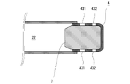
- FIG. 4 is an axial partial schematic sectional view showing an example of the gas generator according to the second embodiment.
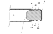
- FIG. 5 is an axial partial schematic sectional view showing an example of a gas generator according to a third embodiment.
- FIG. 6 is a partial side view showing an example of the gas generator according to the fourth embodiment.
- FIG. 7 is a partial schematic axial cross-sectional view showing a modification of the filter.
- FIG. 8 is a diagram schematically showing the flow of combustion gas within a filter according to a comparative example.
- FIG. 9 is a diagram schematically showing the flow of combustion gas within the filter according to the modified example described above.
- FIG. 1 is an axial schematic sectional view showing an example of the gas generator according to the present embodiment.
- the gas generator 1 can be used, for example, as a gas generator for inflating an airbag.
- the gas generator 1 of FIG. 1 includes a cylindrical housing 2, an ignition device 3 attached to one end side of the housing 2 in the axial direction, and a diffuser portion 4 formed on the other end side of the housing 2. As shown in FIG.
- the ignition device 3 is a device that ignites with an ignition current, and is the same as that used in known gas generators.
- the ignition device 3 has a metal cup body 31 that contains and seals an ignition charge, and a pair of current-carrying pins 32, 32 for receiving current supply from the outside. is fixed with a resin member 34 to the igniter holding portion 33 of the . Further, the igniter holding portion 33 of the ignition device 3 is attached to the opening portion of the housing 2 on one end side in the axial direction by, for example, all-around welding.
- the housing 2 is, for example, a cylindrical member having substantially uniform inner and outer diameters, and forms an outer shell container of the gas generator 1 .
- the material of the housing 2 is metal, for example.
- a cup-shaped partition wall 5 is arranged inside the housing 2 at a predetermined distance from the ignition device 3 .
- the partition wall 5 is, in other words, a bottomed cylindrical member, and the side portion includes a large diameter portion 51 with a large diameter and a small diameter portion 52 with a small diameter.
- the outer diameter of the large diameter portion 51 of the partition wall 5 is substantially the same as the inner diameter of the housing 2 . Therefore, the housing 2 can accommodate the partition wall 5 so that the bottom portion 53 is located on the diffuser portion 4 side.
- the housing 2 and the outer circumference of the large diameter portion 51 may be welded to each other, or engagement portions such as unevenness (see FIG. not shown).
- One or more through-holes 54 having a predetermined shape are formed in the bottom portion 53 of the partition wall 5 .
- the through holes 54 allow combustion products of the gas generating agent, which will be described later, to pass therethrough.
- a through-hole may also be provided in the side portion of the small-diameter portion 52 of the partition wall 5 .
- the partition wall 5 divides the internal space of the housing 2 into a first combustion chamber 21 (also referred to as an "enhancer chamber") formed between the ignition device 3 and the partition wall 5, the partition wall 5 and the diffuser portion. and a second combustion chamber 22 formed between.
- the side portion (large diameter portion 51 or small diameter portion 52) of the partition wall 5 is extended to such an extent that the partition wall 5 and the ignition device 3 are in contact with each other, and the partition wall 5 and the ignition device 3 form the first combustion chamber 21.
- the first combustion chamber 21 accommodates a first gas generating agent 61 (also referred to as "transfer charge” or “enhancer agent”).
- the second combustion chamber 22 accommodates a second gas generating agent 62 .
- the gas generating agents (first gas generating agent 61 and second gas generating agent 62) are formed by, for example, guanidine nitrate (41% by weight), basic copper nitrate (49% by weight), and binders and additives.
- guanidine nitrate 41% by weight
- basic copper nitrate 49% by weight
- binders and additives As for the shape of each gas generating agent, a single-hole cylindrical shape can be used.
- the gas generating agent is not limited to those mentioned above.
- the first gas generating agent 61 and the second gas generating agent 62 may be gas generating agents of the same kind, the same shape, and the same size, or may be gas generating agents of different kinds, different shapes, and different sizes. may
- the diffuser part 4 is a cup-shaped member attached so as to close the other end of the housing 2, and accommodates the filter 7 therein.
- the diffuser portion 4 has a bottomed cylindrical shape, and is arranged so that the open end faces the second combustion chamber 22 . That is, the diffuser portion 4 has a side wall 41 and a closed end 42 , and the open end of the side wall 41 opposite to the closed end 42 is connected to the housing 2 .
- the outer diameter of the side wall 41 is substantially the same as the inner diameter of the housing 2 , and a portion of the side wall 41 on the open end side is accommodated inside the housing 2 .
- the open end side of the side wall 41 may be fixed to the housing 2 by caulking, or the diffuser section 4 and the housing 2 may be welded.
- the diffuser portion 4 may be formed integrally with the housing 2 by, for example, drawing.
- one or more gas discharge holes 43 are formed in the side wall 41 of the diffuser section 4 .
- the gas discharge holes 43 include first gas discharge holes 431 (also called “first gas discharge hole group”) and second gas discharge holes 432 (also called “second gas discharge hole group”).
- first gas discharge holes 431 also called “first gas discharge hole group”
- second gas discharge holes 432 also called “second gas discharge hole group”
- the second gas discharge hole 432 may be provided in the closed end 42 instead of the side wall 41 .
- the opening area of each of the second gas discharge holes 432 is larger than that of the first gas discharge holes 431 .
- the number of the first gas discharge holes 431 and the number of the second gas discharge holes 432 are each one or more. , are formed at equal intervals in the circumferential direction of the diffuser portion 4, and the numbers of both are equal.
- the total opening area of the second gas discharge holes 432 is larger than the total opening area of the first gas discharge holes 431 .
- the “total opening area” means the total opening area of one or more gas discharge holes 43 (that is, the total opening area of the gas discharge holes included in the first gas discharge hole group and the second gas discharge hole group). total opening area of the gas discharge holes included in the hole group).
- the first gas discharge hole 431 and the second gas discharge hole 432 are provided at different distances from the second combustion chamber 22 . In the example of FIG. 1 , the second gas discharge hole 432 is farther from the second combustion chamber 22 than the first gas discharge hole 431 is.
- a housing space for housing the filter 7 is formed inside the cup-shaped diffuser portion 4 . At least part of the filter 7 is accommodated in the accommodation space of the diffuser section 4 .
- the filter 7 functions as a cooling unit that cools the combustion gas, and collects the combustion residue of the combustion gas to cool the combustion gas. filter.
- the filter 7 has a cylindrical shape, extends from the open end side of the diffuser portion 4 toward the closed end 42 side, and protrudes into the second combustion chamber 22 at the open end side. Moreover, the surface of the filter 7 is accommodated so as to face the gas discharge hole 43 of the diffuser portion 4 .
- the gas discharge hole 43 is provided in the closed end 42 of the diffuser portion 4
- the end surface of the filter 7 on the closed end 42 side faces the gas discharge hole 43 .
- the side surface of the filter 7 is in contact with the inner periphery of the side wall 41 of the diffuser portion 4 so that the combustion gas passes through the filter 7 .
- the filter 7 may be formed by putting flat-knitted metal wires into a molding die and compressing and molding them into a cylindrical shape.
- the filter 7 may be formed by winding a metal wire around a rod-shaped core material in a plurality of layers, and by crossing the wires to form a columnar shape having a mesh.
- the filter 7 may be a sheet-like perforated plate such as expanded metal, punching metal, metal lath, plain-woven wire mesh, tatami-woven wire mesh, etc. rolled up into a cylindrical shape.
- the filter 7 is a metal filter having a columnar solid cooling portion.
- the metal is stainless steel, iron, or the like, and may be plated or coated with copper, nickel, or the like.
- solid means that a metallic material is contained at a predetermined density in order to collect the combustion residue of the combustion gas and cool the combustion gas. Therefore, it is possible to use a filter whose density is almost evenly distributed over the entire area. There may be air gaps in any part of the filter, or there may be depressions formed in the end faces of the filter.
- the filter 7 protrudes from the diffuser portion 4 to the second combustion chamber 22 .
- An annular gap 23 is formed between the filter 7 and the housing 2 . Therefore, combustion gas flows into the filter 7 not only from the end face 71 of the filter 7 in the projecting direction toward the second combustion chamber 22 but also from the side of the gap 23 formed between the filter 7 and the housing 2 (from the tapered portion 72 described later). influx.
- the filter 7 protrude greatly toward the second combustion chamber 22 side the volume that can be used as the cooling section can be increased, and by widely dispersing the inflow points, a wide area of the filter 7 can be efficiently used as the cooling section. will be available as
- the filter 7 may be tapered so as to reduce its diameter in the projecting direction to the second combustion chamber 22 .
- the cross-sectional area of the cross section is reduced toward the end face 71, which is the end in the direction of the second combustion chamber 22, and around the end face 71 is formed obliquely with respect to the axial direction.
- a tapered portion 72 is provided.
- the tapered portion 72 angled with respect to the flow direction of the combustion gas facilitates the flow of the combustion gas into the filter 7 .
- the combustion gas flowing in from the side surface (tapered portion 72 in the example of FIG. 1) facing the gap 23 has a shorter distance through the inside of the filter 7 than the combustion gas flowing in from the end face 71.
- the surface area of the filter 7 facing the gap 23 (the surface area of the tapered portion 72 in the example of FIG. It is preferable to configure so as to be smaller than the surface area of the end surface 71 .
- the filter 7 may have, for example, a hole having a predetermined diameter or less in a cross section perpendicular to the axial direction and penetrating from one end face to the other end face along the axial direction.
- FIG. 2 is a diagram showing an example of a cross section of a filter with a central hole.
- the filter 7 has a through hole 73 along the axial direction, and a filter body 74 having an annular cross section around the through hole 73 .
- the through-holes 73 are formed, for example, by extracting the above-described core material after the filter 7 is formed.
- the filter body 74 functions as a solid cooling portion.
- 50 on the right side represents a reference value, in percentage, that the ratio of the cross-sectional area of the filter body 74 to the sum of the cross-sectional areas of the filter body 74 and the through hole 73 should exceed. That is, it is desirable that the cross-sectional area of the filter main body 74 is larger than the cross-sectional area of the through hole 73 .
- the tapered part is also the surface on which the gas enters, so the cross-sectional area of the filter body is the surface on which the gas flows. is the cross-sectional area of the portion indicated by the maximum diameter of the filter body 74 in .
- the reference value is more preferably "60", more preferably "75". That is, the cross-sectional area of the filter body 74 is more preferably greater than 60% of the sum of the cross-sectional areas of the filter body 74 and the through holes 73, and more preferably greater than 75%.
- an orifice plate 8 is provided in the second combustion chamber 22 on the diffuser portion 4 side and in the vicinity of the filter 7 .
- the orifice plate 8 is a disk-shaped member having one or more through holes 81 .
- the through-hole 81 is closed with a seal tape 82 and opens when the combustion gas causes the internal pressure of the second combustion chamber 22 to exceed a predetermined level.
- the combustion gas can be choke and the flow rate can be adjusted. Therefore, it is preferable.
- a canister made of a metal film such as aluminum or other structure may be used to airtightly hold the gas generating agent.
- a connector (not shown) is connected to a pair of current-carrying pins 32, 32 so that power can be supplied to the ignition device 3. .
- the ignition device 3 is actuated by the ignition current supplied to the pair of conducting pins 32 , 32 .
- the ignition device 3 burns the ignition powder in the cup body 31 and releases the combustion products to the outside of the cup body 31 .
- the first gas generating agent 61 is ignited by the flame and gas that are combustion products of the ignition charge.
- the first gas generating agent 61 generates combustion gas as a combustion product, and the combustion gas passes through the through hole 54 of the partition wall 5 and ignites the second gas generating agent 62 in the second combustion chamber 22 .
- the second gas generating agent 62 also produces combustion gas as a combustion product.
- the ratio between the amount of combustion gas discharged from the first gas discharge hole 431 and the amount of combustion gas discharged from the second gas discharge hole 432 per unit time is , according to the ratio of the area of the first gas discharge hole 431 and the area of the second gas discharge hole. Further, the temperature of the combustion gas discharged from the first gas discharge hole 431 and the temperature of the combustion gas discharged from the second gas discharge hole 432 are determined by the distance from the second combustion chamber 22 to each gas discharge hole (that is, , the distance that the combustion gas passes through the filter 7).
- the combustion gas discharged from the gas generator 1 has a temperature obtained by mixing the combustion gas discharged from the first gas discharge hole 431 and the combustion gas discharged from the second gas discharge hole 432, and the temperature can be adjusted by the size of the first gas discharge hole 431 and the size of the second gas discharge hole.
- FIG. 3 is a diagram showing simulation results of the relationship between the size of the gas discharge hole and the temperature of the discharged combustion gas.
- the horizontal axis in FIG. 3 indicates the diameter of the first gas discharge hole 431 on the upstream side.
- the diameter of the second gas discharge hole 432 on the downstream side was changed according to the diameter of the first gas discharge hole 431, and the total opening area of the first gas discharge hole 431 and the second gas discharge hole 432 was made equal.
- the vertical axis in FIG. 3 indicates the temperature of the exhausted combustion gas.
- the points plotted on the graph indicate the temperature when the temperature of the combustion gas discharged from the first gas discharge hole 431 and the temperature of the combustion gas discharged from the second gas discharge hole 432 are combined. As can be seen from FIG.
- the coefficient of determination R2 of the model formula indicated by the straight line in FIG. 3 was 0.7791.
- the second gas discharge hole 432 on the downstream side is enlarged, the amount of combustion gas passing through the portion of the filter 7 on the closed end 42 side of the diffuser portion 4 increases. Increases the ratio of passing long distances within That is, the filter 7 can sufficiently function as a cooling unit.
- the proportion of the combustion gas passing through a relatively short distance in the filter increases. Therefore, the temperature of combustion gas can also be raised.
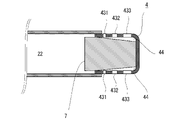
- FIG. 4 is an axial partial schematic sectional view showing an example of the gas generator according to the second embodiment.
- the diffuser section 4 is different from the embodiment of FIG.
- the same constituent elements as those of the first embodiment described above are denoted by corresponding reference numerals, or the illustration thereof is omitted.
- the area of the first gas discharge holes 431 closer to the second combustion chamber 22 is larger than the area of the second gas discharge holes 432 farther from the second combustion chamber 22 .
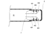
- FIG. 5 is an axial partial schematic sectional view showing an example of a gas generator according to a third embodiment. Also in this embodiment, only the diffuser section 4 is different from the embodiment of FIG. 1, and the same constituent elements as those of the above-described embodiment are denoted by corresponding reference numerals or omitted from the illustration.
- the diffuser portion 4 in FIG. 5 has three gas discharge holes 431 to 433 (three gas discharge hole groups) having different distances from the second combustion chamber 22 .
- the opening area increases in order from the upstream side toward the downstream side in the flow direction of the combustion gas.
- the number of gas discharge holes included in each gas discharge hole group shall be equal.
- the opening area may be made smaller in order from the upstream side toward the downstream side in the flow direction of the combustion gas.
- the distance from the second combustion chamber 22 and the opening area may be varied in three stages or more. Even in such an example, an arbitrary first gas discharge hole close to the second combustion chamber 22 and an arbitrary second gas discharge hole far from the second combustion chamber 22 have a predetermined total opening area.
- the temperature of the entire combustion gas discharged from the gas generator 1 can be adjusted.
- the combination of the gas discharge hole 431 and the gas discharge hole 432, the combination of the gas discharge hole 432 and the gas discharge hole 433, and the combination of the gas discharge hole 431 and the gas discharge hole 433 are the “second It corresponds to a combination of "1 gas discharge hole” and "second gas discharge hole”, and has a predetermined size relationship with respect to the total opening area.
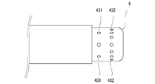
- FIG. 6 is a partial side view showing an example of the gas generator according to the fourth embodiment. Also in this embodiment, only the diffuser section 4 is different from the embodiment in FIG. 1, and the same constituent elements as those in the above-described embodiment are denoted by corresponding reference numerals or omitted from the illustration.
- the diffuser portion 4 in FIG. 6 has two gas discharge holes 431 and 432 (gas discharge hole group) that are different in distance from the second combustion chamber 22 .
- the size of each gas discharge hole is the same, and the number of first gas discharge holes 431 is smaller than the number of second gas discharge holes 432 .
- the number of gas discharge holes belonging to the first gas discharge hole group is smaller than the number of gas discharge holes belonging to the second gas discharge hole group.
- the total opening area of the first gas discharge holes 431 is smaller than the total opening area of the second gas discharge holes 432 . Note that the size relationship of the total opening area may be reversed. Even in such an example, the temperature of the combustion gas discharged from the gas generator 1 can be adjusted.
- FIG. 7 is a partial schematic axial cross-sectional view showing a modification of the filter. Also in this embodiment, the diffuser section 4 and the filter 7 are different from the embodiment of FIG. 1, and the same constituent elements as those of the above-described embodiment are denoted by corresponding reference numerals or omitted from the illustration.
- the closed end 42 side of the filter 7 is tapered, and the cross-sectional area of the cross section decreases toward the closed end. That is, in the example of FIG. 7, an annular gap 44 is formed between the diffuser portion 4 and the filter 7 .
- the side surface of the filter 7 is in contact with the inner periphery of the side wall 41 of the diffuser section 4 at least on the open end side so that the combustion gas passes through the filter 7 .
- the side surface of the filter 7 may be tapered on the open end side as well.
- the filter 7 of FIG. 7 is also housed in the housing space of the diffuser section 4 so as to face the gas discharge hole 43 .
- the filter 7 extends from the open end of the diffuser portion 4 to the closed end 42 and has a surface facing each of the gas discharge holes 43 . Accordingly, in this embodiment as well, the combustion gas is cooled according to the distance it has passed through the filter 7 and is discharged from the gas discharge hole 43 .
- FIG. 8 is a diagram schematically showing the flow of combustion gas within the filter according to the comparative example.
- Combustion gas introduced into the filter 7 tends to flow the shortest distance toward the gas discharge hole 43 . Therefore, when there is no space between the filter 7 and the diffuser section 4 as shown in FIG. In the example of FIG. 8, the portions indicated by triangles do not sufficiently perform the cooling function.
- FIG. 9 is a diagram schematically showing the flow of combustion gas within the filter according to the modified example described above.
- combustion gas smoothly flows out of the annular gap 44 from the filter 7 as shown in FIG. Therefore, compared to the comparative example of FIG. 8, the volume and weight of the filter 7 are smaller, but the area where the cooling function is not sufficiently performed is reduced because the flow of combustion gas is less likely to occur.
- the filter 7 when the filter 7 is formed of a wire, when the combustion gas passes through the filter 7 and is discharged, the wire frays on the outer circumference of the filter 7, and fragments of the wire are discharged from the gas discharge hole 43. may be In particular, when most of the side surfaces of the filter 7 are in contact with the side walls 41 of the diffuser portion 4 as shown in FIG. Partial fraying of the wire tends to occur. On the other hand, when an annular gap 44 is formed between the diffuser portion 4 and the filter 7 as shown in FIG. 7, the portion through which the combustion gas flows can be dispersed, and the occurrence of fraying can be reduced. can.
- the filter 7 is arranged without a gap between it and the side wall 41 of the diffuser portion 4, the volume of the filter 7 is increased, and the combustion gas cooling effect can be enhanced.
- each gas discharge hole 43 monotonously increases or decreases from the upstream side to the downstream side in the direction of combustion gas flow, or Although an example in which the number of gas discharge holes 43 monotonously increases or decreases from the upstream side to the downstream side has been shown, the present invention is not limited to such an example. That is, in a gas generator in which gas flows in the axial direction of the filter, the degree of cooling is adjusted by making a difference between the amount of gas discharged after flowing only on the upstream side of the filter and the amount of gas discharged after flowing to the downstream side of the filter.
- the opening ratio of the gas discharge holes with respect to the surface area of the diffuser portion may be different between the upstream side and the downstream side in the flow direction of the combustion gas. Also in this case, it can be said that the total opening area of the first gas discharge holes provided on the upstream side is different from the total opening area of the second gas discharge holes provided on the downstream side.
- the shape of the gas discharge port 43 is not limited to a circle. , may have a shape other than an ellipse.
- gas generator 2 housing 21: first combustion chamber 22: second combustion chamber 23: gap 3: ignition device 31: cup body 32: conducting pin 33: igniter holding portion 34: resin member 4: diffuser portion 41 : Side wall 42 : Closed end 43 : Gas discharge hole 431 : First gas discharge hole 432 : Second gas discharge hole 44 : Gap 5 : Partition wall 51 : Large diameter portion 52 : Small diameter portion 53 : Bottom portion 54 : Through hole 61 : Third 1 gas generating agent 62: second gas generating agent 7: filter 71: end surface 72: tapered portion 73: through hole 8: orifice plate 81: through hole 82: sealing tape
Landscapes
- Engineering & Computer Science (AREA)
- Physics & Mathematics (AREA)
- Fluid Mechanics (AREA)
- Mechanical Engineering (AREA)
- General Engineering & Computer Science (AREA)
- Air Bags (AREA)
Abstract
Description
図1は、本実施形態に係るガス発生器の一例を示す軸方向の概略断面図である。ガス発生器1は、例えばエアバッグを膨張させるためのガス発生装置として利用できる。図1のガス発生器1は、筒状のハウジング2と、ハウジング2の軸方向の一端側に取り付けられる点火装置3と、ハウジング2の他端側に形成されるディフューザ部4とを備える。
(フィルタ本体74の断面積/(フィルタ本体74の断面積+貫通孔73の断面積))×100>50
右辺の「50」は、フィルタ本体74及び貫通孔73の断面積の和に対する、フィルタ本体74の断面積の割合が超えるべき基準値を百分率で表すものといえる。すなわち、フィルタ本体74の断面積が貫通孔73の断面積よりも大きいことが望ましい。なおフィルタの端面のうちガスが流れ込む側がテーパになっている場合(例えば図1のような形状)、テーパ部分もガスが入り込む面になることから、フィルタ本体の断面積は、ガスが流入する面におけるフィルタ本体74の最大径で示される部分の断面積とする。また、上記基準値は、より好ましくは「60」であり、さらに好ましくは「75」である。すなわち、フィルタ本体74の断面積は、フィルタ本体74及び貫通孔73の断面積の和のうち60%を超える大きさであることがより好ましく、75%を超える大きさであることがさらに好ましい。
ガス発生器1が例えば自動車のエアバッグ等に組み付けられた状態では、コネクタ(図示せず)が一対の通電ピン32、32と接続されており、点火装置3に対して給電可能になっている。この状態で、自動車等に搭載されたセンサ(図示せず)が衝撃を感知すると、点火装置3は、一対の通電ピン32、32に供給される着火電流により作動する。点火装置3は、カップ体31内の点火薬を燃焼させ、その燃焼生成物をカップ体31の外部に放出させる。また、点火薬の燃焼生成物である火炎やガスにより、第1ガス発生剤61が着火する。また、第1ガス発生剤61は、燃焼生成物として燃焼ガスを生成し、燃焼ガスは隔壁5の貫通孔54を通過して第2燃焼室22の第2ガス発生剤62を着火させる。また、第2ガス発生剤62も、燃焼生成物として燃焼ガスを生成する。第2燃焼室22の燃焼ガスの圧力によりオリフィスプレート8のシールテープ82が開裂すると、燃焼ガスは貫通孔81及びフィルタ7を通過してろ過および冷却され、ディフューザ部4のガス排出孔43から排出される。
ガス発生器1の内圧が十分に高い場合、第1ガス排出孔431から排出される燃焼ガスの量と、第2ガス排出孔432から排出される燃焼ガスの単位時間当たりの量との比は、第1ガス排出孔431の面積と、第2ガス排出孔の面積との比に応じたものになる。また、第1ガス排出孔431から排出される燃焼ガスの温度と、第2ガス排出孔432から排出される燃焼ガスの温度とは、第2燃焼室22から各ガス排出孔までの距離(すなわち、燃焼ガスがフィルタ7を通過する距離)に応じて冷却されたものになる。したがって、ガス発生器1から排出される燃焼ガスは、第1ガス排出孔431から排出された燃焼ガスと第2ガス排出孔432から排出された燃焼ガスとを混合した温度を有し、その温度は第1ガス排出孔431の大きさ及び第2ガス排出孔の大きさによって調整することができる。
図4は、第2の実施形態に係るガス発生器の一例を示す軸方向の部分的な概略断面図である。本実施形態においては、ディフューザ部4が図1の実施例と異なっている。そして上述した第1の実施形態と同一の構成要素には対応する符号を付し、又は図示を省略する。
図5は、第3の実施形態に係るガス発生器の一例を示す軸方向の部分的な概略断面図である。本実施形態においても、ディフューザ部4のみが図1の実施例と異なっており、上述した実施形態と同一の構成要素には対応する符号を付し、又は図示を省略する。
図6は、第4の実施形態に係るガス発生器の一例を示す部分的な側面図である。本実施形態においてもディフューザ部4のみが図1の実施例と異なっており、上述した実施形態と同一の構成要素には対応する符号を付し、又は図示を省略する。
図7は、フィルタの変形例を示す軸方向の部分的な概略断面図である。本実施形態においてもディフューザ部4とフィルタ7が図1の実施例と異なっており、上述した実施形態と同一の構成要素には対応する符号を付し、又は図示を省略する。
以上、本開示に係るガス発生装置の実施形態について説明したが、本明細書に開示された各々の態様は、本明細書に開示された他の特徴と組み合わせることができる。また、ガス発生器1は、エアバッグ以外の装置に組み込んでもよい。
2:ハウジング
21:第1燃焼室
22:第2燃焼室
23:間隙
3:点火装置
31:カップ体
32:通電ピン
33:点火器保持部
34:樹脂部材
4:ディフューザ部
41:側壁
42:閉塞端
43:ガス排出孔
431:第1ガス排出孔
432:第2ガス排出孔
44:間隙
5:隔壁
51:大径部
52:小径部
53:底部
54:貫通孔
61:第1ガス発生剤
62:第2ガス発生剤
7:フィルタ
71:端面
72:テーパ部
73:貫通孔
8:オリフィスプレート
81:貫通孔
82:シールテープ
Claims (9)
- 外殻容器を形成するハウジングと、
前記ハウジングの一端側に取り付けられた点火装置と、
前記ハウジングの内部に形成され、ガス発生剤を収容する燃焼室と、
前記ハウジングにおける他端側に形成されるカップ状のディフューザ部であって、一方の端部に形成された閉塞端と、前記閉塞端の反対側に形成された開放端と、前記閉塞端および前記開放端との間に位置する側壁とを含み、前記開放端が前記燃焼室に臨むように配置されると共に内側にフィルタを収容する収容空間が形成され、複数のガス排出孔を有するディフューザ部と、
前記複数のガス排出孔と対向するように少なくとも一部が前記収容空間に収容されたフィルタであって、前記ディフューザ部における前記開放端の側から前記閉塞端の側に向かって延在すると共に前記ガス発生剤の燃焼ガスを冷却する中実状の冷却部を有する、フィルタと、
を備え、
前記複数のガス排出孔は、前記燃焼室からの距離が相対的に近い1又は複数の第1ガス排出孔と、前記燃焼室からの距離が前記第1又は複数の第1ガス排出孔よりも相対的に遠い1又は複数の第2ガス排出孔と、を含み、前記1又は複数の第1ガス排出孔の総開口面積と前記1又は複数の第2ガス排出孔の総開口面積とが異なっている、
ガス発生器。 - 前記1又は複数の第1ガス排出孔及び前記1又は複数の第2ガス排出孔は、前記ディフューザ部の前記側壁に設けられ、
前記フィルタは、前記ディフューザ部の前記側壁との間に間隙なく配置される
請求項1に記載のガス発生器。 - 前記1又は複数の第1ガス排出孔及び前記1又は複数の第2ガス排出孔は、前記ディフューザ部の前記側壁に設けられ、
前記フィルタには、前記ディフューザ部における前記開放端の側から前記閉塞端の側に向かって縮径するテーパが形成され、前記フィルタと前記ディフューザ部の前記側壁との間に環状の間隙を有する
請求項1に記載のガス発生器。 - 前記1又は複数の第1ガス排出孔の総開口面積よりも、前記1又は複数の第2ガス排出孔の総開口面積の方が大きい
請求項1から3のいずれか一項に記載のガス発生器。 - 前記1又は複数の第1ガス排出孔及び前記複数の第2ガス排出孔のそれぞれは、径が同一であり、前記1又は複数の第1ガス排出孔の数よりも、前記複数の第2ガス排出孔の数の方が多い
請求項4に記載のガス発生器。 - 前記1又は複数の第1ガス排出孔の数は、前記1又は複数の第2ガス排出孔の数と同一であり、前記1又は複数の第1ガス排出孔のそれぞれの開口面積よりも、前記1又は複数の第2ガス排出孔のそれぞれの開口面積の方が大きい
請求項4に記載のガス発生器。 - 前記フィルタは、前記ディフューザ部における前記開放端から、前記ハウジングの内部に形成された前記燃焼室に向けて突出すると共に、前記フィルタと前記ハウジングとの間に環状の間隙を有する
請求項1から6のいずれか一項に記載のガス発生器。 - 前記フィルタは、金属製の線材又は多孔板によって形成される
請求項1から7のいずれか一項に記載のガス発生器。 - 前記フィルタは、前記ディフューザ部における前記開放端の側から前記閉塞端の側に向かって延在する貫通孔を有する
請求項1から8のいずれか一項に記載のガス発生器。
Priority Applications (3)
| Application Number | Priority Date | Filing Date | Title |
|---|---|---|---|
| CN202180097586.6A CN117203096A (zh) | 2021-04-30 | 2021-12-28 | 气体发生器 |
| EP21939396.4A EP4331923A4 (en) | 2021-04-30 | 2021-12-28 | GAS GENERATOR |
| US18/384,999 US12546573B2 (en) | 2021-04-30 | 2023-10-30 | Gas generator |
Applications Claiming Priority (2)
| Application Number | Priority Date | Filing Date | Title |
|---|---|---|---|
| JP2021-077911 | 2021-04-30 | ||
| JP2021077911A JP7641169B2 (ja) | 2021-04-30 | 2021-04-30 | ガス発生器 |
Related Child Applications (1)
| Application Number | Title | Priority Date | Filing Date |
|---|---|---|---|
| US18/384,999 Continuation US12546573B2 (en) | 2021-04-30 | 2023-10-30 | Gas generator |
Publications (1)
| Publication Number | Publication Date |
|---|---|
| WO2022230242A1 true WO2022230242A1 (ja) | 2022-11-03 |
Family
ID=83846825
Family Applications (1)
| Application Number | Title | Priority Date | Filing Date |
|---|---|---|---|
| PCT/JP2021/048794 Ceased WO2022230242A1 (ja) | 2021-04-30 | 2021-12-28 | ガス発生器 |
Country Status (5)
| Country | Link |
|---|---|
| US (1) | US12546573B2 (ja) |
| EP (1) | EP4331923A4 (ja) |
| JP (1) | JP7641169B2 (ja) |
| CN (1) | CN117203096A (ja) |
| WO (1) | WO2022230242A1 (ja) |
Cited By (1)
| Publication number | Priority date | Publication date | Assignee | Title |
|---|---|---|---|---|
| US20240060753A1 (en) * | 2021-04-30 | 2024-02-22 | Daicel Corporation | Gas generator |
Families Citing this family (1)
| Publication number | Priority date | Publication date | Assignee | Title |
|---|---|---|---|---|
| JP2025142850A (ja) * | 2024-03-18 | 2025-10-01 | 日本化薬株式会社 | ガス発生器およびその製造方法 |
Citations (8)
| Publication number | Priority date | Publication date | Assignee | Title |
|---|---|---|---|---|
| JPH0986331A (ja) * | 1995-09-22 | 1997-03-31 | Nippon Seiko Kk | エアバッグ装置 |
| JP3044475U (ja) * | 1996-06-10 | 1997-12-22 | オートリブ エーエスピー,インコーポレイティド | 方向性を有する圧縮ガス式インフレータ |
| JP2000118347A (ja) * | 1998-10-12 | 2000-04-25 | Toyoda Gosei Co Ltd | エアバッグ装置 |
| JP2002539007A (ja) * | 1999-01-27 | 2002-11-19 | コンテック ヘミーアンラーゲン ゲーエムベーハー | ガスジェネレータ |
| JP2003034221A (ja) * | 2001-07-23 | 2003-02-04 | Toyota Motor Corp | エアバッグ装置のディフューザ構造 |
| JP2006522715A (ja) * | 2003-04-08 | 2006-10-05 | オートリブ エーエスピー,インコーポレイティド | 自動車のエアバッグシステム用火薬式インフレータ |
| JP2010260387A (ja) * | 2009-04-30 | 2010-11-18 | Nippon Kayaku Co Ltd | ガス発生器 |
| JP2016022929A (ja) | 2014-07-24 | 2016-02-08 | 日本化薬株式会社 | ガス発生器 |
Family Cites Families (14)
| Publication number | Priority date | Publication date | Assignee | Title |
|---|---|---|---|---|
| US5269561A (en) * | 1992-07-06 | 1993-12-14 | Morton International, Inc. | Vented gas passenger side air bag inflator |
| DE202005017267U1 (de) * | 2005-05-18 | 2006-03-09 | Trw Automotive Gmbh | Gassackmodul |
| DE202005008847U1 (de) * | 2005-06-03 | 2005-10-06 | Autoliv Development Ab | Gasgeneratoreinheit |
| US7722078B2 (en) * | 2006-12-18 | 2010-05-25 | Daicel Chemical Industries, Ltd. | Gas generator and restraining device using same |
| KR20120023623A (ko) * | 2009-04-30 | 2012-03-13 | 닛뽄 가야쿠 가부시키가이샤 | 가스 발생기 |
| JP5399935B2 (ja) * | 2010-02-03 | 2014-01-29 | 株式会社ダイセル | ガス発生器 |
| JP6219132B2 (ja) * | 2013-11-07 | 2017-10-25 | 株式会社ダイセル | ガス発生器 |
| JP6619293B2 (ja) * | 2016-05-23 | 2019-12-11 | 株式会社ダイセル | ガス発生器 |
| DE102019100262A1 (de) | 2018-10-02 | 2020-04-02 | Trw Automotive Gmbh | Baugruppe aus einem Diffusor und einem Gasgenerator, Gassackmodul und Verfahren zur Montage einer Baugruppe |
| DE102019124202A1 (de) * | 2019-09-10 | 2021-03-11 | Zf Automotive Germany Gmbh | Gassackmodul und Fahrzeugsitz und Fahrzeuginsassen-Schutzsystem |
| JP7641169B2 (ja) * | 2021-04-30 | 2025-03-06 | 株式会社ダイセル | ガス発生器 |
| JP7702305B2 (ja) * | 2021-08-23 | 2025-07-03 | 株式会社ダイセル | エアバッグ装置及びガス発生装置 |
| JP7745448B2 (ja) * | 2021-12-03 | 2025-09-29 | 株式会社ダイセル | ガス発生器及びエアバッグ装置 |
| JP7805859B2 (ja) * | 2022-05-16 | 2026-01-26 | 株式会社ダイセル | ガス発生器 |
-
2021
- 2021-04-30 JP JP2021077911A patent/JP7641169B2/ja active Active
- 2021-12-28 WO PCT/JP2021/048794 patent/WO2022230242A1/ja not_active Ceased
- 2021-12-28 EP EP21939396.4A patent/EP4331923A4/en active Pending
- 2021-12-28 CN CN202180097586.6A patent/CN117203096A/zh active Pending
-
2023
- 2023-10-30 US US18/384,999 patent/US12546573B2/en active Active
Patent Citations (8)
| Publication number | Priority date | Publication date | Assignee | Title |
|---|---|---|---|---|
| JPH0986331A (ja) * | 1995-09-22 | 1997-03-31 | Nippon Seiko Kk | エアバッグ装置 |
| JP3044475U (ja) * | 1996-06-10 | 1997-12-22 | オートリブ エーエスピー,インコーポレイティド | 方向性を有する圧縮ガス式インフレータ |
| JP2000118347A (ja) * | 1998-10-12 | 2000-04-25 | Toyoda Gosei Co Ltd | エアバッグ装置 |
| JP2002539007A (ja) * | 1999-01-27 | 2002-11-19 | コンテック ヘミーアンラーゲン ゲーエムベーハー | ガスジェネレータ |
| JP2003034221A (ja) * | 2001-07-23 | 2003-02-04 | Toyota Motor Corp | エアバッグ装置のディフューザ構造 |
| JP2006522715A (ja) * | 2003-04-08 | 2006-10-05 | オートリブ エーエスピー,インコーポレイティド | 自動車のエアバッグシステム用火薬式インフレータ |
| JP2010260387A (ja) * | 2009-04-30 | 2010-11-18 | Nippon Kayaku Co Ltd | ガス発生器 |
| JP2016022929A (ja) | 2014-07-24 | 2016-02-08 | 日本化薬株式会社 | ガス発生器 |
Non-Patent Citations (1)
| Title |
|---|
| See also references of EP4331923A4 |
Cited By (2)
| Publication number | Priority date | Publication date | Assignee | Title |
|---|---|---|---|---|
| US20240060753A1 (en) * | 2021-04-30 | 2024-02-22 | Daicel Corporation | Gas generator |
| US12546573B2 (en) * | 2021-04-30 | 2026-02-10 | Daicel Corporation | Gas generator |
Also Published As
| Publication number | Publication date |
|---|---|
| EP4331923A1 (en) | 2024-03-06 |
| US12546573B2 (en) | 2026-02-10 |
| CN117203096A (zh) | 2023-12-08 |
| EP4331923A4 (en) | 2025-03-26 |
| JP7641169B2 (ja) | 2025-03-06 |
| JP2022171327A (ja) | 2022-11-11 |
| US20240060753A1 (en) | 2024-02-22 |
Similar Documents
| Publication | Publication Date | Title |
|---|---|---|
| US12546573B2 (en) | Gas generator | |
| CN102753401B (zh) | 气体发生器及其装配方法 | |
| JP5324930B2 (ja) | 車両の人員拘束装置用ガス発生器 | |
| US5829785A (en) | Internal structure for a two-walled inflator | |
| US9950688B2 (en) | Gas generator | |
| US10870409B2 (en) | Gas generator | |
| US12612007B2 (en) | Gas generator | |
| CN109257930B (zh) | 气体发生器 | |
| JP2009500223A (ja) | ガス生成装置 | |
| US10046727B2 (en) | Gas generator | |
| JP6633985B2 (ja) | ガス発生器 | |
| CN110139781A (zh) | 充气机 | |
| JP2017007456A (ja) | ガス発生器 | |
| KR102113570B1 (ko) | 가스 발생기 | |
| US10723308B2 (en) | Gas generator | |
| CN108349457A (zh) | 气体发生器 | |
| JP2016196263A (ja) | ガス発生器 | |
| CN110770089B (zh) | 气体发生器 | |
| US20240239723A1 (en) | Gas generator and gas discharge method | |
| US11040692B2 (en) | Multi-vent passenger side airbag inflator | |
| WO2004052693A1 (ja) | エアバッグ用ガス発生器 | |
| JP2020040453A (ja) | ガス発生器及びガス発生器用のクッション部材 | |
| CN117396371A (zh) | 气体发生器和气体排出方法 | |
| JP2022179278A (ja) | ガス発生器及びガス排出方法 | |
| JP6422327B2 (ja) | ガス発生器 |
Legal Events
| Date | Code | Title | Description |
|---|---|---|---|
| 121 | Ep: the epo has been informed by wipo that ep was designated in this application |
Ref document number: 21939396 Country of ref document: EP Kind code of ref document: A1 |
|
| WWE | Wipo information: entry into national phase |
Ref document number: 202180097586.6 Country of ref document: CN |
|
| WWE | Wipo information: entry into national phase |
Ref document number: 202317077472 Country of ref document: IN |
|
| WWE | Wipo information: entry into national phase |
Ref document number: 2021939396 Country of ref document: EP |
|
| ENP | Entry into the national phase |
Ref document number: 2021939396 Country of ref document: EP Effective date: 20231130 |
|
| NENP | Non-entry into the national phase |
Ref country code: DE |