WO2022244352A1 - 検体容器及び自動分析装置 - Google Patents
検体容器及び自動分析装置 Download PDFInfo
- Publication number
- WO2022244352A1 WO2022244352A1 PCT/JP2022/006602 JP2022006602W WO2022244352A1 WO 2022244352 A1 WO2022244352 A1 WO 2022244352A1 JP 2022006602 W JP2022006602 W JP 2022006602W WO 2022244352 A1 WO2022244352 A1 WO 2022244352A1
- Authority
- WO
- WIPO (PCT)
- Prior art keywords
- sample
- specimen
- test tube
- container
- specimen container
- Prior art date
- Legal status (The legal status is an assumption and is not a legal conclusion. Google has not performed a legal analysis and makes no representation as to the accuracy of the status listed.)
- Ceased
Links
Images


Classifications
-
- G—PHYSICS
- G01—MEASURING; TESTING
- G01N—INVESTIGATING OR ANALYSING MATERIALS BY DETERMINING THEIR CHEMICAL OR PHYSICAL PROPERTIES
- G01N35/00—Automatic analysis not limited to methods or materials provided for in any single one of groups G01N1/00 - G01N33/00; Handling materials therefor
- G01N35/00584—Control arrangements for automatic analysers
- G01N35/00594—Quality control, including calibration or testing of components of the analyser
- G01N35/00613—Quality control
- G01N35/00623—Quality control of instruments
-
- G—PHYSICS
- G01—MEASURING; TESTING
- G01N—INVESTIGATING OR ANALYSING MATERIALS BY DETERMINING THEIR CHEMICAL OR PHYSICAL PROPERTIES
- G01N35/00—Automatic analysis not limited to methods or materials provided for in any single one of groups G01N1/00 - G01N33/00; Handling materials therefor
- G01N35/10—Devices for transferring samples or any liquids to, in, or from, the analysis apparatus, e.g. suction devices, injection devices
- G01N35/1009—Characterised by arrangements for controlling the aspiration or dispense of liquids
- G01N35/1011—Control of the position or alignment of the transfer device
-
- B—PERFORMING OPERATIONS; TRANSPORTING
- B01—PHYSICAL OR CHEMICAL PROCESSES OR APPARATUS IN GENERAL
- B01L—CHEMICAL OR PHYSICAL LABORATORY APPARATUS FOR GENERAL USE
- B01L3/00—Containers or dishes for laboratory use, e.g. laboratory glassware; Droppers
- B01L3/50—Containers for the purpose of retaining a material to be analysed, e.g. test tubes
- B01L3/508—Rigid containers without fluid transport within
- B01L3/5082—Test tubes per se
-
- B—PERFORMING OPERATIONS; TRANSPORTING
- B01—PHYSICAL OR CHEMICAL PROCESSES OR APPARATUS IN GENERAL
- B01L—CHEMICAL OR PHYSICAL LABORATORY APPARATUS FOR GENERAL USE
- B01L3/00—Containers or dishes for laboratory use, e.g. laboratory glassware; Droppers
- B01L3/50—Containers for the purpose of retaining a material to be analysed, e.g. test tubes
- B01L3/508—Rigid containers without fluid transport within
- B01L3/5085—Rigid containers without fluid transport within for multiple samples, e.g. microtitration plates
- B01L3/50853—Rigid containers without fluid transport within for multiple samples, e.g. microtitration plates with covers or lids
-
- G—PHYSICS
- G01—MEASURING; TESTING
- G01N—INVESTIGATING OR ANALYSING MATERIALS BY DETERMINING THEIR CHEMICAL OR PHYSICAL PROPERTIES
- G01N1/00—Sampling; Preparing specimens for investigation
-
- G—PHYSICS
- G01—MEASURING; TESTING
- G01N—INVESTIGATING OR ANALYSING MATERIALS BY DETERMINING THEIR CHEMICAL OR PHYSICAL PROPERTIES
- G01N33/00—Investigating or analysing materials by specific methods not covered by groups G01N1/00 - G01N31/00
- G01N33/48—Biological material, e.g. blood, urine; Haemocytometers
- G01N33/483—Physical analysis of biological material
- G01N33/487—Physical analysis of biological material of liquid biological material
- G01N33/49—Blood
-
- G—PHYSICS
- G01—MEASURING; TESTING
- G01N—INVESTIGATING OR ANALYSING MATERIALS BY DETERMINING THEIR CHEMICAL OR PHYSICAL PROPERTIES
- G01N33/00—Investigating or analysing materials by specific methods not covered by groups G01N1/00 - G01N31/00
- G01N33/48—Biological material, e.g. blood, urine; Haemocytometers
- G01N33/483—Physical analysis of biological material
- G01N33/487—Physical analysis of biological material of liquid biological material
- G01N33/493—Physical analysis of biological material of liquid biological material urine
-
- G—PHYSICS
- G01—MEASURING; TESTING
- G01N—INVESTIGATING OR ANALYSING MATERIALS BY DETERMINING THEIR CHEMICAL OR PHYSICAL PROPERTIES
- G01N35/00—Automatic analysis not limited to methods or materials provided for in any single one of groups G01N1/00 - G01N33/00; Handling materials therefor
- G01N35/02—Automatic analysis not limited to methods or materials provided for in any single one of groups G01N1/00 - G01N33/00; Handling materials therefor using a plurality of sample containers moved by a conveyor system past one or more treatment or analysis stations
- G01N35/04—Details of the conveyor system
-
- G—PHYSICS
- G01—MEASURING; TESTING
- G01N—INVESTIGATING OR ANALYSING MATERIALS BY DETERMINING THEIR CHEMICAL OR PHYSICAL PROPERTIES
- G01N35/00—Automatic analysis not limited to methods or materials provided for in any single one of groups G01N1/00 - G01N33/00; Handling materials therefor
- G01N35/10—Devices for transferring samples or any liquids to, in, or from, the analysis apparatus, e.g. suction devices, injection devices
- G01N35/1065—Multiple transfer devices
-
- B—PERFORMING OPERATIONS; TRANSPORTING
- B01—PHYSICAL OR CHEMICAL PROCESSES OR APPARATUS IN GENERAL
- B01L—CHEMICAL OR PHYSICAL LABORATORY APPARATUS FOR GENERAL USE
- B01L2200/00—Solutions for specific problems relating to chemical or physical laboratory apparatus
- B01L2200/02—Adapting objects or devices to another
- B01L2200/023—Adapting objects or devices to another adapted for different sizes of tubes, tips or container
-
- B—PERFORMING OPERATIONS; TRANSPORTING
- B01—PHYSICAL OR CHEMICAL PROCESSES OR APPARATUS IN GENERAL
- B01L—CHEMICAL OR PHYSICAL LABORATORY APPARATUS FOR GENERAL USE
- B01L2300/00—Additional constructional details
- B01L2300/08—Geometry, shape and general structure
- B01L2300/0832—Geometry, shape and general structure cylindrical, tube shaped
-
- B—PERFORMING OPERATIONS; TRANSPORTING
- B01—PHYSICAL OR CHEMICAL PROCESSES OR APPARATUS IN GENERAL
- B01L—CHEMICAL OR PHYSICAL LABORATORY APPARATUS FOR GENERAL USE
- B01L2300/00—Additional constructional details
- B01L2300/08—Geometry, shape and general structure
- B01L2300/0848—Specific forms of parts of containers
- B01L2300/0851—Bottom walls
-
- B—PERFORMING OPERATIONS; TRANSPORTING
- B01—PHYSICAL OR CHEMICAL PROCESSES OR APPARATUS IN GENERAL
- B01L—CHEMICAL OR PHYSICAL LABORATORY APPARATUS FOR GENERAL USE
- B01L2300/00—Additional constructional details
- B01L2300/08—Geometry, shape and general structure
- B01L2300/0848—Specific forms of parts of containers
- B01L2300/0858—Side walls
-
- G—PHYSICS
- G01—MEASURING; TESTING
- G01N—INVESTIGATING OR ANALYSING MATERIALS BY DETERMINING THEIR CHEMICAL OR PHYSICAL PROPERTIES
- G01N35/00—Automatic analysis not limited to methods or materials provided for in any single one of groups G01N1/00 - G01N33/00; Handling materials therefor
- G01N35/02—Automatic analysis not limited to methods or materials provided for in any single one of groups G01N1/00 - G01N33/00; Handling materials therefor using a plurality of sample containers moved by a conveyor system past one or more treatment or analysis stations
- G01N35/04—Details of the conveyor system
- G01N2035/0401—Sample carriers, cuvettes or reaction vessels
- G01N2035/0406—Individual bottles or tubes
-
- G—PHYSICS
- G01—MEASURING; TESTING
- G01N—INVESTIGATING OR ANALYSING MATERIALS BY DETERMINING THEIR CHEMICAL OR PHYSICAL PROPERTIES
- G01N35/00—Automatic analysis not limited to methods or materials provided for in any single one of groups G01N1/00 - G01N33/00; Handling materials therefor
- G01N35/02—Automatic analysis not limited to methods or materials provided for in any single one of groups G01N1/00 - G01N33/00; Handling materials therefor using a plurality of sample containers moved by a conveyor system past one or more treatment or analysis stations
- G01N35/04—Details of the conveyor system
- G01N2035/0401—Sample carriers, cuvettes or reaction vessels
- G01N2035/0412—Block or rack elements with a single row of samples
-
- G—PHYSICS
- G01—MEASURING; TESTING
- G01N—INVESTIGATING OR ANALYSING MATERIALS BY DETERMINING THEIR CHEMICAL OR PHYSICAL PROPERTIES
- G01N35/00—Automatic analysis not limited to methods or materials provided for in any single one of groups G01N1/00 - G01N33/00; Handling materials therefor
- G01N35/02—Automatic analysis not limited to methods or materials provided for in any single one of groups G01N1/00 - G01N33/00; Handling materials therefor using a plurality of sample containers moved by a conveyor system past one or more treatment or analysis stations
- G01N35/025—Automatic analysis not limited to methods or materials provided for in any single one of groups G01N1/00 - G01N33/00; Handling materials therefor using a plurality of sample containers moved by a conveyor system past one or more treatment or analysis stations having a carousel or turntable for reaction cells or cuvettes
Definitions
- the present invention relates to a sample container containing a sample to be analyzed by an automatic analyzer.
- An automatic analyzer is a device that automatically qualitatively or quantitatively analyzes specific components contained in specimens such as blood and urine.
- the sample may be stored in a sample container placed on the test tube used to collect the sample.
- a specimen container has a smaller dead volume, which is the limit of aspiration, compared to a test tube, and is suitable for handling a very small amount of specimen. It should be noted that there are multiple types of test tube diameters, and it takes time and effort to prepare sample containers according to the type of test tube.
- Patent Document 1 discloses a specimen container that can accommodate multiple types of test tubes with different diameters. That is, in a sample container having a storage portion that stores a sample and is inserted into a test tube, and a flange portion that is provided at the upper end of the storage portion and placed on the open end of the test tube, a concentric circular shape corresponding to the type of test tube is used. is provided on the lower surface of the flange portion.
- Patent Document 1 does not give sufficient consideration to variations in the diameter of test tubes.
- the outer diameter of a test tube varies from ⁇ 10 mm to ⁇ 13 mm for a specification of ⁇ 13 mm, and the inner diameter of the test tube also varies accordingly. Horizontal misalignment may occur. If the positional displacement of the sample container with respect to the test tube is large, the sample dispensing probe that dispenses the sample from the sample container may get caught on the inner wall of the sample container and may not be able to descend to a predetermined height, degrading sample dispensing accuracy. be.
- an object of the present invention is to provide a sample container that can dispense a sample with high accuracy even if the diameter of the test tube varies.
- the present invention provides a specimen having a container for containing a sample and inserted into a test tube, and a flange provided at the upper end of the container for placing on the open end of the test tube.
- the container has a cylindrical body and a cup-shaped bottom connected to the body. Characterized by having a slope of less than 20 degrees.
- FIG. 5 is a diagram for explaining an operation for correcting positional deviation of a sample container
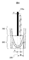
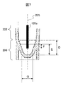
- FIG. 4 is a diagram for explaining the shape of the bottom of a specimen container
- FIG. 4 is a diagram for explaining the shape of the bottom of a specimen container
- An automatic analyzer is an apparatus that analyzes a specimen using a reaction liquid obtained by reacting a specimen such as blood or urine with a reagent.
- the automatic analyzer includes a sample transport section 102 , a reagent disk 104 , a sample dispensing section 105 , a reagent dispensing section 106 , a reaction disk 107 , a measurement section 108 and a control section 113 . Each part will be described below.
- the sample transport unit 102 stores samples such as blood and urine, and transports the test tubes 101 placed on the sample rack 109 to a position accessible by the sample dispensing unit 105 .
- the specimen dispensing unit 105 dispenses the specimen from the test tube 101 transported by the specimen transporting part 102 to the reaction container 111 arranged on the reaction disk 107 .
- a sample pipetting probe 105a included in the sample pipetting unit 105 is used for pipetting the sample. That is, after the sample pipetting probe 105a is inserted into the test tube 101 and aspirates the sample, it moves to the reaction container 111 and discharges the sample. If the amount of sample is very small, the sample is transferred to a sample container 200, which will be described later with reference to FIG.
- the sample container 200 is placed on the test tube 101 and used, and has a smaller dead volume, which is the suction limit amount, compared to the test tube 101, so that it is suitable for handling a very small amount of sample.
- the reaction disk 107 keeps the plurality of reaction containers 111 provided in a circumferential shape within a predetermined temperature range, and transports the reaction containers 111 into which the sample is dispensed to a position accessible by the reagent pipetting unit 106 .
- the reagent disk 104 stores reagent containers 103 containing reagents used for analysis within a predetermined temperature range.
- the reagent dispensing unit 106 dispenses the reagent from the reagent container 103 stored in the reagent disk 104 to the reaction container 111 into which the specimen has been dispensed.
- a reagent pipetting probe 106a provided in the reagent pipetting unit 106 is used for pipetting the reagent. That is, the reagent dispensing probe 106a is inserted into the reagent container 103 to aspirate the reagent, and then moves to the reaction container 111 to discharge the reagent.
- the reaction container 111 into which the sample and reagent have been dispensed is transported by the reaction disk 107 to a position where the stirring unit 112 can access.
- the stirring unit 112 stirs the sample and reagent in the reaction container 111 .
- Heat retention by the reaction disk 107 and stirring by the stirring unit 112 accelerate the reaction between the sample and the reagent in the reaction container 111 to generate a reaction solution.
- the reaction disk 107 conveys the reaction container 111 containing the reaction liquid to the measuring section 108 .
- the measurement unit 108 measures the physical properties of the reaction liquid contained in the reaction container 111, such as the amount of emitted light, the amount of scattered light, the amount of transmitted light, the current value, the voltage value, and the like. Note that physical properties to be measured are not limited to these.
- the physical properties measured by measuring section 108 are transmitted to control section 113 .
- the control unit 113 is a device that receives the physical properties transmitted from the measurement unit 108, outputs and stores analysis results, and controls each unit provided in the automatic analysis apparatus, and is configured by, for example, a so-called computer. .
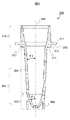
- FIG. 2 is a cross-sectional view along the central axis 205 of the specimen container 200 .
- the sample container 200 is a rotating body around a central axis 205 and has a housing portion 201 and a flange portion 210 .
- the containing portion 201 contains a sample, is inserted into the test tube 101 , and has a cylindrical body portion 202 and a cup-shaped bottom portion 203 connected to the body portion 202 .
- the inner wall of the body portion 202 may be sloped so that the inner diameter decreases from the upper end to the lower end. Since the thickness of the body portion 202 is substantially uniform, when the inner wall is provided with a slope, the outer wall is also provided with a slope.
- the bottom portion 203 has an angle ⁇ 1 formed between the inner wall connecting to the body portion 202 and the central axis 205, and has a gradient of less than 20 degrees, where ⁇ 1> ⁇ 2.
- a cylindrical portion 204 having a cylindrical shape and a planar lower surface may be provided on the outer periphery of the bottom portion 203 .
- the provision of the cylindrical portion 204 allows the sample container 200 to stand on its own.
- the dead volume of the specimen container 200 is determined by the shape of the inner surface of the bottom 203, and in order to increase the dead volume, the inner diameter of the bottom is preferably smaller. However, in order to aspirate a very small amount of sample, it is preferable that the sample pipetting probe 105a can be inserted up to a height of about 1 mm from the bottom surface of the bottom portion 203. larger than diameter.
- the flange portion 210 is provided at the upper end of the housing portion 201 and placed on the open end of the test tube 101, and has a first side surface 211, a first lower surface 212, a second side surface 213, and a second lower surface 214.
- the specimen container 200 can be adapted to test tubes 101 of different diameters.
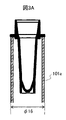
- FIGS. 3A and 3B show the sample container 200 placed on the ⁇ 16 test tube 101a with an outer diameter of 16 mm
- FIG. 3B shows the sample container 200 placed on the ⁇ 13 test tube 101b with an outer diameter of 13 mm.
- the outer diameter of test tube 101 is not limited to 16 mm or 13 mm.
- the first lower surface 212 contacts the open end of the ⁇ 16 test tube 101a, and the distance between the second side surface 213 and the inner wall of the ⁇ 16 test tube 101a allows the sample container 200 to be Horizontal misalignment is limited.
- the outer diameter of the first side surface 211 is made larger than the inner diameter of the ⁇ 16 test tube 101a so that the specimen container 200 does not fall into the ⁇ 16 test tube 101a.
- the second lower surface 214 contacts the opening end of the ⁇ 13 test tube 101b, and the distance between the outer wall of the body portion 202 and the inner wall of the ⁇ 13 test tube 101b causes the sample container to A horizontal displacement of 200 is limited.
- the outer diameter of the second side surface 213 is made larger than the inner diameter of the ⁇ 13 test tube 101b so that the specimen container 200 does not fall into the ⁇ 13 test tube 101b.
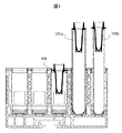
- sample container 200 may be placed not only on the test tube 101 but also on the sample rack 109 as illustrated in FIG.
- the distance between the outer wall of the second side surface 213 or the body portion 202 and the inner wall of the test tube 101 also varies.
- the sample pipetting probe 105a may get caught on the inner wall of the bottom portion 203 and may not be able to descend to a predetermined height, degrading sample pipetting accuracy.
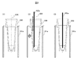
- the horizontal displacement of the sample container 200 is corrected by bringing the sample dispensing probe 105a descending at an appropriate speed into contact with the inner wall of the bottom portion 203 having an appropriate slope.
- the horizontal positional displacement of the sample container 200 is corrected by the horizontal driving force generated when the sample pipetting probe 105a comes into contact with the inner wall of the bottom part 203. be done.
- FIG. (1) shows the sample container 200 that is horizontally displaced with respect to the ⁇ 16 test tube 101a.
- the displacement of the sample container 200 is limited by the difference between the inner diameter of the ⁇ 16 test tube 101 a and the outer diameter of the second side surface 213 .
- (2) when the specimen pipetting probe 105a descends at an appropriate speed, it contacts the inner wall of the bottom part 203, thereby generating horizontal driving force.
- (3) shows the specimen container 200 in which the horizontal displacement with respect to the ⁇ 16 test tube 101a is corrected by the driving force.
- the angle ⁇ 1 formed by the inner wall of the bottom portion 203 and the central axis 205 is preferably less than 20 degrees. That is, when ⁇ 1 ⁇ 20 degrees, the displacement of the sample container 200 can be corrected more appropriately. 5, the operation for correcting the displacement of the specimen container 200 with respect to the ⁇ 16 test tube 101a has been described, but the displacement of the specimen container 200 with respect to the ⁇ 13 test tube 101b can also be corrected by the same operation as in FIG.
- the shape of the bottom portion 203 capable of correcting the positional deviation of the specimen container 200 will be described with reference to FIG.
- the sample pipetting probe 105a In order to correct the positional deviation of the sample container 200 by bringing the sample pipetting probe 105a into contact with the inner wall of the bottom portion 203, the sample pipetting probe 105a must not contact the inner wall of the body portion 202, that is, the following equation must hold. preferable.
- A is the displacement amount of the sample container 200
- B is the radius at the upper end of the bottom portion 203
- C is the outer diameter of the sample dispensing probe 105a.
- the tip of the sample dispensing probe 105a is preferably separated from the bottom 203 appropriately.
- the tip of the sample pipetting probe 105a inserted from the liquid surface height E of the dead volume sample to the depth F have a distance of ⁇ 1 or more from the bottom surface of the bottom part 203, that is, the following equation holds.
- ⁇ 1 is, for example, 1 mm.
- G is the inner diameter of the bottom portion 203 at the liquid level EF.
- the depth D of the bottom portion 203 should be greater than the liquid surface height E of the sample in the dead volume. It is preferable that the following formula holds.
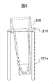
- the sample container 200 may be placed on the ⁇ 16 test tube 101a in an inclined state. When the sample container 200 is tilted, the sample dispensing probe 105a cannot dispense the sample accurately.
- Example 1 in the process of transporting the test tube 101 on which the sample container 200 is placed, the sample container 200 is parallel to the ⁇ 16 test tube 101a due to vibration based on the unevenness of the transport path, that is, the state illustrated in FIG. 3A. be in a state where That is, the specimen container 200 makes a pendulum motion due to vibration with the point of contact with the open end of the ⁇ 16 test tube 101a as a fulcrum, thereby transitioning from a tilted state to a parallel state with respect to the ⁇ 16 test tube 101a.
- the containing portion 201 inserted into the ⁇ 16 test tube 101a is suitable for pendulum motion because the outer diameter of the lower end is smaller than the outer diameter of the upper end.
- the inventors have found through trial production and experiments of the sample container 200 that the outer diameter of the step, that is, the value obtained by dividing the outer diameter of the second side surface 213 by the outer diameter of the bottom portion 203, is preferably 1.6 or more. Found it. The inventors also found that when the central axis of the test tube 101 and the central axis of the sample container 200 are aligned, the gap between the inner wall of the test tube 101 and the outer wall of the bottom part 203 is preferably 2.3 mm or more. was found by trial manufacture and experiment of the sample container 200 .
- the sample container 200 can be easily inserted into the test tube 101, and the air inside the test tube 101 can be released when the sample container 200 is inserted. easier. When the air is difficult to escape, the sample container 200 is slowly dropped into the test tube 101 and inserted. The container 200 eliminates such concerns.
- the stepped corners 215 of the sample container 200 are not chamfered. If the corners 215 are chamfered, the specimen container 200 is likely to shift from a parallel state to an inclined state due to vibration. Therefore, by not chamfering the corners 215, the specimen container 200, which is parallel to the test tube 101, is less likely to tilt due to vibrations caused by the unevenness of the transport path.
- the height of the step is preferably equal to or greater than the height of the unevenness of the conveying path. Since the height of the step is equal to or higher than the height of the unevenness, it is possible to suppress the specimen container 200 from transitioning from a parallel state to an inclined state due to vibration. In order to shift the sample container 200 from the tilted state to the parallel state, the height of the step is preferably as low as possible.
- the inventors found that the height of the step is preferably in the range of 0.5 mm to 2.0 mm through trial production and experiments of sample containers. That is, when the height of the step is in the range of 0.5 mm to 2.0 mm, the sample container 200 easily transitions from the tilted state to the parallel state and hardly transitions from the parallel state to the tilted state. 200 can be kept parallel.
- test tube 101: test tube, 101a: ⁇ 16 test tube, 101b: ⁇ 13 test tube
- 102 sample transport unit
- 103 reagent container
- 104 reagent disk
- 105 sample dispensing unit
- 105a sample dispensing probe
- 106 reagent portion Injection unit
- 106a reagent dispensing probe
- 107 reaction disk
- 108 measurement unit
- 109 sample rack
- 110 washing tank
- 111 reaction container
- 112 stirring unit
- 113 control unit
- 210: flange portion 211: first side surface
- 212 first lower surface
- 213 second side surface
Landscapes
- Health & Medical Sciences (AREA)
- Chemical & Material Sciences (AREA)
- Life Sciences & Earth Sciences (AREA)
- Engineering & Computer Science (AREA)
- Analytical Chemistry (AREA)
- General Health & Medical Sciences (AREA)
- Physics & Mathematics (AREA)
- Biochemistry (AREA)
- General Physics & Mathematics (AREA)
- Immunology (AREA)
- Pathology (AREA)
- Hematology (AREA)
- Biomedical Technology (AREA)
- Quality & Reliability (AREA)
- Chemical Kinetics & Catalysis (AREA)
- Clinical Laboratory Science (AREA)
- Urology & Nephrology (AREA)
- Biophysics (AREA)
- Molecular Biology (AREA)
- Food Science & Technology (AREA)
- Medicinal Chemistry (AREA)
- Ecology (AREA)
- Automatic Analysis And Handling Materials Therefor (AREA)
Abstract
Description
ここで、Aは検体容器200の位置ずれ量、Bは底部203の上端部における半径、Cは検体分注プローブ105aの外径である。
また液面高さEから深さFまで挿入された検体分注プローブ105aが底部203の内壁に接触しないように、次式が成り立つことが好ましい。
ここで、Gは液面高さE-Fにおける底部203の内径である。
また検体容器200は、図8に例示されるように、φ16試験管101aに傾いた状態で載せられる場合がある。検体容器200が傾いた状態では、検体分注プローブ105aは検体を正確に分注できない。
Claims (9)
- 検体を収容するとともに試験管に挿入される収容部と、
前記収容部の上端に設けられて前記試験管の開口端部に載せられるフランジ部を有する検体容器であって、
前記収容部は、筒形状である胴体部と、前記胴体部に連なりカップ形状である底部を有し、
前記底部は、前記胴体部から連なる内壁と中心軸とのなす角が20度未満の勾配を有することを特徴とする検体容器。 - 請求項1に記載の検体容器であって、
前記底部の上端部における内径Bは、前記検体容器の前記試験管に対する水平方向の位置ずれ量をA、前記検体の分注に用いられる検体分注プローブの外径をCとするとき、B>A+C/2であることを特徴とする検体容器。 - 請求項1に記載の検体容器であって、
前記フランジ部の下面には同心円形状の段差が設けられ、
前記段差の外径を前記底部の外径で除した値が1.6以上である、
または、前記試験管の内壁と前記底部の外壁との隙間が2.3mm以上であることを特徴とする検体容器。 - 請求項3に記載の検体容器であって、
前記段差の角部には面取りが施されないことを特徴とする検体容器。 - 請求項3に記載の検体容器であって、
前記段差の高さは、前記試験管が搬送される搬送路の上面が有する凹凸の高さ以上であることを特徴とする検体容器。 - 請求項1に記載の検体容器であって、
前記底部の外周には、円筒形状であって下面が平面形状である円筒部が設けられることを特徴とする検体容器。 - 請求項1に記載の検体容器であって、
前記検体の分注に用いられる検体分注プローブがデッドボリュームの検体の液面高さEから深さFまで挿入されるとき、前記検体分注プローブの先端は前記底部の底面から所定の距離Δ1以上を有することを特徴とする検体容器。 - 請求項1に記載の検体容器であって、
前記底部の深さDは、デッドボリュームの検体の液面高さをEとするとき、D>Eであることを特徴とする検体容器。 - 請求項1に記載の検体容器に収容される前記検体を分析する自動分析装置であって、
前記検体容器が前記試験管に対して水平方向に位置ずれしたときに、前記検体の分注に用いられる検体分注プローブを前記底部の内壁に接触させることにより、前記位置ずれを補正することを特徴とする自動分析装置。
Priority Applications (4)
| Application Number | Priority Date | Filing Date | Title |
|---|---|---|---|
| JP2023522233A JP7595157B2 (ja) | 2021-05-18 | 2022-02-18 | 検体容器及び自動分析装置 |
| EP22802880.9A EP4343336A4 (en) | 2021-05-18 | 2022-02-18 | SAMPLE CONTAINER AND AUTOMATIC ANALYSIS DEVICE |
| US18/286,284 US20240192238A1 (en) | 2021-05-18 | 2022-02-18 | Sample container and automatic analyzer |
| CN202280027347.8A CN117136310A (zh) | 2021-05-18 | 2022-02-18 | 检体容器以及自动分析装置 |
Applications Claiming Priority (2)
| Application Number | Priority Date | Filing Date | Title |
|---|---|---|---|
| JP2021-083890 | 2021-05-18 | ||
| JP2021083890 | 2021-05-18 |
Publications (1)
| Publication Number | Publication Date |
|---|---|
| WO2022244352A1 true WO2022244352A1 (ja) | 2022-11-24 |
Family
ID=84140212
Family Applications (1)
| Application Number | Title | Priority Date | Filing Date |
|---|---|---|---|
| PCT/JP2022/006602 Ceased WO2022244352A1 (ja) | 2021-05-18 | 2022-02-18 | 検体容器及び自動分析装置 |
Country Status (5)
| Country | Link |
|---|---|
| US (1) | US20240192238A1 (ja) |
| EP (1) | EP4343336A4 (ja) |
| JP (1) | JP7595157B2 (ja) |
| CN (1) | CN117136310A (ja) |
| WO (1) | WO2022244352A1 (ja) |
Citations (6)
| Publication number | Priority date | Publication date | Assignee | Title |
|---|---|---|---|---|
| JPH07140137A (ja) * | 1993-11-12 | 1995-06-02 | Toa Medical Electronics Co Ltd | サンプル保冷器 |
| JPH07260643A (ja) * | 1994-03-22 | 1995-10-13 | Sharp Corp | 試料容器 |
| JP2010078483A (ja) * | 2008-09-26 | 2010-04-08 | Fujifilm Corp | 試験管ホルダー |
| JP2013142560A (ja) * | 2012-01-06 | 2013-07-22 | Hitachi High-Technologies Corp | 自動分析装置 |
| JP3185113U (ja) * | 2013-05-21 | 2013-08-01 | 株式会社ユーケンサイエンス | 試料カップ |
| WO2016147239A1 (ja) * | 2015-03-16 | 2016-09-22 | パナソニック株式会社 | ピペットチップ及びピペッティング方法 |
Family Cites Families (7)
| Publication number | Priority date | Publication date | Assignee | Title |
|---|---|---|---|---|
| DE7915283U1 (ja) * | 1979-09-13 | Wilden Kg, 8473 Pfreimd | ||
| US3780935A (en) * | 1972-07-10 | 1973-12-25 | Lukacs & Jacoby Ass | Serum separating method |
| US3963119A (en) * | 1973-10-13 | 1976-06-15 | Lucaks And Jacoby Associates | Serum separating apparatus |
| US4043928A (en) * | 1973-10-31 | 1977-08-23 | Lukacs And Jacoby Associates | Serum separating composition of matter |
| US6878346B2 (en) * | 2002-05-17 | 2005-04-12 | Bayer Corporation | Serum transfer cup |
| JP2008096115A (ja) * | 2006-10-05 | 2008-04-24 | Sysmex Corp | キュベット |
| AT514833B1 (de) * | 2013-10-11 | 2015-07-15 | Greiner Bio One Gmbh | Abnahmebaugruppe, insbesondere für Blutproben |
-
2022
- 2022-02-18 JP JP2023522233A patent/JP7595157B2/ja active Active
- 2022-02-18 WO PCT/JP2022/006602 patent/WO2022244352A1/ja not_active Ceased
- 2022-02-18 US US18/286,284 patent/US20240192238A1/en active Pending
- 2022-02-18 EP EP22802880.9A patent/EP4343336A4/en active Pending
- 2022-02-18 CN CN202280027347.8A patent/CN117136310A/zh active Pending
Patent Citations (6)
| Publication number | Priority date | Publication date | Assignee | Title |
|---|---|---|---|---|
| JPH07140137A (ja) * | 1993-11-12 | 1995-06-02 | Toa Medical Electronics Co Ltd | サンプル保冷器 |
| JPH07260643A (ja) * | 1994-03-22 | 1995-10-13 | Sharp Corp | 試料容器 |
| JP2010078483A (ja) * | 2008-09-26 | 2010-04-08 | Fujifilm Corp | 試験管ホルダー |
| JP2013142560A (ja) * | 2012-01-06 | 2013-07-22 | Hitachi High-Technologies Corp | 自動分析装置 |
| JP3185113U (ja) * | 2013-05-21 | 2013-08-01 | 株式会社ユーケンサイエンス | 試料カップ |
| WO2016147239A1 (ja) * | 2015-03-16 | 2016-09-22 | パナソニック株式会社 | ピペットチップ及びピペッティング方法 |
Non-Patent Citations (1)
| Title |
|---|
| See also references of EP4343336A4 * |
Also Published As
| Publication number | Publication date |
|---|---|
| CN117136310A (zh) | 2023-11-28 |
| EP4343336A1 (en) | 2024-03-27 |
| US20240192238A1 (en) | 2024-06-13 |
| JP7595157B2 (ja) | 2024-12-05 |
| EP4343336A4 (en) | 2025-06-18 |
| JPWO2022244352A1 (ja) | 2022-11-24 |
Similar Documents
| Publication | Publication Date | Title |
|---|---|---|
| CN102066949B (zh) | 自动分析装置 | |
| JP7414911B2 (ja) | 自動分析装置 | |
| EP2746736B1 (en) | System for managing of bulk liquids and/or solids | |
| US9889443B2 (en) | Sample analyzer and sample analyzing method | |
| US11692916B2 (en) | System for mixing contents of containers and related methods of use | |
| JPH0894636A (ja) | 検体の自動分析方法および装置 | |
| JP4764298B2 (ja) | キュベットホルダー、キュベット列およびこれらを具備してなる分析装置 | |
| WO2008030755A1 (en) | Micro-sample cup rack adapter | |
| WO2016136377A1 (ja) | 自動分析装置 | |
| JP2006513401A (ja) | 液体のメニスカス及び振動を制御する内部構造を備えた測定先端 | |
| WO2010032507A1 (ja) | 分注装置、自動分析装置および分注不良確認方法 | |
| CN103630696B (zh) | 试剂容器 | |
| JP7132366B2 (ja) | 検体ラック、検体ラック用アダプタおよび自動分析装置 | |
| WO2022244352A1 (ja) | 検体容器及び自動分析装置 | |
| JP2022133528A (ja) | 自動分析装置 | |
| JP2008003057A (ja) | 分析装置と分析方法 | |
| JP2014228318A (ja) | 自動分析装置および自動分析方法 | |
| JP2000235037A (ja) | 試料分析装置 | |
| JP2007047001A (ja) | 自動分析装置 | |
| JP2023085943A (ja) | 自動分析装置 | |
| WO2025150336A1 (ja) | 自動分析装置及び自動分析方法 | |
| WO2024195230A1 (ja) | ピアス機構及びこれを備えた自動分析装置 | |
| WO2020230401A1 (ja) | 自動分析装置 | |
| JP2009162734A (ja) | 自動分析装置 |
Legal Events
| Date | Code | Title | Description |
|---|---|---|---|
| 121 | Ep: the epo has been informed by wipo that ep was designated in this application |
Ref document number: 22802880 Country of ref document: EP Kind code of ref document: A1 |
|
| WWE | Wipo information: entry into national phase |
Ref document number: 18286284 Country of ref document: US |
|
| WWE | Wipo information: entry into national phase |
Ref document number: 2023522233 Country of ref document: JP |
|
| WWE | Wipo information: entry into national phase |
Ref document number: 2022802880 Country of ref document: EP |
|
| NENP | Non-entry into the national phase |
Ref country code: DE |
|
| ENP | Entry into the national phase |
Ref document number: 2022802880 Country of ref document: EP Effective date: 20231218 |