WO2022264338A1 - Dispositif de commande, dispositif de vérification d'interférence et système de commande - Google Patents
Dispositif de commande, dispositif de vérification d'interférence et système de commande Download PDFInfo
- Publication number
- WO2022264338A1 WO2022264338A1 PCT/JP2021/022930 JP2021022930W WO2022264338A1 WO 2022264338 A1 WO2022264338 A1 WO 2022264338A1 JP 2021022930 W JP2021022930 W JP 2021022930W WO 2022264338 A1 WO2022264338 A1 WO 2022264338A1
- Authority
- WO
- WIPO (PCT)
- Prior art keywords
- interference
- unit
- movement
- movement amount
- moving part
- Prior art date
- Legal status (The legal status is an assumption and is not a legal conclusion. Google has not performed a legal analysis and makes no representation as to the accuracy of the status listed.)
- Ceased
Links
Images






Classifications
-
- G—PHYSICS
- G05—CONTROLLING; REGULATING
- G05B—CONTROL OR REGULATING SYSTEMS IN GENERAL; FUNCTIONAL ELEMENTS OF SUCH SYSTEMS; MONITORING OR TESTING ARRANGEMENTS FOR SUCH SYSTEMS OR ELEMENTS
- G05B19/00—Program-control systems
- G05B19/02—Program-control systems electric
- G05B19/18—Numerical control [NC], i.e. automatically operating machines, in particular machine tools, e.g. in a manufacturing environment, so as to execute positioning, movement or co-ordinated operations by means of program data in numerical form
- G05B19/406—Numerical control [NC], i.e. automatically operating machines, in particular machine tools, e.g. in a manufacturing environment, so as to execute positioning, movement or co-ordinated operations by means of program data in numerical form characterised by monitoring or safety
- G05B19/4061—Avoiding collision or forbidden zones
-
- G—PHYSICS
- G05—CONTROLLING; REGULATING
- G05B—CONTROL OR REGULATING SYSTEMS IN GENERAL; FUNCTIONAL ELEMENTS OF SUCH SYSTEMS; MONITORING OR TESTING ARRANGEMENTS FOR SUCH SYSTEMS OR ELEMENTS
- G05B2219/00—Program-control systems
- G05B2219/30—Nc systems
- G05B2219/35—Nc in input of data, input till input file format
- G05B2219/35316—Interference checking between tool, machine, part, chuck, machining range
-
- G—PHYSICS
- G05—CONTROLLING; REGULATING
- G05B—CONTROL OR REGULATING SYSTEMS IN GENERAL; FUNCTIONAL ELEMENTS OF SUCH SYSTEMS; MONITORING OR TESTING ARRANGEMENTS FOR SUCH SYSTEMS OR ELEMENTS
- G05B2219/00—Program-control systems
- G05B2219/30—Nc systems
- G05B2219/49—Nc machine tool, till multiple
- G05B2219/49141—Detect near collision and slow, stop, inhibit movement tool
Definitions
- the present invention relates to a control device, an interference check device, and a control system.
- FIG. 10 is a diagram showing a spindle 301 to which a tool 303 as a moving part is attached, a table 305 and a work 309 as interference objects, and a jig 307 for fixing the work 309 . If the spindle 301 and the tool 303 continue to move in the direction of the arrow in the figure, the spindle 301 will eventually interfere with the jig 307 . If interference occurs, moving parts and interfering objects may be damaged, and machine shafts and motors may malfunction. Therefore, some control devices have an interference check function that checks the possibility of interference occurring between the moving part and an interfering object in advance and stops the movement of the moving part when interference occurs.
- the interference check function includes a technology that checks for interference on the control device side and a technology that checks for interference on the PC side connected to the control device. Controllers devote much of their computing resources to controlling industrial machines. When the interference check is performed on the control device side, only simple processing can be performed in many cases. Therefore, when the shape definition of an interfering object is complicated, or when the computational resources on the control device side cannot perform an interference check, a function for performing an interference check on the PC side connected to the control device is used (for example, Patent Document 1 Such).
- FIG. 11 is a sequence chart showing the flow of processing when the control device and the PC cooperate to check for interference.
- the control device calculates the coordinate values of the position where the interference check is to be performed, and transmits the calculated coordinate values to the PC at time tA .
- the PC which received the coordinate values at time tB , moves the moving part to the position of the sent coordinate values using a pre-stored model of the moving part and the interfering object (for example, a three-dimensional model). check whether there is any interference. Then, the result of the interference check is transmitted to the control device at time tC .
- the control device Upon receiving the result of the interference check at time tD , the control device determines whether or not to stop the movement of the moving unit based on the result of the interference check. If it is necessary to stop the moving part, the stopping process of the moving part is started at time tE . Then, the moving part stops at time tF .
- the preceding position which is the movement destination of the moving part after these times have passed, is calculated as the coordinate value to be subjected to the interference check, and the interference check at this preceding position is performed on the PC side.
- the control device needs to manage two types of data, the current position and the preceding position. This poses a problem that the processing for managing data becomes complicated.
- the prediction candidates for the preceding position may be divided into two or more depending on the situation. In such a case, there is a problem that if the prediction of the preceding position is incorrect, the interference check cannot be performed correctly.
- the preceding position cannot be predicted in advance, such as in manual operation, there are cases where it is desired to perform a PC-linked interference check. Therefore, in the PC-linked interference check, there is a demand for a technique that enables the interference check to be performed without transmitting the preceding position to the PC.
- the control device newly introduces the concept of prohibited movement amount, and the control device side determines interference based on the prohibited movement amount calculated by the interference check device, thereby solving the above problem. do.
- one aspect of the present disclosure is a control device for controlling movement of a moving part of an industrial machine along an axis based on a machining program, wherein interference checking is performed between the moving part and an interfering object.
- a control device that performs an interference check in cooperation with a device, a command analysis unit that analyzes blocks of the machining program; a distribution processing unit that calculates the position of the moving part updated by the amount of movement and notifies the interference check device; and a movement from the position of the moving part calculated by the interference check device based on the notified position.
- an interference determination unit that determines whether or not there is interference between the moving unit and the interfering object based on a prohibited movement amount that is a distance at which interference may occur in the moving unit and the interfering object;
- the control device stops the movement of the moving unit when the interference determination unit determines that the interference occurs.
- Another aspect of the present disclosure is an interference check device that performs an interference check between a moving part that moves along an axis of an industrial machine and an interfering object, wherein a model that stores a model of the moving part and the interfering object based on a data storage unit, the position of the moving unit notified from a control device that controls the industrial machine, and models of the moving unit and the interfering object stored in the model data storage unit; a prohibited movement amount calculation unit that calculates a prohibited movement amount that may cause interference by moving from the position of the unit, and transmits the calculated prohibited movement amount to the control device; It is an interference check device.
- the interference check device includes a model data storage unit that stores models of the moving unit and the interfering object, a position of the moving unit notified from the control unit, and the Prohibited movement amount calculation for calculating a prohibited movement amount that may cause interference by moving from the position of the moving part based on the models of the moving part and the interfering object stored in the model data storage unit.
- a command analysis unit that analyzes blocks of the machining program; and a distribution movement amount for each distribution cycle based on the analysis result of the command analysis unit, and the distribution movement amount.
- a distribution processing unit that calculates the updated position of the moving unit and notifies it to the interference check device;
- the control system includes an interference determination unit that determines presence or absence of interference, and stops movement of the moving unit when the interference determining unit determines that interference between the moving unit and the interfering object occurs.
- FIG. 1 is a schematic hardware configuration diagram of a control device and an interference check device according to an embodiment of the present invention
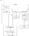
- FIG. 1 is a block diagram showing schematic functions of a control device and an interference check device according to an embodiment of the present invention
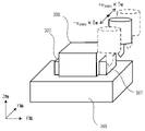
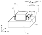
- FIG. It is a figure which shows the example of a moving part and an interfering object. It is a figure which shows the example which moves a moving part to a Y-axis direction. It is a figure which shows the example which moves a moving part to an X-axis direction. It is a figure which shows the example which moves a moving part to B-axis direction.
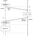
- 4 is a sequence chart showing the flow of interference check according to one embodiment of the present invention
- FIG. 10 is a diagram illustrating the relationship between the actual position of the moving unit when calculating the current position and the current position;
- FIG. 9 is a diagram illustrating the relationship between the actual position, current position, and check position of the moving part when calculating the prohibited movement amount;
- FIG. 10 is a diagram illustrating the relationship between the actual position, current position, check position, and interference position of the moving unit at the time of interference determination;
- FIG. 5 is a diagram illustrating the relationship between the actual position, current position, check position, and interference position of the moving part when the moving part is stopped;
- FIG. 4 is a block diagram showing a modification of the control device and the interference check device according to one embodiment of the present invention; It is a figure explaining interference of a moving part and an interfering object.
- FIG. 10 is a sequence chart showing the flow of PC-linked interference check;
- FIG. 10 is a sequence chart showing the flow of PC-linked interference check;
- FIG. 10 is a sequence chart showing the flow of PC-linked interference check;
- FIG. 1 is a schematic hardware configuration diagram showing essential parts of a control device according to an embodiment of the present invention.
- a control device 1 of the present invention constitutes a control system 4 together with an interference check device 2 built on a personal computer provided side by side.
- a control device 1 controls an industrial machine 3 such as a machine tool or a machining center.
- the CPU 11 included in the control device 1 is a processor that controls the control device 1 as a whole.
- the CPU 11 reads a system program stored in the ROM 12 via the bus 22 and controls the entire control device 1 according to the system program.
- the RAM 13 temporarily stores calculation data, display data, various data input from the outside, and the like.
- the non-volatile memory 14 is composed of, for example, a memory backed up by a battery (not shown) or an SSD (Solid State Drive), and retains the storage state even when the control device 1 is powered off.
- the nonvolatile memory 14 stores control programs and data read from an external device 72 via the interface 15 , control programs and data input from the input device 71 via the interface 18 , and fog computer data via the network 5 . Control programs, data, and the like acquired from other devices such as 6 and cloud server 7 are stored.
- the data stored in the nonvolatile memory 14 includes, for example, data relating to the mechanical configuration of the industrial machine 3, data relating to interfering objects such as workpieces and jigs, data relating to movement of the moving part along each axis, and others. may include data relating to each physical quantity detected by a sensor (not shown) attached to the industrial machine 3 .
- the control program and data stored in the nonvolatile memory 14 may be developed in the RAM 13 at the time of execution/use. Various system programs such as a known analysis program are written in advance in the ROM 12 .
- the interface 15 is an interface for connecting the CPU 11 of the control device 1 and an external device 72 such as an external storage medium. From the external device 72 side, for example, a control program and setting data used for controlling the industrial machine 3 are read. Control programs and setting data edited in the control device 1 can be stored in an external storage medium such as a CF card or USB memory (not shown) via the external device 72 .
- a PLC (Programmable Logic Controller) 16 executes a ladder program to control the industrial machine 3 and peripheral devices of the industrial machine 3 (for example, a tool changer, an actuator such as a robot, etc., attached to the industrial machine 3). (sensors, etc.) via the I/O unit 19 for control. It also receives signals from various switches on the operation panel and peripheral devices provided on the main body of the industrial machine 3 , performs necessary signal processing, and then transfers the signals to the CPU 11 .
- the interface 20 is an interface for connecting the CPU of the control device 1 and the interference check device 2 by wire or wirelessly.
- the connection between the control device 1 and the interference check device 2 is, for example, serial communication such as RS-485, Ethernet (registered trademark) communication, optical communication, wireless LAN, Wi-Fi (registered trademark), Bluetooth (registered trademark). or the like may be used for communication.
- the control device 1 exchanges data with the interference check device 2 via the interface 20 .
- each data read into the memory, data obtained as a result of executing the program, etc. are output via the interface 17 and displayed.
- An input device 71 composed of a keyboard, a pointing device, and the like passes commands, data, and the like based on operations by the operator to the CPU 11 via the interface 18 .
- the axis control circuit 30 for moving the moving part provided in the industrial machine 3 receives the movement command amount from the CPU 11 and outputs the movement command to the servo amplifier 40 respectively.
- the servo amplifier 40 receives this command and drives the servo motors 50 provided in the industrial machine 3 .
- the servo motor 50 incorporates a position/velocity detector, and feeds back a position/velocity feedback signal from this position/velocity detector to the axis control circuit 30 to perform position/velocity feedback control.
- Only one axis control circuit 30, one servo amplifier 40, and one servomotor 50 are shown in the hardware configuration diagram of FIG. Only the number of copies is prepared.
- a spindle control circuit 60 receives a spindle rotation command and outputs a spindle speed signal to a spindle amplifier 61 .
- the spindle amplifier 61 receives this spindle speed signal, rotates the spindle motor 62 of the industrial machine at the commanded rotational speed, and drives the tool.
- a position coder 63 is coupled to the spindle motor 62 , the position coder 63 outputs feedback pulses in synchronization with the rotation of the main shaft, and the feedback pulses are read by the CPU 11 .
- the interference check device 2 is built on a PC attached to the control device 1 .
- a CPU 211 included in the interference check device 2 is a processor that controls the interference check device 2 as a whole.
- the CPU 211 reads the system program stored in the ROM 212 via the bus 222 and controls the entire interference check device 2 according to the system program.
- the RAM 213 temporarily stores calculation data, display data, various data input from the outside, and the like.
- the non-volatile memory 214 is composed of, for example, a memory backed up by a battery (not shown) or an SSD (Solid State Drive), etc., and retains the memory state even when the power of the interference check device 2 is turned off.
- the nonvolatile memory 214 stores data acquired from the control device 1 via the interface 220, data and programs read from the external device 272 via the interface 215, data and programs input via the input device 271, and the like. is stored.
- the data and programs stored in the nonvolatile memory 214 may be developed in the RAM 213 during execution/use.
- the ROM 212 is pre-written with various system programs such as known processing programs, analysis programs, and 3D simulation programs.
- the interface 215 is an interface for connecting the CPU 211 of the interference check device 2 and an external device 272 such as a USB device. From the external device 272 side, for example, programs and parameters used for analysis can be read. Programs and parameters edited in the interference check device 2 can be stored in external storage means via the external device 272 .
- the interface 220 is an interface for connecting the CPU 211 of the interference check device 2 and the control device 1 by wire or wirelessly.
- the interference check device 2 exchanges data with the control device 1 via the interface 220 .
- each data read into the memory data obtained as a result of executing the machining program, system program, etc. are output and displayed via the interface 217.
- An input device 271 composed of a keyboard, a pointing device, and the like passes commands, data, and the like based on the operator's operation to the CPU 211 via the interface 218 .
- FIG. 2 is a schematic block diagram showing the functions of the control device 1 according to the first embodiment of the present invention. Each function provided in the control device 1 according to the present embodiment is realized by the CPU 11 provided in the control device 1 shown in FIG.
- the control device 1 of this embodiment includes a command analysis unit 110, a distribution processing unit 115, a movement command output unit 120, an acceleration/deceleration processing unit 125, a servo control unit 130, and an interference determination unit 135.
- the interference check device 2 also includes a prohibited movement amount calculator 210 .
- a machining program 180 used for controlling the industrial machine 3 is stored in advance in the RAM 13 to nonvolatile memory 14 of the control device 1 .
- the command analysis unit 110 reads commands block by block from the machining program 180, analyzes the commands, and creates data in an executable format. Command analysis unit 110 outputs executable data to distribution processing unit 115 .
- the distribution processing unit 115 calculates the distribution movement amount for each distribution cycle for moving each axis at the commanded movement amount and speed based on the execution format data input from the command analysis unit 110 .
- the distribution processing unit 115 outputs the calculated distributed movement amount to the movement command output unit 120 and the prohibited movement amount calculation unit 210 included in the interference check device 2 .
- the distribution processing unit 115 updates the current position information of each axis of the industrial machine 3 stored in the current position register (not shown) by adding the calculated distributed movement amount. Then, the updated current position information is output as a check position to the interference determination unit 135 and the prohibited movement amount calculation unit 210 provided in the interference check device 2 .
- the movement command output unit 120 outputs the distributed movement amount calculated by the distribution processing unit 115 to the acceleration/deceleration processing unit 125 . Further, the movement command output unit 120 stops outputting the distributed movement amount to the acceleration/deceleration processing unit 125 when the interference determination unit 135 determines that interference will occur.
- the acceleration/deceleration processing unit 125 performs predetermined acceleration/deceleration processing on the distributed movement amount input from the movement command output unit 120 . Then, the acceleration/deceleration processed movement command is output to the servo control unit 130 with the distribution movement amount subjected to the acceleration/deceleration process. Then, the servo control unit 130 drives and controls the servo motor 50 attached to the industrial machine 3 based on the input distributed movement amount.
- the interference determination unit 135 determines whether there is interference in the movement of the moving unit of the industrial machine 3 based on the check position input from the distribution processing unit 115 and the prohibited movement amount of each axis input from the interference check device 2. do. More specifically, the interference determination unit 135 determines the distribution movement amount of each axis from the check position input from the distribution processing unit 115 (distribution movement amount calculated by the distribution processing unit 115) and the interference check device 2 Compare with the prohibited movement amount of each axis from the input check position. Then, when the distributed movement amount is equal to or greater than the prohibited movement amount, it is determined that interference occurs. When the collision determination unit 135 determines that interference will occur, the collision determination unit 135 outputs that effect to the movement command output unit 120 .
- each function provided in the interference check device 2 according to the present embodiment is realized by the CPU 211 provided in the interference check device 2 shown in FIG. be done.
- the interference check device 2 of this embodiment includes a prohibited movement amount calculator 210 .
- a model data storage unit 280 in which models indicating shapes of interfering objects such as moving parts of the industrial machine 3 and workpieces, tables, and jigs are stored in advance. are provided.
- the prohibited movement amount calculation unit 210 performs simple simulation processing based on the model of the moving unit and the interfering object stored in the model data storage unit 280 . Then, a prohibited movement amount is calculated, which indicates how far the moving part must be moved along each axis from the check position before there is a possibility that the moving part and the interfering object will interfere with each other.
- the prohibited movement amount calculator 210 transmits the calculated prohibited movement amount of each axis to the control device 1 .
- FIG. 3 is a diagram of a spindle 301 to which a tool 303 as a moving part is attached, a table 305 and a work 309 as interference objects, and a jig 307 for fixing the work 309 are arranged.
- the prohibited movement amount calculation unit 210 performs simulation processing and calculates the positional relationship between the movement unit at the check position and the interfering object.
- FIG. 3 shows a case where the current position output by the distribution processing unit 115 to the prohibited movement amount calculation unit 210 has a moving part.
- the prohibited movement amount calculation unit 210 calculates, for each axis, the distance that the movement unit can move from the check position within a predetermined check time width TW .
- TW check time width
- the moving part can move in the Y-axis direction at the allowable speed vymax .
- the moving part can move in the Y-axis direction by a distance of v ymax ⁇ T W during the check time width T W . Therefore, as exemplified in FIG. 4, the prohibited movement amount calculation unit 210 moves to a position apart from the check position by a distance of ⁇ v ymax ⁇ T W along the Y axis. Simulate whether interference will occur.
- the moving unit is moved in predetermined increments of ⁇ d y within a distance range of v ymax ⁇ T W , and a simulation is performed at each position. Then, it is determined whether or not interference occurs in each case, and the range of distances in which interference does not occur is obtained. The distance at which this interference does not occur may be calculated as the prohibited movement amount. In the example of FIG. 4, even if the moving part is moved along the Y-axis by a distance of ⁇ v ymax ⁇ T W , interference does not occur between the moving part and the interfering object, so the prohibited movement amount in the Y-axis direction is Do not calculate (Y-axis is unrestricted in both positive and negative directions).
- the prohibited movement amount calculation unit 210 moves to a position apart from the check position by a distance of ⁇ v xmax ⁇ T W along the X axis. Simulate whether interference will occur.
- the prohibited movement amount calculator 210 calculates the prohibited movement amount in the negative direction of the X-axis as d xcol (there is no limit in the positive direction of the X-axis).
- the prohibited movement amount calculator 210 can calculate the prohibited movement amount not only for the linear axis but also for the rotary axis. For example, as illustrated in FIG. 6, in an industrial machine 3 having a B-axis, consider the case of calculating the prohibited movement amount of the B-axis. At this time, if the B-axis is rotatable at the allowable angular velocity ⁇ amax , the moving part can rotate in the B-axis direction by an angle of ⁇ amax ⁇ T W during the check time width T W . As exemplified in FIG.
- the prohibited movement amount calculation unit 210 simulates whether or not interference will occur with an interfering object when rotated from the check position along the B axis by an angle of ⁇ amax ⁇ T W . do.
- the prohibited movement amount calculator 210 calculates the prohibited movement amount in the negative direction of the B-axis as d acol (there is no limit in the positive direction of the B-axis).
- the method of calculating the prohibited movement amount described above does not take into consideration the combined range of movement of each axis of the industrial machine 3 . Therefore, interference in a strict sense cannot be checked.
- T W set as the time range of the interference check it is possible to perform the interference check with sufficient accuracy. For example, by setting T W to several hundred milliseconds or less, it is possible to perform an interference check with a degree of precision that can avoid interference that may occur in machining with a normal machine tool.
- the amount of calculation required for the interference check is remarkably reduced compared to the case where the interference check is performed in consideration of the combined range of movement of each axis. Therefore, by adopting the method of calculating the prohibited movement amount described above, the PC used in the interference check device 2 can be made relatively inexpensive, and the overall introduction cost can be suppressed.
- the amount of calculation in the interference check device 2 is sufficiently small, so even if a strict interference check is performed in consideration of the combined movement amount of each axis. good.
- the interference check device 2 by constructing the interference check device 2 on a high-performance PC, even if the number of axes is large, a stricter prohibited movement amount can be calculated in consideration of the combined movement amount of each axis. It can also be used as In such a configuration, the prohibited movement amount of each axis may be created in the form of a function whose value changes depending on the range of movement amounts of other axes, and output to the control device 1 .
- the prohibited movement amount calculation section 210 calculates a value smaller by a predetermined margin amount as the prohibited movement amount. For example, in the above example, the prohibited movement amount calculation unit 210 calculates the prohibited movement amount in the negative direction of the X-axis as d xcol ⁇ M x (where M x is the X-axis margin amount), and the prohibited amount of movement in the negative direction of the B-axis as d acol - M a (M a is the margin amount of the B axis).
- FIG. 7 is a sequence chart showing the flow of interference check processing in the control system 4 in which the control device 1 and the interference check device 2 cooperate with each other.
- the control device 1 calculates the coordinate values of the position where the interference check is performed, and transmits the calculated coordinate values to the interference check device 2 at time t A. do.
- the interference check device 2 having received the coordinate values of the check position at time tB, uses a pre - stored model of the moving part and the interfering object to calculate a predetermined check time width TW based on the sent coordinate values of the check position. It is checked whether or not interference occurs within the range in which the moving part can move along each axis.
- the prohibited movement amount of each axis is calculated based on the check result.
- the calculated prohibited movement amount for each axis is sent to the controller at time tC .
- the controller 1 which has received the prohibited movement amount of each axis at time tD , compares the currently output distributed movement amount of each axis with the prohibited movement amount, and determines whether or not interference will occur. Then, when it is determined that interference will occur, the stop processing of the moving unit is started at time t E . Then, the moving part stops at time tF .
- FIGS. 8A to 8D the actual position of the moving part in the industrial machine 3 and the current position of the moving part set in the current position register of the control device 1 at each point in time when the interference check is performed.
- the relationship between the position and the check position checked by the interference check device 2 will be described.
- arrows indicate the moving path 405 of the moving part commanded by the machining program 180.
- FIG. A black circle indicates the actual position 410 of the moving part
- a white circle indicates the current position 415 of the moving part set in the register
- a white triangle indicates the check position 420
- a black square indicates the interference position 425 .
- FIG. 8A is a diagram showing the positional relationship between the actual position 410 and the current position 415 at time t A shown in FIG.
- the current position of the moving unit set in the current position register is updated based on the distributed movement amount.
- the updated current position is output to the interference check device 2 as the check position.
- the actual position 410 of the moving part of the industrial machine 3 always lags behind the updated current position 415 in the controller 1 while the moving part is moving. It will happen.
- FIG. 8B is a diagram showing the positional relationship of the actual position 410, current position 415, and check position 420 at time tB .
- the current position output from the distribution processing unit 115 is input to the interference check device 2 as a check position, each process of analysis and distribution of the machining program 180 in the control device 1 and the processing of distribution in the industrial machine 3 movement of the moving part is performed. Therefore, as shown in FIG. 8B, actual position 410 and current position 415 are further along movement path 405 than at time t A .
- the check position 420 is the same position as the current position 415 at time t A . Thereafter, the actual position 410 and the current position 415 move along the movement path 405 even during the calculation of the prohibited movement amount by the prohibited movement amount calculation unit 210 .
- FIG. 8C is a diagram showing the positional relationship of the actual position 410, current position 415, check position 420, and interference position 425 at time tD .
- the actual position 410 and the current position 415 further advance along the movement path 405 until the prohibited movement amount of each axis is calculated by the prohibited movement amount calculation unit 210 and output to the control device 1 .
- the interference determination unit 135 determines that interference will occur (time t E )
- the actual position 410 of the moving unit is the check position + prohibited movement amount position, that is, at least You must be at least a distance in front of you. If it is located at least the distance related to stopping, the movement of the moving part stops before the interference position 425 at time t F as shown in FIG. 8D.
- the interference check device 2 calculates the prohibited movement amount, and the control device 1 receives the calculated prohibited movement amount. Until then, the control device 1 continues to analyze the command of the machining program 180 to update the current position, and the moving part of the industrial machine 3 continues to move. Therefore, from the point of view of the control device 1, until the judgment result at the check position output to the interference check device 2 is returned, the interference judgment unit 135 judges interference using the previous check position and the prohibited movement amount. There is a need to.
- the control device 1 having the above configuration can perform an interference check in cooperation with the interference check device 2 (PC) without transmitting the preceding position to the interference check device 2 . Since the control device 1 does not need to manage the two position coordinates of the current position and the preceding position, it is possible to manage the movement position of the movement unit with a simple process. In addition, since the interference check can be performed using the position currently grasped by the control device 1, it is possible to cope with the case where the prediction candidates for the preceding position are divided into two or more depending on the situation. Similarly, it can also be applied when the preceding position cannot be predicted in advance, such as in manual operation.
- the present invention is not limited to the above-described examples of the embodiments, and can be implemented in various modes by adding appropriate modifications.
- useful information for specifying the range in which the moving unit can move in the check time width TW is sent to the interference check device together with the check position.
- Useful information for specifying the range in which the moving part can move in this check time width TW includes information such as permissible speed, permissible acceleration, permissible jerk, current speed, and whether or not the axis moves. are exemplified.
- the prohibited movement amount calculation section 210 can use these pieces of information to more strictly calculate the range in which the movement section can move within the check time width T W . For example, since the speed that can be reached within the check time width T W can be calculated from the current speed and the allowable acceleration, it is possible to limit the movement range of the moving part by using this as the maximum speed. Also, if an axis does not move, the calculation for that axis can be omitted. These pieces of information contribute to reducing the computational cost of the interference check device 2 .
- the interference determination unit 135 compares the prohibited movement amount and the distributed movement amount calculated by the distribution processing unit 115, and determines that interference occurs when the distributed movement amount is equal to or greater than the prohibited movement amount. ing. However, the interference determination unit 135 may use the distributed movement amount for which the acceleration/deceleration processing unit 125 has performed the predetermined acceleration/deceleration processing as the prohibited movement amount comparison target.
- FIG. 9 is a schematic block diagram showing the functions of the control device 1 when a position calculated based on the distributed movement amount subjected to the acceleration/deceleration processing by the acceleration/deceleration processing unit 125 is used as the check position. be.
- the interference determination unit 135 determines the amount of distributed movement from the check position input from the acceleration/deceleration processing unit 125 and the inhibition of each axis from the check position input from the interference check device 2. Compare with the amount of movement. Then, when the distributed movement amount from the check position input from the acceleration/deceleration processing unit 125 is equal to or greater than the prohibited movement amount, it is determined that interference occurs.
- the collision determination unit 135 determines that interference will occur, the collision determination unit 135 outputs that effect to the movement command output unit 128 .
- the movement command output unit 128 stops outputting the movement command to the servo control unit 130 .
- the distributed movement amount that has undergone acceleration/deceleration processing by the acceleration/deceleration processing unit 125 is output to the servo control unit 130 as a movement command. Therefore, the control device 1 of this modification can perform a stricter interference check than when interference is determined based on the distribution movement amount calculated by the distribution processing unit 115 .
- Control Device 2 Interference Check Device 3 Industrial Machine 4 Control System 5 Network 6 Fog Computer 7 Cloud Server 11
- CPU 12 ROMs 13 RAM 14 non-volatile memory 15, 17, 18, 20 interface 19 I/O unit 22 bus 30 axis control circuit 40
- servo amplifier 50 servo motor 60 spindle control circuit 61 spindle amplifier 62 spindle motor 63 position coder 70 display device 71 input device 72 external Equipment 110 Command analysis unit 115 Distribution processing unit 120 Movement command output unit 125 Acceleration/deceleration processing unit 130 Servo control unit 135 Interference determination unit 180 Machining program 210 Prohibited movement amount calculation unit 211 CPU 212 ROMs 213 RAM 214 nonvolatile memory 215, 217, 218, 220 interface 222 bus 270 display device 271 input device 272 external device 280 model data storage unit 301 spindle 303 tool 305 table 307 jig 309 workpiece 405 movement path 410 actual position 415 current position 420 check Position 425 Interference position
Landscapes
- Engineering & Computer Science (AREA)
- Human Computer Interaction (AREA)
- Manufacturing & Machinery (AREA)
- Physics & Mathematics (AREA)
- General Physics & Mathematics (AREA)
- Automation & Control Theory (AREA)
- Numerical Control (AREA)
Abstract
Priority Applications (5)
| Application Number | Priority Date | Filing Date | Title |
|---|---|---|---|
| CN202180099143.0A CN117425862A (zh) | 2021-06-16 | 2021-06-16 | 控制装置、干扰检查装置以及控制系统 |
| PCT/JP2021/022930 WO2022264338A1 (fr) | 2021-06-16 | 2021-06-16 | Dispositif de commande, dispositif de vérification d'interférence et système de commande |
| DE112021007472.5T DE112021007472T5 (de) | 2021-06-16 | 2021-06-16 | Steuervorrichtung, kollisionsprüfungsvorrichtung und steuersystem |
| JP2023528863A JP7568854B2 (ja) | 2021-06-16 | 2021-06-16 | 制御装置、干渉チェック装置、及び制御システム |
| US18/567,360 US20250116987A1 (en) | 2021-06-16 | 2021-06-16 | Control device, interference check device, and control system |
Applications Claiming Priority (1)
| Application Number | Priority Date | Filing Date | Title |
|---|---|---|---|
| PCT/JP2021/022930 WO2022264338A1 (fr) | 2021-06-16 | 2021-06-16 | Dispositif de commande, dispositif de vérification d'interférence et système de commande |
Publications (1)
| Publication Number | Publication Date |
|---|---|
| WO2022264338A1 true WO2022264338A1 (fr) | 2022-12-22 |
Family
ID=84527309
Family Applications (1)
| Application Number | Title | Priority Date | Filing Date |
|---|---|---|---|
| PCT/JP2021/022930 Ceased WO2022264338A1 (fr) | 2021-06-16 | 2021-06-16 | Dispositif de commande, dispositif de vérification d'interférence et système de commande |
Country Status (5)
| Country | Link |
|---|---|
| US (1) | US20250116987A1 (fr) |
| JP (1) | JP7568854B2 (fr) |
| CN (1) | CN117425862A (fr) |
| DE (1) | DE112021007472T5 (fr) |
| WO (1) | WO2022264338A1 (fr) |
Cited By (1)
| Publication number | Priority date | Publication date | Assignee | Title |
|---|---|---|---|---|
| EP4439370A1 (fr) | 2023-03-29 | 2024-10-02 | G.D S.p.A. | Procédé de simulation du mouvement d'au moins une partie d'une machine automatique pour la fabrication ou le conditionnement d'articles de consommation |
Citations (4)
| Publication number | Priority date | Publication date | Assignee | Title |
|---|---|---|---|---|
| JPH0927046A (ja) * | 1995-07-11 | 1997-01-28 | Fujitsu Ltd | 干渉チェック方法 |
| JP2007172068A (ja) * | 2005-12-19 | 2007-07-05 | Fanuc Ltd | 数値制御装置 |
| JP2009075799A (ja) * | 2007-09-20 | 2009-04-09 | Okuma Corp | 工作機械数値制御装置 |
| WO2010004960A1 (fr) * | 2008-07-10 | 2010-01-14 | シチズンマシナリー株式会社 | Dispositif de contrôle d'interférences, procédé de contrôle d'interférences, et machine-outil comportant le dispositif de contrôle d'interférences |
Family Cites Families (9)
| Publication number | Priority date | Publication date | Assignee | Title |
|---|---|---|---|---|
| JP4221016B2 (ja) * | 2006-07-25 | 2009-02-12 | ファナック株式会社 | 干渉チェックを行う数値制御装置 |
| JP4298770B2 (ja) * | 2007-08-28 | 2009-07-22 | ファナック株式会社 | 干渉チェック機能を備えた数値制御装置 |
| JP5167788B2 (ja) * | 2007-11-30 | 2013-03-21 | 株式会社ジェイテクト | 工作機械の干渉検出装置 |
| JP6209392B2 (ja) * | 2013-08-12 | 2017-10-04 | Dmg森精機株式会社 | 干渉確認装置 |
| JP6321583B2 (ja) * | 2015-06-30 | 2018-05-09 | ファナック株式会社 | 速度変化に対応した3次元干渉チェックを行う数値制御装置 |
| JP6411964B2 (ja) * | 2015-07-27 | 2018-10-24 | ファナック株式会社 | 工作機械とロボットのリアルタイム干渉確認システム |
| JP6948632B2 (ja) * | 2017-02-10 | 2021-10-13 | 株式会社リコー | 情報処理装置、情報処理システム、移動経路決定方法及びプログラム |
| JP6549648B2 (ja) * | 2017-07-26 | 2019-07-24 | ファナック株式会社 | 数値制御装置 |
| JP2020003958A (ja) * | 2018-06-26 | 2020-01-09 | ファナック株式会社 | 数値制御装置 |
-
2021
- 2021-06-16 DE DE112021007472.5T patent/DE112021007472T5/de active Pending
- 2021-06-16 JP JP2023528863A patent/JP7568854B2/ja active Active
- 2021-06-16 US US18/567,360 patent/US20250116987A1/en active Pending
- 2021-06-16 WO PCT/JP2021/022930 patent/WO2022264338A1/fr not_active Ceased
- 2021-06-16 CN CN202180099143.0A patent/CN117425862A/zh active Pending
Patent Citations (4)
| Publication number | Priority date | Publication date | Assignee | Title |
|---|---|---|---|---|
| JPH0927046A (ja) * | 1995-07-11 | 1997-01-28 | Fujitsu Ltd | 干渉チェック方法 |
| JP2007172068A (ja) * | 2005-12-19 | 2007-07-05 | Fanuc Ltd | 数値制御装置 |
| JP2009075799A (ja) * | 2007-09-20 | 2009-04-09 | Okuma Corp | 工作機械数値制御装置 |
| WO2010004960A1 (fr) * | 2008-07-10 | 2010-01-14 | シチズンマシナリー株式会社 | Dispositif de contrôle d'interférences, procédé de contrôle d'interférences, et machine-outil comportant le dispositif de contrôle d'interférences |
Cited By (1)
| Publication number | Priority date | Publication date | Assignee | Title |
|---|---|---|---|---|
| EP4439370A1 (fr) | 2023-03-29 | 2024-10-02 | G.D S.p.A. | Procédé de simulation du mouvement d'au moins une partie d'une machine automatique pour la fabrication ou le conditionnement d'articles de consommation |
Also Published As
| Publication number | Publication date |
|---|---|
| DE112021007472T5 (de) | 2024-01-18 |
| US20250116987A1 (en) | 2025-04-10 |
| JPWO2022264338A1 (fr) | 2022-12-22 |
| CN117425862A (zh) | 2024-01-19 |
| JP7568854B2 (ja) | 2024-10-16 |
Similar Documents
| Publication | Publication Date | Title |
|---|---|---|
| US11325256B2 (en) | Trajectory planning for path-based applications | |
| JP5872894B2 (ja) | ロボット動作教示支援装置及び方法 | |
| US11656600B2 (en) | Simulation apparatus | |
| JP2020071734A (ja) | 数値制御装置 | |
| CN106891321A (zh) | 作业装置 | |
| CN101309783A (zh) | 控制装有定位开关的工业机器人运动的方法和装置 | |
| US20180099410A1 (en) | Robot control device having function for limiting speed and/or acceleration of robot | |
| CN118269089A (zh) | 用于机械手的运动模拟的方法 | |
| CN121057984A (zh) | 控制装置以及计算机可读取的记录介质 | |
| WO2022264338A1 (fr) | Dispositif de commande, dispositif de vérification d'interférence et système de commande | |
| Alvares et al. | Retrofitting of ASEA IRB2-S6 industrial robot using numeric control technologies based on LinuxCNC and MACH3-MatLab | |
| US20230229138A1 (en) | Machining path creation device | |
| WO2022138843A1 (fr) | Dispositif de commande numérique | |
| WO2024161517A1 (fr) | Dispositif de commande numérique et système de commande numérique | |
| CN109884982B (zh) | 数值控制装置 | |
| CN115077953A (zh) | 多轴运动系统的安全运行 | |
| WO2022107774A1 (fr) | Dispositif de spécification d'itinéraire de vol et support d'enregistrement lisible par ordinateur | |
| US20250303569A1 (en) | System, unit, and manufacturing method | |
| Bomfim et al. | A low cost methodology applied to remanufacturing of robotic manipulators | |
| US12611773B2 (en) | Robot control device, robot control system, and non-transitory computer-readable medium storing a computer program | |
| JP7583057B2 (ja) | 制御装置 | |
| CN119828449B (zh) | 六自由度运动系统的控制方法、存储介质和系统 | |
| CN121209417B (zh) | 刀具路径避让点规划方法、装置、设备、介质及产品 | |
| JP7175340B2 (ja) | 工作機械、情報処理装置および情報処理プログラム | |
| JP7762613B2 (ja) | 加工装置 |
Legal Events
| Date | Code | Title | Description |
|---|---|---|---|
| 121 | Ep: the epo has been informed by wipo that ep was designated in this application |
Ref document number: 21946015 Country of ref document: EP Kind code of ref document: A1 |
|
| WWE | Wipo information: entry into national phase |
Ref document number: 2023528863 Country of ref document: JP |
|
| WWE | Wipo information: entry into national phase |
Ref document number: 112021007472 Country of ref document: DE |
|
| WWE | Wipo information: entry into national phase |
Ref document number: 18567360 Country of ref document: US |
|
| WWE | Wipo information: entry into national phase |
Ref document number: 202180099143.0 Country of ref document: CN |
|
| 122 | Ep: pct application non-entry in european phase |
Ref document number: 21946015 Country of ref document: EP Kind code of ref document: A1 |
|
| WWP | Wipo information: published in national office |
Ref document number: 18567360 Country of ref document: US |