WO2023007749A1 - Procédé d'aide au stationnement et dispositif d'aide au stationnement - Google Patents
Procédé d'aide au stationnement et dispositif d'aide au stationnement Download PDFInfo
- Publication number
- WO2023007749A1 WO2023007749A1 PCT/JP2021/028509 JP2021028509W WO2023007749A1 WO 2023007749 A1 WO2023007749 A1 WO 2023007749A1 JP 2021028509 W JP2021028509 W JP 2021028509W WO 2023007749 A1 WO2023007749 A1 WO 2023007749A1
- Authority
- WO
- WIPO (PCT)
- Prior art keywords
- parking
- target
- vehicle
- parking assistance
- distance
- Prior art date
- Legal status (The legal status is an assumption and is not a legal conclusion. Google has not performed a legal analysis and makes no representation as to the accuracy of the status listed.)
- Ceased
Links
Images


Classifications
-
- B—PERFORMING OPERATIONS; TRANSPORTING
- B62—LAND VEHICLES FOR TRAVELLING OTHERWISE THAN ON RAILS
- B62D—MOTOR VEHICLES; TRAILERS
- B62D15/00—Steering not otherwise provided for
- B62D15/02—Steering position indicators ; Steering position determination; Steering aids
- B62D15/027—Parking aids, e.g. instruction means
- B62D15/0285—Parking performed automatically
-
- B—PERFORMING OPERATIONS; TRANSPORTING
- B60—VEHICLES IN GENERAL
- B60W—CONJOINT CONTROL OF VEHICLE SUB-UNITS OF DIFFERENT TYPE OR DIFFERENT FUNCTION; CONTROL SYSTEMS SPECIALLY ADAPTED FOR HYBRID VEHICLES; ROAD VEHICLE DRIVE CONTROL SYSTEMS FOR PURPOSES NOT RELATED TO THE CONTROL OF A PARTICULAR SUB-UNIT
- B60W30/00—Purposes of road vehicle drive control systems not related to the control of a particular sub-unit, e.g. of systems using conjoint control of vehicle sub-units
- B60W30/06—Automatic manoeuvring for parking
-
- B—PERFORMING OPERATIONS; TRANSPORTING
- B60—VEHICLES IN GENERAL
- B60W—CONJOINT CONTROL OF VEHICLE SUB-UNITS OF DIFFERENT TYPE OR DIFFERENT FUNCTION; CONTROL SYSTEMS SPECIALLY ADAPTED FOR HYBRID VEHICLES; ROAD VEHICLE DRIVE CONTROL SYSTEMS FOR PURPOSES NOT RELATED TO THE CONTROL OF A PARTICULAR SUB-UNIT
- B60W30/00—Purposes of road vehicle drive control systems not related to the control of a particular sub-unit, e.g. of systems using conjoint control of vehicle sub-units
- B60W30/14—Adaptive cruise control
- B60W30/143—Speed control
-
- B—PERFORMING OPERATIONS; TRANSPORTING
- B60—VEHICLES IN GENERAL
- B60W—CONJOINT CONTROL OF VEHICLE SUB-UNITS OF DIFFERENT TYPE OR DIFFERENT FUNCTION; CONTROL SYSTEMS SPECIALLY ADAPTED FOR HYBRID VEHICLES; ROAD VEHICLE DRIVE CONTROL SYSTEMS FOR PURPOSES NOT RELATED TO THE CONTROL OF A PARTICULAR SUB-UNIT
- B60W50/00—Details of control systems for road vehicle drive control not related to the control of a particular sub-unit, e.g. process diagnostic or vehicle driver interfaces
- B60W50/08—Interaction between the driver and the control system
-
- B—PERFORMING OPERATIONS; TRANSPORTING
- B60—VEHICLES IN GENERAL
- B60W—CONJOINT CONTROL OF VEHICLE SUB-UNITS OF DIFFERENT TYPE OR DIFFERENT FUNCTION; CONTROL SYSTEMS SPECIALLY ADAPTED FOR HYBRID VEHICLES; ROAD VEHICLE DRIVE CONTROL SYSTEMS FOR PURPOSES NOT RELATED TO THE CONTROL OF A PARTICULAR SUB-UNIT
- B60W50/00—Details of control systems for road vehicle drive control not related to the control of a particular sub-unit, e.g. process diagnostic or vehicle driver interfaces
- B60W50/08—Interaction between the driver and the control system
- B60W50/14—Means for informing the driver, warning the driver or prompting a driver intervention
-
- B—PERFORMING OPERATIONS; TRANSPORTING
- B60—VEHICLES IN GENERAL
- B60W—CONJOINT CONTROL OF VEHICLE SUB-UNITS OF DIFFERENT TYPE OR DIFFERENT FUNCTION; CONTROL SYSTEMS SPECIALLY ADAPTED FOR HYBRID VEHICLES; ROAD VEHICLE DRIVE CONTROL SYSTEMS FOR PURPOSES NOT RELATED TO THE CONTROL OF A PARTICULAR SUB-UNIT
- B60W50/00—Details of control systems for road vehicle drive control not related to the control of a particular sub-unit, e.g. process diagnostic or vehicle driver interfaces
- B60W50/08—Interaction between the driver and the control system
- B60W50/14—Means for informing the driver, warning the driver or prompting a driver intervention
- B60W2050/146—Display means
-
- B—PERFORMING OPERATIONS; TRANSPORTING
- B60—VEHICLES IN GENERAL
- B60W—CONJOINT CONTROL OF VEHICLE SUB-UNITS OF DIFFERENT TYPE OR DIFFERENT FUNCTION; CONTROL SYSTEMS SPECIALLY ADAPTED FOR HYBRID VEHICLES; ROAD VEHICLE DRIVE CONTROL SYSTEMS FOR PURPOSES NOT RELATED TO THE CONTROL OF A PARTICULAR SUB-UNIT
- B60W2540/00—Input parameters relating to occupants
- B60W2540/16—Ratio selector position
-
- B—PERFORMING OPERATIONS; TRANSPORTING
- B60—VEHICLES IN GENERAL
- B60W—CONJOINT CONTROL OF VEHICLE SUB-UNITS OF DIFFERENT TYPE OR DIFFERENT FUNCTION; CONTROL SYSTEMS SPECIALLY ADAPTED FOR HYBRID VEHICLES; ROAD VEHICLE DRIVE CONTROL SYSTEMS FOR PURPOSES NOT RELATED TO THE CONTROL OF A PARTICULAR SUB-UNIT
- B60W2554/00—Input parameters relating to objects
- B60W2554/80—Spatial relation or speed relative to objects
- B60W2554/802—Longitudinal distance
-
- B—PERFORMING OPERATIONS; TRANSPORTING
- B60—VEHICLES IN GENERAL
- B60W—CONJOINT CONTROL OF VEHICLE SUB-UNITS OF DIFFERENT TYPE OR DIFFERENT FUNCTION; CONTROL SYSTEMS SPECIALLY ADAPTED FOR HYBRID VEHICLES; ROAD VEHICLE DRIVE CONTROL SYSTEMS FOR PURPOSES NOT RELATED TO THE CONTROL OF A PARTICULAR SUB-UNIT
- B60W2556/00—Input parameters relating to data
- B60W2556/45—External transmission of data to or from the vehicle
- B60W2556/50—External transmission of data to or from the vehicle of positioning data, e.g. GPS [Global Positioning System] data
-
- B—PERFORMING OPERATIONS; TRANSPORTING
- B60—VEHICLES IN GENERAL
- B60W—CONJOINT CONTROL OF VEHICLE SUB-UNITS OF DIFFERENT TYPE OR DIFFERENT FUNCTION; CONTROL SYSTEMS SPECIALLY ADAPTED FOR HYBRID VEHICLES; ROAD VEHICLE DRIVE CONTROL SYSTEMS FOR PURPOSES NOT RELATED TO THE CONTROL OF A PARTICULAR SUB-UNIT
- B60W2720/00—Output or target parameters relating to overall vehicle dynamics
- B60W2720/10—Longitudinal speed
Definitions
- the present invention relates to a parking assistance method and a parking assistance device.
- Patent Document 1 describes a parking assistance device that automatically starts parking assistance when it is determined that the vehicle is approaching a parking space.
- An object of the present invention is to achieve both the convenience of automatically starting parking assistance when one's own vehicle approaches a parking space and the prevention of execution of parking assistance not intended by the driver immediately after starting from the parking space.
- the parking assistance method of one aspect of the present invention it is determined whether or not the distance between the self-position, which is the current position of the vehicle, and the target parking position is equal to or less than a first predetermined distance, and the vehicle is positioned at the target parking position. or the distance between the self-position and the target parking position after the vehicle departed from the target parking position exceeds a second predetermined distance that is less than or equal to the first predetermined distance. If the distance between the self position and the target parking position is equal to or less than the first predetermined distance and the parking support permission condition is satisfied.
- parking assistance control of the own vehicle based on the target travel trajectory is performed, and parking assistance is performed when the parking assistance permission conditions are not satisfied even if the distance between the self-position and the target parking position is equal to or less than the first predetermined distance. Suppress control.
- FIG. 1 is an explanatory diagram of an example of a driving support method according to an embodiment
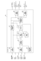
- FIG. 2 is a block diagram of an example of a functional configuration of a controller in FIG. 1
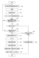
- FIG. 6 is a flowchart of an example of processing for storing target learning positions
- 7 is a flowchart of an example of processing when parking assistance is performed;
- the host vehicle 1 includes a parking assistance device 10 that assists parking of the host vehicle 1 at a target parking position.
- the parking assistance by the parking assistance device 10 the target travel trajectory from the current position of the own vehicle 1 to the target parking position is calculated. Then, it assists the own vehicle 1 to travel along the target travel trajectory.
- Parking assistance by the parking assistance device 10 includes various forms of assisting the own vehicle 1 to travel along the target travel trajectory.
- the parking of the own vehicle 1 may be assisted by performing automatic driving that controls the own vehicle 1 to travel along the target travel trajectory of the own vehicle 1 to the target parking position.
- the automatic driving that controls the own vehicle 1 to travel along the target travel trajectory of the own vehicle 1 to the target parking position means controlling all or part of the steering angle, driving force, and braking force of the own vehicle. This means control that automatically implements all or part of the vehicle 1 traveling along the target traveling trajectory, thereby assisting the occupant's parking operation. Parking of the own vehicle 1 may be assisted by displaying the target travel trajectory and the current position of the own vehicle 1 on a display device that can be visually recognized by the occupant of the own vehicle 1 .
- the parking assistance device 10 includes a positioning device 11, a human-machine interface 12, a shift switch 13, an external sensor 14, a vehicle sensor 15, a controller 16, a parking brake 17, a steering actuator 18a, and an accelerator actuator 18b. , including the brake actuator 18c.
- the human-machine interface is written as "HMI”
- the shift switch is written as "shift SW”.
- the positioning device 11 measures the current position of the own vehicle 1 .
- the positioning device 11 may for example comprise a Global Positioning System (GNSS) receiver.
- the GNSS receiver is, for example, a global positioning system (GPS) receiver or the like, and measures the current position of the vehicle 1 by receiving radio waves from a plurality of navigation satellites.
- the human-machine interface 12 is an interface device that exchanges information between the parking assistance device 10 and the occupant.
- the human-machine interface 12 includes a display device (for example, a display screen of a navigation system) visible to the occupant of the vehicle 1, and a speaker and buzzer for outputting warning sounds, notification sounds, and audio information.
- the human-machine interface 12 also includes an operator that receives an operation input from the passenger to the parking assistance device 10 .
- the operator may be a mechanical interface device such as a button, switch, lever, dial, or keyboard, or may be a button, switch, lever, dial, keyboard, or the like displayed on a touch panel.
- the shift switch 13 is a switch for the driver or the parking assistance device 10 to switch the shift position of the own vehicle 1 .
- the external sensor 14 detects an object within a predetermined distance range (for example, the detection area of the external sensor 14) from the own vehicle 1.
- the external sensor 14 detects the surrounding environment of the own vehicle 1, such as the relative position between the object existing around the own vehicle 1 and the own vehicle 1, the distance between the own vehicle 1 and the object, and the direction in which the object exists.
- the external sensor 14 may include, for example, a camera that captures the surrounding environment of the vehicle 1 .
- the camera may be, for example, an around-view monitor camera that captures a road surface around the vehicle 1 and generates a captured image that is converted into a bird's-eye view (around-view monitor image).
- the external sensor 14 may include a rangefinder such as a laser range finder (LRF), a radar, or a LiDAR (Light Detection and Ranging) laser radar.
- LRF laser range finder
- radar radar
- LiDAR Light Detection and Ranging
- the vehicle sensor 15 detects various information (vehicle information) obtained from the own vehicle 1.
- vehicle sensors 15 include, for example, a vehicle speed sensor that detects the running speed (vehicle speed) of the vehicle 1, a wheel speed sensor that detects the rotation speed of each tire of the vehicle 1, and acceleration (deceleration) of the vehicle 1 in three axial directions.
- a three-axis acceleration sensor (G sensor) that detects a steering angle (including a steering angle of a steering wheel or a turning angle of a steered wheel), a steering angle sensor that detects an angular velocity generated in the own vehicle 1
- a gyro sensor may include a yaw rate sensor that detects yaw rate.
- the controller 16 is an electronic control unit (ECU) that performs parking support control of the own vehicle 1 .
- Controller 16 includes a processor 20 and peripheral components such as storage device 21 .
- the processor 20 may be, for example, a CPU (Central Processing Unit) or an MPU (Micro-Processing Unit).
- the storage device 21 may include a semiconductor storage device, a magnetic storage device, an optical storage device, or the like.
- the functions of the controller 16 to be described below are implemented, for example, by the processor 20 executing a computer program stored in the storage device 21 .
- the controller 16 may be formed of dedicated hardware for executing each information processing described below.
- the steering actuator 18 a controls the steering direction and steering amount of the steering mechanism according to control signals from the controller 16 .
- the accelerator actuator 18b controls the accelerator opening of a driving device such as an engine or a driving motor according to a control signal from the controller 16.
- the brake actuator 18c operates the braking device according to a control signal from the controller 16.
- the target position of the target existing near the target parking position 30, which is the target position for parking the own vehicle 1 is stored in the storage device 21.
- the target is a feature that serves as a landmark for identifying the current position of the vehicle 1, and includes road markings (road signs, lane markings, and road markings) drawn on the road surface around the vehicle 1, road boundaries, It may be an obstacle such as a curb, guardrail, utility pole.
- the driver When the target position is stored in the storage device 21 , for example, the driver operates a “parking position learning switch” provided as an operator of the human-machine interface 12 . Then, the driver parks the own vehicle 1 at the target parking position 30 by manual operation.
- the external sensor 14 detects a target position, which is the position of a target existing in a detection area within a predetermined distance range from the external sensor 14 .
- the parking assistance device 10 detects, as a feature point, an image of a portion representing a target such as a road marking or a road boundary from an image captured by a camera, which is the external sensor 14, and uses the position of the feature point as the target position. good.
- the parking assistance device 10 also detects feature quantities of the detected feature points.
- feature points of point group information obtained by a laser range finder, radar, or LiDAR, which are external sensors 14, and their feature amounts (for example, shading and attributes of feature points) may be detected.
- feature amounts for example, shading and attributes of feature points
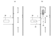
- circle plots represent feature points (that is, target positions) detected in the imaging area of the camera. While the driver manually drives the vehicle 1 at the target parking position 30, the parking assistance device 10 detects target positions detected by the external sensor 14 (for example, feature points detected from an image captured by a camera). The feature amount) is stored in the storage device 21 .
- the target position stored in the storage device 21 may be referred to as "target learning position”.
- the parking assistance device 10 also stores the relative positional relationship between the target learning position and the target parking position 30 .
- the driver may operate the human-machine interface 12 to input to the parking assistance device 10 that the current position of the vehicle 1 is the target parking position 30 .
- the parking assist system 10 obtains the relative positional relationship between the target learning position and the target parking position 30 based on the target position detected by the external sensor 14 when the own vehicle 1 is positioned at the target parking position 30.
- an image captured by the camera which is the external sensor 14 may be displayed on the display device of the human-machine interface 12, and the driver may specify the position of the target parking position 30 on the captured image.
- the parking assistance device 10 obtains the relative positional relationship between the target learning position and the target parking position 30 based on the designated target parking position 30 and the target position shown in the captured image. good too.
- each target learning position and the position of the target parking position 30 are set with respect to a fixed point. It may be stored as coordinates on a point coordinate system (hereinafter referred to as "map coordinate system").
- the target learning position From the difference in the coordinates of the target learning position and the target parking position 30 in the common map coordinate system, their relative positional relationship can be obtained.
- the coordinates on the map coordinate system are stored as the target learning position
- the current position on the map coordinate system measured by the positioning device 11 when the host vehicle 1 is positioned at the target parking position 30 is stored as the target parking position 30.
- each relative position of the target parking position 30 with respect to each target learning position may be stored.
- parking assistance by the parking assistance device 10 can be used. Please refer to FIG.
- the parking assistance device 10 determines whether or not the distance between the own vehicle 1 and the target parking position 30 is equal to or less than the first predetermined distance.
- the parking assistance device 10 determines whether or not the driver has performed a shift operation for switching between forward and backward movement of the vehicle 1 .
- FIG. 2(b) shows an example in which the own vehicle turns at the turning point 31.
- steering may include both switching from forward to reverse and switching from reverse to forward.
- the parking assistance device 10 switches over. It may be determined that a shift operation for is performed.
- the parking assistance device 10 also determines whether or not the driver has operated a “parking assistance activation switch” provided as an operator of the human-machine interface 12 .
- the parking assistance device 10 automatically performs parking assistance when the distance between the own vehicle 1 and the target parking position 30 is equal to or less than the first predetermined distance and when a shift operation for turning is performed.
- the first predetermined distance is a predetermined arbitrary distance, and is a distance appropriately set in terms of design.
- the parking assistance device 10 performs driving assistance for the own vehicle 1 when the distance between the own vehicle 1 and the target parking position 30 is equal to or less than the first predetermined distance and the parking assistance start switch is operated.
- the driving assistance of the own vehicle 1 is performed.
- the conditions for implementing the driving assistance are not limited to this.
- the distance between the own vehicle 1 and the target parking position 30 is less than the first predetermined distance and the hazard lamp is turned on, or when the distance between the own vehicle 1 and the target parking position 30 is less than the first predetermined distance and the vehicle
- the driving support for the host vehicle 1 may be implemented when the vehicle has stopped.
- the driving assistance of the vehicle 1 may be performed.
- the external sensor 14 detects the target position, which is the position of the target existing in the detection area of the external sensor 14 .
- a triangular plot indicates the target position detected by the external sensor 14 when the parking assistance is performed.
- the detection of the target position by the external sensor 14 may be always performed regardless of the shift operation or the operation of the parking assist start switch, and the detection timing of the target position by the external sensor 14 is not limited.
- the parking assistance device 10 matches each target position (triangular plot) detected by the external sensor 14 with the target learning position (circular plot in FIG. Target positions detected for targets are associated with each other.
- the parking assistance device 10 calculates the relative positional relationship between each target position (triangular plot) detected by the external sensor 14 and the own vehicle 1, and the target object associated with these target positions (triangular plot). Based on the relative positional relationship between the learned position (circle plot) and the target parking position 30, the relative positional relationship between the current position of the vehicle 1 and the target parking position 30 is calculated.
- the parking assistance device 10 may calculate the position of the target parking position 30 on a coordinate system based on the current position of the own vehicle 1 (hereinafter referred to as "vehicle coordinate system").
- the target parking position 30 in the map coordinate system may be transformed into the target parking position 30 in the vehicle coordinate system.
- the current position of the own vehicle 1 on the map coordinate system is obtained,
- the relative positional relationship between the current position of the vehicle 1 and the target parking position 30 may be calculated from the difference between the coordinates of the vehicle 1 and the target parking position 30 in the map coordinate system.
- the parking assist device 10 follows a target travel trajectory from the current position of the own vehicle 1 to the target parking position 30 via a turnaround position 31.
- the trajectory 32 from the turning point 31 to the target parking position 30 is calculated as the target travel trajectory.
- the position of the own vehicle 1 at the time when the parking assistance is started by operating the parking assistance activation switch is the position 33 near the target parking position 30, a track 34 which advances from the position 33 to the turnover position 31, A trajectory 32 from the turnover position 31 to the target parking position 30 is calculated as a target travel trajectory.
- the "target traveling trajectory leading to the target parking position via the turn-over position” includes a target traveling trajectory 32 starting from the turning-over position 31 and leading to the target parking position 30, It includes both target travel trajectories 34 , 32 turning at 31 to target parking position 30 .
- the parking assistance device 10 performs parking assistance control of the own vehicle 1 based on the calculated target travel trajectory.
- the own vehicle 1 may be controlled (automatically driven) so as to travel along the calculated target travel trajectory, and the target travel trajectory is displayed on the display device of the human-machine interface 12. good too.
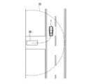
- the parking assistance device 10 detects that the vehicle 1 has left the target parking position 30 as shown in FIG. or until a predetermined time elapses after starting the vehicle, the parking assist control is suppressed.
- the second predetermined distance is an arbitrary predetermined distance, similar to the first predetermined distance, and is a distance that is appropriately set in terms of design.
- the predetermined predetermined time is also an arbitrary time, and is a time that is appropriately set in terms of design. It should be noted that the predetermined predetermined time is preferably set in consideration of the time from when the vehicle 1 departs from the target parking position 30 to when it travels the second predetermined distance. As a result, it is possible to achieve both the convenience of automatically starting parking assistance when the host vehicle approaches the parking space and the prevention of execution of parking assistance unintentional by the driver immediately after the vehicle departs from the parking space.
- the controller 16 includes a human-machine interface control section (hereinafter referred to as "HMI control section") 40, a parking assistance control section 41, an image conversion section 42, a self-position calculation section 43, a feature point detection section 44, a map generation section 45, a matching 47 , target trajectory generator 48 , steering controller 49 , and vehicle speed controller 50 .
- HMI control section human-machine interface control section
- the HMI control unit 40 outputs a map generation command to the storage device 21 to store the target learning position to the map generation unit 45 .
- the HMI control unit 40 also determines whether or not the driver has performed a shift operation for steering, and outputs the determination result to the parking assistance control unit 41 . Further, when it detects that the parking assistance start switch of the human-machine interface 12 has been operated by the driver, it outputs the detection result to the parking assistance control section 41 .
- the parking support control unit 41 determines whether or not the distance between the vehicle 1 and the target parking position 30 is equal to or less than the first predetermined distance. For example, the parking assistance control unit 41 determines whether or not the distance between the vehicle 1 and the target parking position 30 is less than or equal to the first predetermined distance based on the current position of the vehicle 1 measured by the positioning device 11. you can Further, for example, the feature amount of the target near the target parking position 30 is stored in advance, and based on whether or not the external sensor 14 detects a target having a similar feature amount, the host vehicle 1 and the target parking position 30 are determined. is less than or equal to the first predetermined distance.
- the detection range of the external sensor 14 is set to the range of the first predetermined distance from the own vehicle, and a feature amount similar to a target near the target parking position 30 is detected, the distance between the own vehicle 1 and the target parking position 30 is detected. It may be determined that the distance is less than or equal to the first predetermined distance.
- the parking assistance control unit 41 determines whether a predetermined parking assistance permission condition is satisfied. determine whether or not The parking assistance permission condition may be, for example, a condition that a predetermined time or more has passed since the vehicle 1 started from the target parking position 30 . Instead of or in addition to this, the parking assistance permission condition is that the distance between the current position of the vehicle 1 and the target parking position 30 after the vehicle 1 departs from the target parking position 30 is a first predetermined distance or less. may be a condition that the second predetermined distance is exceeded. When the parking assistance permission condition is satisfied, the parking assistance control unit 41 starts parking assistance control.
- the parking support control unit 41 starts parking support control. .
- the parking support control unit 41 starts parking support control when the HMI control unit 40 detects the operation of the parking support activation switch, but the present invention is not limited to this.
- the parking support control unit 41 may start parking support control. Further, the parking support control unit 41 may detect only one of the shift operation and the operation of the parking support activation switch, and start parking support control when the parking support permission condition is satisfied.
- the parking support control unit 41 outputs a parking position calculation command to the matching unit 47 to calculate the position of the target parking position 30 in the vehicle coordinate system. Also, based on the calculated target parking position 30, a target travel trajectory from the current position of the vehicle 1 to the target parking position 30 and a target vehicle speed profile along which the vehicle 1 travels along the target travel trajectory are calculated. A travel trajectory calculation command to cause the target trajectory to be generated is output to the target trajectory generation unit 48 .
- the target trajectory generation unit 48 calculates a target travel trajectory from the current position of the vehicle 1 to the target parking position 30 and a target vehicle speed profile, and outputs the calculated target vehicle speed profile to the parking assistance control unit 41 .
- the target travel trajectory from the current position of the own vehicle 1 to the target parking position 30 a well-known technique employed in a generally known automatic parking system can be applied. It can be calculated by connecting the current position of the vehicle 1 to the target parking position 30 via the turning point 31 with a clothoid curve.
- the target vehicle speed profile is based on a predetermined set speed, and after accelerating from the current position of the vehicle 1 to the set speed, decelerates before the turning point 31 and stops at the turning point 31.
- the vehicle speed profile can be calculated such that the vehicle accelerates from the steering position 31 to the set speed, decelerates before the target parking position 30, and stops at the target parking position 30.
- the set speed when calculating the speed profile may be set based on the calculated curvature of the target travel trajectory so that the higher the curvature, the lower the speed.
- the parking support control unit 41 outputs information on the target travel trajectory calculated by the target trajectory generation unit 48 and the current position of the host vehicle 1 to the HMI control unit 40 . If the calculated target travel trajectory includes a turn-around like the trajectories 32 and 34 in FIG.
- the HMI control unit 40 displays the target travel trajectory, the current position of the own vehicle 1, and the position display of the turning position on the display device of the human-machine interface 12.
- the parking support control unit 41 also outputs a steering control command to the steering control unit 49 to control the steering so that the host vehicle 1 travels along the calculated target travel trajectory. It also outputs a vehicle speed control command for controlling the vehicle speed of the own vehicle 1 to the vehicle speed control unit 50 according to the calculated target vehicle speed profile.
- the parking assistance control unit 41 suppresses the parking assistance control.
- the parking support control unit 41 prohibits parking support control.
- the parking assistance control unit 41 may stop outputting the parking position calculation command, the traveling track calculation command, the steering control command, and the vehicle speed control command.
- parking assistance for controlling the vehicle 1 to travel along the target travel path to the target parking position is prohibited.
- driving support that displays the target travel trajectory and the current position of the vehicle 1 on the display device may be prohibited.
- the parking assist control unit 41 may suppress the parking assist control by limiting the vehicle speed of the host vehicle 1 controlled by the vehicle speed control unit 50 to be lower than the calculated target vehicle speed profile.
- the parking assistance control unit 41 may output to the vehicle speed control unit 50 a vehicle speed control command that makes the vehicle speed of the own vehicle 1 lower than the target vehicle speed profile.
- the maximum speed in the calculated target vehicle speed profile may be limited to a speed lower than a predetermined set speed, and a vehicle speed control command based on the target vehicle speed profile with the limited maximum speed may be output to the vehicle speed control unit 50 . That is, when the parking assistance permitting condition is not satisfied, the moving speed (vehicle speed) of the own vehicle 1 when traveling to the target parking position should be reduced compared to when the parking assistance permitting condition is satisfied.
- the image conversion unit 42 converts the image captured by the camera of the external sensor 14 into a bird's eye image (around view monitor image) viewed from a virtual viewpoint right above the own vehicle 1 as shown in FIGS. 2(a) and 2(b). Convert to Hereinafter, the bird's-eye view image converted by the image conversion unit 42 may be referred to as a "surrounding image".
- FIG. 2(a) is a surrounding image when the target object learning position is stored in the storage device 21, and
- FIG. 2(b) is a surrounding image when the parking assist control is performed.
- the image conversion unit 42 generates surrounding images at predetermined intervals. For example, the image conversion unit 42 may generate a surrounding image each time the own vehicle 1 travels a predetermined distance (for example, 50 cm). Further, for example, a surrounding image may be generated each time the vehicle travels for a predetermined time (for example, one second). In this way, each of the surrounding images obtained when the vehicle 1 is at different positions and each of the surrounding images obtained at different times may be referred to as a "frame".
- the self-position calculator 43 calculates the current position of the vehicle 1 on the map coordinate system by dead reckoning based on the vehicle information output from the vehicle sensor 15 .
- the feature point detection unit 44 performs predetermined preprocessing such as noise removal, brightness adjustment, and edge enhancement on the surrounding image output from the image conversion unit 42 .
- the feature point detection unit 44 detects feature points and their feature amounts from the preprocessed surrounding image. For example, the feature point detection unit 44 may detect feature points and feature amounts using a FAST detector or a FREAK descriptor.
- the feature points detected when storing target learning positions in the storage device 21 are indicated by circular plots in FIG. 2(a). Further, feature points detected when the parking assist control is performed are indicated by triangular plots in FIG. 2(b).
- the feature point detection unit 44 extracts common feature points common to two different frames. By extracting common feature points, it is possible to remove feature points from which three-dimensional objects, raindrops, shadows of the vehicle, and moving objects are detected.
- the feature point detection unit 44 synchronizes the feature point extracted as the common feature point with the current position of the own vehicle 1 received from the self-position calculation unit 43 when the surrounding image is acquired, and matches it with the map generation unit 45. Output to unit 47 .
- the map generation unit 45 receives a map generation command from the HMI control unit 40 .
- the map generation unit 45 generates feature points including the feature points output from the feature point detection unit 44, the current position of the vehicle 1 synchronized therewith, and the feature amounts of the feature points.
- the information is stored in the storage device 21 as target object learning positions, and map data 46 is generated. Based on the current position of the vehicle 1 synchronized with the feature point, the position of the feature point in the map coordinate system may be calculated and stored as feature point information.
- the map generator 45 when the driver operates the human-machine interface 12 to input to the parking assistance device 10 that the current position of the vehicle 1 is the target parking position 30, the map generator 45 generates the map coordinate system of the vehicle 1.
- the above current position is received from the positioning device 11 or the self-position calculator 43 and stored in the map data 46 as the target parking position 30 . That is, the relative positional relationship between the target parking position 30 and a plurality of feature points is stored as map data.
- the contact unit 47 receives a parking position calculation command from the parking support control unit 41 .
- the matching unit 47 acquires the feature point information (circular plot in FIG. 2A) stored as the target object learning position in the map data 46, and the camera of the external sensor 14 when the parking assistance is performed. is matched with the feature point information (triangular plot in FIG. 2B) output from the feature point detection unit 44 from the captured image output by , and the feature point information detected for the same target are associated with each other.
- the matching unit 47 may remove feature points that do not match the two-dimensional affine transformation as outliers among the feature points that are associated with each other.
- a RANSAC Random Sample Consensus
- feature points that do not match feature amounts such as shading and attributes may be removed.
- the matching unit 47 is based on the relative positional relationship between the feature points (triangular plots) at the time of parking assistance and the own vehicle 1, and the feature points (circular plots) of the map data 46 associated with these feature points (triangular plots). plot) and the target parking position 30, the relative positional relationship between the current position of the vehicle 1 and the target parking position 30 is calculated.
- a feature point detected during parking assistance is represented by (x i , y i ), and the map data 46 associated with the feature point (x i , y i ) is stored as a target learning position.
- (x mi , y mi ) (i 1 to N).
- the matching unit 47 calculates an affine transformation matrix M affine using the following equation based on the method of least squares.
- a column vector (a 1 , a 2 , a 3 , a 4 ) T may be calculated as follows using the weighted least squares method.
- the matching unit 47 converts the position (targetx m , targety m ) of the target parking position 30 on the map coordinate system stored in the map data 46 into a position (targetx, targety) on the vehicle coordinate system using the following equation.
- the target trajectory generation unit 48 When the target trajectory generation unit 48 receives a travel trajectory calculation command from the parking support control unit 41, the target trajectory generation unit 48 moves from the current position of the own vehicle 1 on the vehicle coordinate system (that is, the coordinate origin) to the target parking position 30 (targetx, targety). A target travel trajectory and a target vehicle speed profile for the vehicle 1 traveling on the target travel trajectory are calculated.
- the steering control unit 49 receives a steering control command from the parking assistance control unit 41
- the steering control unit 49 controls the steering actuator 18a so that the own vehicle 1 travels along the target travel trajectory.
- the vehicle speed control unit 50 Upon receiving the vehicle speed control command from the parking assistance control unit 41, the vehicle speed control unit 50 controls the accelerator actuator 18b and the brake actuator 18c so that the vehicle speed of the own vehicle 1 changes according to the target vehicle speed profile. As a result, the own vehicle 1 is controlled to travel along the target travel trajectory.
- the parking support control unit 41 determines whether the vehicle 1 has reached the target parking position 30 and the parking support control has been completed. When the parking support control is completed, the parking support control unit 41 operates the parking brake 17 and switches the shift position to the parking range (hereinafter referred to as "P range").
- FIG. 5 is a flowchart of an example of processing for storing target learning positions.
- the driver operates the parking position learning switch to manually park the vehicle 1 at the target parking position.
- the image conversion unit 42 acquires a surrounding image by converting an image captured by the camera of the external sensor 14 into a bird's-eye view image viewed from a virtual viewpoint right above the own vehicle 1 .
- the feature point detection unit 44 performs predetermined preprocessing such as noise removal, brightness adjustment, and edge enhancement on the surrounding image output from the image conversion unit 42 .
- the feature point detection unit 44 detects feature points from the preprocessed surrounding image.
- step S4 the feature point detection unit 44 extracts common feature points common to two different frames.
- step S5 the map generator 45 stores the feature points extracted in step S4 in the storage device 21.
- FIG. 6 is a flowchart of an example of processing when parking assistance is performed.
- the image conversion unit 42 acquires a surrounding image.
- the feature point detection unit 44 performs predetermined preprocessing on the surrounding image output from the image conversion unit 42 . Feature points are detected from the preprocessed surrounding image in step S12.
- step S13 the feature point detection unit 44 extracts common feature points common to two different frames.
- step S14 the parking assistance control unit 41 determines whether or not the distance between the host vehicle 1 and the target parking position 30 is equal to or less than the first predetermined distance. If the distance between the host vehicle 1 and the target parking position 30 is equal to or less than the first predetermined distance (step S14: Y), the process proceeds to step S15. If the distance between the own vehicle 1 and the target parking position 30 is not equal to or less than the first predetermined distance (step S14: N), the process returns to step S10.
- step S15 the parking assistance control unit 41 determines whether or not a shift operation for steering has been detected. If a shift operation for switching is detected (step S15: Y), the process proceeds to step S16. If no shift operation for switching is detected (step S15: N), the process proceeds to step S24.
- step S16 the parking assistance control unit 41 determines whether or not the parking assistance permission condition is satisfied. If the parking assistance permission condition is satisfied (step S16: Y), the process proceeds to step S17. If the parking assistance permission condition is not satisfied (step S16: N), the process proceeds to step S23.
- step S ⁇ b>17 the matching unit 47 reads feature points stored in the map data 46 as target learning positions.
- step S18 the matching unit 47 matches the feature points extracted in step S13 with the feature points read in step S17.
- step S19 the matching unit 47 calculates the target parking position 30 based on the matched feature points.
- the target trajectory generator 48 calculates a target travel trajectory from the current position of the vehicle 1 to the target parking position 30, and a target vehicle speed profile along which the vehicle 1 travels on the target travel trajectory.
- step S21 the steering control unit 49 controls the steering actuator 18a so that the vehicle 1 travels along the target travel trajectory.
- the vehicle speed control unit 50 controls the accelerator actuator 18b and the brake actuator 18c so that the vehicle speed of the own vehicle 1 changes according to the target vehicle speed profile.
- step S22 the parking support control unit 41 determines whether or not the parking support control has been completed. When the parking support control is completed, the parking support control unit 41 operates the parking brake 17 and switches the shift position to the P range. Processing then ends.
- step S16: N if the parking assistance permission condition is not satisfied in step S16 (step S16: N), the parking assistance control unit 41 suppresses parking assistance control in step S23. Processing then ends. Further, if the shift operation for turning is not detected in step S15 (step S15: N), the parking assist control unit 41 determines in step S24 whether or not the parking assist start switch has been operated by the driver. If the parking support activation switch has been operated (step S24: Y), the process proceeds to step S17 to execute parking support control. If the parking support activation switch is not operated (step S24: N), the process returns to step S10.
- the controller 16 detects the current position of the vehicle 1, that is, the current position of the vehicle 1, calculates a target travel trajectory from the vehicle 1 to the target parking position, and determines that the distance between the vehicle 1 and the target parking position is the first. It is determined whether or not the distance is less than or equal to a predetermined distance, and a condition that a predetermined time or more has passed since the vehicle 1 started from the target parking position, or a condition that the vehicle 1 has started from the target parking position and the target parking position is determined.
- the distance between the self-position and the target parking position satisfies a parking assistance permission condition, which is either the condition that the distance between the self-position and the target parking position exceeds a second predetermined distance that is less than or equal to the first predetermined distance.
- a parking assistance permission condition which is either the condition that the distance between the self-position and the target parking position exceeds a second predetermined distance that is less than or equal to the first predetermined distance.
- Parking assistance control may be performed when the parking assistance permission condition is satisfied and the position of the shift lever is in the reverse range. This makes it possible to more appropriately prevent parking assist control that is not intended by the driver.
- the controller 16 may perform parking assist control by controlling the own vehicle 1 to travel along the target travel trajectory.
- the parking support control may be suppressed by reducing the speed of the own vehicle 1 traveling along the target travel trajectory compared to when the parking support permission conditions are satisfied.
- the driver can stop the continuation of the unintended parking support control by, for example, operating the brake at a stage when the vehicle travel distance by the parking support control is short. can.
- parking support control may be prohibited when the parking support permission conditions are not satisfied. As a result, parking assistance control that is not intended by the driver can be suppressed.
- the controller 16 may perform parking assistance control by displaying the target travel trajectory and the position of the own vehicle 1 on a display device that is visible to the occupant. If the conditions for permitting parking assistance are not met, displaying the target travel trajectory and the position of the vehicle 1 on the display device may be prohibited. As a result, parking assistance control that is not intended by the driver can be suppressed.
Landscapes
- Engineering & Computer Science (AREA)
- Automation & Control Theory (AREA)
- Transportation (AREA)
- Mechanical Engineering (AREA)
- Human Computer Interaction (AREA)
- Chemical & Material Sciences (AREA)
- Combustion & Propulsion (AREA)
- Control Of Driving Devices And Active Controlling Of Vehicle (AREA)
- Traffic Control Systems (AREA)
- Control Of Transmission Device (AREA)
- Steering Control In Accordance With Driving Conditions (AREA)
Abstract
Priority Applications (6)
| Application Number | Priority Date | Filing Date | Title |
|---|---|---|---|
| JP2023538205A JP7491476B2 (ja) | 2021-07-30 | 2021-07-30 | 駐車支援方法及び駐車支援装置 |
| PCT/JP2021/028509 WO2023007749A1 (fr) | 2021-07-30 | 2021-07-30 | Procédé d'aide au stationnement et dispositif d'aide au stationnement |
| EP21951134.2A EP4378777A4 (fr) | 2021-07-30 | 2021-07-30 | Procédé d'aide au stationnement et dispositif d'aide au stationnement |
| CN202180100739.8A CN117677553B (zh) | 2021-07-30 | 2021-07-30 | 驻车辅助方法以及驻车辅助装置 |
| MX2024001345A MX2024001345A (es) | 2021-07-30 | 2021-07-30 | Metodo de asistencia al estacionamiento y dispositivo de asistencia al estacionamiento. |
| US18/578,758 US12214777B2 (en) | 2021-07-30 | 2021-07-30 | Parking assist method and parking assist device |
Applications Claiming Priority (1)
| Application Number | Priority Date | Filing Date | Title |
|---|---|---|---|
| PCT/JP2021/028509 WO2023007749A1 (fr) | 2021-07-30 | 2021-07-30 | Procédé d'aide au stationnement et dispositif d'aide au stationnement |
Publications (1)
| Publication Number | Publication Date |
|---|---|
| WO2023007749A1 true WO2023007749A1 (fr) | 2023-02-02 |
Family
ID=85086521
Family Applications (1)
| Application Number | Title | Priority Date | Filing Date |
|---|---|---|---|
| PCT/JP2021/028509 Ceased WO2023007749A1 (fr) | 2021-07-30 | 2021-07-30 | Procédé d'aide au stationnement et dispositif d'aide au stationnement |
Country Status (6)
| Country | Link |
|---|---|
| US (1) | US12214777B2 (fr) |
| EP (1) | EP4378777A4 (fr) |
| JP (1) | JP7491476B2 (fr) |
| CN (1) | CN117677553B (fr) |
| MX (1) | MX2024001345A (fr) |
| WO (1) | WO2023007749A1 (fr) |
Cited By (1)
| Publication number | Priority date | Publication date | Assignee | Title |
|---|---|---|---|---|
| WO2026042256A1 (fr) * | 2024-08-23 | 2026-02-26 | 日産自動車株式会社 | Procédé de commande de stationnement/arrêt, dispositif de commande de stationnement/arrêt et système de commande de stationnement/arrêt |
Families Citing this family (1)
| Publication number | Priority date | Publication date | Assignee | Title |
|---|---|---|---|---|
| JP7743726B2 (ja) * | 2021-08-02 | 2025-09-25 | 日産自動車株式会社 | 駐車支援方法及び駐車支援装置 |
Citations (3)
| Publication number | Priority date | Publication date | Assignee | Title |
|---|---|---|---|---|
| JP2001106115A (ja) * | 1999-10-04 | 2001-04-17 | Yazaki Corp | 駐車支援システムにおける指示装置及びその指示プログラムを記録したコンピュータ読み取り可能な記録媒体 |
| JP2004330891A (ja) * | 2003-05-08 | 2004-11-25 | Fujitsu Ten Ltd | 利便性向上装置 |
| WO2017072941A1 (fr) | 2015-10-30 | 2017-05-04 | 三菱電機株式会社 | Dispositif d'aide au stationnement et procédé d'aide au stationnement |
Family Cites Families (6)
| Publication number | Priority date | Publication date | Assignee | Title |
|---|---|---|---|---|
| JP5182545B2 (ja) * | 2007-05-16 | 2013-04-17 | アイシン精機株式会社 | 駐車支援装置 |
| JP5212748B2 (ja) * | 2010-09-29 | 2013-06-19 | アイシン精機株式会社 | 駐車支援装置 |
| WO2014091613A1 (fr) | 2012-12-13 | 2014-06-19 | トヨタ自動車株式会社 | Dispositif d'aide au stationnement |
| JP7120036B2 (ja) | 2019-01-16 | 2022-08-17 | トヨタ自動車株式会社 | 自動駐車管理装置 |
| JP2021095113A (ja) | 2019-06-24 | 2021-06-24 | 本田技研工業株式会社 | 駐車支援システム |
| JP7247850B2 (ja) | 2019-10-11 | 2023-03-29 | トヨタ自動車株式会社 | 駐車支援装置 |
-
2021
- 2021-07-30 MX MX2024001345A patent/MX2024001345A/es unknown
- 2021-07-30 WO PCT/JP2021/028509 patent/WO2023007749A1/fr not_active Ceased
- 2021-07-30 JP JP2023538205A patent/JP7491476B2/ja active Active
- 2021-07-30 CN CN202180100739.8A patent/CN117677553B/zh active Active
- 2021-07-30 US US18/578,758 patent/US12214777B2/en active Active
- 2021-07-30 EP EP21951134.2A patent/EP4378777A4/fr not_active Withdrawn
Patent Citations (3)
| Publication number | Priority date | Publication date | Assignee | Title |
|---|---|---|---|---|
| JP2001106115A (ja) * | 1999-10-04 | 2001-04-17 | Yazaki Corp | 駐車支援システムにおける指示装置及びその指示プログラムを記録したコンピュータ読み取り可能な記録媒体 |
| JP2004330891A (ja) * | 2003-05-08 | 2004-11-25 | Fujitsu Ten Ltd | 利便性向上装置 |
| WO2017072941A1 (fr) | 2015-10-30 | 2017-05-04 | 三菱電機株式会社 | Dispositif d'aide au stationnement et procédé d'aide au stationnement |
Non-Patent Citations (1)
| Title |
|---|
| See also references of EP4378777A4 |
Cited By (1)
| Publication number | Priority date | Publication date | Assignee | Title |
|---|---|---|---|---|
| WO2026042256A1 (fr) * | 2024-08-23 | 2026-02-26 | 日産自動車株式会社 | Procédé de commande de stationnement/arrêt, dispositif de commande de stationnement/arrêt et système de commande de stationnement/arrêt |
Also Published As
| Publication number | Publication date |
|---|---|
| CN117677553A (zh) | 2024-03-08 |
| US20240367642A1 (en) | 2024-11-07 |
| JPWO2023007749A1 (fr) | 2023-02-02 |
| EP4378777A1 (fr) | 2024-06-05 |
| EP4378777A4 (fr) | 2024-10-09 |
| CN117677553B (zh) | 2024-12-06 |
| MX2024001345A (es) | 2024-02-15 |
| US12214777B2 (en) | 2025-02-04 |
| JP7491476B2 (ja) | 2024-05-28 |
Similar Documents
| Publication | Publication Date | Title |
|---|---|---|
| JP7448403B2 (ja) | 駐車枠認識システム、及び、駐車枠認識システムを備えた駐車支援システム | |
| JP7816484B2 (ja) | 駐車支援方法及び駐車支援装置 | |
| JP7491476B2 (ja) | 駐車支援方法及び駐車支援装置 | |
| WO2023100230A1 (fr) | Procédé et dispositif d'aide au stationnement | |
| JP2007309670A (ja) | 車両位置検出装置 | |
| JP7743726B2 (ja) | 駐車支援方法及び駐車支援装置 | |
| WO2024157443A1 (fr) | Procédé et dispositif d'aide au stationnement | |
| JP7771820B2 (ja) | 駐車支援方法及び駐車支援装置 | |
| JP7715204B2 (ja) | 駐車支援方法及び駐車支援装置 | |
| JP7761147B2 (ja) | 駐車支援方法及び駐車支援装置 | |
| WO2024157441A1 (fr) | Procédé d'aide au stationnement et dispositif d'aide au stationnement | |
| JP7608960B2 (ja) | 駐車支援方法及び駐車支援装置 | |
| WO2024157442A1 (fr) | Procédé d'aide au stationnement et dispositif d'aide au stationnement | |
| JP7616419B2 (ja) | 駐車支援方法及び駐車支援装置 | |
| WO2023119656A1 (fr) | Procédé d'aide au stationnement et dispositif d'aide au stationnement | |
| WO2024157449A1 (fr) | Procédé d'aide au stationnement et dispositif d'aide au stationnement | |
| WO2024184974A1 (fr) | Procédé d'aide au stationnement et dispositif d'aide au stationnement | |
| WO2024013807A1 (fr) | Procédé et dispositif d'aide au stationnement | |
| WO2024157444A1 (fr) | Procédé d'aide au stationnement et dispositif d'aide au stationnement | |
| WO2025088729A1 (fr) | Procédé d'aide au stationnement et dispositif d'aide au stationnement | |
| WO2025257900A1 (fr) | Procédé d'aide au stationnement et dispositif d'aide au stationnement | |
| WO2025088730A1 (fr) | Procédé d'aide au stationnement et dispositif d'aide au stationnement | |
| WO2024157461A1 (fr) | Procédé d'aide au stationnement et dispositif d'aide au stationnement | |
| WO2024157460A1 (fr) | Procédé d'aide au stationnement et dispositif d'aide au stationnement | |
| WO2026028346A1 (fr) | Procédé d'aide au stationnement, dispositif d'aide au stationnement et système d'aide au stationnement |
Legal Events
| Date | Code | Title | Description |
|---|---|---|---|
| 121 | Ep: the epo has been informed by wipo that ep was designated in this application |
Ref document number: 21951134 Country of ref document: EP Kind code of ref document: A1 |
|
| WWE | Wipo information: entry into national phase |
Ref document number: 2023538205 Country of ref document: JP |
|
| WWE | Wipo information: entry into national phase |
Ref document number: 202180100739.8 Country of ref document: CN |
|
| WWE | Wipo information: entry into national phase |
Ref document number: MX/A/2024/001345 Country of ref document: MX |
|
| REG | Reference to national code |
Ref country code: BR Ref legal event code: B01A Ref document number: 112024001676 Country of ref document: BR |
|
| WWE | Wipo information: entry into national phase |
Ref document number: 202447012840 Country of ref document: IN |
|
| WWE | Wipo information: entry into national phase |
Ref document number: 2021951134 Country of ref document: EP |
|
| NENP | Non-entry into the national phase |
Ref country code: DE |
|
| ENP | Entry into the national phase |
Ref document number: 2021951134 Country of ref document: EP Effective date: 20240229 |
|
| ENP | Entry into the national phase |
Ref document number: 112024001676 Country of ref document: BR Kind code of ref document: A2 Effective date: 20240126 |
|
| WWW | Wipo information: withdrawn in national office |
Ref document number: 2021951134 Country of ref document: EP |