WO2023007749A1 - 駐車支援方法及び駐車支援装置 - Google Patents
駐車支援方法及び駐車支援装置 Download PDFInfo
- Publication number
- WO2023007749A1 WO2023007749A1 PCT/JP2021/028509 JP2021028509W WO2023007749A1 WO 2023007749 A1 WO2023007749 A1 WO 2023007749A1 JP 2021028509 W JP2021028509 W JP 2021028509W WO 2023007749 A1 WO2023007749 A1 WO 2023007749A1
- Authority
- WO
- WIPO (PCT)
- Prior art keywords
- parking
- target
- vehicle
- parking assistance
- distance
- Prior art date
- Legal status (The legal status is an assumption and is not a legal conclusion. Google has not performed a legal analysis and makes no representation as to the accuracy of the status listed.)
- Ceased
Links
Images


Classifications
-
- B—PERFORMING OPERATIONS; TRANSPORTING
- B62—LAND VEHICLES FOR TRAVELLING OTHERWISE THAN ON RAILS
- B62D—MOTOR VEHICLES; TRAILERS
- B62D15/00—Steering not otherwise provided for
- B62D15/02—Steering position indicators ; Steering position determination; Steering aids
- B62D15/027—Parking aids, e.g. instruction means
- B62D15/0285—Parking performed automatically
-
- B—PERFORMING OPERATIONS; TRANSPORTING
- B60—VEHICLES IN GENERAL
- B60W—CONJOINT CONTROL OF VEHICLE SUB-UNITS OF DIFFERENT TYPE OR DIFFERENT FUNCTION; CONTROL SYSTEMS SPECIALLY ADAPTED FOR HYBRID VEHICLES; ROAD VEHICLE DRIVE CONTROL SYSTEMS FOR PURPOSES NOT RELATED TO THE CONTROL OF A PARTICULAR SUB-UNIT
- B60W30/00—Purposes of road vehicle drive control systems not related to the control of a particular sub-unit, e.g. of systems using conjoint control of vehicle sub-units
- B60W30/06—Automatic manoeuvring for parking
-
- B—PERFORMING OPERATIONS; TRANSPORTING
- B60—VEHICLES IN GENERAL
- B60W—CONJOINT CONTROL OF VEHICLE SUB-UNITS OF DIFFERENT TYPE OR DIFFERENT FUNCTION; CONTROL SYSTEMS SPECIALLY ADAPTED FOR HYBRID VEHICLES; ROAD VEHICLE DRIVE CONTROL SYSTEMS FOR PURPOSES NOT RELATED TO THE CONTROL OF A PARTICULAR SUB-UNIT
- B60W30/00—Purposes of road vehicle drive control systems not related to the control of a particular sub-unit, e.g. of systems using conjoint control of vehicle sub-units
- B60W30/14—Adaptive cruise control
- B60W30/143—Speed control
-
- B—PERFORMING OPERATIONS; TRANSPORTING
- B60—VEHICLES IN GENERAL
- B60W—CONJOINT CONTROL OF VEHICLE SUB-UNITS OF DIFFERENT TYPE OR DIFFERENT FUNCTION; CONTROL SYSTEMS SPECIALLY ADAPTED FOR HYBRID VEHICLES; ROAD VEHICLE DRIVE CONTROL SYSTEMS FOR PURPOSES NOT RELATED TO THE CONTROL OF A PARTICULAR SUB-UNIT
- B60W50/00—Details of control systems for road vehicle drive control not related to the control of a particular sub-unit, e.g. process diagnostic or vehicle driver interfaces
- B60W50/08—Interaction between the driver and the control system
-
- B—PERFORMING OPERATIONS; TRANSPORTING
- B60—VEHICLES IN GENERAL
- B60W—CONJOINT CONTROL OF VEHICLE SUB-UNITS OF DIFFERENT TYPE OR DIFFERENT FUNCTION; CONTROL SYSTEMS SPECIALLY ADAPTED FOR HYBRID VEHICLES; ROAD VEHICLE DRIVE CONTROL SYSTEMS FOR PURPOSES NOT RELATED TO THE CONTROL OF A PARTICULAR SUB-UNIT
- B60W50/00—Details of control systems for road vehicle drive control not related to the control of a particular sub-unit, e.g. process diagnostic or vehicle driver interfaces
- B60W50/08—Interaction between the driver and the control system
- B60W50/14—Means for informing the driver, warning the driver or prompting a driver intervention
-
- B—PERFORMING OPERATIONS; TRANSPORTING
- B60—VEHICLES IN GENERAL
- B60W—CONJOINT CONTROL OF VEHICLE SUB-UNITS OF DIFFERENT TYPE OR DIFFERENT FUNCTION; CONTROL SYSTEMS SPECIALLY ADAPTED FOR HYBRID VEHICLES; ROAD VEHICLE DRIVE CONTROL SYSTEMS FOR PURPOSES NOT RELATED TO THE CONTROL OF A PARTICULAR SUB-UNIT
- B60W50/00—Details of control systems for road vehicle drive control not related to the control of a particular sub-unit, e.g. process diagnostic or vehicle driver interfaces
- B60W50/08—Interaction between the driver and the control system
- B60W50/14—Means for informing the driver, warning the driver or prompting a driver intervention
- B60W2050/146—Display means
-
- B—PERFORMING OPERATIONS; TRANSPORTING
- B60—VEHICLES IN GENERAL
- B60W—CONJOINT CONTROL OF VEHICLE SUB-UNITS OF DIFFERENT TYPE OR DIFFERENT FUNCTION; CONTROL SYSTEMS SPECIALLY ADAPTED FOR HYBRID VEHICLES; ROAD VEHICLE DRIVE CONTROL SYSTEMS FOR PURPOSES NOT RELATED TO THE CONTROL OF A PARTICULAR SUB-UNIT
- B60W2540/00—Input parameters relating to occupants
- B60W2540/16—Ratio selector position
-
- B—PERFORMING OPERATIONS; TRANSPORTING
- B60—VEHICLES IN GENERAL
- B60W—CONJOINT CONTROL OF VEHICLE SUB-UNITS OF DIFFERENT TYPE OR DIFFERENT FUNCTION; CONTROL SYSTEMS SPECIALLY ADAPTED FOR HYBRID VEHICLES; ROAD VEHICLE DRIVE CONTROL SYSTEMS FOR PURPOSES NOT RELATED TO THE CONTROL OF A PARTICULAR SUB-UNIT
- B60W2554/00—Input parameters relating to objects
- B60W2554/80—Spatial relation or speed relative to objects
- B60W2554/802—Longitudinal distance
-
- B—PERFORMING OPERATIONS; TRANSPORTING
- B60—VEHICLES IN GENERAL
- B60W—CONJOINT CONTROL OF VEHICLE SUB-UNITS OF DIFFERENT TYPE OR DIFFERENT FUNCTION; CONTROL SYSTEMS SPECIALLY ADAPTED FOR HYBRID VEHICLES; ROAD VEHICLE DRIVE CONTROL SYSTEMS FOR PURPOSES NOT RELATED TO THE CONTROL OF A PARTICULAR SUB-UNIT
- B60W2556/00—Input parameters relating to data
- B60W2556/45—External transmission of data to or from the vehicle
- B60W2556/50—External transmission of data to or from the vehicle of positioning data, e.g. GPS [Global Positioning System] data
-
- B—PERFORMING OPERATIONS; TRANSPORTING
- B60—VEHICLES IN GENERAL
- B60W—CONJOINT CONTROL OF VEHICLE SUB-UNITS OF DIFFERENT TYPE OR DIFFERENT FUNCTION; CONTROL SYSTEMS SPECIALLY ADAPTED FOR HYBRID VEHICLES; ROAD VEHICLE DRIVE CONTROL SYSTEMS FOR PURPOSES NOT RELATED TO THE CONTROL OF A PARTICULAR SUB-UNIT
- B60W2720/00—Output or target parameters relating to overall vehicle dynamics
- B60W2720/10—Longitudinal speed
Definitions
- the present invention relates to a parking assistance method and a parking assistance device.
- Patent Document 1 describes a parking assistance device that automatically starts parking assistance when it is determined that the vehicle is approaching a parking space.
- An object of the present invention is to achieve both the convenience of automatically starting parking assistance when one's own vehicle approaches a parking space and the prevention of execution of parking assistance not intended by the driver immediately after starting from the parking space.
- the parking assistance method of one aspect of the present invention it is determined whether or not the distance between the self-position, which is the current position of the vehicle, and the target parking position is equal to or less than a first predetermined distance, and the vehicle is positioned at the target parking position. or the distance between the self-position and the target parking position after the vehicle departed from the target parking position exceeds a second predetermined distance that is less than or equal to the first predetermined distance. If the distance between the self position and the target parking position is equal to or less than the first predetermined distance and the parking support permission condition is satisfied.
- parking assistance control of the own vehicle based on the target travel trajectory is performed, and parking assistance is performed when the parking assistance permission conditions are not satisfied even if the distance between the self-position and the target parking position is equal to or less than the first predetermined distance. Suppress control.
- FIG. 1 is an explanatory diagram of an example of a driving support method according to an embodiment
- FIG. 2 is a block diagram of an example of a functional configuration of a controller in FIG. 1
- FIG. 6 is a flowchart of an example of processing for storing target learning positions
- 7 is a flowchart of an example of processing when parking assistance is performed;
- the host vehicle 1 includes a parking assistance device 10 that assists parking of the host vehicle 1 at a target parking position.
- the parking assistance by the parking assistance device 10 the target travel trajectory from the current position of the own vehicle 1 to the target parking position is calculated. Then, it assists the own vehicle 1 to travel along the target travel trajectory.
- Parking assistance by the parking assistance device 10 includes various forms of assisting the own vehicle 1 to travel along the target travel trajectory.
- the parking of the own vehicle 1 may be assisted by performing automatic driving that controls the own vehicle 1 to travel along the target travel trajectory of the own vehicle 1 to the target parking position.
- the automatic driving that controls the own vehicle 1 to travel along the target travel trajectory of the own vehicle 1 to the target parking position means controlling all or part of the steering angle, driving force, and braking force of the own vehicle. This means control that automatically implements all or part of the vehicle 1 traveling along the target traveling trajectory, thereby assisting the occupant's parking operation. Parking of the own vehicle 1 may be assisted by displaying the target travel trajectory and the current position of the own vehicle 1 on a display device that can be visually recognized by the occupant of the own vehicle 1 .
- the parking assistance device 10 includes a positioning device 11, a human-machine interface 12, a shift switch 13, an external sensor 14, a vehicle sensor 15, a controller 16, a parking brake 17, a steering actuator 18a, and an accelerator actuator 18b. , including the brake actuator 18c.
- the human-machine interface is written as "HMI”
- the shift switch is written as "shift SW”.
- the positioning device 11 measures the current position of the own vehicle 1 .
- the positioning device 11 may for example comprise a Global Positioning System (GNSS) receiver.
- the GNSS receiver is, for example, a global positioning system (GPS) receiver or the like, and measures the current position of the vehicle 1 by receiving radio waves from a plurality of navigation satellites.
- the human-machine interface 12 is an interface device that exchanges information between the parking assistance device 10 and the occupant.
- the human-machine interface 12 includes a display device (for example, a display screen of a navigation system) visible to the occupant of the vehicle 1, and a speaker and buzzer for outputting warning sounds, notification sounds, and audio information.
- the human-machine interface 12 also includes an operator that receives an operation input from the passenger to the parking assistance device 10 .
- the operator may be a mechanical interface device such as a button, switch, lever, dial, or keyboard, or may be a button, switch, lever, dial, keyboard, or the like displayed on a touch panel.
- the shift switch 13 is a switch for the driver or the parking assistance device 10 to switch the shift position of the own vehicle 1 .
- the external sensor 14 detects an object within a predetermined distance range (for example, the detection area of the external sensor 14) from the own vehicle 1.
- the external sensor 14 detects the surrounding environment of the own vehicle 1, such as the relative position between the object existing around the own vehicle 1 and the own vehicle 1, the distance between the own vehicle 1 and the object, and the direction in which the object exists.
- the external sensor 14 may include, for example, a camera that captures the surrounding environment of the vehicle 1 .
- the camera may be, for example, an around-view monitor camera that captures a road surface around the vehicle 1 and generates a captured image that is converted into a bird's-eye view (around-view monitor image).
- the external sensor 14 may include a rangefinder such as a laser range finder (LRF), a radar, or a LiDAR (Light Detection and Ranging) laser radar.
- LRF laser range finder
- radar radar
- LiDAR Light Detection and Ranging
- the vehicle sensor 15 detects various information (vehicle information) obtained from the own vehicle 1.
- vehicle sensors 15 include, for example, a vehicle speed sensor that detects the running speed (vehicle speed) of the vehicle 1, a wheel speed sensor that detects the rotation speed of each tire of the vehicle 1, and acceleration (deceleration) of the vehicle 1 in three axial directions.
- a three-axis acceleration sensor (G sensor) that detects a steering angle (including a steering angle of a steering wheel or a turning angle of a steered wheel), a steering angle sensor that detects an angular velocity generated in the own vehicle 1
- a gyro sensor may include a yaw rate sensor that detects yaw rate.
- the controller 16 is an electronic control unit (ECU) that performs parking support control of the own vehicle 1 .
- Controller 16 includes a processor 20 and peripheral components such as storage device 21 .
- the processor 20 may be, for example, a CPU (Central Processing Unit) or an MPU (Micro-Processing Unit).
- the storage device 21 may include a semiconductor storage device, a magnetic storage device, an optical storage device, or the like.
- the functions of the controller 16 to be described below are implemented, for example, by the processor 20 executing a computer program stored in the storage device 21 .
- the controller 16 may be formed of dedicated hardware for executing each information processing described below.
- the steering actuator 18 a controls the steering direction and steering amount of the steering mechanism according to control signals from the controller 16 .
- the accelerator actuator 18b controls the accelerator opening of a driving device such as an engine or a driving motor according to a control signal from the controller 16.
- the brake actuator 18c operates the braking device according to a control signal from the controller 16.
- the target position of the target existing near the target parking position 30, which is the target position for parking the own vehicle 1 is stored in the storage device 21.
- the target is a feature that serves as a landmark for identifying the current position of the vehicle 1, and includes road markings (road signs, lane markings, and road markings) drawn on the road surface around the vehicle 1, road boundaries, It may be an obstacle such as a curb, guardrail, utility pole.
- the driver When the target position is stored in the storage device 21 , for example, the driver operates a “parking position learning switch” provided as an operator of the human-machine interface 12 . Then, the driver parks the own vehicle 1 at the target parking position 30 by manual operation.
- the external sensor 14 detects a target position, which is the position of a target existing in a detection area within a predetermined distance range from the external sensor 14 .
- the parking assistance device 10 detects, as a feature point, an image of a portion representing a target such as a road marking or a road boundary from an image captured by a camera, which is the external sensor 14, and uses the position of the feature point as the target position. good.
- the parking assistance device 10 also detects feature quantities of the detected feature points.
- feature points of point group information obtained by a laser range finder, radar, or LiDAR, which are external sensors 14, and their feature amounts (for example, shading and attributes of feature points) may be detected.
- feature amounts for example, shading and attributes of feature points
- circle plots represent feature points (that is, target positions) detected in the imaging area of the camera. While the driver manually drives the vehicle 1 at the target parking position 30, the parking assistance device 10 detects target positions detected by the external sensor 14 (for example, feature points detected from an image captured by a camera). The feature amount) is stored in the storage device 21 .
- the target position stored in the storage device 21 may be referred to as "target learning position”.
- the parking assistance device 10 also stores the relative positional relationship between the target learning position and the target parking position 30 .
- the driver may operate the human-machine interface 12 to input to the parking assistance device 10 that the current position of the vehicle 1 is the target parking position 30 .
- the parking assist system 10 obtains the relative positional relationship between the target learning position and the target parking position 30 based on the target position detected by the external sensor 14 when the own vehicle 1 is positioned at the target parking position 30.
- an image captured by the camera which is the external sensor 14 may be displayed on the display device of the human-machine interface 12, and the driver may specify the position of the target parking position 30 on the captured image.
- the parking assistance device 10 obtains the relative positional relationship between the target learning position and the target parking position 30 based on the designated target parking position 30 and the target position shown in the captured image. good too.
- each target learning position and the position of the target parking position 30 are set with respect to a fixed point. It may be stored as coordinates on a point coordinate system (hereinafter referred to as "map coordinate system").
- the target learning position From the difference in the coordinates of the target learning position and the target parking position 30 in the common map coordinate system, their relative positional relationship can be obtained.
- the coordinates on the map coordinate system are stored as the target learning position
- the current position on the map coordinate system measured by the positioning device 11 when the host vehicle 1 is positioned at the target parking position 30 is stored as the target parking position 30.
- each relative position of the target parking position 30 with respect to each target learning position may be stored.
- parking assistance by the parking assistance device 10 can be used. Please refer to FIG.
- the parking assistance device 10 determines whether or not the distance between the own vehicle 1 and the target parking position 30 is equal to or less than the first predetermined distance.
- the parking assistance device 10 determines whether or not the driver has performed a shift operation for switching between forward and backward movement of the vehicle 1 .
- FIG. 2(b) shows an example in which the own vehicle turns at the turning point 31.
- steering may include both switching from forward to reverse and switching from reverse to forward.
- the parking assistance device 10 switches over. It may be determined that a shift operation for is performed.
- the parking assistance device 10 also determines whether or not the driver has operated a “parking assistance activation switch” provided as an operator of the human-machine interface 12 .
- the parking assistance device 10 automatically performs parking assistance when the distance between the own vehicle 1 and the target parking position 30 is equal to or less than the first predetermined distance and when a shift operation for turning is performed.
- the first predetermined distance is a predetermined arbitrary distance, and is a distance appropriately set in terms of design.
- the parking assistance device 10 performs driving assistance for the own vehicle 1 when the distance between the own vehicle 1 and the target parking position 30 is equal to or less than the first predetermined distance and the parking assistance start switch is operated.
- the driving assistance of the own vehicle 1 is performed.
- the conditions for implementing the driving assistance are not limited to this.
- the distance between the own vehicle 1 and the target parking position 30 is less than the first predetermined distance and the hazard lamp is turned on, or when the distance between the own vehicle 1 and the target parking position 30 is less than the first predetermined distance and the vehicle
- the driving support for the host vehicle 1 may be implemented when the vehicle has stopped.
- the driving assistance of the vehicle 1 may be performed.
- the external sensor 14 detects the target position, which is the position of the target existing in the detection area of the external sensor 14 .
- a triangular plot indicates the target position detected by the external sensor 14 when the parking assistance is performed.
- the detection of the target position by the external sensor 14 may be always performed regardless of the shift operation or the operation of the parking assist start switch, and the detection timing of the target position by the external sensor 14 is not limited.
- the parking assistance device 10 matches each target position (triangular plot) detected by the external sensor 14 with the target learning position (circular plot in FIG. Target positions detected for targets are associated with each other.
- the parking assistance device 10 calculates the relative positional relationship between each target position (triangular plot) detected by the external sensor 14 and the own vehicle 1, and the target object associated with these target positions (triangular plot). Based on the relative positional relationship between the learned position (circle plot) and the target parking position 30, the relative positional relationship between the current position of the vehicle 1 and the target parking position 30 is calculated.
- the parking assistance device 10 may calculate the position of the target parking position 30 on a coordinate system based on the current position of the own vehicle 1 (hereinafter referred to as "vehicle coordinate system").
- the target parking position 30 in the map coordinate system may be transformed into the target parking position 30 in the vehicle coordinate system.
- the current position of the own vehicle 1 on the map coordinate system is obtained,
- the relative positional relationship between the current position of the vehicle 1 and the target parking position 30 may be calculated from the difference between the coordinates of the vehicle 1 and the target parking position 30 in the map coordinate system.
- the parking assist device 10 follows a target travel trajectory from the current position of the own vehicle 1 to the target parking position 30 via a turnaround position 31.
- the trajectory 32 from the turning point 31 to the target parking position 30 is calculated as the target travel trajectory.
- the position of the own vehicle 1 at the time when the parking assistance is started by operating the parking assistance activation switch is the position 33 near the target parking position 30, a track 34 which advances from the position 33 to the turnover position 31, A trajectory 32 from the turnover position 31 to the target parking position 30 is calculated as a target travel trajectory.
- the "target traveling trajectory leading to the target parking position via the turn-over position” includes a target traveling trajectory 32 starting from the turning-over position 31 and leading to the target parking position 30, It includes both target travel trajectories 34 , 32 turning at 31 to target parking position 30 .
- the parking assistance device 10 performs parking assistance control of the own vehicle 1 based on the calculated target travel trajectory.
- the own vehicle 1 may be controlled (automatically driven) so as to travel along the calculated target travel trajectory, and the target travel trajectory is displayed on the display device of the human-machine interface 12. good too.
- the parking assistance device 10 detects that the vehicle 1 has left the target parking position 30 as shown in FIG. or until a predetermined time elapses after starting the vehicle, the parking assist control is suppressed.
- the second predetermined distance is an arbitrary predetermined distance, similar to the first predetermined distance, and is a distance that is appropriately set in terms of design.
- the predetermined predetermined time is also an arbitrary time, and is a time that is appropriately set in terms of design. It should be noted that the predetermined predetermined time is preferably set in consideration of the time from when the vehicle 1 departs from the target parking position 30 to when it travels the second predetermined distance. As a result, it is possible to achieve both the convenience of automatically starting parking assistance when the host vehicle approaches the parking space and the prevention of execution of parking assistance unintentional by the driver immediately after the vehicle departs from the parking space.
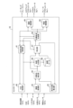
- the controller 16 includes a human-machine interface control section (hereinafter referred to as "HMI control section") 40, a parking assistance control section 41, an image conversion section 42, a self-position calculation section 43, a feature point detection section 44, a map generation section 45, a matching 47 , target trajectory generator 48 , steering controller 49 , and vehicle speed controller 50 .
- HMI control section human-machine interface control section
- the HMI control unit 40 outputs a map generation command to the storage device 21 to store the target learning position to the map generation unit 45 .
- the HMI control unit 40 also determines whether or not the driver has performed a shift operation for steering, and outputs the determination result to the parking assistance control unit 41 . Further, when it detects that the parking assistance start switch of the human-machine interface 12 has been operated by the driver, it outputs the detection result to the parking assistance control section 41 .
- the parking support control unit 41 determines whether or not the distance between the vehicle 1 and the target parking position 30 is equal to or less than the first predetermined distance. For example, the parking assistance control unit 41 determines whether or not the distance between the vehicle 1 and the target parking position 30 is less than or equal to the first predetermined distance based on the current position of the vehicle 1 measured by the positioning device 11. you can Further, for example, the feature amount of the target near the target parking position 30 is stored in advance, and based on whether or not the external sensor 14 detects a target having a similar feature amount, the host vehicle 1 and the target parking position 30 are determined. is less than or equal to the first predetermined distance.
- the detection range of the external sensor 14 is set to the range of the first predetermined distance from the own vehicle, and a feature amount similar to a target near the target parking position 30 is detected, the distance between the own vehicle 1 and the target parking position 30 is detected. It may be determined that the distance is less than or equal to the first predetermined distance.
- the parking assistance control unit 41 determines whether a predetermined parking assistance permission condition is satisfied. determine whether or not The parking assistance permission condition may be, for example, a condition that a predetermined time or more has passed since the vehicle 1 started from the target parking position 30 . Instead of or in addition to this, the parking assistance permission condition is that the distance between the current position of the vehicle 1 and the target parking position 30 after the vehicle 1 departs from the target parking position 30 is a first predetermined distance or less. may be a condition that the second predetermined distance is exceeded. When the parking assistance permission condition is satisfied, the parking assistance control unit 41 starts parking assistance control.
- the parking support control unit 41 starts parking support control. .
- the parking support control unit 41 starts parking support control when the HMI control unit 40 detects the operation of the parking support activation switch, but the present invention is not limited to this.
- the parking support control unit 41 may start parking support control. Further, the parking support control unit 41 may detect only one of the shift operation and the operation of the parking support activation switch, and start parking support control when the parking support permission condition is satisfied.
- the parking support control unit 41 outputs a parking position calculation command to the matching unit 47 to calculate the position of the target parking position 30 in the vehicle coordinate system. Also, based on the calculated target parking position 30, a target travel trajectory from the current position of the vehicle 1 to the target parking position 30 and a target vehicle speed profile along which the vehicle 1 travels along the target travel trajectory are calculated. A travel trajectory calculation command to cause the target trajectory to be generated is output to the target trajectory generation unit 48 .
- the target trajectory generation unit 48 calculates a target travel trajectory from the current position of the vehicle 1 to the target parking position 30 and a target vehicle speed profile, and outputs the calculated target vehicle speed profile to the parking assistance control unit 41 .
- the target travel trajectory from the current position of the own vehicle 1 to the target parking position 30 a well-known technique employed in a generally known automatic parking system can be applied. It can be calculated by connecting the current position of the vehicle 1 to the target parking position 30 via the turning point 31 with a clothoid curve.
- the target vehicle speed profile is based on a predetermined set speed, and after accelerating from the current position of the vehicle 1 to the set speed, decelerates before the turning point 31 and stops at the turning point 31.
- the vehicle speed profile can be calculated such that the vehicle accelerates from the steering position 31 to the set speed, decelerates before the target parking position 30, and stops at the target parking position 30.
- the set speed when calculating the speed profile may be set based on the calculated curvature of the target travel trajectory so that the higher the curvature, the lower the speed.
- the parking support control unit 41 outputs information on the target travel trajectory calculated by the target trajectory generation unit 48 and the current position of the host vehicle 1 to the HMI control unit 40 . If the calculated target travel trajectory includes a turn-around like the trajectories 32 and 34 in FIG.
- the HMI control unit 40 displays the target travel trajectory, the current position of the own vehicle 1, and the position display of the turning position on the display device of the human-machine interface 12.
- the parking support control unit 41 also outputs a steering control command to the steering control unit 49 to control the steering so that the host vehicle 1 travels along the calculated target travel trajectory. It also outputs a vehicle speed control command for controlling the vehicle speed of the own vehicle 1 to the vehicle speed control unit 50 according to the calculated target vehicle speed profile.
- the parking assistance control unit 41 suppresses the parking assistance control.
- the parking support control unit 41 prohibits parking support control.
- the parking assistance control unit 41 may stop outputting the parking position calculation command, the traveling track calculation command, the steering control command, and the vehicle speed control command.
- parking assistance for controlling the vehicle 1 to travel along the target travel path to the target parking position is prohibited.
- driving support that displays the target travel trajectory and the current position of the vehicle 1 on the display device may be prohibited.
- the parking assist control unit 41 may suppress the parking assist control by limiting the vehicle speed of the host vehicle 1 controlled by the vehicle speed control unit 50 to be lower than the calculated target vehicle speed profile.
- the parking assistance control unit 41 may output to the vehicle speed control unit 50 a vehicle speed control command that makes the vehicle speed of the own vehicle 1 lower than the target vehicle speed profile.
- the maximum speed in the calculated target vehicle speed profile may be limited to a speed lower than a predetermined set speed, and a vehicle speed control command based on the target vehicle speed profile with the limited maximum speed may be output to the vehicle speed control unit 50 . That is, when the parking assistance permitting condition is not satisfied, the moving speed (vehicle speed) of the own vehicle 1 when traveling to the target parking position should be reduced compared to when the parking assistance permitting condition is satisfied.
- the image conversion unit 42 converts the image captured by the camera of the external sensor 14 into a bird's eye image (around view monitor image) viewed from a virtual viewpoint right above the own vehicle 1 as shown in FIGS. 2(a) and 2(b). Convert to Hereinafter, the bird's-eye view image converted by the image conversion unit 42 may be referred to as a "surrounding image".
- FIG. 2(a) is a surrounding image when the target object learning position is stored in the storage device 21, and
- FIG. 2(b) is a surrounding image when the parking assist control is performed.
- the image conversion unit 42 generates surrounding images at predetermined intervals. For example, the image conversion unit 42 may generate a surrounding image each time the own vehicle 1 travels a predetermined distance (for example, 50 cm). Further, for example, a surrounding image may be generated each time the vehicle travels for a predetermined time (for example, one second). In this way, each of the surrounding images obtained when the vehicle 1 is at different positions and each of the surrounding images obtained at different times may be referred to as a "frame".
- the self-position calculator 43 calculates the current position of the vehicle 1 on the map coordinate system by dead reckoning based on the vehicle information output from the vehicle sensor 15 .
- the feature point detection unit 44 performs predetermined preprocessing such as noise removal, brightness adjustment, and edge enhancement on the surrounding image output from the image conversion unit 42 .
- the feature point detection unit 44 detects feature points and their feature amounts from the preprocessed surrounding image. For example, the feature point detection unit 44 may detect feature points and feature amounts using a FAST detector or a FREAK descriptor.
- the feature points detected when storing target learning positions in the storage device 21 are indicated by circular plots in FIG. 2(a). Further, feature points detected when the parking assist control is performed are indicated by triangular plots in FIG. 2(b).
- the feature point detection unit 44 extracts common feature points common to two different frames. By extracting common feature points, it is possible to remove feature points from which three-dimensional objects, raindrops, shadows of the vehicle, and moving objects are detected.
- the feature point detection unit 44 synchronizes the feature point extracted as the common feature point with the current position of the own vehicle 1 received from the self-position calculation unit 43 when the surrounding image is acquired, and matches it with the map generation unit 45. Output to unit 47 .
- the map generation unit 45 receives a map generation command from the HMI control unit 40 .
- the map generation unit 45 generates feature points including the feature points output from the feature point detection unit 44, the current position of the vehicle 1 synchronized therewith, and the feature amounts of the feature points.
- the information is stored in the storage device 21 as target object learning positions, and map data 46 is generated. Based on the current position of the vehicle 1 synchronized with the feature point, the position of the feature point in the map coordinate system may be calculated and stored as feature point information.
- the map generator 45 when the driver operates the human-machine interface 12 to input to the parking assistance device 10 that the current position of the vehicle 1 is the target parking position 30, the map generator 45 generates the map coordinate system of the vehicle 1.
- the above current position is received from the positioning device 11 or the self-position calculator 43 and stored in the map data 46 as the target parking position 30 . That is, the relative positional relationship between the target parking position 30 and a plurality of feature points is stored as map data.
- the contact unit 47 receives a parking position calculation command from the parking support control unit 41 .
- the matching unit 47 acquires the feature point information (circular plot in FIG. 2A) stored as the target object learning position in the map data 46, and the camera of the external sensor 14 when the parking assistance is performed. is matched with the feature point information (triangular plot in FIG. 2B) output from the feature point detection unit 44 from the captured image output by , and the feature point information detected for the same target are associated with each other.
- the matching unit 47 may remove feature points that do not match the two-dimensional affine transformation as outliers among the feature points that are associated with each other.
- a RANSAC Random Sample Consensus
- feature points that do not match feature amounts such as shading and attributes may be removed.
- the matching unit 47 is based on the relative positional relationship between the feature points (triangular plots) at the time of parking assistance and the own vehicle 1, and the feature points (circular plots) of the map data 46 associated with these feature points (triangular plots). plot) and the target parking position 30, the relative positional relationship between the current position of the vehicle 1 and the target parking position 30 is calculated.
- a feature point detected during parking assistance is represented by (x i , y i ), and the map data 46 associated with the feature point (x i , y i ) is stored as a target learning position.
- (x mi , y mi ) (i 1 to N).
- the matching unit 47 calculates an affine transformation matrix M affine using the following equation based on the method of least squares.
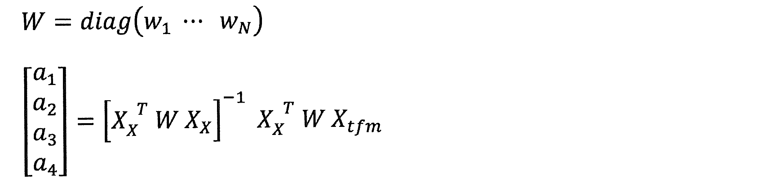
- a column vector (a 1 , a 2 , a 3 , a 4 ) T may be calculated as follows using the weighted least squares method.
- the matching unit 47 converts the position (targetx m , targety m ) of the target parking position 30 on the map coordinate system stored in the map data 46 into a position (targetx, targety) on the vehicle coordinate system using the following equation.
- the target trajectory generation unit 48 When the target trajectory generation unit 48 receives a travel trajectory calculation command from the parking support control unit 41, the target trajectory generation unit 48 moves from the current position of the own vehicle 1 on the vehicle coordinate system (that is, the coordinate origin) to the target parking position 30 (targetx, targety). A target travel trajectory and a target vehicle speed profile for the vehicle 1 traveling on the target travel trajectory are calculated.
- the steering control unit 49 receives a steering control command from the parking assistance control unit 41
- the steering control unit 49 controls the steering actuator 18a so that the own vehicle 1 travels along the target travel trajectory.
- the vehicle speed control unit 50 Upon receiving the vehicle speed control command from the parking assistance control unit 41, the vehicle speed control unit 50 controls the accelerator actuator 18b and the brake actuator 18c so that the vehicle speed of the own vehicle 1 changes according to the target vehicle speed profile. As a result, the own vehicle 1 is controlled to travel along the target travel trajectory.
- the parking support control unit 41 determines whether the vehicle 1 has reached the target parking position 30 and the parking support control has been completed. When the parking support control is completed, the parking support control unit 41 operates the parking brake 17 and switches the shift position to the parking range (hereinafter referred to as "P range").
- FIG. 5 is a flowchart of an example of processing for storing target learning positions.
- the driver operates the parking position learning switch to manually park the vehicle 1 at the target parking position.
- the image conversion unit 42 acquires a surrounding image by converting an image captured by the camera of the external sensor 14 into a bird's-eye view image viewed from a virtual viewpoint right above the own vehicle 1 .
- the feature point detection unit 44 performs predetermined preprocessing such as noise removal, brightness adjustment, and edge enhancement on the surrounding image output from the image conversion unit 42 .
- the feature point detection unit 44 detects feature points from the preprocessed surrounding image.
- step S4 the feature point detection unit 44 extracts common feature points common to two different frames.
- step S5 the map generator 45 stores the feature points extracted in step S4 in the storage device 21.
- FIG. 6 is a flowchart of an example of processing when parking assistance is performed.
- the image conversion unit 42 acquires a surrounding image.
- the feature point detection unit 44 performs predetermined preprocessing on the surrounding image output from the image conversion unit 42 . Feature points are detected from the preprocessed surrounding image in step S12.
- step S13 the feature point detection unit 44 extracts common feature points common to two different frames.
- step S14 the parking assistance control unit 41 determines whether or not the distance between the host vehicle 1 and the target parking position 30 is equal to or less than the first predetermined distance. If the distance between the host vehicle 1 and the target parking position 30 is equal to or less than the first predetermined distance (step S14: Y), the process proceeds to step S15. If the distance between the own vehicle 1 and the target parking position 30 is not equal to or less than the first predetermined distance (step S14: N), the process returns to step S10.
- step S15 the parking assistance control unit 41 determines whether or not a shift operation for steering has been detected. If a shift operation for switching is detected (step S15: Y), the process proceeds to step S16. If no shift operation for switching is detected (step S15: N), the process proceeds to step S24.
- step S16 the parking assistance control unit 41 determines whether or not the parking assistance permission condition is satisfied. If the parking assistance permission condition is satisfied (step S16: Y), the process proceeds to step S17. If the parking assistance permission condition is not satisfied (step S16: N), the process proceeds to step S23.
- step S ⁇ b>17 the matching unit 47 reads feature points stored in the map data 46 as target learning positions.
- step S18 the matching unit 47 matches the feature points extracted in step S13 with the feature points read in step S17.
- step S19 the matching unit 47 calculates the target parking position 30 based on the matched feature points.
- the target trajectory generator 48 calculates a target travel trajectory from the current position of the vehicle 1 to the target parking position 30, and a target vehicle speed profile along which the vehicle 1 travels on the target travel trajectory.
- step S21 the steering control unit 49 controls the steering actuator 18a so that the vehicle 1 travels along the target travel trajectory.
- the vehicle speed control unit 50 controls the accelerator actuator 18b and the brake actuator 18c so that the vehicle speed of the own vehicle 1 changes according to the target vehicle speed profile.
- step S22 the parking support control unit 41 determines whether or not the parking support control has been completed. When the parking support control is completed, the parking support control unit 41 operates the parking brake 17 and switches the shift position to the P range. Processing then ends.
- step S16: N if the parking assistance permission condition is not satisfied in step S16 (step S16: N), the parking assistance control unit 41 suppresses parking assistance control in step S23. Processing then ends. Further, if the shift operation for turning is not detected in step S15 (step S15: N), the parking assist control unit 41 determines in step S24 whether or not the parking assist start switch has been operated by the driver. If the parking support activation switch has been operated (step S24: Y), the process proceeds to step S17 to execute parking support control. If the parking support activation switch is not operated (step S24: N), the process returns to step S10.
- the controller 16 detects the current position of the vehicle 1, that is, the current position of the vehicle 1, calculates a target travel trajectory from the vehicle 1 to the target parking position, and determines that the distance between the vehicle 1 and the target parking position is the first. It is determined whether or not the distance is less than or equal to a predetermined distance, and a condition that a predetermined time or more has passed since the vehicle 1 started from the target parking position, or a condition that the vehicle 1 has started from the target parking position and the target parking position is determined.
- the distance between the self-position and the target parking position satisfies a parking assistance permission condition, which is either the condition that the distance between the self-position and the target parking position exceeds a second predetermined distance that is less than or equal to the first predetermined distance.
- a parking assistance permission condition which is either the condition that the distance between the self-position and the target parking position exceeds a second predetermined distance that is less than or equal to the first predetermined distance.
- Parking assistance control may be performed when the parking assistance permission condition is satisfied and the position of the shift lever is in the reverse range. This makes it possible to more appropriately prevent parking assist control that is not intended by the driver.
- the controller 16 may perform parking assist control by controlling the own vehicle 1 to travel along the target travel trajectory.
- the parking support control may be suppressed by reducing the speed of the own vehicle 1 traveling along the target travel trajectory compared to when the parking support permission conditions are satisfied.
- the driver can stop the continuation of the unintended parking support control by, for example, operating the brake at a stage when the vehicle travel distance by the parking support control is short. can.
- parking support control may be prohibited when the parking support permission conditions are not satisfied. As a result, parking assistance control that is not intended by the driver can be suppressed.
- the controller 16 may perform parking assistance control by displaying the target travel trajectory and the position of the own vehicle 1 on a display device that is visible to the occupant. If the conditions for permitting parking assistance are not met, displaying the target travel trajectory and the position of the vehicle 1 on the display device may be prohibited. As a result, parking assistance control that is not intended by the driver can be suppressed.
Landscapes
- Engineering & Computer Science (AREA)
- Automation & Control Theory (AREA)
- Transportation (AREA)
- Mechanical Engineering (AREA)
- Human Computer Interaction (AREA)
- Chemical & Material Sciences (AREA)
- Combustion & Propulsion (AREA)
- Control Of Driving Devices And Active Controlling Of Vehicle (AREA)
- Traffic Control Systems (AREA)
- Control Of Transmission Device (AREA)
- Steering Control In Accordance With Driving Conditions (AREA)
Abstract
Description
本発明は、自車両が駐車スペースに近づくと自動で駐車支援を開始する利便性と、駐車スペースから発車させた直後の運転者が意図しない駐車支援の実行防止を両立することを目的とする。
本発明の目的及び利点は、特許請求の範囲に示した要素及びその組合せを用いて具現化され達成される。前述の一般的な記述及び以下の詳細な記述の両方は、単なる例示及び説明であり、特許請求の範囲のように本発明を限定するものでないと解するべきである。
図1を参照する。自車両1は、目標駐車位置への自車両1の駐車を支援する駐車支援装置10を備える。駐車支援装置10による駐車支援では、自車両1の現在位置から目標駐車位置までの目標走行軌道を算出する。そして、自車両1が目標走行軌道に沿って走行することを支援する。駐車支援装置10による駐車支援は、自車両1が目標走行軌道に沿って走行することを支援する様々な形態を含む。例えば、自車両1の目標走行軌道に沿って目標駐車位置まで走行するように自車両1を制御する自動運転を行うことによって、自車両1の駐車を支援してもよい。なお、自車両1の目標走行軌道に沿って目標駐車位置まで走行するように自車両1を制御する自動運転とは、自車両の操舵角、駆動力、制動力の全て、あるいは一部を制御して、自車両1の目標走行軌道に沿った走行の全てあるいは一部を自動的に実施し、乗員の駐車操作を支援する制御を意味する。また、目標走行軌道と自車両1の現在位置とを自車両1の乗員が視認可能な表示装置に表示することによって、自車両1の駐車を支援してもよい。
ヒューマンマシンインタフェース12は、駐車支援装置10と乗員との間で情報を授受するインタフェース装置である。ヒューマンマシンインタフェース12は、自車両1の乗員が視認可能な表示装置(例えば、ナビゲーションシステムの表示画面)や、警報音や通知音、音声情報を出力するためのスピーカやブザーを備える。
またヒューマンマシンインタフェース12は、駐車支援装置10への乗員の操作入力を受け付ける操作子を備える。操作子は、ボタンやスイッチ、レバー、ダイヤル、キーボード等の機械的なインタフェース装置であってもよく、タッチパネル上に表示されたボタンやスイッチ、レバー、ダイヤル、キーボード等であってもよい。
外界センサ14は、自車両1から所定距離範囲(例えば外界センサ14の検出領域)の物体を検出する。外界センサ14は、自車両1の周囲に存在する物体と自車両1との相対位置、自車両1と物体との距離、物体が存在する方向などの自車両1の周囲環境を検出する。外界センサ14は、例えば自車両1の周囲環境を撮影するカメラを含んでよい。カメラは、例えば自車両1の周囲の路面を撮影して、鳥瞰図(アラウンドビューモニター画像)に変換される撮像画像を生成するアラウンドビューモニターカメラであってもよい。外界センサ14は、レーザレンジファインダ(LRF)やレーダ、LiDAR(Light Detection and Ranging)のレーザレーダなどの測距装置を含んでもよい。
以下に説明するコントローラ16の機能は、例えばプロセッサ20が、記憶装置21に格納されたコンピュータプログラムを実行することにより実現される。なお、コントローラ16を、以下に説明する各情報処理を実行するための専用のハードウエアにより形成してもよい。
ステアリングアクチュエータ18aは、コントローラ16からの制御信号に応じて操舵機構の操舵方向及び操舵量を制御する。アクセルアクチュエータ18bは、コントローラ16からの制御信号に応じて、エンジンや駆動モータである駆動装置のアクセル開度を制御する。ブレーキアクチュエータ18cは、コントローラ16からの制御信号に応じて制動装置を作動させる。
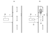
図2(a)を参照する。運転者が、駐車支援装置10による駐車支援を利用する際には、自車両1を駐車させる目標位置である目標駐車位置30付近に存在する物標の物標位置を、記憶装置21に記憶させる。
物標は、自車両1の現在位置を特定するための目印となる地物であり、自車両1の周囲の路面に描かれた路面標示(道路標識、区画線及び道路標示)や道路境界、縁石、ガードレール、電柱などの障害物であってよい。
例えば、駐車支援装置10は、外界センサ14であるカメラで撮像した撮像画像から路面標示や道路境界などの物標を表す部分の画像を特徴点として検出し、特徴点の位置を物標位置としてよい。駐車支援装置10は、検出した特徴点の特徴量も検出する。また例えば、外界センサ14であるレーザレンジファインダやレーダ、LiDARにより得られた点群情報の特徴点と、その特徴量(例えば特徴点の濃淡や属性等)を検出してもよい。本明細書では、撮像画像から特徴点を検出する例について説明する。
駐車支援装置10は、運転者が手動運転で自車両1を目標駐車位置30に駐車させる間に、外界センサ14で検出した物標位置(例えば、カメラで撮像した撮像画像から検出した特徴点とその特徴量)を記憶装置21に記憶する。以下、記憶装置21に記憶した物標位置を「物標学習位置」と表記することがある。
例えば、運転者がヒューマンマシンインタフェース12を操作することによって、自車両1の現在位置が目標駐車位置30であることを駐車支援装置10に入力してよい。駐車支援装置10は、自車両1が目標駐車位置30に位置するときに外界センサ14で検出した物標位置に基づいて、物標学習位置と目標駐車位置30との間の相対位置関係を求めてもよい。
記憶装置21に物標学習位置と目標駐車位置30との間の相対位置関係を記憶する際には、例えば、各々の物標学習位置と目標駐車位置30の位置とを、固定の地点を基準点とする座標系(以下「地図座標系」と表記する)上の座標として記憶してもよい。共通の地図座標系における物標学習位置と目標駐車位置30の座標の差分から、これらの相対位置関係を得ることができる。
物標学習位置として地図座標系上の座標を記憶する場合には、自車両1が目標駐車位置30に位置するときに測位装置11で測定した地図座標系上の現在位置を、目標駐車位置30として記憶してもよい。
また、地図座標系の代わりに、各々の物標学習位置に対する目標駐車位置30のそれぞれの相対位置を記憶してもよい。
図2(b)を参照する。駐車支援装置10は、自車両1と目標駐車位置30の距離が第1所定距離以下であるか否かを判定する。
また、駐車支援装置10は、運転者が自車両1の前進と後退を切り替える切返しのためのシフト操作を行ったか否かを判定する。図2(b)は切返し位置31で自車両が切返しを行う例を示している。なお「切返し」とは、前進から後退へ切り替える場合と、後退から前進へ切り替える場合の両者を含んでよい。駐車支援装置10は、シフトポジションがドライブレンジ(以下「Dレンジ」と表記する)からリバースレンジ(以下「Rレンジ」と表記する)に切り替わったり、RレンジからDレンジに切り替わった場合に、切返しのためのシフト操作が行われたと判定してよい。
駐車支援装置10は、自車両1と目標駐車位置30の距離が第1所定距離以下であり、且つ切返しのためのシフト操作が行われると、自動的に駐車支援を実施する。なお、第1所定距離は予め定められた任意の距離であり、設計的に適宜設定された距離である。また、駐車支援装置10は、自車両1と目標駐車位置30の距離が第1所定距離以下であり、且つ駐車支援起動スイッチが操作されると自車両1の運転支援を実施する。なお、本実施例においては自車両1と目標駐車位置30の距離が第1所定距離以下であり、且つ切返しのためのシフト操作あるいは駐車支援起動スイッチ操作がなされた場合に自車両1の運転支援を実施する例を記載しているが、運転支援を実施する条件はこれに限らない。例えば、自車両1と目標駐車位置30の距離が第1所定距離以下であり且つハザードランプが点灯された場合、あるいは自車両1と目標駐車位置30の距離が第1所定距離以下であり且つ車両が停車した場合に自車両1の運転支援を実施しても良い。すなわち、自車両1と目標駐車位置30の距離が第1所定距離以下であることを含んだ、所定の条件が成立した場合に自車両1の運転支援を実施すればよい。
このとき、外界センサ14は、外界センサ14の検出領域に存在する物標の位置である物標位置を検出する。駐車支援実施時に外界センサ14が検出した物標位置を三角形プロットで示す。なお、外界センサ14による物標位置の検出はシフト操作や駐車支援起動スイッチが操作に関係なく常に実施されていても良く、外界センサ14による物標位置の検出タイミングは限定されない。
駐車支援装置10は、外界センサ14で検出した各々の物標位置(三角形プロット)と自車両1との間の相対位置関係と、これらの物標位置(三角形プロット)に対応付けられた物標学習位置(丸プロット)と目標駐車位置30との間の相対位置関係に基づいて、自車両1の現在位置と目標駐車位置30との間の相対位置関係を算出する。
例えば、駐車支援装置10は、自車両1の現在位置を基準とする座標系(以下「車両座標系」と表記する)上の目標駐車位置30の位置を算出してもよい。例えば、地図座標系における物標学習位置(丸プロット)と目標駐車位置30の座標が記憶装置21に記憶されている場合には、駐車支援実施時に検出した車両座標系における物標位置(三角形プロット)と、地図座標系における物標学習位置(丸プロット)に基づいて、地図座標系上の目標駐車位置30を、車両座標系上の目標駐車位置30に変換してよい。
または、駐車支援実施時に検出した車両座標系における物標位置(三角形プロット)と地図座標系における物標学習位置(丸プロット)に基づいて、地図座標系上の自車両1の現在位置を求め、地図座標系における自車両1の座標と目標駐車位置30の座標の差分から、自車両1の現在位置と目標駐車位置30との間の相対位置関係を算出してもよい。
駐車支援装置10は、自車両1の現在位置と目標駐車位置30との間の相対位置関係に基づいて、自車両1の現在位置から切返し位置31を介して目標駐車位置30へ至る目標走行軌道を算出する。
また例えば、駐車支援起動スイッチの操作により駐車支援を開始した時点の自車両1の位置が目標駐車位置30の付近の位置33である場合には、位置33から切返し位置31まで進む軌道34と、切返し位置31から目標駐車位置30へ至る軌道32を目標走行軌道として算出する。
すなわち、「切返し位置を介して目標駐車位置へ至る目標走行軌道」には、切返し位置31から出発して目標駐車位置30へ至る目標走行軌道32と、位置33から切返し位置31まで進み、切返し位置31で切り返して目標駐車位置30へ至る目標走行軌道34、32の両者を含む。
そして、駐車支援装置10は、算出した目標走行軌道に基づいて自車両1の駐車支援制御を実施する。自車両1の駐車支援制御として、算出した目標走行軌道に沿って走行するように自車両1を制御(自動運転)してもよく、ヒューマンマシンインタフェース12の表示装置に目標走行軌道を表示してもよい。
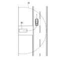
そこで駐車支援装置10は、図3に示すように自車両1が目標駐車位置30から発車したことを検出すると、自車両1が目標駐車位置30から第1所定距離以下の予め定められた所定距離である第2所定距離の範囲35を超えるまで、又は発車してから予め定められた所定時間を経過するまで、駐車支援制御を抑制する。なお、第2所定距離は第1所定距離と同様に予め定められた任意の距離であり、設計的に適宜設定された距離である。また、予め定められた所定時間も任意の時間であり、設計的に適宜設定された時間である。なお、予め定められた所定時間は、自車両1が目標駐車位置30から発車してから第2所定距離走行するまでの時間を考慮して設定される事が望ましい。
これにより、自車両が駐車スペースに近づくと自動で駐車支援を開始する利便性と、駐車スペースから発車させた直後の運転者が意図しない駐車支援の実行防止を両立できる。
HMI制御部40は、ヒューマンマシンインタフェース12の駐車位置学習スイッチが運転者に操作されると、物標学習位置を記憶装置21に記憶させる地図生成指令を地図生成部45に出力する。
またHMI制御部40は、運転者が切返しのためのシフト操作を行ったか否かを判定し、判定結果を駐車支援制御部41に出力する。また、ヒューマンマシンインタフェース12の駐車支援起動スイッチが運転者に操作されたことを検出すると、検出結果を駐車支援制御部41に出力する。
また例えば、目標駐車位置30付近の物標の特徴量を予め記憶し、類似する特徴量を有する物標を外界センサ14が検出するか否かに基づいて、自車両1と目標駐車位置30との距離が第1所定距離以下であるか否かを判定してよい。また、外界センサ14の検出範囲を自車両から第1所定距離の範囲とし、目標駐車位置30付近の物標に類似する特徴量が検出された場合に、自車両1と目標駐車位置30との距離が第1所定距離以下であることを判定しても良い。
駐車支援許可条件は、例えば、自車両1が目標駐車位置30から発車してから所定時間以上経過したという条件であってよい。これに代えて又は加えて、駐車支援許可条件は、自車両1が目標駐車位置30から発車してから自車両1の現在位置と目標駐車位置30との間の距離が、第1所定距離以下の第2所定距離を超えたという条件であってもよい。
駐車支援許可条件が満たされる場合、駐車支援制御部41は駐車支援制御を開始する。
また、自車両1と目標駐車位置30との距離が第1所定距離以下であり、且つ駐車支援起動スイッチの操作をHMI制御部40が検出すると、駐車支援制御部41は駐車支援制御を開始する。なお、本実施例においては駐車支援制御部41は、駐車支援起動スイッチの操作をHMI制御部40が検出すると駐車支援制御を開始する例を示すが、これに限らない。例えばシフト操作を検出した場合と同様に、駐車支援起動スイッチの操作が検出された場合に所定の駐車支援許可条件が満たされるか否かを判定し、駐車支援許可条件が満たされる場合、駐車支援制御部41は駐車支援制御を開始しても良い。
また、駐車支援制御部41は、シフト操作あるいは駐車支援起動スイッチの操作の一方のみの操作を検出し、駐車支援許可条件が満たされる場合に駐車支援制御を開始しても良い。
また、算出された目標駐車位置30の位置に基づいて、自車両1の現在位置から目標駐車位置30へ至る目標走行軌道と、自車両1が目標走行軌道を走行する目標車速プロファイルと、を算出させる走行軌道算出指令を目標軌道生成部48に出力する。
目標軌道生成部48は、自車両1の現在位置から目標駐車位置30へ至る目標走行軌道と目標車速プロファイルとを算出して駐車支援制御部41へ出力する。自車両1の現在位置から目標駐車位置30へ至る目標走行軌道の算出には、既に一般に知られている自動駐車装置に採用されている周知の手法を適用することができるが一例として、例えば自車両1の現在位置から切返し位置31を経て目標駐車位置30までをクロソイド曲線で接続することによって算出することができる。また、目標車速プロファイルは一例として、予め定められた所定の設定速度を基本とし、自車両1の現在位置から設定速度まで加速した後に、切返し位置31の手前で減速して切返し位置31で停車し、切返し位置31から設定速度まで加速して目標駐車位置30の手前で減速して目標駐車位置30で停車するような車速プロファイルを算出することができる。あるいはまた、速度プロファイルを算出する際の設定速度を、算出した目標走行軌道の曲率に基づいて、曲率が大きいほど低い速度となる様に設定しても良い。
HMI制御部40は、目標走行軌道と、自車両1の現在位置と、切返し位置の位置表示を、ヒューマンマシンインタフェース12の表示装置へ表示する。
また、駐車支援制御部41は、算出された目標走行軌道に沿って自車両1を走行させるように操舵制御する操舵制御指令を操舵制御部49へ出力する。また、算出された目標車速プロファイルに従って自車両1の車速を制御する車速制御指令を車速制御部50へ出力する。
または、目標走行軌道と自車両1の現在位置を表示装置に表示する運転支援を禁止してもよい。
また、駐車支援制御部41は、車速制御部50によって制御される自車両1の車速を算出された目標車速プロファイルよりも低くなるように制限することにより駐車支援制御を抑制してもよい。例えば駐車支援制御部41は、自車両1の車速を目標車速プロファイルよりも低くする車速制御指令を車速制御部50に出力してもよい。あるいは、算出した目標車速プロファイルにおける最高速度を所定の設定速度よりも低い速度に制限し、最高速度を制限した目標車速プロファイルに基づいた車速制御指令を車速制御部50に出力してもよい。すなわち、駐車支援許可条件が満たされない場合には、駐車支援許可条件が満たされた場合よりも、目標駐車位置まで走行する際の自車両1の移動速度(車速)が低減されていれば良い。
特徴点検出部44は、画像変換部42から出力される周囲画像に、ノイズ除去、明度調整及びエッジ強調などの所定の前処理を実施する。特徴点検出部44は、前処理が実施された周囲画像から特徴点とその特徴量を検出する。例えば、特徴点検出部44はFAST検出器やFREAK記述子を用いて特徴点と特徴量を検出してよい。
記憶装置21に物標学習位置を記憶する際に検出された特徴点を図2(a)の丸プロットで示している。また、駐車支援制御を実施する際に検出された特徴点を図2(b)の三角形プロットで示している。
さらに、特徴点検出部44は、異なる2フレームに共通する共通特徴点を抽出する。共通特徴点を抽出することにより、立体物や、雨滴、自車両影、移動物を検出した特徴点を除去できる。
特徴点検出部44は、共通特徴点として抽出された特徴点と、周囲画像を取得した時に自己位置算出部43から受信した自車両1の現在位置と、を同期させて地図生成部45と突合部47に出力する。
地図生成部45は、地図生成指令を受信すると、特徴点検出部44から出力された特徴点と、これに同期した自車両1の現在位置と、特徴点の特徴量と、を含んだ特徴点情報を物標学習位置として記憶装置21に記憶し、地図データ46を生成する。
特徴点に同期した自車両1の現在位置に基づいて、特徴点の地図座標系の位置を算出して特徴点情報として記憶してもよい。
また、運転者がヒューマンマシンインタフェース12を操作して、自車両1の現在位置が目標駐車位置30であることを駐車支援装置10に入力すると、地図生成部45は、自車両1の地図座標系上の現在位置を、測位装置11又は自己位置算出部43から受信して、目標駐車位置30として地図データ46に記憶する。すなわち、目標駐車位置30と複数の特徴点との相対位置関係を地図データとして記憶する。
突合部47は、駐車位置算出指令を受信すると、地図データ46に物標学習位置として記憶されている特徴点情報(図2(a)の丸プロット)と、駐車支援実施時に外界センサ14のカメラが出力する撮像画像から特徴点検出部44から出力されている特徴点情報(図2(b)の三角形プロット)とをマッチングして、同一の物標について検出した特徴点情報どうしを対応付ける。
このとき、突合部47は、互いに対応付けられた特徴点のうち、2次元アフィン変換に合致しない特徴点を外れ値として除去してよい。外れ値の検出には、例えばRANSAC(Random Sample Consensus)アルゴリズムを用いてもよい。また、互いに対応付けられた特徴点のうち、濃淡や属性などの特徴量が一致しない特徴点を除去しても良い。
例えば、駐車支援実施時に検出された特徴点を(xi,yi)と表記し、特徴点(xi,yi)にそれぞれ対応付けられた、地図データ46に物標学習位置として記憶されている特徴点を(xmi,ymi)と表記する(i=1~N)。
突合部47は、最小二乗法に基づいて次式によりアフィン変換行列Maffineを算出する。


操舵制御部49は、駐車支援制御部41から操舵制御指令を受信すると、自車両1が目標走行軌道に沿って自車両1を走行するようにステアリングアクチュエータ18aを制御する。
車速制御部50は、駐車支援制御部41から車速制御指令を受信すると、自車両1の車速が目標車速プロファイルに従って変化するように、アクセルアクチュエータ18bとブレーキアクチュエータ18cを制御する。
これにより、目標走行軌道に沿って走行するように自車両1が制御される。
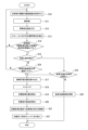
図5は、物標学習位置を記憶する処理の一例のフローチャートである。物標学習位置を記憶装置21に記憶する際に、運転者は駐車位置学習スイッチを操作して、手動運転によって自車両1を目標駐車位置に駐車する。
ステップS1において画像変換部42は、外界センサ14のカメラの撮像画像を自車両1の真上の仮想視点から見た鳥瞰画像に変換することにより周囲画像を取得する。
ステップS2において特徴点検出部44は、画像変換部42から出力される周囲画像に、ノイズ除去、明度調整及びエッジ強調などの所定の前処理を実施する。
ステップS3において特徴点検出部44は、前処理が実施された周囲画像から特徴点を検出する。
ステップS5において地図生成部45は、ステップS4で抽出された特徴点を記憶装置21に記憶する。
ステップS10において画像変換部42は、周囲画像を取得する。
ステップS11において特徴点検出部44は、画像変換部42から出力される周囲画像に所定の前処理を実施する。
ステップS12において前処理が実施された周囲画像から特徴点を検出する。
ステップS14において駐車支援制御部41は、自車両1と目標駐車位置30との距離が第1所定距離以下であるか否かを判定する。自車両1と目標駐車位置30との距離が第1所定距離以下である場合(ステップS14:Y)に処理はステップS15に進む。自車両1と目標駐車位置30との距離が第1所定距離以下でない場合(ステップS14:N)にステップS10に戻る。
ステップS16において駐車支援制御部41は、駐車支援許可条件が満たされるか否かを判定する。駐車支援許可条件が満たされる場合(ステップS16:Y)に処理はステップS17へ進む。駐車支援許可条件が満たされない場合(ステップS16:N)に処理はステップS23に進む。
ステップS18において突合部47は、ステップS13で抽出した特徴点とステップS17で読み込んだ特徴点とをマッチングする。
ステップS19において突合部47は、マッチングした特徴点に基づいて、目標駐車位置30を算出する。
ステップS20において目標軌道生成部48は、自車両1の現在位置から、目標駐車位置30まで至る目標走行軌道と、自車両1が目標走行軌道を走行する目標車速プロファイルとを算出する。
ステップS22において駐車支援制御部41は、駐車支援制御が完了したか否かを判定する。駐車支援制御が完了すると、駐車支援制御部41は、パーキングブレーキ17を作動させると共に、シフトポジションをPレンジに切り替える。その後に処理は終了する。
また、ステップS15において切返しのためのシフト操作を検出しない場合(ステップS15:N)、ステップS24において駐車支援制御部41は、駐車支援起動スイッチが運転者に操作されたか否かを判定する。駐車支援起動スイッチが操作された場合(ステップS24:Y)に処理はステップS17へ進み、駐車支援制御を実行する。駐車支援起動スイッチが操作されない場合(ステップS24:N)に処理はステップS10に戻る。
(1)コントローラ16は、自車両1の現在位置である自己位置を検出し、自己位置から目標駐車位置に至る目標走行軌道を算出し、自己位置と目標駐車位置との間の距離が第1所定距離以下であるか否かを判定し、自車両1が目標駐車位置から発車してから所定時間以上経過したという条件、又は自車両1が目標駐車位置から発車してから自己位置と目標駐車位置との間の距離が、第1所定距離以下の第2所定距離を超えたという条件、のいずれかである駐車支援許可条件を満たすか否かを判定し、自己位置と目標駐車位置との間の距離が第1所定距離以下であると判定され、且つ駐車支援許可条件を満たす場合に、目標走行軌道に基づく自車両1の駐車支援制御を実施し、自己位置と目標駐車位置との間の距離が第1所定距離以下であると判定されても、駐車支援許可条件を満たさない場合に駐車支援制御を抑制する。
これにより、自車両が駐車スペースに近づくと自動で駐車支援を開始する利便性と、駐車スペースから発車させた直後の運転者が意図しない駐車支援の実行防止とを両立できる。
Claims (8)
- 自車両の現在位置である自己位置を検出し、
前記自己位置から目標駐車位置に至る目標走行軌道を算出し、
前記自己位置と前記目標駐車位置との間の距離が第1所定距離以下であるか否かを判定し、
前記自車両が前記目標駐車位置から発車してから所定時間以上経過したという条件、又は前記自車両が前記目標駐車位置から発車してから前記自己位置と前記目標駐車位置との間の距離が、前記第1所定距離以下の第2所定距離を超えたという条件、のいずれかである駐車支援許可条件を満たすか否かを判定し、
前記自己位置と目標駐車位置との間の距離が第1所定距離以下であると判定され、且つ前記駐車支援許可条件を満たす場合に、前記目標走行軌道に基づく前記自車両の駐車支援制御を実施し、
前記自己位置と目標駐車位置との間の距離が第1所定距離以下であると判定されても、前記駐車支援許可条件を満たさない場合に前記駐車支援制御を抑制する、
ことを特徴とする駐車支援方法。 - 前記自己位置と目標駐車位置との間の距離が第1所定距離以下であると判定され、且つ前記駐車支援許可条件を満たす場合であって、シフトレバーの位置がリバースレンジである場合に、前記駐車支援制御を実施することを特徴とする請求項1に記載の駐車支援方法。
- 前記駐車支援制御は、前記目標走行軌道に沿って走行するように前記自車両を制御することを特徴とする請求項1又は2に記載の駐車支援方法。
- 前記駐車支援許可条件を満たさない場合には、前記駐車支援許可条件を満たす場合よりも前記目標走行軌道に沿って走行させる前記自車両の速度を低減することにより、前記駐車支援制御を抑制することを特徴とする請求項3に記載の駐車支援方法。
- 前記駐車支援許可条件を満たさない場合には、前記駐車支援制御を禁止することを特徴とする請求項3に記載の駐車支援方法。
- 前記駐車支援制御は、前記目標走行軌道及び前記自車両の位置を、乗員が視認可能な表示装置に表示することを特徴とする請求項1又は2に記載の駐車支援方法。
- 前記駐車支援許可条件を満たさない場合には、前記目標走行軌道及び前記自車両の位置を前記表示装置に表示することを禁止する請求項6に記載の駐車支援方法。
- 自車両の現在位置である自己位置を検出するためのセンサ又は測位装置と、
前記自己位置から目標駐車位置に至る目標走行軌道を算出し、前記自己位置と前記目標駐車位置との間の距離が第1所定距離以下であるか否かを判定し、前記自車両が前記目標駐車位置から発車してから所定時間以上経過したという条件、又は前記自車両が前記目標駐車位置から発車してから前記自己位置と前記目標駐車位置との間の距離が、前記第1所定距離以下の第2所定距離を超えたという条件、のいずれかである駐車支援許可条件を満たすか否かを判定し、前記自己位置と目標駐車位置との間の距離が第1所定距離以下であると判定され、且つ前記駐車支援許可条件を満たす場合に、前記目標走行軌道に基づく前記自車両の駐車支援制御を実施し、前記自己位置と目標駐車位置との間の距離が第1所定距離以下であると判定されても、前記駐車支援許可条件を満たさない場合に前記駐車支援制御を抑制するコントローラと、
を備えることを特徴とする駐車支援装置。
Priority Applications (6)
| Application Number | Priority Date | Filing Date | Title |
|---|---|---|---|
| JP2023538205A JP7491476B2 (ja) | 2021-07-30 | 2021-07-30 | 駐車支援方法及び駐車支援装置 |
| PCT/JP2021/028509 WO2023007749A1 (ja) | 2021-07-30 | 2021-07-30 | 駐車支援方法及び駐車支援装置 |
| EP21951134.2A EP4378777A4 (en) | 2021-07-30 | 2021-07-30 | PARKING ASSISTANCE METHOD AND PARKING ASSISTANCE DEVICE |
| CN202180100739.8A CN117677553B (zh) | 2021-07-30 | 2021-07-30 | 驻车辅助方法以及驻车辅助装置 |
| MX2024001345A MX2024001345A (es) | 2021-07-30 | 2021-07-30 | Metodo de asistencia al estacionamiento y dispositivo de asistencia al estacionamiento. |
| US18/578,758 US12214777B2 (en) | 2021-07-30 | 2021-07-30 | Parking assist method and parking assist device |
Applications Claiming Priority (1)
| Application Number | Priority Date | Filing Date | Title |
|---|---|---|---|
| PCT/JP2021/028509 WO2023007749A1 (ja) | 2021-07-30 | 2021-07-30 | 駐車支援方法及び駐車支援装置 |
Publications (1)
| Publication Number | Publication Date |
|---|---|
| WO2023007749A1 true WO2023007749A1 (ja) | 2023-02-02 |
Family
ID=85086521
Family Applications (1)
| Application Number | Title | Priority Date | Filing Date |
|---|---|---|---|
| PCT/JP2021/028509 Ceased WO2023007749A1 (ja) | 2021-07-30 | 2021-07-30 | 駐車支援方法及び駐車支援装置 |
Country Status (6)
| Country | Link |
|---|---|
| US (1) | US12214777B2 (ja) |
| EP (1) | EP4378777A4 (ja) |
| JP (1) | JP7491476B2 (ja) |
| CN (1) | CN117677553B (ja) |
| MX (1) | MX2024001345A (ja) |
| WO (1) | WO2023007749A1 (ja) |
Cited By (1)
| Publication number | Priority date | Publication date | Assignee | Title |
|---|---|---|---|---|
| WO2026042256A1 (ja) * | 2024-08-23 | 2026-02-26 | 日産自動車株式会社 | 駐停車制御方法、駐停車制御装置及び駐停車制御システム |
Families Citing this family (1)
| Publication number | Priority date | Publication date | Assignee | Title |
|---|---|---|---|---|
| JP7743726B2 (ja) * | 2021-08-02 | 2025-09-25 | 日産自動車株式会社 | 駐車支援方法及び駐車支援装置 |
Citations (3)
| Publication number | Priority date | Publication date | Assignee | Title |
|---|---|---|---|---|
| JP2001106115A (ja) * | 1999-10-04 | 2001-04-17 | Yazaki Corp | 駐車支援システムにおける指示装置及びその指示プログラムを記録したコンピュータ読み取り可能な記録媒体 |
| JP2004330891A (ja) * | 2003-05-08 | 2004-11-25 | Fujitsu Ten Ltd | 利便性向上装置 |
| WO2017072941A1 (ja) | 2015-10-30 | 2017-05-04 | 三菱電機株式会社 | 駐車支援装置および駐車支援方法 |
Family Cites Families (6)
| Publication number | Priority date | Publication date | Assignee | Title |
|---|---|---|---|---|
| JP5182545B2 (ja) * | 2007-05-16 | 2013-04-17 | アイシン精機株式会社 | 駐車支援装置 |
| JP5212748B2 (ja) * | 2010-09-29 | 2013-06-19 | アイシン精機株式会社 | 駐車支援装置 |
| WO2014091613A1 (ja) | 2012-12-13 | 2014-06-19 | トヨタ自動車株式会社 | 駐車支援装置 |
| JP7120036B2 (ja) | 2019-01-16 | 2022-08-17 | トヨタ自動車株式会社 | 自動駐車管理装置 |
| JP2021095113A (ja) | 2019-06-24 | 2021-06-24 | 本田技研工業株式会社 | 駐車支援システム |
| JP7247850B2 (ja) | 2019-10-11 | 2023-03-29 | トヨタ自動車株式会社 | 駐車支援装置 |
-
2021
- 2021-07-30 MX MX2024001345A patent/MX2024001345A/es unknown
- 2021-07-30 WO PCT/JP2021/028509 patent/WO2023007749A1/ja not_active Ceased
- 2021-07-30 JP JP2023538205A patent/JP7491476B2/ja active Active
- 2021-07-30 CN CN202180100739.8A patent/CN117677553B/zh active Active
- 2021-07-30 US US18/578,758 patent/US12214777B2/en active Active
- 2021-07-30 EP EP21951134.2A patent/EP4378777A4/en not_active Withdrawn
Patent Citations (3)
| Publication number | Priority date | Publication date | Assignee | Title |
|---|---|---|---|---|
| JP2001106115A (ja) * | 1999-10-04 | 2001-04-17 | Yazaki Corp | 駐車支援システムにおける指示装置及びその指示プログラムを記録したコンピュータ読み取り可能な記録媒体 |
| JP2004330891A (ja) * | 2003-05-08 | 2004-11-25 | Fujitsu Ten Ltd | 利便性向上装置 |
| WO2017072941A1 (ja) | 2015-10-30 | 2017-05-04 | 三菱電機株式会社 | 駐車支援装置および駐車支援方法 |
Non-Patent Citations (1)
| Title |
|---|
| See also references of EP4378777A4 |
Cited By (1)
| Publication number | Priority date | Publication date | Assignee | Title |
|---|---|---|---|---|
| WO2026042256A1 (ja) * | 2024-08-23 | 2026-02-26 | 日産自動車株式会社 | 駐停車制御方法、駐停車制御装置及び駐停車制御システム |
Also Published As
| Publication number | Publication date |
|---|---|
| CN117677553A (zh) | 2024-03-08 |
| US20240367642A1 (en) | 2024-11-07 |
| JPWO2023007749A1 (ja) | 2023-02-02 |
| EP4378777A1 (en) | 2024-06-05 |
| EP4378777A4 (en) | 2024-10-09 |
| CN117677553B (zh) | 2024-12-06 |
| MX2024001345A (es) | 2024-02-15 |
| US12214777B2 (en) | 2025-02-04 |
| JP7491476B2 (ja) | 2024-05-28 |
Similar Documents
| Publication | Publication Date | Title |
|---|---|---|
| JP7448403B2 (ja) | 駐車枠認識システム、及び、駐車枠認識システムを備えた駐車支援システム | |
| JP7816484B2 (ja) | 駐車支援方法及び駐車支援装置 | |
| JP7491476B2 (ja) | 駐車支援方法及び駐車支援装置 | |
| WO2023100230A1 (ja) | 駐車支援方法及び駐車支援装置 | |
| JP2007309670A (ja) | 車両位置検出装置 | |
| JP7743726B2 (ja) | 駐車支援方法及び駐車支援装置 | |
| WO2024157443A1 (ja) | 駐車支援方法及び運転支援装置 | |
| JP7771820B2 (ja) | 駐車支援方法及び駐車支援装置 | |
| JP7715204B2 (ja) | 駐車支援方法及び駐車支援装置 | |
| JP7761147B2 (ja) | 駐車支援方法及び駐車支援装置 | |
| WO2024157441A1 (ja) | 駐車支援方法及び駐車支援装置 | |
| JP7608960B2 (ja) | 駐車支援方法及び駐車支援装置 | |
| WO2024157442A1 (ja) | 駐車支援方法及び駐車支援装置 | |
| JP7616419B2 (ja) | 駐車支援方法及び駐車支援装置 | |
| WO2023119656A1 (ja) | 駐車支援方法及び駐車支援装置 | |
| WO2024157449A1 (ja) | 駐車支援方法及び駐車支援装置 | |
| WO2024184974A1 (ja) | 駐車支援方法及び駐車支援装置 | |
| WO2024013807A1 (ja) | 駐車支援方法及び駐車支援装置 | |
| WO2024157444A1 (ja) | 駐車支援方法及び駐車支援装置 | |
| WO2025088729A1 (ja) | 駐車支援方法及び駐車支援装置 | |
| WO2025257900A1 (ja) | 駐車支援方法及び駐車支援装置 | |
| WO2025088730A1 (ja) | 駐車支援方法及び駐車支援装置 | |
| WO2024157461A1 (ja) | 駐車支援方法及び駐車支援装置 | |
| WO2024157460A1 (ja) | 駐車支援方法及び駐車支援装置 | |
| WO2026028346A1 (ja) | 駐車支援方法、駐車支援装置及び駐車支援システム |
Legal Events
| Date | Code | Title | Description |
|---|---|---|---|
| 121 | Ep: the epo has been informed by wipo that ep was designated in this application |
Ref document number: 21951134 Country of ref document: EP Kind code of ref document: A1 |
|
| WWE | Wipo information: entry into national phase |
Ref document number: 2023538205 Country of ref document: JP |
|
| WWE | Wipo information: entry into national phase |
Ref document number: 202180100739.8 Country of ref document: CN |
|
| WWE | Wipo information: entry into national phase |
Ref document number: MX/A/2024/001345 Country of ref document: MX |
|
| REG | Reference to national code |
Ref country code: BR Ref legal event code: B01A Ref document number: 112024001676 Country of ref document: BR |
|
| WWE | Wipo information: entry into national phase |
Ref document number: 202447012840 Country of ref document: IN |
|
| WWE | Wipo information: entry into national phase |
Ref document number: 2021951134 Country of ref document: EP |
|
| NENP | Non-entry into the national phase |
Ref country code: DE |
|
| ENP | Entry into the national phase |
Ref document number: 2021951134 Country of ref document: EP Effective date: 20240229 |
|
| ENP | Entry into the national phase |
Ref document number: 112024001676 Country of ref document: BR Kind code of ref document: A2 Effective date: 20240126 |
|
| WWW | Wipo information: withdrawn in national office |
Ref document number: 2021951134 Country of ref document: EP |