WO2023017601A1 - 電気化学セル、電気化学セルを使用した発電方法、及び電気化学セルを使用した水素ガスの製造方法 - Google Patents
電気化学セル、電気化学セルを使用した発電方法、及び電気化学セルを使用した水素ガスの製造方法 Download PDFInfo
- Publication number
- WO2023017601A1 WO2023017601A1 PCT/JP2021/029742 JP2021029742W WO2023017601A1 WO 2023017601 A1 WO2023017601 A1 WO 2023017601A1 JP 2021029742 W JP2021029742 W JP 2021029742W WO 2023017601 A1 WO2023017601 A1 WO 2023017601A1
- Authority
- WO
- WIPO (PCT)
- Prior art keywords
- electrochemical cell
- cathode
- hydrogen
- anode
- proton conductor
- Prior art date
- Legal status (The legal status is an assumption and is not a legal conclusion. Google has not performed a legal analysis and makes no representation as to the accuracy of the status listed.)
- Ceased
Links
Images


Classifications
-
- H—ELECTRICITY
- H01—ELECTRIC ELEMENTS
- H01M—PROCESSES OR MEANS, e.g. BATTERIES, FOR THE DIRECT CONVERSION OF CHEMICAL ENERGY INTO ELECTRICAL ENERGY
- H01M8/00—Fuel cells; Manufacture thereof
- H01M8/10—Fuel cells with solid electrolytes
- H01M8/12—Fuel cells with solid electrolytes operating at high temperature, e.g. with stabilised ZrO2 electrolyte
- H01M8/124—Fuel cells with solid electrolytes operating at high temperature, e.g. with stabilised ZrO2 electrolyte characterised by the process of manufacturing or by the material of the electrolyte
- H01M8/1246—Fuel cells with solid electrolytes operating at high temperature, e.g. with stabilised ZrO2 electrolyte characterised by the process of manufacturing or by the material of the electrolyte the electrolyte consisting of oxides
-
- C—CHEMISTRY; METALLURGY
- C25—ELECTROLYTIC OR ELECTROPHORETIC PROCESSES; APPARATUS THEREFOR
- C25B—ELECTROLYTIC OR ELECTROPHORETIC PROCESSES FOR THE PRODUCTION OF COMPOUNDS OR NON-METALS; APPARATUS THEREFOR
- C25B1/00—Electrolytic production of inorganic compounds or non-metals
- C25B1/01—Products
- C25B1/02—Hydrogen or oxygen
- C25B1/04—Hydrogen or oxygen by electrolysis of water
- C25B1/042—Hydrogen or oxygen by electrolysis of water by electrolysis of steam
-
- C—CHEMISTRY; METALLURGY
- C25—ELECTROLYTIC OR ELECTROPHORETIC PROCESSES; APPARATUS THEREFOR
- C25B—ELECTROLYTIC OR ELECTROPHORETIC PROCESSES FOR THE PRODUCTION OF COMPOUNDS OR NON-METALS; APPARATUS THEREFOR
- C25B13/00—Diaphragms; Spacing elements
- C25B13/04—Diaphragms; Spacing elements characterised by the material
- C25B13/05—Diaphragms; Spacing elements characterised by the material based on inorganic materials
- C25B13/07—Diaphragms; Spacing elements characterised by the material based on inorganic materials based on ceramics
-
- C—CHEMISTRY; METALLURGY
- C25—ELECTROLYTIC OR ELECTROPHORETIC PROCESSES; APPARATUS THEREFOR
- C25B—ELECTROLYTIC OR ELECTROPHORETIC PROCESSES FOR THE PRODUCTION OF COMPOUNDS OR NON-METALS; APPARATUS THEREFOR
- C25B15/00—Operating or servicing cells
- C25B15/08—Supplying or removing reactants or electrolytes; Regeneration of electrolytes
-
- C—CHEMISTRY; METALLURGY
- C25—ELECTROLYTIC OR ELECTROPHORETIC PROCESSES; APPARATUS THEREFOR
- C25B—ELECTROLYTIC OR ELECTROPHORETIC PROCESSES FOR THE PRODUCTION OF COMPOUNDS OR NON-METALS; APPARATUS THEREFOR
- C25B9/00—Cells or assemblies of cells; Constructional parts of cells; Assemblies of constructional parts, e.g. electrode-diaphragm assemblies; Process-related cell features
- C25B9/05—Pressure cells
-
- C—CHEMISTRY; METALLURGY
- C25—ELECTROLYTIC OR ELECTROPHORETIC PROCESSES; APPARATUS THEREFOR
- C25B—ELECTROLYTIC OR ELECTROPHORETIC PROCESSES FOR THE PRODUCTION OF COMPOUNDS OR NON-METALS; APPARATUS THEREFOR
- C25B9/00—Cells or assemblies of cells; Constructional parts of cells; Assemblies of constructional parts, e.g. electrode-diaphragm assemblies; Process-related cell features
- C25B9/17—Cells comprising dimensionally-stable non-movable electrodes; Assemblies of constructional parts thereof
- C25B9/19—Cells comprising dimensionally-stable non-movable electrodes; Assemblies of constructional parts thereof with diaphragms
-
- C—CHEMISTRY; METALLURGY
- C25—ELECTROLYTIC OR ELECTROPHORETIC PROCESSES; APPARATUS THEREFOR
- C25B—ELECTROLYTIC OR ELECTROPHORETIC PROCESSES FOR THE PRODUCTION OF COMPOUNDS OR NON-METALS; APPARATUS THEREFOR
- C25B9/00—Cells or assemblies of cells; Constructional parts of cells; Assemblies of constructional parts, e.g. electrode-diaphragm assemblies; Process-related cell features
- C25B9/60—Constructional parts of cells
- C25B9/65—Means for supplying current; Electrode connections; Electric inter-cell connections
-
- C—CHEMISTRY; METALLURGY
- C25—ELECTROLYTIC OR ELECTROPHORETIC PROCESSES; APPARATUS THEREFOR
- C25B—ELECTROLYTIC OR ELECTROPHORETIC PROCESSES FOR THE PRODUCTION OF COMPOUNDS OR NON-METALS; APPARATUS THEREFOR
- C25B9/00—Cells or assemblies of cells; Constructional parts of cells; Assemblies of constructional parts, e.g. electrode-diaphragm assemblies; Process-related cell features
- C25B9/70—Assemblies comprising two or more cells
- C25B9/73—Assemblies comprising two or more cells of the filter-press type
- C25B9/75—Assemblies comprising two or more cells of the filter-press type having bipolar electrodes
-
- C—CHEMISTRY; METALLURGY
- C25—ELECTROLYTIC OR ELECTROPHORETIC PROCESSES; APPARATUS THEREFOR
- C25B—ELECTROLYTIC OR ELECTROPHORETIC PROCESSES FOR THE PRODUCTION OF COMPOUNDS OR NON-METALS; APPARATUS THEREFOR
- C25B9/00—Cells or assemblies of cells; Constructional parts of cells; Assemblies of constructional parts, e.g. electrode-diaphragm assemblies; Process-related cell features
- C25B9/70—Assemblies comprising two or more cells
- C25B9/73—Assemblies comprising two or more cells of the filter-press type
- C25B9/77—Assemblies comprising two or more cells of the filter-press type having diaphragms
-
- H—ELECTRICITY
- H01—ELECTRIC ELEMENTS
- H01M—PROCESSES OR MEANS, e.g. BATTERIES, FOR THE DIRECT CONVERSION OF CHEMICAL ENERGY INTO ELECTRICAL ENERGY
- H01M12/00—Hybrid cells; Manufacture thereof
- H01M12/08—Hybrid cells; Manufacture thereof composed of a half-cell of a fuel-cell type and a half-cell of the secondary-cell type
-
- H—ELECTRICITY
- H01—ELECTRIC ELEMENTS
- H01M—PROCESSES OR MEANS, e.g. BATTERIES, FOR THE DIRECT CONVERSION OF CHEMICAL ENERGY INTO ELECTRICAL ENERGY
- H01M4/00—Electrodes
- H01M4/86—Inert electrodes with catalytic activity, e.g. for fuel cells
- H01M4/90—Selection of catalytic material
- H01M4/92—Metals of platinum group
- H01M4/925—Metals of platinum group supported on carriers, e.g. powder carriers
-
- H—ELECTRICITY
- H01—ELECTRIC ELEMENTS
- H01M—PROCESSES OR MEANS, e.g. BATTERIES, FOR THE DIRECT CONVERSION OF CHEMICAL ENERGY INTO ELECTRICAL ENERGY
- H01M8/00—Fuel cells; Manufacture thereof
- H01M8/06—Combination of fuel cells with means for production of reactants or for treatment of residues
- H01M8/0606—Combination of fuel cells with means for production of reactants or for treatment of residues with means for production of gaseous reactants
- H01M8/0612—Combination of fuel cells with means for production of reactants or for treatment of residues with means for production of gaseous reactants from carbon-containing material
- H01M8/0637—Direct internal reforming at the anode of the fuel cell
-
- H—ELECTRICITY
- H01—ELECTRIC ELEMENTS
- H01M—PROCESSES OR MEANS, e.g. BATTERIES, FOR THE DIRECT CONVERSION OF CHEMICAL ENERGY INTO ELECTRICAL ENERGY
- H01M8/00—Fuel cells; Manufacture thereof
- H01M8/06—Combination of fuel cells with means for production of reactants or for treatment of residues
- H01M8/0606—Combination of fuel cells with means for production of reactants or for treatment of residues with means for production of gaseous reactants
- H01M8/0656—Combination of fuel cells with means for production of reactants or for treatment of residues with means for production of gaseous reactants by electrochemical means
-
- H—ELECTRICITY
- H01—ELECTRIC ELEMENTS
- H01M—PROCESSES OR MEANS, e.g. BATTERIES, FOR THE DIRECT CONVERSION OF CHEMICAL ENERGY INTO ELECTRICAL ENERGY
- H01M8/00—Fuel cells; Manufacture thereof
- H01M8/10—Fuel cells with solid electrolytes
- H01M8/1009—Fuel cells with solid electrolytes with one of the reactants being liquid, solid or liquid-charged
-
- H—ELECTRICITY
- H01—ELECTRIC ELEMENTS
- H01M—PROCESSES OR MEANS, e.g. BATTERIES, FOR THE DIRECT CONVERSION OF CHEMICAL ENERGY INTO ELECTRICAL ENERGY
- H01M8/00—Fuel cells; Manufacture thereof
- H01M8/10—Fuel cells with solid electrolytes
- H01M8/12—Fuel cells with solid electrolytes operating at high temperature, e.g. with stabilised ZrO2 electrolyte
- H01M8/1213—Fuel cells with solid electrolytes operating at high temperature, e.g. with stabilised ZrO2 electrolyte characterised by the electrode/electrolyte combination or the supporting material
-
- H—ELECTRICITY
- H01—ELECTRIC ELEMENTS
- H01M—PROCESSES OR MEANS, e.g. BATTERIES, FOR THE DIRECT CONVERSION OF CHEMICAL ENERGY INTO ELECTRICAL ENERGY
- H01M8/00—Fuel cells; Manufacture thereof
- H01M8/10—Fuel cells with solid electrolytes
- H01M8/12—Fuel cells with solid electrolytes operating at high temperature, e.g. with stabilised ZrO2 electrolyte
- H01M8/1231—Fuel cells with solid electrolytes operating at high temperature, e.g. with stabilised ZrO2 electrolyte with both reactants being gaseous or vaporised
-
- H—ELECTRICITY
- H01—ELECTRIC ELEMENTS
- H01M—PROCESSES OR MEANS, e.g. BATTERIES, FOR THE DIRECT CONVERSION OF CHEMICAL ENERGY INTO ELECTRICAL ENERGY
- H01M8/00—Fuel cells; Manufacture thereof
- H01M8/22—Fuel cells in which the fuel is based on materials comprising carbon or oxygen or hydrogen and other elements; Fuel cells in which the fuel is based on materials comprising only elements other than carbon, oxygen or hydrogen
- H01M8/222—Fuel cells in which the fuel is based on compounds containing nitrogen, e.g. hydrazine, ammonia
-
- H—ELECTRICITY
- H01—ELECTRIC ELEMENTS
- H01M—PROCESSES OR MEANS, e.g. BATTERIES, FOR THE DIRECT CONVERSION OF CHEMICAL ENERGY INTO ELECTRICAL ENERGY
- H01M8/00—Fuel cells; Manufacture thereof
- H01M8/10—Fuel cells with solid electrolytes
- H01M8/12—Fuel cells with solid electrolytes operating at high temperature, e.g. with stabilised ZrO2 electrolyte
- H01M2008/1293—Fuel cells with solid oxide electrolytes
-
- H—ELECTRICITY
- H01—ELECTRIC ELEMENTS
- H01M—PROCESSES OR MEANS, e.g. BATTERIES, FOR THE DIRECT CONVERSION OF CHEMICAL ENERGY INTO ELECTRICAL ENERGY
- H01M2300/00—Electrolytes
- H01M2300/0017—Non-aqueous electrolytes
- H01M2300/0065—Solid electrolytes
- H01M2300/0068—Solid electrolytes inorganic
- H01M2300/0071—Oxides
- H01M2300/0074—Ion conductive at high temperature
-
- Y—GENERAL TAGGING OF NEW TECHNOLOGICAL DEVELOPMENTS; GENERAL TAGGING OF CROSS-SECTIONAL TECHNOLOGIES SPANNING OVER SEVERAL SECTIONS OF THE IPC; TECHNICAL SUBJECTS COVERED BY FORMER USPC CROSS-REFERENCE ART COLLECTIONS [XRACs] AND DIGESTS
- Y02—TECHNOLOGIES OR APPLICATIONS FOR MITIGATION OR ADAPTATION AGAINST CLIMATE CHANGE
- Y02E—REDUCTION OF GREENHOUSE GAS [GHG] EMISSIONS, RELATED TO ENERGY GENERATION, TRANSMISSION OR DISTRIBUTION
- Y02E60/00—Enabling technologies; Technologies with a potential or indirect contribution to GHG emissions mitigation
- Y02E60/30—Hydrogen technology
- Y02E60/50—Fuel cells
Definitions
- the present invention relates to an electrochemical cell, a method of generating electricity using the electrochemical cell, and a method of producing hydrogen gas using the electrochemical cell.
- PEFC Polymer electrolyte fuel cells
- PAFC phosphoric acid fuel cells
- MCFC molten carbonate fuel cells
- SOFC solid oxide fuels Batteries
- the operating temperature is room temperature to 100°C for polymer electrolyte fuel cells, 180 to 200°C for phosphoric acid fuel cells, 600 to 700°C for molten carbonate fuel cells, and 600 to 900°C for solid oxide fuel cells. is. However, there is no fuel cell that operates in the medium temperature range of 200-600°C.
- Fuel cells that operate in the medium temperature range of 200 to 600°C are not only hydrogen-oxygen fuel cells, but also generate hydrogen from various fuels in the fuel electrode chamber of the fuel cell, and use the generated hydrogen by the fuel cell reaction. Suitable for direct fuel cells that generate power.
- a fuel cell that operates in a medium temperature range of 200 to 600° C. can promote the fuel cell reaction compared to a fuel cell that operates in a low temperature range of 200° C. or less, so efficiency can be improved.
- Patent Document 1 discloses a direct fuel cell.
- an organic hydride compound such as methylcyclohexane and decalin is supplied as a fuel to a fuel cell, and is brought into contact with a noble metal catalyst fixed to the electrode of the fuel electrode for dehydrogenation.
- Non-Patent Document 1 indicates that the demonstration of the entire system of a large-scale hydrogen supply chain by the organic chemical hydride method using a dehydrogenation catalyst has been completed internationally and is moving to the commercialization stage.
- This dehydrogenation catalyst has a high yield and a long service life that can be used at the industrial level, and is originally intended to be used for the purpose of generating hydrogen by a dehydrogenation reaction at the place of use from hydrogen stored in methylcyclohexane.
- the dehydrogenation reaction is an endothermic reaction, a heat source is required, and the cost of the heat source is high. There is a problem that lowers the assessment CO 2 ).
- Patent Document 1 hydrogen generated at the fuel electrode transfers electrons to the fuel electrode and becomes protons. Protons move in the electrolyte membrane and receive electrons from the electrode together with oxygen atoms activated at the air electrode of the counter electrode to advance the fuel cell reaction.
- the electrolyte membrane is a membrane made of a mixture of microcrystals of cesium dihydrogen phosphate (CsH 2 SO 4 ) and polytetrafluoroethylene.
- the direct fuel cell of Patent Document 1 has an output of 40 mW/cm 2 at an operating temperature of 170-220°C.
- the operating temperature is generally 100°C or less, and the heat resistance of the organic film is not sufficient at 200°C or more.
- Cesium dihydrogen phosphate is known as a solid electrolyte that can be used at 200° C. or higher.
- the use limit temperature of cesium dihydrogen phosphate is 270° C., there is a demand for a novel proton conductor that can be used at even higher temperatures.
- Non-Patent Document 2 discloses Li 13.9 Sr 0.1 Zn ( Li 13.9 Sr 0.1 Zn ( GeO 4 ) 4 are disclosed. Li 13.9 Sr 0.1 Zn(GeO 4 ) 4 exhibits a conductivity of 0.039 S/cm at 600° C., which is higher than that of conventional zirconia-based or ceria-based solid electrolytes. A fuel cell using Li13.9Sr0.1Zn ( GeO4 ) 4 has an output of about 0.4 W/ cm2 at an operating temperature of 600C.
- Li 13.9 Sr 0.1 Zn(GeO 4 ) 4 improves the conductivity to 0.048 S/cm at an operating temperature of 600°C.
- Lithium ions and protons are exchanged in water or dilute acetic acid.
- ion exchange has been performed by stirring Li 13.9 Sr 0.1 Zn(GeO 4 ) 4 in 5 mM aqueous acetic acid for 24 hours.
- Non-Patent Document 3 discloses a proton conductor in which Li 14-2x Zn 1+x (GeO 4 ) 4 is ion-exchanged in a 5 mM acetic acid aqueous solution to exchange lithium ions for protons.
- ion exchange is performed on Li 14 Zn(GeO 4 ) 4 , Li 12 Zn 2 (GeO 4 ) 4 and Li 10 Zn 3 (GeO 4 ) 4 with varying Li + /Zn 2+ ratios.
- identifying each sample and measuring the weight change during heating it was confirmed that the amount of ion-exchanged to protons is greater in samples with a higher lithium content.
- Non-Patent Document 3 finds the possibility of obtaining the same conductivity as the proton conductor disclosed in Non-Patent Document 2 from the results of electromotive force measurement of a hydrogen concentration cell using a proton conductor. .
- the operating temperature can be set at 200 to 600° C., and the dehydrogenation reaction of the organic hydride compound can be promoted at the fuel electrode.
- the operating temperature can be set to 200 to 600° C., and the efficiency of the electrolytic reaction can be improved.
- the present invention provides an electrochemical cell suitable for use in a temperature range of 200 to 600 ° C., a power generation method using the electrochemical cell, and a method for producing hydrogen gas using the electrochemical cell.
- the task is to
- an aspect of the present invention is an electrochemical cell (1), wherein some of the lithium ions of Li 14-2x Zn 1+x (GeO 4 ) 4 where x is a number of 0 or more are a proton conductor (5) which is proton-substituted (Li, H) 14-2x Zn 1+x (GeO 4 ) 4 and has a conductivity of 0.01 S/cm or more at 300° C.; an anode (6) provided on one side, a cathode (7) provided on the other side of said proton conductor, and a second anode (6) provided on said anode side of said proton conductor and forming an anode chamber (8).
- the structure in which some of the lithium ions of Li 14-2x Zn 1+x (GeO 4 ) 4 are substituted with protons is (Li, H) 14-2x Zn 1+x (GeO 4 ) 4 or (Li, H) 2+2y It can be written as Zn 1-y GeO 4 .
- an electrochemical cell suitable for use in the temperature range of 200 to 600°C can be provided. Electrochemical cells can be used as fuel cells and electrolysers.
- the above aspect may have temperature control means for maintaining the temperature of the proton conductor at 200°C or higher and 600°C or lower.
- the electrical conductivity of the proton conductor can be maintained at a high level.
- the x may be 0.
- Mobile lithium ions refer to lithium ions that can move in Li 14-2x Zn 1+x (GeO 4 ) 4 among all lithium ions contained in Li 14-2x Zn 1+x (GeO 4 ) 4 .
- the ratio of mobile lithium ions to all lithium ions in Li 14-2x Zn 1+x (GeO 4 ) 4 is (3 ⁇ x)/(14 ⁇ 2x).
- the electrical conductivity of the proton conductor can be improved.
- the first separator of one of the cells is: It may be in heat exchange contact with the second separator of another one of the cells.
- the heat generated by the reaction between protons and oxygen at the cathode is transferred to the anode through the first separator and the second separator. This facilitates maintaining the temperature of the proton conductor at 200.degree. C. to 600.degree.
- hydrogen is supplied to the anode chamber, air is supplied to the cathode chamber, an electromotive force is generated between the anode and the cathode, and the electrochemical cell functions as a hydrogen-oxygen fuel cell. good.
- a hydrogen-oxygen fuel cell can be provided.
- a hydrogen-containing compound containing hydrogen is supplied to the anode chamber, air is supplied to the cathode chamber, and a catalyst layer containing a catalyst for generating hydrogen gas from the hydrogen-containing compound is provided in the anode chamber.
- an electromotive force may be generated between the anode and the cathode such that the electrochemical cell functions as a hydrogen-oxygen fuel cell.
- a direct fuel cell can be provided.
- the hydrogen-containing compound may be an organic hydride compound obtained by hydrogenating a 1- to 3-ring aromatic.
- the hydrogen-containing compound may contain at least one selected from the group consisting of methylcyclohexane, cyclohexane, trimethylcyclohexane, decalin, benzyltoluene, and dibenzotriol.
- the fuel supplied to the anode is an organic hydride compound.
- the reaction heat required for the endothermic reaction of generating hydrogen from the fuel can be compensated by the heat generated by the fuel cell reaction, which is an exothermic reaction in which water is generated.
- the hydrogen generated by the dehydrogenation reaction by the dehydrogenation catalyst transfers electrons to the anode in the anode chamber, becomes protons, conducts inside the proton conductor, and reaches the counter electrode, the cathode.
- a fuel cell reaction occurs that produces water and oxygen ions that have received electrons at the cathode. This causes electrons to flow through the circuit, generating electricity.
- the dehydrogenation reaction is an equilibrium reaction regulated by chemical equilibrium. For example, in the case of the dehydrogenation reaction of methylcyclohexane, almost 100% of the dehydrogenation reaction proceeds at normal reaction pressure in a normal reactor. The reaction temperature required for this is 320°C.
- the proton conductor removes protons to the counter electrode side, which has the effect of shifting the chemical equilibrium to the low temperature side.
- the dehydrogenation reaction can proceed almost 100% even at 320° C. or lower, and the dehydrogenation reaction can be promoted by increasing the operating temperature.
- the hydrogen-containing compound may contain at least one selected from the group consisting of ammonia, formic acid, methanol, and dimethyl ether.
- the catalyst may be a dehydrogenation catalyst containing an alumina carrier and platinum supported on the alumina carrier, and the average particle size of the platinum may be 2 nm or less.
- the dehydrogenation reaction of methylcyclohexane at the anode can be promoted.
- Hydrogen generated by the dehydrogenation reaction in the anode chamber transfers electrons to the anode electrode, becomes protons, and passes through the proton conductor.
- the hydrogen generated from the dehydrogenation reaction field is removed, so that the chemical equilibrium shifts to the low temperature side and the dehydrogenation reaction is promoted.
- a platinum-supported alumina catalyst developed by Chiyoda Corporation can be used.
- This catalyst is a catalyst in which platinum particles are highly dispersed on the surface of porous ⁇ -alumina used as a catalyst carrier.
- Platinum-supported alumina catalysts have long been used in many reactions, but the platinum particles of conventional platinum-supported alumina catalysts have a large size, and even the smallest platinum particles are 2 nm or more. 2 nm or more.
- the life of the catalyst is only a few days due to the rapid decrease of the active sites of the platinum particles.
- Most of the catalysts developed by Chiyoda Corporation have a platinum particle size of about 1 nm, an average particle size of 2 nm or less, and the platinum particles are highly dispersed on the surface of the alumina support. Therefore, the catalyst developed by Chiyoda Corporation can be used industrially for more than one year continuously by suppressing carbon deposition.
- the catalyst developed by Chiyoda Corporation was developed as a dehydrogenation catalyst for organic hydride ahead of the rest of the world, and can be used as a dehydrogenation catalyst for the dehydrogenation reaction of the organic hydride of the present invention.
- the electrochemical cell may function as an electrolytic cell such that water vapor is supplied to the anode chamber, a DC power supply is connected between the anode and the cathode, and hydrogen is produced at the cathode. . At this time, it is not necessary to supply the raw material to the cathode chamber.
- Another aspect of the present invention is a power generation method using the above electrochemical cell, wherein hydrogen is supplied to the anode chamber, air is supplied to the cathode chamber, and the temperature of the proton conductor is raised to 200° C. or higher. Maintain below 600°C.
- an electrochemical cell can be used to generate electricity using hydrogen as fuel.
- Another aspect of the present invention is a power generation method using the above electrochemical cell, wherein a catalyst layer for generating hydrogen gas from a hydrogen-containing compound is provided in the anode chamber, and the hydrogen-containing compound is generated in the anode chamber. Air is supplied to the cathode chamber, and the temperature of the proton conductor is maintained at 200° C. or higher and 600° C. or lower.
- an electrochemical cell can be used to generate electricity using a hydrogen-containing compound as fuel.
- the hydrogen-containing compound may be an organic hydride compound obtained by hydrogenating a 1- to 3-ring aromatic.
- the hydrogen-containing compound may contain at least one selected from the group consisting of methylcyclohexane, cyclohexane, trimethylcyclohexane, decalin, benzyltoluene, and dibenzotriol.
- the hydrogen-containing compound may contain at least one selected from the group consisting of ammonia, formic acid, methanol, and dimethyl ether.
- the catalyst layer may have a dehydrogenation catalyst containing an alumina carrier and platinum supported on the alumina carrier, and the average particle size of the platinum may be 2 nm or less.
- the dehydrogenation reaction of methylcyclohexane at the anode can be promoted.
- Another aspect of the present invention is a method for producing hydrogen gas by electrolysis using the above electrochemical cell, wherein water vapor is supplied to the anode chamber, water is supplied to the cathode chamber, and the proton conductor is maintained at 200° C. or higher and 600° C. or lower, and a DC voltage is applied between the anode and the cathode to generate hydrogen gas at the cathode. At this time, it is not necessary to supply the raw material to the cathode chamber.
- Another aspect of the present invention is a method for producing hydrogen gas by electrolysis using an electrochemical cell, wherein the anode chamber is provided with a catalyst, and the anode chamber contains methylcyclohexane, formic acid, methanol, and dimethyl ether.
- At least one hydrocarbon selected from the group or ammonia is supplied, the temperature of the proton conductor is maintained at 200° C. or higher and 600° C. or lower, a DC voltage is applied between the anode and the cathode, and the anode chamber protons generated from the hydrocarbon or the ammonia by the catalyst in step 1 are transferred to the cathode via the proton conductor to generate hydrogen gas at the cathode. At this time, it is not necessary to supply the raw material to the cathode chamber.
- hydrogen can be produced using the electrochemical cell.
- Another aspect of the present invention is a method for producing hydrogen gas by electrolysis using the above electrochemical cell, wherein the anode chamber is provided with a catalyst, and the anode chamber contains methylcyclohexane, formic acid, methanol, and dimethyl ether. At least one hydrocarbon selected from the group or ammonia is supplied, the temperature of the proton conductor is maintained at 200° C. or higher and 600° C. or lower, a DC voltage is applied between the anode and the cathode, and the anode chamber protons generated from the hydrocarbon or the ammonia by the catalyst in step 1 are transferred to the cathode via the proton conductor to generate hydrogen gas at the cathode.
- hydrogen can be produced using the electrochemical cell.
- Another aspect of the present invention is a method for producing hydrogen gas by electrolysis using the electrochemical cell described above, wherein the electrolysis is performed under pressurized conditions.
- high-pressure hydrogen gas can be produced.
- an electrochemical cell suitable for use in a temperature range of 200 to 600° C. a power generation method using the electrochemical cell, and a method for producing hydrogen gas using the electrochemical cell. can.
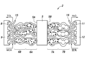
- each power generation cell 2 includes a proton conductor 5, an anode 6 provided on one side of the proton conductor 5, and a cathode 7 provided on the other side of the proton conductor 5.
- a first separator 9 provided on the anode 6 side of the proton conductor 5 and forming an anode chamber 8, and a second separator 12 provided on the cathode 7 side of the proton conductor 5 and forming a cathode chamber 11. have.
- a hydrogen-containing compound containing hydrogen is supplied to the anode chamber 8 and air is supplied to the cathode chamber 11 .
- the hydrogen-containing compound is preferably an organic hydride compound obtained by hydrogenating a 1- to 3-ring aromatic.
- the hydrogen-containing compound preferably contains at least one selected from the group consisting of methylcyclohexane, cyclohexane, trimethylcyclohexane, decalin, benzyltoluene, and dibenzotriol.
- the hydrogen-containing compound may contain at least one selected from the group consisting of ammonia, formic acid, methanol, and dimethyl ether.
- the fuel hydrogen-containing compound is methylcyclohexane (MCH).
- the anode 6 may be referred to as a fuel electrode, the cathode 7 as an air electrode, the anode chamber 8 as a fuel channel, and the cathode chamber 11 as an air channel.
- the proton conductor 5 is formed in a film shape.
- the proton conductor 5 has a structure in which part of Li in Li 14-2x Zn 1+x (GeO 4 ) 4 is replaced with protons.
- x is a number greater than or equal to 0 and may include decimals.
- Li 14-2x Zn 1+x (GeO 4 ) 4 is (Li, H) 14-2x Zn 1+x (GeO 4 ) 4 or (Li, H) 2+2y It can be written as Zn 1-y GeO 4 .
- Li 14-2x Zn 1+x (GeO 4 ) 4 is a kind of LISICON (Lithium super ionic conductor) which is a solid electrolyte. x may be 0, 1, 2, for example.
- LISICON has a framework structure formed by tetrahedrons of ⁇ -Li 3 PO 4 -type LiO 4 , GeO 4 , SiO 4 , PO 4 , ZnO 4 and VO 4 and octahedra of LiO 6 .
- Li 14 Zn(GeO 4 ) 4 is a solid solution of Zn in the matrix structure of Li 4 GeO 4 and has high conductivity.
- the proton conductor 5 has a conductivity of 0.01 S/cm or more at 300°C.
- 40% or more and 70% or less of mobile lithium ions contained in Li 14-2x Zn 1+x (GeO 4 ) 4 are replaced with protons.
- 50% or more and 60% or less of the movable lithium ions contained in Li 14-2x Zn 1+x (GeO 4 ) 4 are preferably replaced with protons.
- 40% or more and 70% or less of mobile lithium ions contained in Li 14 Zn(GeO 4 ) 4 are preferably replaced with protons.
- it is preferable that 50% or more and 60% or less of the movable lithium ions contained in Li14Zn ( GeO4 ) 4 are replaced with protons.
- Li 14-2x Zn 1+x (GeO 4 ) 4 before ion exchange is described.
- a method for preparing Li 14-2x Zn 1+x (GeO 4 ) 4 is also disclosed in Non-Patent Document 3 above.
- Li 14-2x Zn 1+x (GeO 4 ) 4 can be prepared by solid phase methods. Li source, Zn source, and Ge source reagent powders are mixed overnight in an organic solvent, and after pulverization, the organic solvent is evaporated to obtain a mixture.
- the Li source may include at least one selected from the group including LiOH, Li2O , and LiNO3 .
- the Zn source may include at least one selected from the group including Zn(OH) 2 , ZnCO 3 and Zn(NO 3 ) 2 .
- the Ge source may comprise at least one selected from the group comprising GeO and GeCl2 .
- a combination of Li source, Zn source, and Ge source may be, for example, Li 2 CO 3 , ZnO, GeO 2 .
- the organic solvent may be at least one selected from the group including ethanol, methanol, 1-propanol, 2-propanol, and 1-butanol.
- the air firing temperature of the molding is preferably 1000 to 1200°C, more preferably 1100 to 1150°C. If the firing temperature is lower than 1000°C, the solid phase reaction does not progress, and if the firing temperature is higher than 1200°C, the molding melts.
- the firing time of the molding is preferably 3 to 7 hours, more preferably 4 to 6 hours.
- the molding may be sintered, for example, at 1150° C. in air for 5 hours.
- Li 14-2x Zn 1+x (GeO 4 ) 4 may be, for example, Li 14 Zn(GeO 4 ) 4 , Li 12 Zn 2 (GeO 4 ) 4 , Li 10 Zn 3 (GeO 4 ) 4 .
- the ratio of Li to Zn in Li 14-2x Zn 1+x (GeO 4 ) 4 can be changed by changing the ratio of Li source, Zn source and Ge source to be mixed.
- Non-aqueous solvents are preferably aprotic solvents.
- the non-aqueous solvent may include one selected from the group including toluene, dimethylsulfoxide, tetrahydrofuran, N,N-dimethylformamide.
- the acid preferably contains at least one selected from the group including benzoic acid, m-nitrophenol, acetic acid, p-toluenesulfonic acid, oxalic acid, and methanesulfonic acid.
- benzoic acid Li 14-2x Zn 1+x (GeO 4 ) in 100 mL of a non-aqueous organic solution in which toluene from which water has been removed with a dehydrating agent is used as a non-aqueous solvent, and benzoic acid is dissolved to a concentration of 5 mM as a proton source. 4 is preferably stirred for 24 hours for ion exchange.
- the ion exchange rate of mobile lithium ions contained in Li 14-2x Zn 1+x (GeO 4 ) 4 to protons was adjusted by changing the concentration of Li 14-2x Zn 1+x (GeO 4 ) 4 with respect to the solvent and the acid species. can do. It has been confirmed that when the solvent is aqueous and the acid species is acetic acid, the ion exchange rate of mobile lithium ions contained in Li 14-2x Zn 1+x (GeO 4 ) 4 to protons is 100%.
- the proton conductor powder after ion exchange is obtained by removing the solvent.
- the drying temperature at this time is preferably at least the boiling point of the solvent used and at most 300°C. If the temperature is lower than the boiling point, the problem of residual solvent occurs, and if the temperature is higher than 300° C., the problem of desorption of protons in the sample occurs.
- a powdery proton conductor is thus obtained.
- a powdery proton conductor can be molded into a film by, for example, a molding machine. Also, the powdery proton conductor may be molded using a wet method or a dry method such as vapor deposition.
- the anode 6 consists of an anode catalyst layer 6A laminated on the first surface 5A of the proton conductor 5 and an anode gas diffusion layer laminated on the opposite side of the anode catalyst layer 6A from the proton conductor 5.
- the cathode 7 includes a cathode catalyst layer 7A laminated on the second surface 5B opposite to the first surface 5A of the proton conductor 5, and a cathode gas diffusion layer laminated on the side of the cathode catalyst layer 7A opposite to the proton conductor 5. 7B.
- the anode catalyst layer 6A and the cathode catalyst layer 7A each have a conductive porous support and an electrode catalyst supported by the support.
- the support is for example an ionomer.
- Electrocatalysts used in known PEFCs can be used, such as noble metal catalysts such as platinum, palladium, iridium and ruthenium.
- the electrode catalyst may be an inexpensive metal catalyst.
- the anode gas diffusion layer 6B and the cathode gas diffusion layer 7B are formed of a porous body, and reactant gases diffuse inside.
- the anode gas diffusion layer 6B and the cathode gas diffusion layer 7B are preferably made of, for example, a metal porous material or carbon fiber nonwoven fabric.
- the anode gas diffusion layer 6B and the cathode gas diffusion layer 7B are conductive.
- a dehydrogenation catalyst is bonded to at least one of the anode gas diffusion layer 6B and the anode catalyst layer 6A.
- the dehydrogenation catalyst is preferably a platinum-supported alumina catalyst used for the organic chemical hydride method.
- a platinum-supported alumina catalyst has an alumina support and platinum as an active metal supported on the alumina support. Platinum is formed in the form of particles and dispersedly supported on an alumina carrier.
- a platinum-supported alumina catalyst has activity for the dehydrogenation reaction of hydrogenated aromatics such as methylcyclohexane.
- the average particle size of the platinum particles is 2 nm or less, more preferably 0.5 nm or more and 2.0 nm or less, and still more preferably 0.8 nm or more and 1.5 nm or less. Also, 70% or more of the platinum particles should have a size of 2 nm or less, more preferably 0.5 nm or more and 2.0 nm or less, and still more preferably 0.8 nm or more and 1.5 nm or less.
- the average particle size and size of platinum may be measured by transmission electron microscopy.
- the platinum particles are preferably supported on the alumina carrier in a range of 0.1% by weight or more and 1.5% by weight or less as platinum element (Pt).
- the alumina carrier has a surface area of 200 m 2 /g or more, a pore volume of 0.50 m 2 /g or more, an average pore diameter in the range of 60 ⁇ to 150 ⁇ , and pores with an average pore diameter of ⁇ 30 ⁇ with respect to the total pore volume
- a ⁇ -alumina carrier in which the ratio of is 60% or more is preferably included.
- a platinum-supported alumina catalyst as a dehydrogenation catalyst preferably has a second component together with platinum particles.
- the second component may be at least one selected from the group consisting of alkali metals such as sodium and potassium, vanadium, molybdenum, chromium, sulfur and phosphorus.
- the second component is preferably carried on the alumina carrier in a range of 0.5 wt % to 1.5 wt %.
- the alumina carrier preferably contains sulfur or a sulfur compound in the range of 0.5% by weight or more and 1.2% by weight or less as elemental sulfur (S).
- the alumina support preferably supports an alkali metal in a range of 0.5% by weight or more and 1.5% by weight or less.
- the second component improves the selectivity of the platinum-on-alumina catalyst, thereby extending the catalyst life.
- the dehydrogenation catalyst may be provided in the anode gas diffusion layer 6B in various known forms.
- the dehydrogenation catalyst may be formed in the form of powder, and the dehydrogenation catalyst powder may be fixed to the structure forming the gas diffusion layer.
- the gas diffusion layer may be formed by pulverizing the dehydrogenation catalyst and molding the pulverized dehydrogenation catalyst.
- a dehydrogenation catalyst may be provided in the anode catalyst layer 6A.
- the first separator 9 forms an anode chamber 8 between itself and the anode gas diffusion layer 6B.
- a plurality of grooves forming the anode chamber 8 may be provided on the anode gas diffusion layer 6B side of the first separator 9 .
- a spacer 15 may be provided between the first separator 9 and the anode gas diffusion layer 6B to expand the anode chamber 8. As shown in FIG. In other embodiments, the spacer 15 may be omitted and the first separator 9 and the anode gas diffusion layer 6B may be in direct contact.
- the second separator 12 forms a cathode chamber 11 between itself and the cathode gas diffusion layer 7B.
- a plurality of grooves forming the cathode chamber 11 may be provided on the cathode gas diffusion layer 7B side of the second separator 12 .
- a spacer 16 may be provided between the second separator 12 and the cathode gas diffusion layer 7B to expand the cathode chamber 11. As shown in FIG. In other embodiments, spacer 16 may be omitted and second separator 12 and cathode gas diffusion layer 7B may be in direct contact.
- the first separator 9 and the second separator 12 are made of a heat conductor. Moreover, in this embodiment, the first separator 9 and the second separator 12 are made of an electrical conductor. The first separator 9 and the second separator 12 are preferably made of metal such as stainless steel, carbon, or a carbon resin composite. The first separator 9 is electrically connected with the anode 6 and the second separator 12 is electrically connected with the cathode 7 .
- the inlet of the anode chamber 8 of each power generation cell 2 is connected to a common fuel inlet 21.
- the outlet of the anode chamber 8 of each power generation cell 2 is connected to a common fuel outlet 22 .
- the inlet of the cathode chamber 11 of each power generation cell 2 is connected to a common air inlet 23 .
- An outlet of the cathode chamber 11 of each power generation cell 2 is connected to a common air outlet 24 .
- Each power generation cell 2 is stacked on top of each other.
- One first separator 9 of the plurality of power generation cells 2 is in contact with another one of the second separators 12 of the plurality of power generation cells 2 so as to be able to exchange heat.
- the first separator 9 and the second separator 12 of adjacent battery cells may be integrally formed.
- Adjacent power generation cells 2 are electrically connected in series by contact between the first separator 9 and the second separator 12 .
- a first separator 9 arranged at one end of the plurality of stacked power generating cells 2 is connected to the negative electrode 25 of the fuel cell stack 3 .
- a second separator 12 arranged at the other end of the plurality of stacked power generation cells 2 is connected to the positive electrode 26 of the fuel cell stack 3 .
- An external load is connected to the negative electrode 25 and the positive electrode 26 .
- the fuel inlet 21 is connected to the fuel tank 31 via the heater 32 .
- the heater 32 heats and vaporizes the liquid methylcyclohexane supplied from the fuel tank 31 .
- the heater 32 may be an electric heater having a power line that generates heat by electricity, or a heater using combustion heat of fossil fuel as a heat source. Methylcyclohexane vaporized by the heater 32 is supplied to the fuel inlet 21 .
- the fuel outlet 22 is connected to a spent fuel tank 35 via a cooler 33 and a gas-liquid separator 34.
- Cooler 33 cools the exhaust gas discharged from fuel outlet 22 .
- the exhaust gas mainly contains toluene and hydrogen produced from methylcyclohexane and unreacted methylcyclohexane.
- Cooler 33 liquefies toluene and methylcyclohexane in the exhaust gas.
- Cooler 33 cools the exhaust gas to 110.6° C. or lower, which is the boiling point of toluene.
- Cooler 33 and heater 32 may include heat exchangers that exchange heat between the fuel and the exhaust gas.
- the cooler 33 may include an air-cooled heat exchanger or a water-cooled heat exchanger.
- the gas-liquid separator 34 separates liquid toluene and methylcyclohexane from the exhaust gas.
- the separated toluene and methylcyclohexane are stored in the spent fuel tank 35 .
- the gaseous component of the exhaust gas from which liquid toluene and methylcyclohexane have been separated is mainly hydrogen.
- a gaseous component of the exhaust gas is preferably sent from the gas-liquid separator 34 to the fuel inlet 21 of the fuel cell stack 3 via a pipe.
- the inlet of the cathode chamber 11 is connected to an intake pipe that takes in air.
- An outlet of the cathode chamber 11 is connected to a discharge pipe for discharging air and water to the outside.
- the fuel cell 1 may have temperature control means for maintaining the temperature of the proton conductor 5 between 200°C and 600°C.
- the temperature control means may maintain the temperature of the proton conductor 5 between 250°C and 600°C.
- the temperature control means may be a heater 32 that controls the temperature of methylcyclohexane supplied to the anode chamber 8 .
- the temperature control means may be a temperature control device 41 including an air cooling device that cools the fuel cell stack 3 with outside air or a water cooling device that cools the fuel cell stack 3 with cooling water.
- the temperature control means may be a flow control valve that controls the flow rate of methylcyclohexane supplied to the anode chamber 8 .
- the power generation method using the fuel cell 1 has a step of maintaining the temperature of the proton conductor at 200°C or higher and 600°C or lower.
- the temperature of the fuel cell 1 is preferably maintained at 200° C. or higher and 600° C. or lower by a temperature control means.
- Methylcyclohexane is supplied from a fuel tank 31 to the anode chamber 8 of each power generation cell 2 of the fuel cell 1 through a fuel inlet 21 .
- Methylcyclohexane is heated in the heater 32 and supplied to the anode chamber 8 after being vaporized.
- Air containing oxygen as an oxidant is supplied to the cathode chamber 11 of each power generating cell 2 of the fuel cell 1 through an air inlet 23 .
- Methylcyclohexane supplied to the anode chamber 8 diffuses into the anode gas diffusion layer 6B.
- methylcyclohexane is decomposed into hydrogen and toluene by the dehydrogenation reaction represented by the following reaction formula (1). This reaction is endothermic.
- the temperature of the anode chamber 8 is maintained at 200 to 600° C. by utilizing reaction heat of the cathode reaction (reaction formula (3)) described later.
- the hydrogen produced by the dehydrogenation reaction releases electrons and produces protons in the anode catalyst layer 6A in the presence of the electrode catalyst through the anode reaction represented by the following reaction formula (2).
- Protons generated in the anode catalyst layer 6A pass through the inside of the proton conductor 5 and reach the cathode catalyst layer 7A.
- protons and oxygen receive electrons and produce water by the cathode reaction represented by the following reaction formula (3).
- Cathodic reactions are exothermic reactions. An electromotive force is thereby generated between the anode 6 and the cathode 7 .
- the heat generated in the cathode catalyst layer 7A is transmitted to the anode catalyst layer 6A and the anode gas diffusion layer 6B through the proton conductor 5, and the cathode gas diffusion layer 7B, the second separator 12, and the first separator 9. through the anode catalyst layer 6A and the anode gas diffusion layer 6B.
- the anode catalyst layer 6A and the anode gas diffusion layer 6B are maintained at 200 to 600° C., promoting the dehydrogenation reaction.
- FIG. 3 is a graph showing the conductivity of various solid electrolytes.
- the conductivity plotted with circles indicates the conductivity of the proton conductor ((Li, H) 14 Zn(GeO 4 ) 4 ) according to this embodiment.
- the electrical conductivity of the proton conductor according to this embodiment at 300°C is higher than that of cesium dihydrogen phosphate (CsH 2 PO 4 ) at 250°C.
- the electrical conductivity of the proton conductor according to the present embodiment at 600° C. is higher than that of various solid electrolytes used in SOFCs.
- Nafion ion-exchange membrane which is a type of organic polymer ion-exchange membrane used in automotive fuel cells
- the conductivity of the proton conductor 5 according to this embodiment at 500 to 600°C is equivalent to the conductivity of the Nafion membrane at an operating temperature of about 90°C.
- a PEFC using a Nafion ion exchange membrane is a 100 kW class fuel cell and is small in size. SOFCs are much larger in size than PEFCs.
- the proton conductor 5 according to this embodiment is used as a solid electrolyte, the operating temperature of the current SOFC can be lowered and the size can be reduced.
- the proton conductor 5 according to this embodiment has a conductivity higher than that of cesium dihydrogen phosphate as a solid electrolyte that operates in the temperature range of 200°C to 250°C.
- the proton conductor 5 according to this embodiment has high conductivity even in the temperature range of 300 to 600.degree.
- the proton conductor 5 according to this embodiment has a conductivity equivalent to that of the Nafion ion-exchange membrane used in automotive fuel cells in a temperature range of 500° C. or higher.
- the proton conductor 5 according to the present embodiment can be used at a high temperature of 600° C. or higher, and the conductivity at 600° C. is equivalent to that of the solid electrolyte used in existing SOFCs at operating temperatures of 600° C.
- the proton conductor 5 according to the present embodiment moves protons instead of oxide ions, it has high electrical conductivity, and its operating temperature can be lowered to about 600.degree. As a result, the proton conductor 5 according to this embodiment can provide a fuel cell that is more efficient and easier to handle than the existing SOFC.
- Li 14-2x Zn 1+x (GeO 4 ) 4 is immersed and stirred in a non-aqueous organic solution containing an acid to form Li 14-2x Zn 1+x (GeO 4 )
- the ion exchange rate of mobile lithium ions contained in 4 to protons can be 40% or more and 70% or less.
- the proton conductor has improved structural stability and relatively high electrical conductivity.
- Li 14-2x Zn 1+x (GeO 4 ) 4 is immersed in an acetic acid aqueous solution and stirred, ion exchange of mobile lithium ions contained in Li 14-2x Zn 1+x (GeO 4 ) 4 to protons occurs. It has been confirmed that the rate is 100%. However, it has been confirmed that the proton conductor in this case has low structural stability, and a by-product phase is generated when the powder is molded, resulting in a decrease in electrical conductivity. When a non-aqueous solvent is used in the production of the proton conductor, the ion exchange rate is lower than when an aqueous solvent is used, but the electrical conductivity is increased due to improved structural stability.
- the fuel cell 1 uses the proton conductor 5, which has a relatively high electrical conductivity at 200-600°C, so it can generate power efficiently. Moreover, since heat generated by the cathode reaction at the cathode 7 is used for the dehydrogenation reaction, energy efficiency can be improved.
- the inventors of the present application have found that protons can be moved by exchanging lithium ions for hydrogen ions (protons) in lysicon, and that high conductivity can be obtained by ion exchange in a non-aqueous solution rather than an aqueous solution. and completed the fuel cell 1 (electrochemical cell) according to the embodiment.
- the proton conductor 5 of the fuel cell 1 according to the embodiment can improve electrical conductivity compared to conventional proton conductors.
- the proton conductor 5 of the fuel cell 1 according to the embodiment has an electrical conductivity ⁇ of CsH 2 PO 4 , which has been attracting attention as a material exhibiting the highest electrical conductivity, at an operating temperature of 250°C.
- the proton conductor 5 of the fuel cell 1 it is possible to configure a medium-temperature electrochemical cell that operates at 200 ° C. to 600 ° C., which has not been put into practical use so far. It can be used for various purposes such as tanks.
- the fuel cell 1 (electrochemical cell) according to the present embodiment can be expected to improve the cell performance nearly 10 times compared to the conventional fuel cell using CsH 2 PO 4 operating at 200 to 600°C. Electrode materials containing noble metals used in conventional solid oxide fuel cells and electrolytic cells can be used even in the temperature range of 200 to 600° C., and the higher the temperature, the faster the reaction rate.
- a decomposition catalyst that generates hydrogen from the fuel is essential depending on the type of fuel, and these decomposition catalysts can use existing industrial thermochemical catalysts, and the reaction rate is Big enough.
- the performance of the electrochemical cell to which CsH 2 PO 4 is applied is rate-determined by the rate of proton conduction, and that the performance is proportional to the electrical conductivity of the proton conductor. It is very likely that about 10 times the cell performance can be achieved by applying
- the fuel may contain at least one selected from the group consisting of ammonia, formic acid, methanol, and dimethyl ether instead of methylcyclohexane.
- ammonia is used as the fuel, it is preferable to replace the dehydrogenation catalyst in the fuel cell according to the first embodiment with a known ammonia decomposition catalyst.
- the ammonia decomposition catalyst is a catalyst that promotes a decomposition reaction that produces hydrogen and nitrogen from ammonia, and may be, for example, a ruthenium-based catalyst, a cobalt-based catalyst, or a nickel-based catalyst.
- the formic acid reforming catalyst is a catalyst that promotes a reforming reaction that produces hydrogen and carbon dioxide from formic acid, and is preferably an iridium complex catalyst, for example.
- methanol is used as the fuel, it is preferable to replace the dehydrogenation catalyst in the fuel cell according to the first embodiment with a known methanol reforming catalyst.
- the methanol reforming catalyst is a catalyst that promotes a reforming reaction that produces hydrogen and carbon dioxide from methanol and water, and is preferably an iridium complex catalyst, for example.
- dimethyl ether When dimethyl ether is used as the fuel, it is preferable to replace the dehydrogenation catalyst in the fuel cell according to the first embodiment with a known dimethyl ether reforming catalyst. Since any reaction that produces hydrogen from ammonia, formic acid, methanol, or dimethyl ether is an endothermic reaction, the heat generated by the cathode reaction can be used to promote the reaction.
- hydrogen gas may be supplied to the anode chamber 8 as fuel.
- the dehydrogenation catalyst may be omitted from the anode chamber 8 .
- Each power generation cell 2 of the fuel cell according to the first embodiment can also be used as an electrolytic cell 50 as shown in FIG.
- the proton conductor 5 functions as an ion exchange membrane
- the first separator 9 and the second separator 12 function as the container 52 .
- the anode 55 is connected to the positive pole of the DC power supply 53 and the cathode 56 is connected to the negative pole of the DC power supply 53 .
- a DC voltage is thereby applied between the anode 55 and the cathode 56 .
- Anode 55 and cathode 56 are electrically insulated from container 54 .
- Anode chamber 58 and cathode chamber 59 are separated from each other by proton conductor 5 .
- the anode chamber 58 may be supplied with a first substance to be oxidized and the cathode chamber 59 may be supplied with a second substance to be reduced.
- the electrolytic bath 50 may be used for electrolysis in a temperature range of 200°C or higher and 600°C or lower. Electrolyzer 50 may be used, for example, for high-temperature steam electrolysis. Water vapor may be supplied to the anode chamber 58 as the first substance, and nothing may be supplied to the cathode chamber 59. Steam or a purge gas such as nitrogen may be supplied as the second substance. In this electrolytic cell 50, water molecules transfer electrons to the anode 55 to generate oxygen and protons (2H 2 O ⁇ O 2 +4H + +4e ⁇ ).
- Protons generated at the anode 55 pass through the proton conductor 5 and move to the cathode 56, where they receive electrons and become hydrogen molecules (2H + +2e ⁇ ⁇ H 2 ). Oxygen gas is thereby generated in the anode chamber 58 and hydrogen gas is generated in the cathode chamber 59 .
- the electrolytic bath 50 may be used for electrolysis of hydrocarbons or ammonia in a temperature range of 200°C or higher and 600°C or lower. Electrolyser 50 may be used, for example, to produce hydrogen from hydrocarbons.
- the anode 55 is provided with a reforming catalyst instead of the dehydrogenation catalyst.
- Hydrocarbon gas and steam as the first substance are preferably supplied to the anode chamber 58 .
- the hydrocarbon may include at least one selected from the group including methylcyclohexane, formic acid, methanol, dimethyl ether. Hydrocarbons may also include lower hydrocarbons such as methane, ethane, propane, butane, and the like.
- the hydrocarbon and water transfer electrons to the anode 55 at the anode 55 to produce protons and carbon monoxide.
- the protons pass through the proton conductor 5 and move to the cathode 56, where they receive electrons and become hydrogen molecules.
- carbon monoxide is produced in the anode chamber 58 and hydrogen molecules are produced in the cathode chamber 59, so that synthesis gas can be produced by electrolysis of hydrocarbon gas. Since only hydrogen is produced in the cathode chamber 59, high-purity hydrogen can be produced.
- Electrolysis may also be performed under pressurized conditions. In this case, the pressure of the gas supplied to the anode chamber 58 and the cathode chamber 59 of the electrolytic cell 50 should be increased.
- the electrolytic cell 50 may be used for electrolytic reduction of carbon dioxide in a temperature range of 200°C or higher and 600°C or lower. Electrolyser 50 may be used, for example, for the electrolytic production of synthesis gas, such as ethylene, from carbon dioxide.
- the anode 55 is provided with a carbon dioxide reduction catalyst instead of the dehydrogenation catalyst.
- the carbon dioxide reduction catalyst contains at least one of, for example, a group 11 element such as copper, a group 12 element such as zinc, a group 13 element such as gallium, a group 14 element such as germanium, or a metal compound thereof. .
- the anode chamber 58 may be supplied with water as the first substance, and the cathode chamber 59 may be supplied with carbon dioxide as the second substance.
- carbon dioxide is reduced at the cathode 56 to produce ethylene and water (2CO 2 +12H + +12e ⁇ ⁇ C 2 H 4 +4H 2 O).
- water is oxidized to produce oxygen (2H 2 O ⁇ O 2 +4H + +4e ⁇ ). This produces oxygen in the anode chamber 58 and ethylene in the cathode chamber 59 .
- the electrolytic cell 50 uses the proton conductor 5 having high conductivity in the medium temperature range of 200 to 600° C. as an ion exchange membrane, electrolysis with an equivalent current density at a temperature lower than 600° C. becomes possible.
- the electrolytic cell 50 according to this embodiment can also be applied to a method of electrochemically producing light hydrocarbons such as ethylene and formic acid from carbon dioxide and hydrogen. Conventionally, in this method, since a polymer membrane is used as an ion exchange membrane, there is a problem that the reaction rate is slow. Since the electrolytic cell 50 according to this embodiment operates at 200 to 600° C., the current density can be increased. Thereby, a compact electrolytic cell can be realized.
- the electrolytic cell 50 according to the present embodiment can also be applied to a method of selectively separating hydrogen in a hydrogen gas-containing gas and compressing to increase the pressure. Since the electrolytic cell 50 according to this embodiment operates at 200 to 600° C., hydrogen purification and compression can be efficiently performed.
- Lithium carbonate was used as the Li source, zinc oxide as the Zn source, and germanium oxide as the Ge source. Lithium carbonate, zinc oxide, and germanium oxide were added in a weight ratio of 25:4:21, and the slurry was finely mixed with ethanol and zirconia balls for 24 hours in a closed vessel. , and molded into pellets in a press. The pellets were calcined in air at 1150° C. for 5 hours in an alumina crucible, pulverized in a magnetic mortar for 2 hours, formed into pellets again, and calcined in air at 1150° C. for 5 hours in an alumina crucible. The fired pellets were again pulverized in a magnet mortar for 2 hours to obtain Li 14 Zn(GeO 4 ) 4 powder before ion exchange.
- Example 1 A 2.5 g sample of Li 14 Zn(GeO 4 ) 4 powder before ion exchange was mixed with toluene from which water was removed with a dehydrating agent as a non-aqueous solvent, and benzoic acid was added as a proton source to a concentration of 5 mM. Ion exchange was carried out in 100 ml of dissolved non-aqueous organic solution with stirring for 24 hours. After the ion exchange, the powder was collected by filtration, washed with toluene, and vacuum-dried at 130° C. overnight to obtain the ion-exchanged powder of Example 1. The ion exchange rate of mobile lithium ions to protons in the proton conductor of Example 1 was 52%.
- Example 1 Comparison between Example 1 and Comparative Example 1
- the conductivity of the ion exchangers of Example 1 and Comparative Example 1 was measured.
- the measurement was performed using an electrochemical evaluation device (ModuLab, manufactured by Solartron Analytical) in a 10% humidified nitrogen atmosphere by a direct current four-terminal method and an alternating current two-terminal method.
- the measurement results are shown in Table 1 below.
- Example 1 had a higher electrical conductivity than Comparative Example 1.
- Example 2 Using dimethyl sulfoxide as a non-aqueous solvent and using m-nitrophenol, acetic acid, benzoic acid, p-toluenesulfonic acid, oxalic acid, and methanesulfonic acid as proton sources, and varying the concentration in the range of 5 to 100 mM, An ion exchange operation was performed in the same manner as in 1. After that, the amount of ion exchange was confirmed by thermogravimetric analysis of the Li 14 Zn(GeO 4 ) 4 powder subjected to the ion exchange operation. As a result, the ion exchange rate was 45-65% for each proton source.
- the fuel cell according to the present embodiment can be used in direct fuel cells using various fuels other than conventional fuel cells using hydrogen as fuel.
- the fuel cell according to this embodiment can also be applied to an electrolytic cell, which is a reverse reaction. Since the fuel cell according to the present embodiment can operate at 200 to 600° C., it can improve the speed of the electrochemical reaction compared to a fuel cell that uses a polymer membrane and operates at 100° C. or less. .
- the fuel cell according to the present embodiment can operate at 200 to 600° C., restrictions on materials can be relaxed compared to SOFCs that operate at high temperatures of 600° C. or higher.
- the fuel cell according to the present embodiment moves protons, it is possible to improve the reaction speed compared to SOFCs in which oxygen ions move.
- the fuel cell and the electrolytic cell according to the present embodiment have extremely high industrial applicability.
Landscapes
- Chemical & Material Sciences (AREA)
- Engineering & Computer Science (AREA)
- Electrochemistry (AREA)
- Chemical Kinetics & Catalysis (AREA)
- Manufacturing & Machinery (AREA)
- General Chemical & Material Sciences (AREA)
- Materials Engineering (AREA)
- Sustainable Energy (AREA)
- Life Sciences & Earth Sciences (AREA)
- Sustainable Development (AREA)
- Metallurgy (AREA)
- Organic Chemistry (AREA)
- Inorganic Chemistry (AREA)
- Ceramic Engineering (AREA)
- Fuel Cell (AREA)
- Electrolytic Production Of Non-Metals, Compounds, Apparatuses Therefor (AREA)
- Inert Electrodes (AREA)
Priority Applications (9)
| Application Number | Priority Date | Filing Date | Title |
|---|---|---|---|
| AU2021460215A AU2021460215B9 (en) | 2021-08-12 | 2021-08-12 | Electrochemical cell, power generation method using electrochemical cell, and method for producing hydrogen gas using electrochemical cell |
| EP21953496.3A EP4386914A4 (de) | 2021-08-12 | 2021-08-12 | Elektrochemische zelle, stromerzeugungsverfahren mit der elektrochemischen zelle und verfahren zur herstellung von wasserstoffgas mit der elektrochemischen zelle |
| PCT/JP2021/029742 WO2023017601A1 (ja) | 2021-08-12 | 2021-08-12 | 電気化学セル、電気化学セルを使用した発電方法、及び電気化学セルを使用した水素ガスの製造方法 |
| KR1020237009587A KR102958963B1 (ko) | 2021-08-12 | 전기화학 셀, 전기화학 셀을 사용한 발전 방법, 및 전기화학 셀을 사용한 수소 가스의 제조 방법 | |
| JP2023541185A JP7499419B2 (ja) | 2021-08-12 | 2021-08-12 | 電気化学セル、電気化学セルを使用した発電方法、及び電気化学セルを使用した水素ガスの製造方法 |
| CA3192944A CA3192944C (en) | 2021-08-12 | Electrochemical cell, power generation method using electrochemical cell, and manufacturing method of hydrogen gas using electrochemical cell | |
| CN202180063803.XA CN116325251A (zh) | 2021-08-12 | 2021-08-12 | 电化电池、使用电化电池的发电方法和使用电化电池的制氢方法 |
| US18/245,827 US12573653B2 (en) | 2021-08-12 | 2021-08-12 | Electrochemical cell, power generation method using electrochemical cell, and manufacturing method of hydrogen gas using electrochemical cell |
| TW111110318A TWI816332B (zh) | 2021-08-12 | 2022-03-21 | 電化學單元、使用電化學單元之發電方法、及使用電化學單元之氫氣之製造方法 |
Applications Claiming Priority (1)
| Application Number | Priority Date | Filing Date | Title |
|---|---|---|---|
| PCT/JP2021/029742 WO2023017601A1 (ja) | 2021-08-12 | 2021-08-12 | 電気化学セル、電気化学セルを使用した発電方法、及び電気化学セルを使用した水素ガスの製造方法 |
Publications (1)
| Publication Number | Publication Date |
|---|---|
| WO2023017601A1 true WO2023017601A1 (ja) | 2023-02-16 |
Family
ID=85199692
Family Applications (1)
| Application Number | Title | Priority Date | Filing Date |
|---|---|---|---|
| PCT/JP2021/029742 Ceased WO2023017601A1 (ja) | 2021-08-12 | 2021-08-12 | 電気化学セル、電気化学セルを使用した発電方法、及び電気化学セルを使用した水素ガスの製造方法 |
Country Status (7)
| Country | Link |
|---|---|
| US (1) | US12573653B2 (de) |
| EP (1) | EP4386914A4 (de) |
| JP (1) | JP7499419B2 (de) |
| CN (1) | CN116325251A (de) |
| AU (1) | AU2021460215B9 (de) |
| TW (1) | TWI816332B (de) |
| WO (1) | WO2023017601A1 (de) |
Families Citing this family (1)
| Publication number | Priority date | Publication date | Assignee | Title |
|---|---|---|---|---|
| KR102624449B1 (ko) * | 2021-11-25 | 2024-01-12 | (주)원익머트리얼즈 | 발열체에 의한 승온이 적용되는 암모니아 기반 고체산화물 연료전지(sofc) 시스템, 및 이의 작동방법 |
Citations (5)
| Publication number | Priority date | Publication date | Assignee | Title |
|---|---|---|---|---|
| JP2005166486A (ja) | 2003-12-03 | 2005-06-23 | Kri Inc | 直接型燃料電池システム |
| JP2008060043A (ja) * | 2006-09-04 | 2008-03-13 | Mitsubishi Electric Corp | 導電性組成物 |
| US20130026409A1 (en) * | 2011-04-08 | 2013-01-31 | Recapping, Inc. | Composite ionic conducting electrolytes |
| JP5897811B2 (ja) | 2011-03-30 | 2016-03-30 | 千代田化工建設株式会社 | ハイブリッド型水素製造・発電システム |
| CN109761598A (zh) * | 2019-01-12 | 2019-05-17 | 杨忠华 | 一种陶瓷电解质的制备方法 |
Family Cites Families (9)
| Publication number | Priority date | Publication date | Assignee | Title |
|---|---|---|---|---|
| DE19632285A1 (de) * | 1996-08-09 | 1998-02-19 | Hoechst Ag | Protonenleiter mit einer Temperaturbeständigkeit in einem weiten Bereich und guten Protonenleitfähigkeiten |
| US7749638B2 (en) * | 2004-03-18 | 2010-07-06 | Ricoh Company, Ltd. | Manufacturing method of lamination body of electrolytic body and particle, lamination body of electrolytic body and particle, electrochemical element, fuel battery, and portable machine |
| US7419623B2 (en) * | 2004-08-03 | 2008-09-02 | Air Products And Chemicals, Inc. | Proton conducting mediums for electrochemical devices and electrochemical devices comprising the same |
| EP4181241A1 (de) * | 2011-04-05 | 2023-05-17 | Brilliant Light Power, Inc. | Elektrochemisches wasserstoffkatalysatorenergiesystem auf der basis von h20 |
| US9379368B2 (en) | 2011-07-11 | 2016-06-28 | California Institute Of Technology | Electrochemical systems with electronically conductive layers |
| FR3000616B1 (fr) * | 2012-12-31 | 2015-01-02 | I Ten | Procede de fabrication de batteries tout solide en structure multicouches |
| FR3002695B1 (fr) | 2013-02-28 | 2021-04-02 | I Ten | Procede de fabrication d'une batterie monolithique entierement solide |
| US20200112050A1 (en) | 2017-03-29 | 2020-04-09 | University Of Maryland, College Park | Solid-state hybrid electrolytes, methods of making same, and uses thereof |
| CN111918837B (zh) * | 2018-04-04 | 2023-04-04 | 国立研究开发法人产业技术综合研究所 | 复合氧化物、以及将其用于电解质材料的电化学器件 |
-
2021
- 2021-08-12 WO PCT/JP2021/029742 patent/WO2023017601A1/ja not_active Ceased
- 2021-08-12 US US18/245,827 patent/US12573653B2/en active Active
- 2021-08-12 CN CN202180063803.XA patent/CN116325251A/zh active Pending
- 2021-08-12 EP EP21953496.3A patent/EP4386914A4/de active Pending
- 2021-08-12 JP JP2023541185A patent/JP7499419B2/ja active Active
- 2021-08-12 AU AU2021460215A patent/AU2021460215B9/en active Active
-
2022
- 2022-03-21 TW TW111110318A patent/TWI816332B/zh active
Patent Citations (5)
| Publication number | Priority date | Publication date | Assignee | Title |
|---|---|---|---|---|
| JP2005166486A (ja) | 2003-12-03 | 2005-06-23 | Kri Inc | 直接型燃料電池システム |
| JP2008060043A (ja) * | 2006-09-04 | 2008-03-13 | Mitsubishi Electric Corp | 導電性組成物 |
| JP5897811B2 (ja) | 2011-03-30 | 2016-03-30 | 千代田化工建設株式会社 | ハイブリッド型水素製造・発電システム |
| US20130026409A1 (en) * | 2011-04-08 | 2013-01-31 | Recapping, Inc. | Composite ionic conducting electrolytes |
| CN109761598A (zh) * | 2019-01-12 | 2019-05-17 | 杨忠华 | 一种陶瓷电解质的制备方法 |
Non-Patent Citations (4)
| Title |
|---|
| "The Electrochemical Society of Japan", AUTUMN MEETING PROCEEDINGS, 2018, pages 1B02 |
| CHEM. MATER., vol. 29, 2017, pages 1490 - 1495 |
| JOURNAL OF THE GAS TURBINE SOCIETY, vol. 49, no. 2, 2021, pages 1 - 6 |
| See also references of EP4386914A4 |
Also Published As
| Publication number | Publication date |
|---|---|
| AU2021460215A1 (en) | 2023-05-04 |
| US12573653B2 (en) | 2026-03-10 |
| EP4386914A4 (de) | 2025-09-03 |
| CA3192944A1 (en) | 2023-02-16 |
| EP4386914A1 (de) | 2024-06-19 |
| JP7499419B2 (ja) | 2024-06-13 |
| AU2021460215B9 (en) | 2024-02-15 |
| TW202306900A (zh) | 2023-02-16 |
| CN116325251A (zh) | 2023-06-23 |
| TWI816332B (zh) | 2023-09-21 |
| AU2021460215B2 (en) | 2024-01-25 |
| KR20230051707A (ko) | 2023-04-18 |
| US20230343978A1 (en) | 2023-10-26 |
| JPWO2023017601A1 (de) | 2023-02-16 |
Similar Documents
| Publication | Publication Date | Title |
|---|---|---|
| Lamy | From hydrogen production by water electrolysis to its utilization in a PEM fuel cell or in a SO fuel cell: Some considerations on the energy efficiencies | |
| JPH11250922A (ja) | 100℃を超える温度で動作するポリマー膜電気化学的電池 | |
| Jain et al. | Hydrogen Fuel Cell: A Review of different types of fuel Cells with Emphasis on PEM fuel cells and Catalysts used in the PEM fuel cell | |
| KR20190083546A (ko) | 전기화학적 수소화 반응기 및 이것을 이용한 수소화물의 제조방법 | |
| TWI816332B (zh) | 電化學單元、使用電化學單元之發電方法、及使用電化學單元之氫氣之製造方法 | |
| Romagnoli et al. | Perspective chapter: Methanol as a fuel for direct methanol fuel cells (dmfcs)–principles and performance | |
| Joe et al. | Production of hydrogen by anion exchange membrane using AWE | |
| Birss et al. | Electrochemical energy production using fuel cell technologies | |
| Petreanu et al. | Fuel cells: alternative energy sources for stationary, mobile and automotive applications | |
| TWI814287B (zh) | 質子導體及其製造方法 | |
| KR102958963B1 (ko) | 전기화학 셀, 전기화학 셀을 사용한 발전 방법, 및 전기화학 셀을 사용한 수소 가스의 제조 방법 | |
| CA3192944C (en) | Electrochemical cell, power generation method using electrochemical cell, and manufacturing method of hydrogen gas using electrochemical cell | |
| Basu | Fuel cell systems | |
| Devi Renuka et al. | Unitized regenerative fuel cells: Future of renewable energy research | |
| Atri et al. | A Review of Water Electrolysis, Fuel Cells and Its Use in Energy Storage | |
| Zabihian et al. | Carbon Monoxide-Resistant Anode Catalysts for Single-Cell Direct Carbon Monoxide Fuel Cells: Platinum-Ruthenium Anode Electrocatalysts | |
| Arif et al. | Role of Hydrogen in Proton Exchange Membrane Fuel Cell | |
| Reyes-Rodríguez et al. | Recent Contributions in the Development of Fuel Cell Technologies | |
| Shakorfow et al. | Cogeneration Via Solid Oxide Fuel Cells | |
| Yildiz et al. | Fuel cells | |
| Pilatowsky et al. | Selected Fuel Cells for Cogeneration CHP Processes | |
| Nguyen et al. | Symbols used, units, abbreviation | |
| Samanta et al. | Biswajit Mandal 5 Swarnajit Bhattacharya 6 1 Indorama India Private Ltd Haldia West Bengal India 2 Haldia Petrochemicals Ltd Haldia West Bengal India 3 Dept of Chem. Engg Heritage Institute of Technology Kolkata WB India | |
| 조민경 | Analysis on Membrane Electrode Assembly for Intermediate Temperature Proton Exchange Membrane Fuel Cell and Alkaline Anion Exchange Membrane Water Electrolysis | |
| Lobato et al. | When Less is More: Optimization of Ultra-Low Platinum Loading Electrodes for Green Hydrogen Production |
Legal Events
| Date | Code | Title | Description |
|---|---|---|---|
| ENP | Entry into the national phase |
Ref document number: 2023541185 Country of ref document: JP Kind code of ref document: A Ref document number: 3192944 Country of ref document: CA |
|
| WWE | Wipo information: entry into national phase |
Ref document number: 202347018156 Country of ref document: IN |
|
| ENP | Entry into the national phase |
Ref document number: 20237009587 Country of ref document: KR Kind code of ref document: A |
|
| WWE | Wipo information: entry into national phase |
Ref document number: AU2021460215 Country of ref document: AU |
|
| 121 | Ep: the epo has been informed by wipo that ep was designated in this application |
Ref document number: 21953496 Country of ref document: EP Kind code of ref document: A1 |
|
| ENP | Entry into the national phase |
Ref document number: 2021460215 Country of ref document: AU Date of ref document: 20210812 Kind code of ref document: A |
|
| WWE | Wipo information: entry into national phase |
Ref document number: 523440201 Country of ref document: SA |
|
| WWE | Wipo information: entry into national phase |
Ref document number: 523440201 Country of ref document: SA |
|
| NENP | Non-entry into the national phase |
Ref country code: DE |
|
| ENP | Entry into the national phase |
Ref document number: 2021953496 Country of ref document: EP Effective date: 20240312 |
|
| WWR | Wipo information: refused in national office |
Ref document number: 523440201 Country of ref document: SA |
|
| WWG | Wipo information: grant in national office |
Ref document number: 11202302155Q Country of ref document: SG |
|
| WWW | Wipo information: withdrawn in national office |
Ref document number: 798374 Country of ref document: NZ |
|
| WWG | Wipo information: grant in national office |
Ref document number: 18245827 Country of ref document: US |