WO2023026469A1 - 自動車用外板部品、ブランクシート、ブランクシートの製造方法、及びブランクシートの製造設備 - Google Patents
自動車用外板部品、ブランクシート、ブランクシートの製造方法、及びブランクシートの製造設備 Download PDFInfo
- Publication number
- WO2023026469A1 WO2023026469A1 PCT/JP2021/031495 JP2021031495W WO2023026469A1 WO 2023026469 A1 WO2023026469 A1 WO 2023026469A1 JP 2021031495 W JP2021031495 W JP 2021031495W WO 2023026469 A1 WO2023026469 A1 WO 2023026469A1
- Authority
- WO
- WIPO (PCT)
- Prior art keywords
- less
- blank sheet
- steel plate
- content
- sheet
- Prior art date
- Legal status (The legal status is an assumption and is not a legal conclusion. Google has not performed a legal analysis and makes no representation as to the accuracy of the status listed.)
- Ceased
Links
Images

Classifications
-
- C—CHEMISTRY; METALLURGY
- C22—METALLURGY; FERROUS OR NON-FERROUS ALLOYS; TREATMENT OF ALLOYS OR NON-FERROUS METALS
- C22C—ALLOYS
- C22C38/00—Ferrous alloys, e.g. steel alloys
- C22C38/60—Ferrous alloys, e.g. steel alloys containing lead, selenium, tellurium, or antimony, or more than 0.04% by weight of sulfur
-
- B—PERFORMING OPERATIONS; TRANSPORTING
- B62—LAND VEHICLES FOR TRAVELLING OTHERWISE THAN ON RAILS
- B62D—MOTOR VEHICLES; TRAILERS
- B62D25/00—Superstructure or monocoque structure sub-units; Parts or details thereof not otherwise provided for
- B62D25/08—Front or rear portions
- B62D25/10—Bonnets or lids, e.g. for trucks, tractors, busses, work vehicles
- B62D25/105—Bonnets or lids, e.g. for trucks, tractors, busses, work vehicles for motor cars
-
- B—PERFORMING OPERATIONS; TRANSPORTING
- B21—MECHANICAL METAL-WORKING WITHOUT ESSENTIALLY REMOVING MATERIAL; PUNCHING METAL
- B21D—WORKING OR PROCESSING OF SHEET METAL OR METAL TUBES, RODS OR PROFILES WITHOUT ESSENTIALLY REMOVING MATERIAL; PUNCHING METAL
- B21D22/00—Shaping without cutting, by stamping, spinning, or deep-drawing
- B21D22/20—Deep-drawing
-
- B—PERFORMING OPERATIONS; TRANSPORTING
- B21—MECHANICAL METAL-WORKING WITHOUT ESSENTIALLY REMOVING MATERIAL; PUNCHING METAL
- B21D—WORKING OR PROCESSING OF SHEET METAL OR METAL TUBES, RODS OR PROFILES WITHOUT ESSENTIALLY REMOVING MATERIAL; PUNCHING METAL
- B21D28/00—Shaping by press-cutting; Perforating
- B21D28/24—Perforating, i.e. punching holes
- B21D28/26—Perforating, i.e. punching holes in sheets or flat parts
-
- B—PERFORMING OPERATIONS; TRANSPORTING
- B21—MECHANICAL METAL-WORKING WITHOUT ESSENTIALLY REMOVING MATERIAL; PUNCHING METAL
- B21D—WORKING OR PROCESSING OF SHEET METAL OR METAL TUBES, RODS OR PROFILES WITHOUT ESSENTIALLY REMOVING MATERIAL; PUNCHING METAL
- B21D53/00—Making other particular articles
- B21D53/88—Making other particular articles other parts for vehicles, e.g. cowlings, mudguards
-
- C—CHEMISTRY; METALLURGY
- C21—METALLURGY OF IRON
- C21D—MODIFYING THE PHYSICAL STRUCTURE OF FERROUS METALS; GENERAL DEVICES FOR HEAT TREATMENT OF FERROUS OR NON-FERROUS METALS OR ALLOYS; MAKING METAL MALLEABLE, e.g. BY DECARBURISATION OR TEMPERING
- C21D6/00—Heat treatment of ferrous alloys
- C21D6/002—Heat treatment of ferrous alloys containing Cr
-
- C—CHEMISTRY; METALLURGY
- C21—METALLURGY OF IRON
- C21D—MODIFYING THE PHYSICAL STRUCTURE OF FERROUS METALS; GENERAL DEVICES FOR HEAT TREATMENT OF FERROUS OR NON-FERROUS METALS OR ALLOYS; MAKING METAL MALLEABLE, e.g. BY DECARBURISATION OR TEMPERING
- C21D6/00—Heat treatment of ferrous alloys
- C21D6/004—Heat treatment of ferrous alloys containing Cr and Ni
-
- C—CHEMISTRY; METALLURGY
- C21—METALLURGY OF IRON
- C21D—MODIFYING THE PHYSICAL STRUCTURE OF FERROUS METALS; GENERAL DEVICES FOR HEAT TREATMENT OF FERROUS OR NON-FERROUS METALS OR ALLOYS; MAKING METAL MALLEABLE, e.g. BY DECARBURISATION OR TEMPERING
- C21D6/00—Heat treatment of ferrous alloys
- C21D6/005—Heat treatment of ferrous alloys containing Mn
-
- C—CHEMISTRY; METALLURGY
- C21—METALLURGY OF IRON
- C21D—MODIFYING THE PHYSICAL STRUCTURE OF FERROUS METALS; GENERAL DEVICES FOR HEAT TREATMENT OF FERROUS OR NON-FERROUS METALS OR ALLOYS; MAKING METAL MALLEABLE, e.g. BY DECARBURISATION OR TEMPERING
- C21D6/00—Heat treatment of ferrous alloys
- C21D6/008—Heat treatment of ferrous alloys containing Si
-
- C—CHEMISTRY; METALLURGY
- C21—METALLURGY OF IRON
- C21D—MODIFYING THE PHYSICAL STRUCTURE OF FERROUS METALS; GENERAL DEVICES FOR HEAT TREATMENT OF FERROUS OR NON-FERROUS METALS OR ALLOYS; MAKING METAL MALLEABLE, e.g. BY DECARBURISATION OR TEMPERING
- C21D8/00—Modifying the physical properties of ferrous metals or ferrous alloys by deformation combined with, or followed by, heat treatment
- C21D8/02—Modifying the physical properties of ferrous metals or ferrous alloys by deformation combined with, or followed by, heat treatment during manufacturing of plates or strips
- C21D8/021—Modifying the physical properties of ferrous metals or ferrous alloys by deformation combined with, or followed by, heat treatment during manufacturing of plates or strips involving particular fabrication steps or treatments of ingots or slabs
-
- C—CHEMISTRY; METALLURGY
- C21—METALLURGY OF IRON
- C21D—MODIFYING THE PHYSICAL STRUCTURE OF FERROUS METALS; GENERAL DEVICES FOR HEAT TREATMENT OF FERROUS OR NON-FERROUS METALS OR ALLOYS; MAKING METAL MALLEABLE, e.g. BY DECARBURISATION OR TEMPERING
- C21D8/00—Modifying the physical properties of ferrous metals or ferrous alloys by deformation combined with, or followed by, heat treatment
- C21D8/02—Modifying the physical properties of ferrous metals or ferrous alloys by deformation combined with, or followed by, heat treatment during manufacturing of plates or strips
- C21D8/0221—Modifying the physical properties of ferrous metals or ferrous alloys by deformation combined with, or followed by, heat treatment during manufacturing of plates or strips characterised by the working steps
- C21D8/0226—Hot rolling
-
- C—CHEMISTRY; METALLURGY
- C21—METALLURGY OF IRON
- C21D—MODIFYING THE PHYSICAL STRUCTURE OF FERROUS METALS; GENERAL DEVICES FOR HEAT TREATMENT OF FERROUS OR NON-FERROUS METALS OR ALLOYS; MAKING METAL MALLEABLE, e.g. BY DECARBURISATION OR TEMPERING
- C21D8/00—Modifying the physical properties of ferrous metals or ferrous alloys by deformation combined with, or followed by, heat treatment
- C21D8/02—Modifying the physical properties of ferrous metals or ferrous alloys by deformation combined with, or followed by, heat treatment during manufacturing of plates or strips
- C21D8/0221—Modifying the physical properties of ferrous metals or ferrous alloys by deformation combined with, or followed by, heat treatment during manufacturing of plates or strips characterised by the working steps
- C21D8/0236—Cold rolling
-
- C—CHEMISTRY; METALLURGY
- C21—METALLURGY OF IRON
- C21D—MODIFYING THE PHYSICAL STRUCTURE OF FERROUS METALS; GENERAL DEVICES FOR HEAT TREATMENT OF FERROUS OR NON-FERROUS METALS OR ALLOYS; MAKING METAL MALLEABLE, e.g. BY DECARBURISATION OR TEMPERING
- C21D8/00—Modifying the physical properties of ferrous metals or ferrous alloys by deformation combined with, or followed by, heat treatment
- C21D8/02—Modifying the physical properties of ferrous metals or ferrous alloys by deformation combined with, or followed by, heat treatment during manufacturing of plates or strips
- C21D8/0247—Modifying the physical properties of ferrous metals or ferrous alloys by deformation combined with, or followed by, heat treatment during manufacturing of plates or strips characterised by the heat treatment
- C21D8/0263—Modifying the physical properties of ferrous metals or ferrous alloys by deformation combined with, or followed by, heat treatment during manufacturing of plates or strips characterised by the heat treatment following hot rolling
-
- C—CHEMISTRY; METALLURGY
- C21—METALLURGY OF IRON
- C21D—MODIFYING THE PHYSICAL STRUCTURE OF FERROUS METALS; GENERAL DEVICES FOR HEAT TREATMENT OF FERROUS OR NON-FERROUS METALS OR ALLOYS; MAKING METAL MALLEABLE, e.g. BY DECARBURISATION OR TEMPERING
- C21D8/00—Modifying the physical properties of ferrous metals or ferrous alloys by deformation combined with, or followed by, heat treatment
- C21D8/02—Modifying the physical properties of ferrous metals or ferrous alloys by deformation combined with, or followed by, heat treatment during manufacturing of plates or strips
- C21D8/0278—Modifying the physical properties of ferrous metals or ferrous alloys by deformation combined with, or followed by, heat treatment during manufacturing of plates or strips involving a particular surface treatment
-
- C—CHEMISTRY; METALLURGY
- C21—METALLURGY OF IRON
- C21D—MODIFYING THE PHYSICAL STRUCTURE OF FERROUS METALS; GENERAL DEVICES FOR HEAT TREATMENT OF FERROUS OR NON-FERROUS METALS OR ALLOYS; MAKING METAL MALLEABLE, e.g. BY DECARBURISATION OR TEMPERING
- C21D9/00—Heat treatment, e.g. annealing, hardening, quenching or tempering, adapted for particular articles; Furnaces therefor
- C21D9/46—Heat treatment, e.g. annealing, hardening, quenching or tempering, adapted for particular articles; Furnaces therefor for sheet metals
-
- C—CHEMISTRY; METALLURGY
- C22—METALLURGY; FERROUS OR NON-FERROUS ALLOYS; TREATMENT OF ALLOYS OR NON-FERROUS METALS
- C22C—ALLOYS
- C22C38/00—Ferrous alloys, e.g. steel alloys
- C22C38/001—Ferrous alloys, e.g. steel alloys containing N
-
- C—CHEMISTRY; METALLURGY
- C22—METALLURGY; FERROUS OR NON-FERROUS ALLOYS; TREATMENT OF ALLOYS OR NON-FERROUS METALS
- C22C—ALLOYS
- C22C38/00—Ferrous alloys, e.g. steel alloys
- C22C38/002—Ferrous alloys, e.g. steel alloys containing In, Mg, or other elements not provided for in one single group C22C38/001 - C22C38/60
-
- C—CHEMISTRY; METALLURGY
- C22—METALLURGY; FERROUS OR NON-FERROUS ALLOYS; TREATMENT OF ALLOYS OR NON-FERROUS METALS
- C22C—ALLOYS
- C22C38/00—Ferrous alloys, e.g. steel alloys
- C22C38/005—Ferrous alloys, e.g. steel alloys containing rare earths, i.e. Sc, Y, Lanthanides
-
- C—CHEMISTRY; METALLURGY
- C22—METALLURGY; FERROUS OR NON-FERROUS ALLOYS; TREATMENT OF ALLOYS OR NON-FERROUS METALS
- C22C—ALLOYS
- C22C38/00—Ferrous alloys, e.g. steel alloys
- C22C38/008—Ferrous alloys, e.g. steel alloys containing tin
-
- C—CHEMISTRY; METALLURGY
- C22—METALLURGY; FERROUS OR NON-FERROUS ALLOYS; TREATMENT OF ALLOYS OR NON-FERROUS METALS
- C22C—ALLOYS
- C22C38/00—Ferrous alloys, e.g. steel alloys
- C22C38/02—Ferrous alloys, e.g. steel alloys containing silicon
-
- C—CHEMISTRY; METALLURGY
- C22—METALLURGY; FERROUS OR NON-FERROUS ALLOYS; TREATMENT OF ALLOYS OR NON-FERROUS METALS
- C22C—ALLOYS
- C22C38/00—Ferrous alloys, e.g. steel alloys
- C22C38/04—Ferrous alloys, e.g. steel alloys containing manganese
-
- C—CHEMISTRY; METALLURGY
- C22—METALLURGY; FERROUS OR NON-FERROUS ALLOYS; TREATMENT OF ALLOYS OR NON-FERROUS METALS
- C22C—ALLOYS
- C22C38/00—Ferrous alloys, e.g. steel alloys
- C22C38/06—Ferrous alloys, e.g. steel alloys containing aluminium
-
- C—CHEMISTRY; METALLURGY
- C22—METALLURGY; FERROUS OR NON-FERROUS ALLOYS; TREATMENT OF ALLOYS OR NON-FERROUS METALS
- C22C—ALLOYS
- C22C38/00—Ferrous alloys, e.g. steel alloys
- C22C38/12—Ferrous alloys, e.g. steel alloys containing tungsten, tantalum, molybdenum, vanadium, or niobium
-
- C—CHEMISTRY; METALLURGY
- C22—METALLURGY; FERROUS OR NON-FERROUS ALLOYS; TREATMENT OF ALLOYS OR NON-FERROUS METALS
- C22C—ALLOYS
- C22C38/00—Ferrous alloys, e.g. steel alloys
- C22C38/14—Ferrous alloys, e.g. steel alloys containing titanium or zirconium
-
- C—CHEMISTRY; METALLURGY
- C22—METALLURGY; FERROUS OR NON-FERROUS ALLOYS; TREATMENT OF ALLOYS OR NON-FERROUS METALS
- C22C—ALLOYS
- C22C38/00—Ferrous alloys, e.g. steel alloys
- C22C38/18—Ferrous alloys, e.g. steel alloys containing chromium
- C22C38/20—Ferrous alloys, e.g. steel alloys containing chromium with copper
-
- C—CHEMISTRY; METALLURGY
- C22—METALLURGY; FERROUS OR NON-FERROUS ALLOYS; TREATMENT OF ALLOYS OR NON-FERROUS METALS
- C22C—ALLOYS
- C22C38/00—Ferrous alloys, e.g. steel alloys
- C22C38/18—Ferrous alloys, e.g. steel alloys containing chromium
- C22C38/22—Ferrous alloys, e.g. steel alloys containing chromium with molybdenum or tungsten
-
- C—CHEMISTRY; METALLURGY
- C22—METALLURGY; FERROUS OR NON-FERROUS ALLOYS; TREATMENT OF ALLOYS OR NON-FERROUS METALS
- C22C—ALLOYS
- C22C38/00—Ferrous alloys, e.g. steel alloys
- C22C38/18—Ferrous alloys, e.g. steel alloys containing chromium
- C22C38/24—Ferrous alloys, e.g. steel alloys containing chromium with vanadium
-
- C—CHEMISTRY; METALLURGY
- C22—METALLURGY; FERROUS OR NON-FERROUS ALLOYS; TREATMENT OF ALLOYS OR NON-FERROUS METALS
- C22C—ALLOYS
- C22C38/00—Ferrous alloys, e.g. steel alloys
- C22C38/18—Ferrous alloys, e.g. steel alloys containing chromium
- C22C38/26—Ferrous alloys, e.g. steel alloys containing chromium with niobium or tantalum
-
- C—CHEMISTRY; METALLURGY
- C22—METALLURGY; FERROUS OR NON-FERROUS ALLOYS; TREATMENT OF ALLOYS OR NON-FERROUS METALS
- C22C—ALLOYS
- C22C38/00—Ferrous alloys, e.g. steel alloys
- C22C38/18—Ferrous alloys, e.g. steel alloys containing chromium
- C22C38/28—Ferrous alloys, e.g. steel alloys containing chromium with titanium or zirconium
-
- C—CHEMISTRY; METALLURGY
- C22—METALLURGY; FERROUS OR NON-FERROUS ALLOYS; TREATMENT OF ALLOYS OR NON-FERROUS METALS
- C22C—ALLOYS
- C22C38/00—Ferrous alloys, e.g. steel alloys
- C22C38/18—Ferrous alloys, e.g. steel alloys containing chromium
- C22C38/32—Ferrous alloys, e.g. steel alloys containing chromium with boron
-
- C—CHEMISTRY; METALLURGY
- C22—METALLURGY; FERROUS OR NON-FERROUS ALLOYS; TREATMENT OF ALLOYS OR NON-FERROUS METALS
- C22C—ALLOYS
- C22C38/00—Ferrous alloys, e.g. steel alloys
- C22C38/18—Ferrous alloys, e.g. steel alloys containing chromium
- C22C38/38—Ferrous alloys, e.g. steel alloys containing chromium with more than 1.5% by weight of manganese
-
- C—CHEMISTRY; METALLURGY
- C22—METALLURGY; FERROUS OR NON-FERROUS ALLOYS; TREATMENT OF ALLOYS OR NON-FERROUS METALS
- C22C—ALLOYS
- C22C38/00—Ferrous alloys, e.g. steel alloys
- C22C38/18—Ferrous alloys, e.g. steel alloys containing chromium
- C22C38/40—Ferrous alloys, e.g. steel alloys containing chromium with nickel
- C22C38/44—Ferrous alloys, e.g. steel alloys containing chromium with nickel with molybdenum or tungsten
-
- C—CHEMISTRY; METALLURGY
- C22—METALLURGY; FERROUS OR NON-FERROUS ALLOYS; TREATMENT OF ALLOYS OR NON-FERROUS METALS
- C22C—ALLOYS
- C22C38/00—Ferrous alloys, e.g. steel alloys
- C22C38/18—Ferrous alloys, e.g. steel alloys containing chromium
- C22C38/40—Ferrous alloys, e.g. steel alloys containing chromium with nickel
- C22C38/50—Ferrous alloys, e.g. steel alloys containing chromium with nickel with titanium or zirconium
-
- C—CHEMISTRY; METALLURGY
- C22—METALLURGY; FERROUS OR NON-FERROUS ALLOYS; TREATMENT OF ALLOYS OR NON-FERROUS METALS
- C22C—ALLOYS
- C22C38/00—Ferrous alloys, e.g. steel alloys
- C22C38/18—Ferrous alloys, e.g. steel alloys containing chromium
- C22C38/40—Ferrous alloys, e.g. steel alloys containing chromium with nickel
- C22C38/54—Ferrous alloys, e.g. steel alloys containing chromium with nickel with boron
-
- C—CHEMISTRY; METALLURGY
- C22—METALLURGY; FERROUS OR NON-FERROUS ALLOYS; TREATMENT OF ALLOYS OR NON-FERROUS METALS
- C22C—ALLOYS
- C22C38/00—Ferrous alloys, e.g. steel alloys
- C22C38/18—Ferrous alloys, e.g. steel alloys containing chromium
- C22C38/40—Ferrous alloys, e.g. steel alloys containing chromium with nickel
- C22C38/58—Ferrous alloys, e.g. steel alloys containing chromium with nickel with more than 1.5% by weight of manganese
Definitions
- the present invention relates to an automobile outer panel component, a blank sheet, a blank sheet manufacturing method, and a blank sheet manufacturing facility.
- panel system parts such as door outers are also being investigated for increased strength and reduced thickness.
- these panel-type parts are required to have a high appearance quality because they are visible to the public. Therefore, even high-strength steel plates, which have been conventionally applied to frame parts, are required to have good appearance quality when applied to panel system parts.
- Patent Document 1 As a technique for improving appearance quality, for example, in Patent Document 1, at least one side is a metal plate rolled by a rolling roll in which a large number of fine uneven patterns are formed on the entire surface by irradiating a high energy density beam.
- the microscopic structure of the metal plate surface consists of concave portions formed by transferring the convex portions of the roll and other relatively flat portions, and the flat portion area ratio is 0.6 or more, and the distribution density of the concave portions is 8 pieces/mm 2 or more, and the flat portion length ratio is 0.9 or less in any direction.
- the technique described in Patent Literature 1 is a technique for clarifying a reflected image when an image is transferred onto the coated surface of a coated steel plate.
- panel system parts are generally manufactured by press-molding a blank sheet blanked from a rolled steel plate.
- a resin-coated metal plate obtained by coating a long rolled metal plate with a resin film has a hexagonal shape whose two opposite sides are substantially parallel.
- a blank having a shape in which each part of the periphery of the hexagon is formed in an arc shape, and a pair of two substantially parallel sides of the hexagon facing each other are formed by the resin-coated metal plate
- a method of punching at an angle of 80-100° to the rolling direction is disclosed.
- one of the challenges is to suppress the occurrence of ghost lines.
- the ghost line is visually recognized as fine unevenness on the order of 1 mm in the form of streaks due to the preferential deformation of the area around the soft phase. It is a line pattern. Since the ghost line is a pattern that can occur unintentionally, a press-molded product with ghost lines has poor appearance quality. Therefore, suppressing the generation of ghost lines is important for improving appearance quality.
- Patent Document 1 is a technique for clarifying a reflected image when an image is projected onto the coated surface of a steel plate after painting, and ghost lines are not taken into consideration. Therefore, the technique described in Patent Document 1 has room for improvement.
- An object of the present invention is to provide an automobile outer panel component with reduced ghost lines, a blank sheet capable of reducing ghost lines due to press molding, a blank sheet manufacturing method, and a blank sheet manufacturing facility.
- An automobile outer plate component according to an aspect of the present invention is an automobile outer plate component including a steel plate, wherein the rolling direction of the steel plate extends along the left-right direction of the vehicle body in plan view. .
- the automobile outer panel component according to [1] above may have an ultimate yield stress of 400 MPa or more.
- a blank sheet according to another aspect of the present invention is a blank sheet that is a material for automobile outer panel parts and includes a steel plate, The rolling direction of the steel plate extends along the longitudinal direction of the blank sheet, and the thickness is 0.6 mm or less.
- the chemical composition of the steel sheet is, in mass%, C: 0.040 to 0.105%, Mn: 1.00-2.30%, Si: 0.005 to 1.500%, Al: 0.005 to 0.700%, P: 0.100% or less, S: 0.0200% or less, N: 0.0150% or less, O: 0.0100% or less, Cr: 0 to 0.80%, Mo: 0-0.16%, B: 0 to 0.0100%, Ti: 0 to 0.100%, Nb: 0 to 0.060%, V: 0 to 0.50%, Ni: 0 to 1.00%, Cu: 0 to 1.00%, W: 0 to 1.00%, Sn: 0 to 1.00%, Sb: 0 to 0.200%, Ca: 0 to 0.0100%, Mg: 0-0.0100%, Zr: 0 to 0.0100%, REM: 0 to 0.0100% and balance: Fe and impurities.
- a blank sheet manufacturing method is a blank sheet manufacturing method comprising a steel plate, wherein the rolling direction of the steel plate extends along the longitudinal direction of the blank sheet. has a blanking step of blanking the steel plate.
- the steel plates may be alternately blanked in the blanking step.
- a blank sheet manufacturing facility includes a blanking device having a shear for cutting a blank sheet from a steel plate or a die for punching the blank sheet from the steel plate, The blanking device blanks the steel plate so that the rolling direction of the steel plate extends along the longitudinal direction of the blank sheet.
- an automobile outer panel component with reduced ghost lines, a blank sheet capable of reducing ghost lines due to press molding, a blank sheet manufacturing method, and blank sheet manufacturing equipment.
- FIG. 2 is a diagram showing the distribution of a strain ratio e x / ey , which is a ratio of strain e x in the lateral direction of the vehicle body to strain e y in the longitudinal direction of the vehicle body of a hood panel of an automobile manufactured by press molding. It is a figure which shows the cross section in the direction with a small curvature in the blank sheet before press molding, and a press-formed product. It is a figure which shows the cross section in the direction with a large curvature in the blank sheet before press molding, and a press-formed product.
- FIG. 4 is a diagram showing an example of blanking directions in the blank sheet manufacturing method according to the embodiment of the present invention. It is a block diagram which shows an example of the manufacturing equipment of the blank sheet which concerns on the same embodiment.
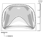
- FIG. 1 is a diagram showing the distribution of the strain ratio e x / ey , which is the ratio of the strain e x in the lateral direction of the vehicle body to the strain e y in the longitudinal direction of the vehicle body of an automobile hood panel manufactured by press molding.
- e x / ey which is the ratio of the strain e x in the lateral direction of the vehicle body to the strain e y in the longitudinal direction of the vehicle body of an automobile hood panel manufactured by press molding.
- the rolling direction of the steel plate extends along the lateral direction of the vehicle body in plan view.
- the automobile outer plate parts referred to here are arranged in the center in the left-right direction of the vehicle body, and when viewed from the vertical direction of the vehicle body, the outer shape is substantially symmetrical with respect to a straight line located in the center in the left-right direction of the vehicle body. Specifically, it refers to the hood panel, back door panel, and trunk lid of an automobile.
- the automobile outer plate component according to this embodiment is manufactured by press molding.
- the present inventors have extensively studied the influence of press molding on the presence or absence of ghost lines, and have found that the presence or absence of ghost lines and their degree change depending on the deformation mode of the blank sheet during press molding. Specifically, the more strongly the deformation mode in which the rolled steel sheet, which is the material of the blank sheet, is pulled in the sheet width direction (the direction perpendicular to the rolling direction among the directions along the sheet surface), the more likely ghost lines are generated, and the line width is reduced. The present inventors have found that large ghost lines tend to occur.
- the present inventors conjecture as follows. Elements such as Mn segregate during the solidification process of steel in the production of rolled steel sheets, which are the raw materials of blank sheets, and the segregated portions extend in the rolling direction to form bands during rolling. In the vicinity of the segregation part, the ferrite phase tends to transform into the austenite phase during annealing. The austenite phase generated during annealing becomes hard martensite after annealing. Therefore, band-like martensite extending in the rolling direction is present in the steel sheet after annealing.
- the inventors found that, as shown in FIG. , it was found that the area in which the deformation in the lateral direction of the vehicle body is larger than the deformation in the longitudinal direction of the vehicle body is dominant.
- the inventors have conducted studies based on knowledge of the above-mentioned ghost line generation mechanism based on such a deformation mode in press molding of automobile outer panel parts, and as a result, reduced ghost lines in automobile outer panel parts. I have reached the technology. That is, in the blank sheet used for automobile outer plate parts manufactured by press forming, the rolling direction of the steel plate extends along the lateral direction of the vehicle body of the automobile outer plate parts after press forming.
- the exterior panel parts for automobiles in which the strain ratio ex / ey, which is the ratio of the strain ex in the lateral direction of the car body to the strain ey in the longitudinal direction of the car body, is large are dominant. door panels and trunk lids.
- the members for example, side doors
- the members that are arranged in pairs on both sides in the left-right direction of the vehicle body
- the plate thickness direction of the steel plate extends along the Therefore, the members arranged in pairs on both sides in the left-right direction of the automobile body are not included in the technical scope of the automobile outer plate component according to the present embodiment.
- the members arranged in pairs on both sides in the left-right direction of the automobile body are included in the technical scope of the following invention, which is an invention having a common technical idea with the automobile outer panel parts according to the present embodiment.
- the technical scope of the invention of an automobile outer panel component in which the rolling direction of the steel plate extends along the vehicle body height direction It includes members arranged in pairs on both sides in the left-right direction of the automobile body.
- Both the automotive outer plate component according to the present embodiment and the automotive outer plate component according to the above invention are virtual reference Rolling of a steel plate along a direction in which the amount of deformation from a flat plate caused by press forming (the maximum amount of displacement in the normal direction from the virtual reference plane) is large, out of the first direction and the second direction along the plane that are perpendicular to each other. It has the same technical feature that the direction extends.
- the outer panel part for an automobile is a hood panel
- the longitudinal direction of the vehicle body corresponds to the first direction and the lateral direction of the vehicle body corresponds to the second direction
- the lateral direction of the vehicle body is deformed from the flat plate obtained by press molding. direction of increasing the amount.
- the longitudinal direction of the vehicle body corresponds to the first direction
- the height direction of the vehicle body corresponds to the second direction
- the height direction of the vehicle body corresponds to the flat plate obtained by press molding. This is the direction in which the amount of deformation is large.
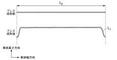
- FIG. 2 is a cross-sectional view of a blank sheet before press-molding and a press-molded article (blank sheet after press-molding) in the direction of small curvature.
- FIG. 3 is a cross-sectional view of a blank sheet before press-molding and a press-molded product in the direction of large curvature.
- the direction of rolling of the steel sheet in the outer panel parts for automobiles can be specified by observing the structure. Specifically, from the left-right direction of the vehicle body (defined as the direction of 0°) to the front direction of the vehicle body, 90° in a direction rotated counterclockwise by 15°, that is, to the front-rear direction of the vehicle body, from the vertical direction of the vehicle body. A cut section is obtained as a sample for tissue observation. Therefore, as samples for tissue observation of cut cross sections, a plurality of samples are obtained, each of which is cut from the 0° direction to the longitudinal direction of the vehicle body (90° direction) at different angles by 15°.
- the structure of the cut cross section is observed, and the cutting direction of the sample with the largest degree of segregation is taken as the rolling direction.
- the degree of segregation can be evaluated by photographing a cut cross section after nital corrosion with an optical microscope. Regions where segregation occurs appear darker than regions where segregation does not occur. Therefore, the degree of segregation can be evaluated at the position where the black line of segregation exists, using the above-mentioned difference in appearance. If it is not in the rolling direction, the black line indicating segregation exists near the center of the plate thickness, but it is not observed when it is slightly off the center. On the other hand, in the rolling direction, the black line exists not only at the thickness center but also at a position slightly away from the center. Therefore, the rolling direction can be specified as the sample in which black lines representing segregation are distributed most widely in the plate thickness direction, including the plate thickness center. In addition, before coating, the rolling direction may be specified by observing the transfer marks of the rolling rolls on the surface.
- the rolling direction of the steel plate and the lateral direction of the vehicle body match, they do not necessarily have to match. You may have for example, the angle between the rolling direction of the steel plate and the lateral direction of the vehicle body is 15° or less. Therefore, the expression that the rolling direction of the steel plate extends along the lateral direction of the vehicle body means that the angle formed by the rolling direction of the steel plate and the lateral direction of the vehicle body is 15° or less.
- the automobile outer plate component according to the present embodiment has a yield stress of 400 MPa or more when it becomes an automobile product through a vehicle assembly process, a paint baking process, and the like.
- the yield stress at the time of becoming a motor vehicle product may be called an ultimate yield stress.
- ghost lines are more likely to occur as the strength of the steel sheet increases. If the blank sheet has a yield stress (ultimate yield stress) of 400 MPa or more when it becomes an automobile product, the ghost line reduction effect is more remarkable.
- blank sheets to be press-molded for automobiles are preferably thinner in order to reduce the weight of the vehicle body, but the thinner the thickness, the lower the dent resistance.
- the ultimate yield stress of the automobile outer plate component is 400 MPa or more. More preferably, the yield stress when it becomes an automobile product is 500 MPa or more.
- the upper limit of the yield stress at the time when it becomes an automobile product is not particularly limited, but from the viewpoint of manufacturability, it is, for example, 850 MPa.
- the ultimate yield stress can be measured by the following method. That is, from the five sample acquisition positions determined as follows, a JIS13B tensile test piece is cut out in a direction perpendicular to the left-right direction of the vehicle body, a tensile test is performed according to the JIS standard, and the yield stress (yield point or 0 .2% yield stress), and the arithmetic mean of the yield stresses at these five locations.
- the sample acquisition positions will be described below.
- the x-direction and y-direction of the automobile outer panel part are defined. For example, in the case of a hood panel or a trunk lid, the x direction is the lateral direction of the vehicle body, and the y direction is the longitudinal direction of the vehicle body.
- the x direction is the lateral direction of the vehicle body
- the y direction is the vertical direction of the vehicle body.
- C 0.040-0.105%
- the C content is an element that increases strength.
- the C content is preferably 0.040% or more.
- the C content may be 0.045% or more, 0.050% or more, 0.060% or more, or 0.070% or more.
- the C content is preferably 0.105% or less.
- the C content is reduced after decarburization annealing, and the occurrence of excessive hardness difference in the decarburized layer formed near the surface is suppressed. As a result, it is possible to further reduce the occurrence of ghost lines in the outer panel parts for automobiles.
- the C content is more preferably 0.100% or less.
- the C content may be 0.095% or less, or may be 0.090% or less.
- the upper limit of the C content may be 0.085%, or may be 0.080% or less.
- the Mn content is 1.40% or less.
- the C content is preferably greater than 0.075%.
- Mn 1.00-2.30%
- Mn is an element that enhances the hardenability of steel and contributes to the improvement of strength.
- the Mn content is preferably 1.00% or more.
- the Mn content may be 1.05% or more, 1.10% or more, 1.20% or more, 1.30% or more, 1.40% or more, or It may be 1.50% or more.
- the Mn content is preferably 2.30% or less. When the Mn content is 2.30% or less, it is possible to prevent the hardness difference from easily occurring. As a result, it is possible to further reduce the occurrence of ghost lines in the outer panel parts for automobiles.
- the Mn content may be 2.10% or less.
- the Mn content when the Mn content is 2.00% or less, it is possible to reduce the occurrence of band-like Mn segregation during solidification of the steel that constitutes the outer panel parts for automobiles. As a result, it is possible to further reduce the likelihood of the difference in hardness of the steel forming the automobile outer plate component, and further reduce ghost lines in the automobile outer plate component.
- the Mn content may be 1.95% or less, 1.90% or less, 1.85% or less, 1.80% or less, 1.75% or less, or 1.70% or less may be
- Si 0.005-1.500%
- Si is an element that forms coarse Si oxides that act as starting points for destruction.
- the Si content is preferably 1.500% or less.
- the Si content is more preferably 1.300% or less or 1.000% or less, and still more preferably 0.800% or less, 0.600% or less, or 0.500% or less.
- the lower limit of the Si content may be 0%, but in order to improve the strength-formability balance, the Si content is 0.005% or more, 0.010% or more, or 0.020% or more. good too.
- Al 0.005-0.700%
- Al is an element that functions as a deoxidizer. Al is also an element that forms coarse oxides that serve as fracture starting points and embrittles the steel that constitutes the outer panel parts for automobiles. If the Al content is 0.700% or less, it is possible to further reduce the formation of coarse oxides that act as starting points of fracture, and to further suppress the tendency of the slab to crack. Therefore, the Al content is preferably 0.700% or less. The Al content is preferably 0.650% or less, 0.600% or less, 0.400% or less, 0.200% or less or 0.100%, 0.085% or less, 0.070% or less, 0.100% or less. 065% or less or 0.060% or less is more preferable.
- the lower limit of the Al content may be 0%, but the Al content may be 0.005% or more in order to sufficiently obtain the deoxidizing effect of Al.
- the Al content is preferably 0.010% or more, 0.020% or more, 0.025% or more, 0.030% or more, or 0.040% or more.
- P 0.100% or less
- P is an element that embrittles steel.
- the P content is preferably 0.100% or less.
- the P content is more preferably 0.050% or less, and still more preferably 0.030% or less or 0.020% or less.
- the lower limit of the P content may be 0%, the production cost can be further reduced by setting the P content to 0.001% or more. Therefore, the P content may be 0.001% or more.
- S 0.0200% or less
- S is an element that forms Mn sulfides and deteriorates formability such as ductility, hole expandability, stretch flangeability and bendability of the steel sheet.
- the S content is preferably 0.0200% or less.
- the S content is more preferably 0.0100% or less or 0.0080% or less, and still more preferably 0.0060% or less or 0.0040% or less.
- the lower limit of the S content may be 0%, the manufacturing cost can be further reduced by setting the S content to 0.0001% or more. Therefore, the S content may be 0.0001% or more.
- N 0.0150% or less
- N is an element that forms nitrides and deteriorates formability such as ductility, hole expandability, stretch flangeability and bendability of the steel sheet.
- the N content is preferably 0.0150% or less.
- N is also an element that causes welding defects during welding and hinders productivity. Therefore, the N content is more preferably 0.0120% or less or 0.0100% or less, and even more preferably 0.0080% or less or 0.0060% or less.
- the lower limit of the N content may be 0%, the manufacturing cost can be further reduced by setting the N content to 0.0005% or more. Therefore, the N content may be 0.0005% or more.
- O 0.0100% or less
- O is an element that forms oxides and impairs formability such as ductility, hole expandability, stretch flangeability and bendability of the steel sheet.
- the O content is preferably 0.0100% or less.
- the O content is more preferably 0.0080% or less or 0.0050% or less, and still more preferably 0.0030% or less or 0.0020% or less.
- the lower limit of the O content may be 0%, the production cost can be further reduced by making the O content 0.0001% or more. Therefore, the O content may be 0.0001% or more.
- the remainder of the chemical composition of the base steel plate that constitutes the automotive outer plate component according to the present embodiment may be Fe and impurities.
- Impurities include elements that are unavoidably mixed in from steel raw materials or scrap, elements that are unavoidably mixed in during the steelmaking process, or elements that are allowed within a range that does not impair the characteristics of the blank sheet and press-formed product according to the present embodiment. exemplified.
- Examples of impurities include H, Na, Cl, Co, Zn, Ga, Ge, As, Se, Y, Tc, Ru, Rh, Pd, Ag, Cd, In, Te, Cs, Ta, Re, Os, Ir, Pt, Au, Pb, Bi, and Po are included.
- the total amount of impurities may be 0.100% or less.
- the base steel plate that constitutes the outer panel component for automobiles according to the present embodiment may contain the following elements as arbitrary elements instead of part of Fe.
- the lower limit of the content of the following arbitrary elements is 0%.
- Cr 0-0.80% Cr is an element that enhances the hardenability of steel and contributes to an improvement in strength. Since Cr does not necessarily have to be contained, the lower limit of the Cr content may be 0%. The Cr content is preferably 0.01% or more, or 0.20% or more, and more preferably 0.30% or more in order to sufficiently obtain the strength improvement effect of Cr. In addition, when the Cr content is 0.80% or less, formation of coarse Cr carbides that may be starting points of fracture can be reduced. Therefore, the Cr content is preferably 0.80% or less. In order to reduce the alloy cost, if necessary, the Cr content is 0.60% or less, 0.40% or less, 0.20% or less, 0.10% or less, 0.06% or less, or 0.05% or less may be
- Mo 0-0.16%
- Mo is an element that suppresses phase transformation at high temperatures and contributes to improvement of strength. Since Mo does not necessarily have to be contained, the lower limit of the Mo content may be 0%.
- the Mo content is preferably 0.05% or more, and more preferably 0.10% or more, in order to sufficiently obtain the strength improvement effect of Mo.
- the Mo content is preferably 0.16% or less.
- the Mo content is 0.12% or less, 0.10% or less, 0.08% or less, 0.06% or less, 0.04% or less, or 0.02% or less may be By including both Cr: 0.01 to 0.80% and Mo: 0.01 to 0.16%, the strength of the steel sheet can be more reliably improved. Therefore, it is preferable to contain both Cr: 0.01 to 0.80% and Mo: 0.01 to 0.16%.
- Ti 0-0.100%
- Ti is an element that has the effect of reducing the S content, the N content, and the O content that form coarse inclusions that act as starting points for fracture.
- Ti has the effect of refining the structure and improving the strength-formability balance of the steel sheet. Since Ti does not necessarily have to be contained, the lower limit of the Ti content may be 0%. In order to sufficiently obtain the above effects, the Ti content is preferably 0.001% or more, more preferably 0.010% or more. Also, when the Ti content is 0.100% or less, the formation of coarse Ti sulfides, Ti nitrides and Ti oxides is reduced, and the formability of the steel sheet can be ensured. As a result, moldability can be secured.
- the Ti content is preferably 0.100% or less.
- the Ti content is preferably 0.080% or less, 0.075% or less, or 0.060% or less, and more preferably 0.040% or less, or 0.020% or less.
- the Ti content may be 0.040% or less, 0.020% or less, 0.010% or less, or 0.005% or less, as required.
- Nb is an element that contributes to the improvement of the strength of a steel sheet through strengthening by precipitates, grain refinement strengthening by suppressing the growth of ferrite grains, and dislocation strengthening by suppressing recrystallization. Since Nb does not necessarily have to be contained, the lower limit of the Nb content may be 0%. In order to sufficiently obtain the above effects, the Nb content is preferably 0.001% or more, more preferably 0.005% or more, and even more preferably 0.010% or more. Further, when the Nb content is 0.060% or less, it is possible to promote recrystallization and suppress the remaining non-recrystallized ferrite, thereby ensuring the formability of the steel sheet. As a result, moldability can be secured.
- the Nb content is preferably 0.060% or less.
- the Nb content is more preferably 0.050% or less, still more preferably 0.040% or less.
- the Nb content may be 0.030% or less, 0.020% or less, 0.015% or less, 0.010% or less, or 0.005% or less, as necessary.
- V 0-0.50%
- V is an element that contributes to the improvement of strength through strengthening by precipitates, grain refinement strengthening by suppressing the growth of ferrite crystal grains, and dislocation strengthening by suppressing recrystallization. Since V does not necessarily have to be contained, the lower limit of the V content may be 0%.
- the V content is preferably 0.01% or more, and more preferably 0.03% or more, in order to obtain a sufficient strength-enhancing effect of V. Further, when the V content is 0.50% or less, it is possible to further suppress deterioration in the formability of the steel sheet due to precipitation of a large amount of carbonitrides. As a result, deterioration of moldability is suppressed. Therefore, the V content is preferably 0.50% or less.
- the V content is 0.30% or less, 0.20% or less, 0.10% or less, 0.08% or less, 0.06% or less, 0.05% or less , 0.03% or less, or 0.02% or less.
- Ni is an element that suppresses phase transformation at high temperatures and contributes to improvement of strength. Since Ni does not necessarily have to be contained, the lower limit of the Ni content may be 0%. In order to sufficiently obtain the strength improvement effect of Ni, the Ni content is preferably 0.01% or more, more preferably 0.05% or more, and still more preferably 0.20% or more. Moreover, it can suppress that the weldability of a steel plate falls as Ni content is 1.00% or less. Therefore, the Ni content is preferably 1.00% or less.
- the Ni content is 0.70% or less, 0.60% or less, 0.50% or less, 0.40% or less, 0.30% or less, 0.20% or less , 0.15% or less, 0.10% or less, 0.08% or less, or 0.03% or less.
- Cu 0-1.00%
- Cu is an element that exists in steel in the form of fine particles and contributes to the improvement of strength. Since Cu does not necessarily have to be contained, the lower limit of the Cu content may be 0%. In order to sufficiently obtain the strength improvement effect of Cu, the Cu content is preferably 0.01% or more, more preferably 0.05% or more, and still more preferably 0.15% or more. is. Further, when the Cu content is 1.00% or less, deterioration of the weldability of the steel sheet can be further suppressed. Therefore, the Cu content is preferably 1.00% or less.
- the Cu content is 0.70% or less, 0.60% or less, 0.50% or less, 0.40% or less, 0.30% or less, 0.20% or less , 0.15% or less, 0.10% or less, 0.08% or less, or 0.03% or less.
- W 0-1.00% W is an element that suppresses phase transformation at high temperature and contributes to improvement of strength. Since W does not necessarily have to be contained, the lower limit of the W content may be 0%. In order to sufficiently obtain the strength improvement effect of W, the W content is preferably 0.01% or more, more preferably 0.03% or more, and still more preferably 0.10% or more. . In addition, when the W content is 1.00% or less, it is possible to suppress a decrease in hot workability and a decrease in productivity. Therefore, the W content is preferably 1.00% or less.
- the W content is 0.70% or less, 0.50% or less, 0.30% or less, 0.20% or less, 0.15% or less, 0.10% or less , 0.08% or less, 0.05% or less, or 0.02% or less.
- B 0 to 0.0100%
- B is an element that suppresses phase transformation at high temperature and contributes to improvement of strength. Since B does not necessarily have to be contained, the lower limit of the B content may be 0%. In order to sufficiently obtain the strength-improving effect of B, the B content is preferably 0.0001% or more, more preferably 0.0005% or more, and still more preferably 0.0010% or more. . Also, when the B content is 0.0100% or less, it is possible to suppress the formation of B precipitates and suppress the decrease in strength. Therefore, the B content is preferably 0.0100% or less. In order to reduce alloy costs, the B content may be 0.0050% or less, 0.0030% or less, 0.0020% or less, 0.0010% or less, or 0.0005% or less, as required.
- Sn 0-1.00% Sn is an element that suppresses coarsening of crystal grains and contributes to an improvement in strength. Since Sn does not necessarily have to be contained, the lower limit of the Sn content may be 0%. In order to sufficiently obtain the effect of Sn, the Sn content is preferably 0.01% or more. Moreover, when the Sn content is 1.00% or less, it is possible to prevent the steel sheet from embrittlement and breakage during rolling. Therefore, the Sn content is preferably 1.00% or less. In order to reduce alloy costs, the Sn content may be 0.50% or less, 0.20% or less, 0.10% or less, 0.05% or less, or 0.02% or less, as required.
- Sb 0-0.200%
- Sb is an element that suppresses coarsening of crystal grains and contributes to an improvement in strength. Since Sb does not necessarily have to be contained, the lower limit of the Sb content may be 0%. In order to sufficiently obtain the above effects, the Sb content is preferably 0.001% or more, more preferably 0.005% or more. Moreover, when the Sb content is 0.200% or less, it is possible to prevent the steel sheet from embrittlement and breakage during rolling. Therefore, the Sb content is preferably 0.200% or less. In order to reduce alloy costs, the Sb content may be 0.100% or less, 0.070% or less, 0.040% or less, 0.010% or less, or 0.005% or less, as necessary.
- Ca, Mg, Zr, and REM are elements that contribute to improving the formability of steel sheets. Since Ca, Mg, Zr and REM do not necessarily have to be contained, the lower limit of the total content of these elements includes 0%. In order to sufficiently obtain the effect of improving formability, the content of each of these elements is preferably 0.0001% or more, more preferably 0.0010% or more. In order to sufficiently obtain the above effect, it is not necessary to contain all of the above elements, and the content of any one of the above elements should be 0.0001% or more.
- the content of each of Ca, Mg, Zr and REM is 0.0100% or less, it is possible to suppress the decrease in ductility of the steel sheet. Therefore, the content of each of these elements is set to 0.0100% or less. Preferably, it is 0.0050% or less. In order to reduce the alloy cost, if necessary, the content of Ca, Mg, Zr and REM may be 0.0030% or less, 0.0020% or less, 0.0010% or less, or 0.0003% or less. good.
- REM Rotary Earth Metal
- REM refers to a total of 17 elements consisting of Sc, Y and lanthanoids
- the REM content refers to the total content of these elements.
- the chemical composition of the base steel plate that constitutes the above-mentioned automobile outer panel parts can be measured by a general analysis method.
- it may be measured using ICP-AES (Inductively Coupled Plasma-Atomic Emission Spectrometry).
- C and S may be measured using the combustion-infrared absorption method, N using the inert gas fusion-thermal conductivity method, and O using the inert gas fusion-nondispersive infrared absorption method.
- the chemical composition of the base steel plate constituting the automotive outer plate component is, in mass%, C: 0.040 to 0.105%, Mn: 1.00-2.30%, Si: 0.005 to 1.500%, Al: 0.005 to 0.700%, P: 0.100% or less, S: 0.0200% or less, N: 0.0150% or less, O: 0.0100% or less, Cr: 0 to 0.80%, Mo: 0-0.16%, B: 0 to 0.0100%, Ti: 0 to 0.100%, Nb: 0 to 0.060%, V: 0 to 0.50%, Ni: 0 to 1.00%, Cu: 0 to 1.00%, W: 0 to 1.00%, Sn: 0 to 1.00%, Sb: 0 to 0.200%, Ca: 0 to 0.0100%, Mg: 0-0.0100%, Zr: 0 to 0.0100%,
- REM 0 to 0.0100%
- Mg 0-0.0100%
- Zr 0 to 0.0
- the chemical composition of the base steel plate constituting the automotive outer panel component according to the present embodiment is within the above range, a blank sheet having high strength and reduced segregation can be obtained. As a result, the automobile outer panel parts obtained by pressing such a blank sheet have even more reduced ghost lines and have much better appearance quality.
- the automotive outer plate component according to the present embodiment may have a plating layer on at least one surface of the base steel plate that constitutes the automotive outer plate component.
- the plated layer includes a zinc plated layer, a zinc alloy plated layer, and an alloyed zinc plated layer and an alloyed zinc alloy plated layer obtained by subjecting these to an alloying treatment.
- the zinc plating layer and the zinc alloy plating layer include Al, Ag, B, Be, Bi, Ca, Cd, Co, Cr, Cs, Cu, Ge, Hf, Zr, I, K, La, Li, Mg, Mn, One or more of Mo, Na, Nb, Ni, Pb, Rb, Sb, Si, Sn, Sr, Ta, Ti, V, W, Zr, and REM are used to improve corrosion resistance and formability of automobile outer panel parts. may be contained within a range that does not inhibit the In particular, Ni, Al and Mg are effective in improving corrosion resistance.
- the Al content of the galvanized layer is 0.5% by mass or less, the adhesion between the surface of the steel sheet and the galvanized layer can be sufficiently ensured, so the Al content of the galvanized layer is 0.5%. % by mass or less is preferable.
- the zinc plating layer and the zinc alloy plating layer are formed by a hot dip plating method, an electroplating method, or a vapor deposition plating method.
- the galvanized layer is a hot-dip galvanized layer formed by a hot-dip galvanizing method
- the Fe content of the hot-dip galvanized layer is preferably 3.0% by mass or less in order to increase the adhesion between the steel sheet surface and the hot-dip galvanized layer.
- the galvanized layer is an electrogalvanized layer formed by an electroplating method
- the Fe content of the electrogalvanized layer is preferably 0.5% by mass or less from the viewpoint of improving corrosion resistance.
- the coating layer is a galvannealed layer or a galvannealed layer obtained by subjecting a hot-dip galvanized layer or a galvannealed layer to an alloying treatment
- the surface of the steel sheet and the galvannealed layer or alloyed layer is preferably 7.0 to 13.0% by mass.
- Fe is incorporated into the galvanized layer and the Fe content is increased.
- the Fe content can be made 7.0% by mass or more. That is, the zinc plating layer having an Fe content of 7.0% by mass or more is a zinc alloying layer or a zinc alloying plating layer.
- the Al content and Fe content in the plating layer can be obtained by the following method. Only the plated layer is dissolved and removed using a 5% by volume HCl aqueous solution containing an inhibitor. The Fe content (% by mass) in the plating layer is obtained by measuring the Fe content in the resulting solution using ICP-AES.
- the chemical composition of the base steel sheet in the case where the outer panel parts for automobiles have a plating layer can be analyzed after removing the plating layer on the surface by mechanical grinding.
- the thickness of the base steel plate constituting the outer panel parts for automobiles is 0.2 to 5.0 mm.
- the base material steel plate which comprises the outer panel parts for motor vehicles is provided with a plating layer, it is the thickness including a plating layer.
- the thickness of the base steel plate that constitutes the outer panel part for automobiles depends on the thickness of the steel plate to be blanked. A steel plate having a thickness of 0.2 mm or more can easily maintain its flat shape, and can improve dimensional accuracy and shape accuracy during blanking. Therefore, the base steel plate that constitutes the outer panel parts for automobiles having a thickness of 0.2 mm or more has high dimensional accuracy and shape accuracy.
- the thickness of the base steel plate that constitutes the outer panel parts for automobiles is preferably 0.2 mm or more. More preferably, the thickness of the base steel plate that constitutes the outer panel component for automobiles is 0.4 mm or more.
- the thickness of the steel sheet to be blanked is 5.0 mm or less, it becomes easy to perform appropriate strain application and temperature control in the manufacturing process, and a homogeneous structure can be obtained. Therefore, the structure of the base steel sheet forming the outer panel parts for automobiles having a thickness of 5.0 mm or less becomes more homogeneous. Therefore, the thickness of the base steel plate that constitutes the outer panel parts for automobiles is preferably 5.0 mm or less.
- the thickness of the base steel plate that constitutes the outer panel component for automobiles is 4.5 mm or less. From the viewpoint of reducing the weight of automobiles, the thickness of the base steel plate constituting the outer panel parts for automobiles is more preferably 0.7 mm or less, more preferably 0.6 mm or less, and more preferably 0.5 mm or less. There may be. So far, the automobile outer plate component according to the present embodiment has been described.
- the blank sheet that is the raw material for the automobile outer plate component according to the present embodiment is not particularly limited, but is preferably the blank sheet described later.
- An example of a blank sheet that is used as a material for the automotive outer panel component according to the present embodiment will be described below.
- a blank sheet according to the present embodiment is a material for automobile outer panel parts manufactured by press forming, and is a blank sheet including a steel plate, the rolling direction of the steel plate extending along the longitudinal direction of the blank sheet. , a thickness of 0.6 mm or less.
- the blank sheet according to the present embodiment can be used for the above-described automobile outer panel parts.
- the blank sheet according to the present embodiment preferably has the same chemical composition as that of the steel sheet that constitutes the outer panel parts for automobiles described above, and may have the above-described plated layer on at least one surface.
- the arithmetic mean waviness Wa 0.10 to 0.30 ⁇ m
- the smaller the arithmetic mean waviness Wa of the blank sheet the more preferable it is from the viewpoint of appearance quality. This is because if the surface roughness is excessively large, the appearance quality is poor.
- the present invention has found that the occurrence of ghost lines can be further reduced by appropriately roughening the surface of the blank sheet to the extent that the appearance quality is not degraded. they found out. Therefore, the arithmetic mean waviness Wa of the blank sheet according to this embodiment is preferably 0.10 ⁇ m or more.
- the arithmetic mean waviness Wa of the blank sheet according to this embodiment is more preferably 0.13 ⁇ m or more. Further, the present inventors have found that if the arithmetic mean waviness Wa is 0.30 ⁇ m or less, the appearance quality of the blank sheet and the outer panel parts for automobiles can be improved. Therefore, the arithmetic mean waviness Wa is preferably 0.30 ⁇ m or less. The arithmetic mean waviness Wa of the blank sheet according to this embodiment is more preferable. It is 0.25 ⁇ m or less.
- the arithmetic mean waviness Wa is the arithmetic mean waviness of the steel sheet when the blank sheet does not have a plating layer, and the arithmetic mean waviness of the plating layer when the blank sheet has a plating layer on the surface.
- the arithmetic mean waviness Wa is obtained by the following method.
- a test piece of 50 mm ⁇ 50 mm is cut out from a position 10 mm or more away from the end face of the blank sheet.
- a laser displacement measuring device Keyence VK-X1000
- three lines of the profile are measured along the direction perpendicular to the rolling direction.
- an undulation curve is obtained by sequentially applying contour filters with cutoff values ⁇ c and ⁇ f to the cross-sectional curve according to JIS B 0601:2013.
- a wave curve is obtained by removing a component with a wavelength ⁇ c of 0.8 mm or less and a component with a wavelength ⁇ f of 2.5 mm or more from the obtained measurement results.
- the arithmetic mean undulation is calculated according to JIS B 0601:2013, and the average value of a total of 3 lines is calculated.
- the arithmetic mean of the calculated average values of the three lines is taken as the arithmetic mean waviness Wa of the steel plate.
- the blank sheet according to the present embodiment has a chemical composition of the base steel plate constituting the blank sheet, in mass%, C: more than 0.075%, 0.100% or less, Mn: 1.00-1.40%, Si: 0.005 to 1.500%, P: 0.100% or less, S: 0.0200% or less, Al: 0.005 to 0.700%, N: 0.0150% or less, O: 0.0100% or less, Cr: 0 to 0.80%, Mo: 0-0.16%, B: 0 to 0.0100%, Ti: 0 to 0.100%, Nb: 0 to 0.060%, V: 0 to 0.50%, Ni: 0 to 1.00%, Cu: 0 to 1.00%, W: 0 to 1.00%, Sn: 0 to 1.00%, Sb: 0 to 0.200%, Ca: 0 to 0.0100%, Mg: 0-0.0100%, Zr: 0
- the band-like Mn segregation is reduced. This suppresses the formation of martensite due to annealing, and suppresses the increase in hardness difference.
- a blank sheet in which the difference in hardness is suppressed further reduces the generation of ghost lines when press-molded. Furthermore, if the arithmetic mean waviness Wa is 0.10 to 0.30 ⁇ m, even better appearance quality can be obtained.
- the blank sheet according to the present embodiment has a chemical composition of the base steel plate constituting the blank sheet, in mass%, C: 0.040 to 0.075%, Mn: 1.00-2.00%, Si: 0.005 to 1.500%, P: 0.100% or less, S: 0.0200% or less, Al: 0.005 to 0.700%, N: 0.0150% or less, O: 0.0100% or less, Cr: 0 to 0.80%, Mo: 0-0.16%, B: 0 to 0.0100%, Ti: 0 to 0.100%, Nb: 0 to 0.060%, V: 0 to 0.50%, Ni: 0 to 1.00%, Cu: 0 to 1.00%, W: 0 to 1.00%, Sn: 0 to 1.00%, Sb: 0 to 0.200%, Ca: 0 to 0.0100%, Mg: 0-0.0100%, Mg: 0-0.0100%
- ⁇ C indicates the C concentration gradient in the region from 20 ⁇ m deep from the surface to 60 ⁇ m deep from the surface.
- a sharp increase in the C concentration gradient in the decarburized layer can be suppressed by setting ⁇ C to 0.20 to 0.90% by mass/mm. As a result, it is possible to suppress the occurrence of ghost lines after press molding.
- ⁇ C is preferably 0.20 mass %/mm or more.
- ⁇ C is more than 0.90% by mass/mm, the difference in hardness within the decarburized layer becomes significant, and it may be difficult to suppress the occurrence of ghost lines.
- ⁇ C is more preferably 0.30 mass %/mm or more, 0.35 mass %/mm or more, 0.40 mass %/mm or more, or 0.45 mass %/mm or more. Also, ⁇ C is preferably 0.80 mass %/mm or less or 0.75 mass %/mm or less.
- the "surface” in “20 ⁇ m depth position from the surface” and “60 ⁇ m depth position from the surface” refers to the interface between the plating layer and the base material.
- the depth position where the Fe content is 95% by mass or more is regarded as the interface between the plating layer and the base material.
- the reason why ⁇ C is specified at a depth position of 20 ⁇ m or more from the surface is that the C concentration at a depth of less than 20 ⁇ m from the surface does not affect ghost lines.
- ⁇ C is obtained by the following method. Measure the C content (% by mass) from the surface of the steel sheet to 100 ⁇ m in the depth direction (plate thickness direction) by Glow Discharge Optical Emission Spectrometry (GDS analysis) for any three locations on the steel sheet. do. ⁇ C (% by mass/mm) is calculated from the C content (C 20 ) at a depth of 20 ⁇ m from the surface, the C content (C 60 ) at a depth of 60 ⁇ m from the surface, and the above formula (1). . ⁇ C is obtained by calculating the average value of ⁇ C at three locations. For the measurement, a Marcus type high-frequency glow discharge luminescence surface analyzer (GD-Profiler) manufactured by Horiba, Ltd. is used.
- GD-Profiler high-frequency glow discharge luminescence surface analyzer
- the blank sheet according to the present embodiment has a chemical composition of the base steel sheet that constitutes the blank sheet, in mass%, C: 0.040 to 0.105%, Mn: 1.00-2.30%, Si: 0.005 to 1.500%, Al: 0.005 to 0.700%, P: 0.100% or less, S: 0.0200% or less, N: 0.0150% or less, O: 0.0100% or less, Cr: 0 to 0.80%, Mo: 0-0.16%, Ti: 0 to 0.100%, B: 0 to 0.0100%, Nb: 0 to 0.060%, V: 0 to 0.50%, Ni: 0 to 1.00%, Cu: 0 to 1.00%, W: 0 to 1.00%, Sn: 0 to 1.00%, Sb: 0 to 0.200%, Ca: 0 to 0.0100%, Mg: 0-0.0100%, Zr: 0 to 0.0100%, REM: 0
- the chemical composition of the base steel plate constituting the blank sheet according to the present embodiment is within the above range and ⁇ C is 0.20 to 0.90% by mass/mm, the hardness difference in the decarburized layer is can be reduced. As a result, the automobile outer panel parts obtained by pressing such a blank sheet have even more reduced ghost lines and have much better appearance quality.
- the blank sheet according to the present embodiment has an arithmetic mean waviness Wa of 0.10 to 0.30 ⁇ m and a ⁇ C of 0.20 to 0.90% by mass/mm. good too.
- the yield stress of the blank sheet may change during the automobile manufacturing process such as the vehicle assembly process and the paint baking process, but if it is 240 MPa or more, the ultimate yield stress will be about 400 MPa or more. Therefore, the blank sheet preferably has a yield stress of 240 MPa or more.
- the yield stress of the blank sheet is more preferably 300) MPa or more.
- the upper limit of the yield stress of the blank sheet is not particularly limited, and may be, for example, 350 MPa or 450 MPa.
- the blank sheet preferably has a tensile strength of 440 MPa or more.
- the tensile strength of the blank sheet is more preferably 500 MPa or higher, more preferably 550 MPa or higher or 600 MPa or higher. Further, by setting the tensile strength to 750 MPa or less, it is possible to suppress deterioration of the appearance after press molding. Therefore, the blank sheet preferably has a tensile strength of 750 MPa or less.
- the tensile strength of the blank sheet is more preferably 700 MPa or less.
- the tensile strength of the blank sheet is evaluated according to JIS Z 2241:2011.
- the test piece shall be JIS Z 2241:2011 No. 5 test piece.
- a tensile test piece is taken from a quarter of the widthwise direction (the direction perpendicular to the rolling direction on the surface of the blank sheet) from the end, and the longitudinal direction is the direction perpendicular to the rolling direction.
- the tensile strength is evaluated according to JIS Z 2241:2011.
- the test piece shall be JIS Z 2241:2011 No. 5 test piece.
- Tensile test pieces are taken from the 1/4 part from the edge in the width direction, and the direction perpendicular to the rolling direction is taken as the longitudinal direction.
- the thickness of the blank sheet according to this embodiment is 0.6 mm or less. From the viewpoint of reducing the weight of automobiles, the thickness of the blank sheet is more preferably 0.5 mm or less.
- the lower limit of the thickness of the blank sheet is not particularly limited, and the thickness of the blank sheet can be, for example, 0.2 mm or more. From the viewpoint of ensuring strength, the thickness of the blank sheet is preferably 0.4 mm or more.
- the thickness of a steel plate used for a frame member of an automobile, such as a cross member is 1.0 mm or more from the viewpoint of securing strength.
- the blank sheet according to the present embodiment is used for automobile outer panel parts, and has a different thickness from steel plates used for automobile frame members.
- the shape of the blank sheet according to the present embodiment is substantially symmetrical, and is, for example, a trapezoid, a rectangle, a polygon such as a hexagon, or the like.
- the direction perpendicular to the axis of symmetry is along the rolling direction.
- the direction perpendicular to the axis of symmetry corresponds to the longitudinal direction of the blank sheet. It is preferable that the direction perpendicular to the axis of symmetry and the rolling direction match, but they do not necessarily have to match. and may have an angle. For example, the angle between the direction perpendicular to the axis of symmetry and the rolling direction is 15° or less.
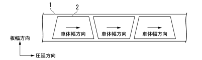
- FIG. 4 is a diagram showing an example of blanking directions in the blank sheet manufacturing method according to the present embodiment.
- a method for manufacturing a blank sheet according to the present embodiment is a method for manufacturing a blank sheet including a steel plate, wherein the steel plate is blanked so that the rolling direction of the steel plate extends along the longitudinal direction of the blank sheet.
- Blanking here means punching using a die or the like and cutting out using a shear from a blank sheet as a material.
- the manufacturing method of the rolled steel plate which is the material of the blank sheet
- the manufacturing method of the rolled steel plate which is the raw material of the blank sheet described below is merely an example, and the manufacturing method is not limited to the manufacturing method described below.
- the winding temperature is more preferably 600°C or higher, and even more preferably 650°C or higher.
- (II) Pickling Time 50 Seconds or More When the pickling time is set to 50 seconds or more after coiling and before cold rolling, unevenness is likely to occur on the surface of the steel sheet. More preferably, the pickling time is 70 seconds or more.
- the surface of the steel sheet can be formed with appropriate unevenness during cold rolling. More preferably, the arithmetic mean roughness Ra of the rolling rolls is 0.3 ⁇ m or more. Note that the arithmetic mean roughness Ra is the arithmetic mean roughness.
- a slab which is the material of the steel plate, may be heated in a temperature range of 1100° C. or more and less than 1200° C. for 30 minutes. After heating the slab, it is hot rolled. After hot rolling, coiling is performed, and then pickling is performed. Cold rolling is performed after pickling. The cumulative rolling reduction in cold rolling is preferably 30 to 90%. Annealing is performed after cold rolling. After that, the plating layer described above is formed as necessary. Moreover, it is preferable to perform temper rolling after that.
- decarburization annealing may be performed on the cold-rolled steel sheet obtained by the above method.
- the dew point during decarburization annealing is -20 ° C. or higher
- the residence time of the steel plate in the temperature range of 700 ° C. or higher is 50 to 400 seconds.
- the upper limit of the dew point is not particularly defined, it is generally about 10°C. If the dew point is too low or the residence time is too short, decarburization will not proceed sufficiently. Also, if the residence time is too long, sufficient tensile strength may not be obtained.
- the temperature during annealing is, for example, about 750 to 850.degree.
- a steel sheet having an arithmetic mean waviness Wa of 0.10 to 0.30 ⁇ m can be manufactured by the first manufacturing method described above.
- a hot-rolled steel sheet is obtained by subjecting a slab having the chemical composition described above to hot rolling under general conditions.
- the obtained hot-rolled steel sheet is subjected to primary annealing in a high temperature range in the atmosphere.
- This primary annealing is performed under conditions of an annealing temperature of 550 to 700° C. and an annealing time of 2 hours or more.
- annealing temperature is less than 550° C. or the annealing time is less than 2 hours, it may not be possible to preferably control the ⁇ C of the steel sheet.
- the steel is pickled and then cold-rolled with a cumulative rolling reduction of 70% or more to produce a steel plate or strip having a desired thickness.
- a cumulative reduction ratio of cold rolling to 70% or more, austenite recrystallization is promoted during annealing after cold rolling, and an increase in the austenite fraction can be suppressed.
- the ferrite fraction which has a large C diffusion coefficient, increases during annealing after cold rolling, promoting decarburization.
- the dew point during secondary annealing (average dew point in the annealing furnace) is -10 ° C. or higher, and the residence time of the steel plate in the temperature range of 700 ° C. or higher is 50 to 400 seconds. can be used to decarburize the surface of the steel sheet.
- the upper limit of the dew point is not particularly defined, it is generally about 10°C. If the dew point is too low or if the residence time is too short, decarburization will not proceed sufficiently, and ⁇ C cannot be controlled favorably. Moreover, when the residence time is too long, sufficient tensile strength may not be obtained.
- the temperature during annealing is, for example, about 750 to 850.degree.
- Conditions other than those mentioned above are not particularly limited.
- a slab which is the material of the steel sheet, may be heated to a temperature range of 1100° C. or higher and then hot rolled. If necessary, the plating layer described above may be formed.
- a steel sheet having a ⁇ C of 0.20 to 0.90% by mass/mm can be manufactured by the second manufacturing method described above.
- a rolled steel plate which is a blank sheet material manufactured by the above method, is blanked so that the rolling direction of the steel plate extends along the lateral direction of the vehicle body of the outer panel parts for automobiles.
- the example shown in FIG. 4 is an example in which a blank sheet 2 is punched out from a rolled steel plate 1, which is a blank sheet material, using a blanking press device.
- the blank sheet 2 has a substantially trapezoidal shape, and is punched so that two substantially parallel sides of the substantially trapezoidal shape extend in the rolling direction of the rolled steel plate 1, which is the material of the blank sheet.
- the direction in which the two substantially parallel sides extend is the lateral direction of the vehicle body.
- blank sheets 2 are punched out at arbitrary intervals. Further, when blanking is performed by a shear having a mechanism for cutting at an arbitrary angle (a so-called turn shear), the blank sheet 2 is cut so as to reduce the amount of offcuts without leaving an interval. It is cut out from a rolled steel plate 1 as a raw material.
- the technique described in Patent Document 2 is a technique for improving the yield when manufacturing a cylindrical container using a long metal plate as a raw material, and cannot be applied to the manufacture of outer panel parts for automobiles.
- blanking is performed so that the longitudinal direction of the vehicle body when press-molded is aligned with the rolling direction of the steel plate.
- the blank sheet manufacturing method according to the present embodiment unlike the above, the blank sheet material is rolled so that the rolling direction of the steel plate extends along the lateral direction of the vehicle body of the automobile outer plate component. Blanking a steel plate. Therefore, there is a possibility that the manufacturing yield of the blank sheet according to the present embodiment will decrease.
- the blank sheet manufacturing method according to the present embodiment as shown in FIG. 4, it is preferable that the blanking directions of the blank sheets 2 are staggered.
- the blanking directions of the blank sheets 2 are preferably staggered, but the blanking directions may be the directions in which the blank sheets 2 have the same posture.
- blanking may be performed so that the short side of the two substantially parallel sides is arranged on one end side of the rolled steel plate that is the material of the blank sheet. good.
- the blanking may be performed so that the shape of the blank sheet 2 is substantially line symmetrical, for example, rectangular.
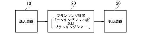
- FIG. 5 is a block diagram showing an example of a blank sheet manufacturing facility according to an embodiment of the present invention.
- the blank sheet manufacturing facility includes a feeding device 10 , a blanking device 20 and a storage device 30 .
- the feeding device 10 is a device that feeds the rolled steel plate, which is the blank sheet material, into the blanking device 20 .
- the feeding device 10 is not particularly limited, and may be a feeding device provided in a known blanking facility.
- the feeding device 10 may include at least one of an unwinding device for unwinding the coil, a leveling device for flattening the unwound coil, and a cutting device for cutting the flattened steel strip to a predetermined size. good.
- the rolled steel plate that is the raw material of the blank sheet inserted by the feeding device 10 may be a leveled steel strip, or a long steel plate (strip) obtained by cutting the steel strip into a predetermined length. may A rolled steel plate, which is the material of this blank sheet, is processed by a blanking device 20 .
- the blanking device 20 is a device for blanking the steel plate so that the rolling direction of the steel plate extends along the longitudinal direction of the blank sheet.
- the blanking device 20 is, for example, a blanking shear having a shear for cutting a blank sheet from a steel plate that is a blank sheet material, or a blanking press machine having a die for punching a blank sheet from the steel plate.
- the blanking device 20 blanks the steel plate so that the rolling direction of the steel plate extends along the lateral direction of the automobile body. If the blanking device 20 is a blanking shear, the shear is preferably a Turnsher for cutting the blank sheets alternately from the rolled steel plate. Further, when the blanking device 20 is a blanking press machine, it is preferable to alternately arrange two dies in order to alternately punch out blank sheets from the rolled steel plate.
- the storage device 30 is a device for stacking blank sheets.
- the storage device 30 is not particularly limited, and may be a storage device provided in a known blanking facility.
- the storage device 30 may have, for example, transfer means for transferring the blank sheets obtained by the blanking device 20 and a storage section for stacking and storing the blank sheets.
- the configuration of the blank sheet manufacturing equipment according to the present embodiment is not limited to the configuration described above, and may further include a known configuration as necessary. can be
- press molding may be performed by aligning the rolling direction of the steel plate in the blank sheet along the lateral direction of the vehicle body.
- press forming for example, after pressing a blank sheet with a blank holder and a die, it is possible to form by applying strain to a steel plate by pressing a punch against it and stretching it. Such forming is called draw forming or stretch forming.
- the inventors verified the effect of reducing ghost lines by the chemical composition, arithmetic mean waviness Wa, and ⁇ C of the blank sheet.
- the conditions in the examples are examples of conditions adopted for confirming the feasibility and effect of the present invention.
- the present invention is not limited to this one conditional example. Various conditions can be adopted in the present invention as long as the object of the present invention is achieved without departing from the gist of the present invention.
- Example 1 A steel having the chemical composition shown in Table 1 was melted, and a slab having a thickness of 240 to 300 mm was produced by continuous casting. Using the obtained slabs, cold-rolled steel sheets and plated steel sheets were manufactured under conditions (I) to (VI) described later. In Table 2, when the conditions were satisfied, "OK” was written in the condition column, and when the conditions were not satisfied, "NG” was written in the condition column. The thickness of the obtained steel sheet and plated steel sheet was 0.2 to 2.0 mm.
- annealing was performed after cold rolling.
- Manufacturing conditions other than conditions (I) to (VI) were as follows. After heating the slab to a temperature range of 1100° C. or higher, it was hot rolled. After hot rolling, coiling was performed, and then pickling was performed. After pickling, cold rolling was performed with a cumulative rolling reduction of 30 to 90%. Annealing was performed after cold rolling to form an alloyed hot-dip galvanized layer (GA), a hot-dip galvanized layer (GI), and an electroplated layer (EG) as necessary. After that, temper rolling was performed.
- GA alloyed hot-dip galvanized layer
- GI hot-dip galvanized layer
- EG electroplated layer
- Conditions (I) to (VI) in the table are as follows.
- the winding temperature is set to 550° C. or higher.
- the pickling time shall be 50 seconds or longer.
- Arithmetic mean roughness Ra of the roll surface in the final pass of cold rolling is set to 0.2 to 0.7 ⁇ m.
- the reduction ratio of temper rolling is set to 0.3 to 0.7%, and the arithmetic mean roughness Ra of the rolling rolls is set to 1.5 to 3.5 ⁇ m.
- the slab is heated to a temperature range of 1200° C. or higher and held in the temperature range for 5 hours or longer.
- Annealing is performed with a dew point (average dew point in the annealing furnace) of ⁇ 20° C. or higher and a residence time of the steel sheet in a temperature range of 700° C. or higher for 50 to 400 seconds.
- a substantially semi-cylindrical simulated part (press-molded product) simulating a door outer was manufactured by press-molding.
- the material steel plate or plated steel sheet
- strain in any direction along the surface of the simulated part is applied at any position on the surface of the simulated part.
- the ratio of the strain in the direction perpendicular to the direction (any direction thereof) to the strain was set to about 1. In other words, press molding was performed so that strain anisotropy did not occur at any position on the surface of the simulated part. Therefore, in this embodiment, how the ghost lines of the simulated part are generated does not depend on the orientation of the blank sheet.
- the arithmetic mean waviness Wa and tensile strength were obtained by the above-described methods.
- the obtained tensile strength was 500 MPa or more, it was determined to be high strength and passed. On the other hand, when the obtained tensile strength was less than 500 MPa, it was determined to be unacceptable because the strength was inferior.
- the average value ⁇ of the Mn concentration and the standard deviation ⁇ of the Mn concentration were obtained by the following methods. After the thickness cross-section of the base steel plate was mirror-polished, the Mn concentration was measured at 600 points at predetermined depth positions in the rolling direction of the base steel plate at intervals of 1 ⁇ m. By calculating the average value of the obtained Mn concentrations, the Mn concentration (% by mass) at a predetermined depth position was obtained. This operation is performed every 1 ⁇ m in the plate thickness direction from the position 1/8 of the plate thickness in the plate thickness direction from the surface of the base steel plate to the position 3/8 of the plate thickness in the plate thickness direction from the surface. gone.
- the average value ⁇ of the Mn concentration was obtained.
- the standard deviation ⁇ of the Mn concentration was obtained by calculating the standard deviation from all the obtained Mn concentrations.
- the apparatus used was an electron probe microanalyzer (EPMA), and the measurement conditions were an acceleration voltage of 15 kV. When (3 ⁇ / ⁇ ) ⁇ 100 is 7.0 or less, Mn segregation in the base steel sheet is significantly reduced.
- the thickness of the decarburized layer was obtained by the following method. At three arbitrary points on the base steel sheet, the C concentration in the region from the surface of the base steel sheet to a position 1/2 the thickness in the depth direction (thickness direction) was measured every 1 ⁇ m depth. The thickness of the decarburized layer was obtained by regarding the region where the C concentration was 1/2 or less of the C concentration at the position away from the surface by 1/2 of the plate thickness as the decarburized layer, and determining the thickness of the decarburized layer. For the measurement, a Marcus-type high-frequency glow discharge luminescence surface analyzer (GD-Profiler) manufactured by Horiba, Ltd. was used.
- GD-Profiler high-frequency glow discharge luminescence surface analyzer
- the appearance quality of the simulated parts was evaluated by the following method. Appearance quality was evaluated by the degree of ghost lines generated on the surface of the simulated part after molding.
- the surface after press molding was ground with a grindstone, and striped patterns at intervals of several millimeters on the surface were judged to be ghost lines, and were rated on a scale of 1 to 5 depending on the degree of occurrence of the striped pattern.
- An arbitrary area of 100 mm x 100 mm was visually checked, and the case where no streak pattern was confirmed was rated as "1", and the case where the maximum length of the streak pattern was 20 mm or less was rated as "2", and the maximum length of the streak pattern.
- Wz is the sum of the maximum peak height Zp and the maximum valley height Zv of the undulation curve.
- a waviness curve of the surface of the press-molded product (simulated part) was obtained in accordance with JIS B 0601:2013 by the same method as that used to obtain the arithmetic mean waviness Wa. From this undulation curve, the maximum peak height Zp and the maximum valley height Zv were obtained, and Wz was obtained by calculating the sum of these. When the obtained Wz was 0.40 ⁇ m or less, it was judged that the appearance quality was superior.
- the chemical composition of the base steel sheet is, in mass%, C: 0.040 to 0.100%, Mn: 1.00 to 2.00%, Si: 0.005 to 1.500%. , P: 0.100% or less, S: 0.0200% or less, Al: 0.005-0.700%, N: 0.0150% or less, O: 0.0100% or less, Cr: 0-0.
- Example 2 A steel having the chemical composition shown in Table 3 was melted, and a slab with a thickness of 240 to 300 mm was produced by continuous casting. After heating the obtained slab to a temperature range of 1100° C. or higher, hot rolling was performed. After hot rolling, coiling was performed, primary annealing was performed under the conditions shown in Table 4, and then pickling was performed. The finish rolling temperature of hot rolling was set to 900°C or higher, and the coiling temperature was set to 650°C or lower. After pickling, cold rolling was performed with a cumulative rolling reduction of 70 to 90%.
- simulated parts were manufactured by press forming using steel sheets and plated steel sheets (blank sheets).
- the material steel sheet or plated steel sheet
- press forming was performed so that no strain anisotropy occurred at any position on the surface of the simulated part. rice field. Therefore, also in this embodiment, the manner in which ghost lines are generated in the simulated part does not depend on the orientation of the blank sheet.
- ⁇ C was obtained for the obtained steel sheets, plated steel sheets and simulated parts (press-formed parts) by the method described above. Since ⁇ C of the steel plate and plated steel sheet and ⁇ C of the simulative component were the same value, ⁇ C of the simulative component is not shown in the table. Also, the tensile strength of the steel plate and the appearance quality of the simulated parts were evaluated by the following methods. Since there is no significant difference between the tensile strength of the steel plate and the tensile strength of the simulated part (press-formed product), it was evaluated whether or not the steel plate had the tensile strength desired for the door outer. .
- the chemical composition of the base steel sheet is, in mass%, C: 0.040 to 0.105%, Mn: 1.00 to 2.30%, Si: 0.005 to 1.500%. , Al: 0.005-0.700%, P: 0.100% or less, S: 0.0200% or less, N: 0.0150% or less, O: 0.0100% or less, Cr: 0-0.
- an automobile outer panel component with reduced ghost lines a blank sheet capable of reducing ghost lines due to press molding, a blank sheet manufacturing method, and a blank sheet manufacturing facility. can.
Landscapes
- Chemical & Material Sciences (AREA)
- Engineering & Computer Science (AREA)
- Mechanical Engineering (AREA)
- Materials Engineering (AREA)
- Metallurgy (AREA)
- Organic Chemistry (AREA)
- Crystallography & Structural Chemistry (AREA)
- Thermal Sciences (AREA)
- Physics & Mathematics (AREA)
- Combustion & Propulsion (AREA)
- Transportation (AREA)
- Heat Treatment Of Sheet Steel (AREA)
- Shaping Metal By Deep-Drawing, Or The Like (AREA)
Abstract
Description
[1] 本発明の一態様に係る自動車用外板部品は、鋼板を備える自動車用外板部品であって、平面視で、車体左右方向に沿って前記鋼板の圧延方向が延在している。
[2] 上記[1]に記載の自動車用外板部品は、到達降伏応力が400MPa以上であってもよい。
[3] 上記[1]又は上記[2]に記載の自動車用外板部品は、前記鋼板の化学組成が、質量%で、
C :0.040~0.105%、
Mn:1.00~2.30%、
Si:0.005~1.500%、
Al:0.005~0.700%、
P :0.100%以下、
S :0.0200%以下、
N :0.0150%以下、
O :0.0100%以下、
Cr:0~0.80%、
Mo:0~0.16%、
B :0~0.0100%、
Ti:0~0.100%、
Nb:0~0.060%、
V :0~0.50%、
Ni:0~1.00%、
Cu:0~1.00%、
W :0~1.00%、
Sn:0~1.00%、
Sb:0~0.200%、
Ca:0~0.0100%、
Mg:0~0.0100%、
Zr:0~0.0100%、
REM:0~0.0100%、並びに
残部:Fe及び不純物であってもよい。
[4] 本発明の別の態様に係るブランクシートは、自動車用外板部品の素材であり、鋼板を備えるブランクシートであって、
前記鋼板の圧延方向が前記ブランクシートの長手方向に沿って延在し、厚さが0.6mm以下である。
[5] 上記[4]に記載のブランクシートは、前記鋼板の化学組成が、質量%で、
C :0.040~0.105%、
Mn:1.00~2.30%、
Si:0.005~1.500%、
Al:0.005~0.700%、
P :0.100%以下、
S :0.0200%以下、
N :0.0150%以下、
O :0.0100%以下、
Cr:0~0.80%、
Mo:0~0.16%、
B :0~0.0100%、
Ti:0~0.100%、
Nb:0~0.060%、
V :0~0.50%、
Ni:0~1.00%、
Cu:0~1.00%、
W :0~1.00%、
Sn:0~1.00%、
Sb:0~0.200%、
Ca:0~0.0100%、
Mg:0~0.0100%、
Zr:0~0.0100%、
REM:0~0.0100%、並びに
残部:Fe及び不純物であってもよい。
[6] 上記[4]又は[5]に記載のブランクシートは、前記鋼板の化学組成が、質量%で、
C :0.040~0.100%、
Mn:1.00~2.00%、
Si:0.005~1.500%、
P :0.100%以下、
S :0.0200%以下、
Al:0.005~0.700%、
N :0.0150%以下、
O :0.0100%以下、
Cr:0~0.80%、
Mo:0~0.16%、
B :0~0.0100%、
Ti:0~0.100%、
Nb:0~0.060%、
V :0~0.50%、
Ni:0~1.00%、
Cu:0~1.00%、
W :0~1.00%、
Sn:0~1.00%、
Sb:0~0.200%、
Ca:0~0.0100%、
Mg:0~0.0100%、
Zr:0~0.0100%、
REM:0~0.0100%、及び
残部:Fe及び不純物であり、
算術平均うねりWaが0.10~0.30μmであってもよい。
[7] 上記[4]又は5に記載のブランクシートは、前記鋼板の化学組成が、質量%で、
C :0.040~0.105%、
Mn:1.00~2.30%、
Si:0.005~1.500%、
Al:0.005~0.700%、
P :0.100%以下、
S :0.0200%以下、
N :0.0150%以下、
O :0.0100%以下、
Cr:0~0.80%、
Mo:0~0.16%、
Ti:0~0.100%、
B :0~0.0100%、
Nb:0~0.060%、
V :0~0.50%、
Ni:0~1.00%、
Cu:0~1.00%、
W :0~1.00%、
Sn:0~1.00%、
Sb:0~0.200%、
Ca:0~0.0100%、
Mg:0~0.0100%、
Zr:0~0.0100%、
REM:0~0.0100%、並びに
残部:Fe及び不純物であり、
表面から20μm深さ位置のC含有量であるC20と、前記表面から60μm深さ位置のC含有量であるC60と、下記式(1)とから算出されるΔCが0.20~0.90質量%/mmであり、
引張強さが500MPa以上であってもよい。
[8] 本発明の更に別の態様に係るブランクシートの製造方法は、鋼板を備えるブランクシートの製造方法であって、前記鋼板の圧延方向が前記ブランクシートの長手方向に沿って延在するように前記鋼板をブランキングするブランキング工程を有する。
[9] 上記[8]に記載のブランクシートの製造方法は、ブランキング工程で、前記鋼板を互い違いにブランキングしてもよい。
[10] 本発明の更に別の態様に係るブランクシートの製造設備は、鋼板からブランクシートを切り出すシャー又は前記鋼板から前記ブランクシートを打ち抜く金型を有するブランキング装置を備え、
前記ブランキング装置は、前記鋼板の圧延方向が前記ブランクシートの長手方向に沿って延在するように前記鋼板をブランキングする。
なお、本発明は本実施形態に開示の構成のみに制限されることなく、本発明の趣旨を逸脱しない範囲で種々の変更が可能である。
したがって、鋼板を圧延方向に強く引っ張れば、軟質相の優先的な変形は起こりにくく、ゴーストラインの発生が低減される。よって、プレス成形が施されるブランクシートにおいて、プレス成形等の加工をする際に大きな変形が生じる方向に鋼板の圧延方向を延在させれば、自動車用外板部品にゴーストラインが生じにくくなる。
切断断面の組織観察を行い、偏析の程度が最も大きなサンプルの切り出し方向を圧延方向とする。偏析の程度は、ナイタル腐食後の切断断面を光学顕微鏡撮影することで評価可能である。偏析が生じている領域は、偏析が生じていない領域と比較して、黒く観察される。そのため、偏析の程度は、上記の外観の違いを利用して、偏析の黒い線の存在する位置で評価できる。圧延方向でない場合には、偏析を示す黒い線は、板厚の中心付近に存在するが、中心から少しはずれると観察されなくなる。一方、圧延方向の場合は、黒い線は板厚中心に加えて、中心から若干離れた位置にも存在する。そのため、偏析を表す黒い線が板厚中心を含めて、板厚方向に最も広く分布しているサンプルを圧延方向と特定することができる。また、塗装前であれば、表面の圧延ロールの転写痕を観察することで、圧延方向を特定してもよい。
本実施形態に係る自動車用外板部品は、車両組立て工程や塗装焼付け工程などを経て、自動車製品となった時点での降伏応力が400MPa以上であることが好ましい。なお、以下では、自動車製品となった時点での降伏応力を到達降伏応力と呼称することがある。ゴーストラインは、鋼板が高強度であるほど生じやすい。自動車製品となった時点の降伏応力(到達降伏応力)が400MPa以上のブランクシートであれば、ゴーストライン低減の効果がより顕著である。また、自動車用にプレス成形されるブランクシートは、車体の軽量化のために薄い方が好ましいが、厚さが薄いほど耐デント性が低下する傾向にある。厚さが薄い場合であっても、自動車製品となった時点の降伏応力が400MPa以上であれば、優れたデント性が得られる。よって、自動車用外板部品の到達降伏応力は400MPa以上であることが好ましい。自動車製品となった時点の降伏応力は、より好ましくは、500MPa以上である。一方、自動車製品となった時点の降伏応力の上限は、特段制限されないが、製造性の観点から、例えば、850MPaである。
本実施形態に係る自動車用外板部品を構成する母材鋼板の化学組成について説明する。以下に「~」を挟んで記載する数値限定範囲には、下限値及び上限値がその範囲に含まれる。「未満」又は「超」と示す数値には、その値が数値範囲に含まれない。以下の説明において、化学組成に関する%は特に指定しない限り質量%である。なお、自動車用外板部品を構成する母材鋼板は、本発明に係る自動車用外板部品が備える鋼板に対応する。
Cは、強度を高める元素である。所望の強度を得るために、C含有量は、好ましくは、0.040%以上である。強度をより高めるために、C含有量は、0.045%以上であってもよく、0.050%以上であってもよく、0.060%以上であってもよく、0.070%以上であってもよい。
一方、C含有量は、好ましくは、0.105%以下である。C含有量が0.105%以下であると、脱炭焼鈍後にC含有量が低減され、表面付近に形成された層である脱炭層における過度な硬度差の発生が抑制される。その結果、自動車用外板部品のゴーストラインの発生をより一層低減できる。更に、C含有量が0.100%以下であると、凝固時のMnの拡散が促進されてバンド状のMn偏析が生じやすくなることを低減できる。その結果、自動車用外板部品のゴーストラインを低減できる。よって、C含有量は、より好ましくは、0.100%以下である。ゴーストライン低減の観点から、C含有量は、0.095%以下であってもよく、0.090%以下であってもよい。また、硬度差の発生の抑制の観点から、C含有量の上限は0.085%であってもよいし、0.080%以下であってもよい
なお、Mn含有量が1.40%以下である場合は、C含有量は0.075%超であることが好ましい。このように、Mn含有量及びC含有量を厳格に制御することで、高温において鋼中のMn拡散が促進され、Mn偏析を低減することができる。
Mnは、鋼の焼入れ性を高めて、強度の向上に寄与する元素である。所望の強度を得るために、Mn含有量は、好ましくは、1.00%以上である。Mn含有量は、1.05%以上であってもよく、1.10%以上であってもよく、1.20%以上であってもよく、1.30%以上、1.40%以上又は1.50%以上であってもよい。
また、Mn含有量は、好ましくは、2.30%以下である。Mn含有量が2.30%以下であると、硬度差が生じやすくなることを抑制できる。その結果、自動車用外板部品のゴーストラインの発生をより一層低減できる。Mn含有量は、2.10%以下であってもよい。更に、Mn含有量が2.00%以下であると、自動車用外板部品を構成する鋼の凝固時にバンド状のMn偏析が生じることを低減できる。その結果、自動車用外板部品を構成する鋼の硬度差が生じやすくなることが更に低減され、自動車用外板部品のゴーストラインをより一層低減できる。Mn含有量は、1.95%以下であってもよく、1.90%以下であってもよく、1.85%以下、1.80%以下、1.75%以下又は1.70%以下であってもよい。
Siは、破壊の起点として働く粗大なSi酸化物を形成する元素である。Si含有量を1.500%以下とすることで、Si酸化物が形成されることを低減でき、割れが発生しにくくなる。その結果、自動車用外板部品を構成する鋼の脆化を一層抑制することができる。そのため、Si含有量は、好ましくは、1.500%以下である。Si含有量は、より好ましくは1.300%以下又は1.000%以下であり、更に好ましくは、0.800%以下、0.600%以下又は0.500%以下である。
Si含有量の下限は0%であってもよいが、強度-成形性バランスを向上するために、Si含有量は0.005%以上、0.010%以上又は0.020%以上であってもよい。
Alは、脱酸材として機能する元素である。また、Alは、破壊の起点となる粗大な酸化物を形成し、自動車用外板部品を構成する鋼を脆化する元素でもある。Al含有量が0.700%以下であれば、破壊の起点として働く粗大な酸化物の生成を一層低減でき、鋳片が割れ易くなることを一層抑制できる。そのため、Al含有量は、好ましくは、0.700%以下である。Al含有量は、0.650%以下、0.600%以下、0.400%以下、0.200%以下又は0.100%が好ましく、0.085%以下、0.070%以下、0.065%以下又は0.060%以下がより好ましい。
Al含有量の下限は0%であってもよいが、Alによる脱酸効果を十分に得るために、Al含有量は0.005%以上であってもよい。また、Al含有量は、Al含有量は、好ましくは0.010%以上、0.020%以上、0.025%以上、0.030%以上又は0.040%以上である。
Pは、鋼を脆化する元素である。P含有量が0.100%以下であると、鋼板が脆化してブランクシート又は自動車用外板部品の生産工程において割れ易くなることを抑制できる。そのため、P含有量は、好ましくは、0.100%以下である。生産性の観点から、P含有量は、より好ましくは0.050%以下であり、更に好ましくは0.030%以下又は0.020%以下である。
P含有量の下限は0%であってもよいが、P含有量を0.001%以上とすることで、製造コストをより低減できる。そのため、P含有量は0.001%以上であってもよい。
Sは、Mn硫化物を形成し、鋼板の延性、穴拡げ性、伸びフランジ性及び曲げ性などの成形性を劣化させる元素である。S含有量が0.0200%以下であると、鋼板の成形性が著しく低下することを抑制でき、成形性が著しく低下することを抑制することができる。そのため、S含有量は、好ましくは、0.0200%以下である。S含有量は、より好ましくは0.0100%以下又は0.0080%以下であり、更に好ましくは、0.0060%以下又は0.0040%以下である。
S含有量の下限は0%であってもよいが、S含有量を0.0001%以上とすることで、製造コストをより低減できる。そのため、S含有量は0.0001%以上であってもよい。
Nは、窒化物を形成し、鋼板の延性、穴拡げ性、伸びフランジ性及び曲げ性などの成形性を劣化させる元素である。N含有量が0.0150%以下であると、鋼板の成形性が低下することを抑制でき、成形性が低下することを抑制できる。そのため、N含有量は、好ましくは、0.0150%以下である。また、Nは、溶接時に溶接欠陥を発生させて生産性を阻害する元素でもある。そのため、N含有量は、より好ましくは0.0120%以下又は0.0100%以下であり、更に好ましくは0.0080%以下又は0.0060%以下である。
N含有量の下限は0%であってもよいが、N含有量を0.0005%以上とすることで、製造コストをより低減できる。そのため、N含有量は0.0005%以上であってもよい。
Oは、酸化物を形成し、鋼板の延性、穴拡げ性、伸びフランジ性及び曲げ性などの成形性を阻害する元素である。O含有量が0.0100%以下であると、鋼板の成形性が著しく低下することを抑制でき、成形性が著しく低下することを抑制できる。そのため、O含有量は、好ましくは、0.0100%以下である。O含有量は、より好ましくは0.0080%以下又は0.0050%以下であり、更に好ましくは0.0030%以下又は0.0020%以下である。
O含有量の下限は0%であってもよいが、O含有量を0.0001%以上とすることで、製造コストをより低減できる。そのため、O含有量は0.0001%以上であってもよい。
Crは、鋼の焼入れ性を高め、強度の向上に寄与する元素である。Crは必ずしも含有されなくてよいので、Cr含有量の下限は0%であってもよい。Crによる強度向上効果を十分に得るためには、Cr含有量は、好ましくは0.01%以上又は0.20%以上であり、より好ましくは0.30%以上である。
また、Cr含有量が0.80%以下であると、破壊の起点となり得る粗大なCr炭化物が形成されることを低減できる。そのため、Cr含有量は、好ましくは0.80%以下である。合金コスト低減のため、必要に応じて、Cr含有量を0.60%以下、0.40%以下、0.20%以下、0.10%以下、0.06%以下又は0.05%以下としてもよい。
Moは、高温での相変態を抑制し、強度の向上に寄与する元素である。Moは必ずしも含有されなくてよいので、Mo含有量の下限は0%であってもよい。Moによる強度向上効果を十分に得るためには、Mo含有量は、好ましくは0.05%以上であり、より好ましくは0.10%以上である。
また、Mo含有量が0.16%以下であると、熱間加工性が低下して生産性が低下することを抑制できる。そのため、Mo含有量は、好ましくは0.16%以下である。合金コスト低減のため、必要に応じて、Mo含有量を0.12%以下、0.10%以下、0.08%以下、0.06%以下、0.04%以下又は0.02%以下としてもよい。
なお、Cr:0.01~0.80%及びMo:0.01~0.16%の両方を含むことで、鋼板の強度をより確実に向上することができる。そのため、Cr:0.01~0.80%及びMo:0.01~0.16%の両方を含むことが好ましい。
Tiは、破壊の起点として働く粗大な介在物を生成するS含有量、N含有量及びO含有量を低減する効果を有する元素である。また、Tiは組織を微細化し、鋼板の強度-成形性バランスを高める効果がある。Tiは必ずしも含有されなくてよいので、Ti含有量の下限は0%であってもよい。上記効果を十分に得るためには、Ti含有量は、好ましくは0.001%以上であり、より好ましくは0.010%以上である。
また、Ti含有量が0.100%以下であると、粗大なTi硫化物、Ti窒化物及びTi酸化物の形成が低減され、鋼板の成形性を確保することができる。その結果、成形性を確保することができる。そのため、Ti含有量は、好ましくは、0.100%以下である。Ti含有量は0.080%以下、0.075%以下、又は0.060%以下とすること好ましく、0.040%以下又は0.020%以下とすることが更に好ましい。合金コスト低減のために、必要に応じて、Ti含有量を0.040%以下、0.020%以下、0.010以下%又は0.005%以下としてもよい。
Nbは、析出物による強化、フェライト結晶粒の成長抑制による細粒化強化及び再結晶の抑制による転位強化によって、鋼板の強度の向上に寄与する元素である。Nbは必ずしも含有されなくてよいので、Nb含有量の下限は0%であってもよい。上記効果を十分に得るためには、Nb含有量は、0.001%以上が好ましく、0.005%以上とすることがより好ましく、0.010%以上とすることがより一層好ましい。
また、Nb含有量が0.060%以下であると、再結晶を促進して未再結晶フェライトが残存することを抑制でき、鋼板の成形性を確保することができる。その結果、成形性を確保することができる。そのため、Nb含有量は、好ましくは0.060%以下である。Nb含有量は、より好ましくは0.050%以下であり、更に好ましくは0.040%以下である。合金コスト低減のため、必要に応じて、Nb含有量を0.030%以下、0.020%以下、0.015%以下、0.010%以下又は0.005%以下としてもよい。
Vは、析出物による強化、フェライト結晶粒の成長抑制による細粒化強化及び再結晶の抑制による転位強化によって、強度の向上に寄与する元素である。Vは必ずしも含有されなくてよいので、V含有量の下限は0%であってもよい。Vによる強度向上効果を十分に得るためには、V含有量は、好ましくは0.01%以上であり、より好ましくは0.03%以上である。
また、V含有量が0.50%以下であると、炭窒化物が多量に析出して鋼板の成形性が低下することを一層抑制できる。その結果、成形性の低下が抑制される。そのため、V含有量は、好ましくは0.50%以下である。合金コスト低減のため、必要に応じて、V含有量を0.30%以下、0.20%以下、0.10%以下、0.08%以下、0.06%以下、0.05%以下、0.03%以下又は0.02%以下としてもよい。
Niは、高温での相変態を抑制し、強度の向上に寄与する元素である。Niは必ずしも含有されなくてよいので、Ni含有量の下限は0%であってもよい。Niによる強度向上効果を十分に得るためには、Ni含有量は、好ましくは0.01%以上であり、より好ましくは0.05%以上であり、更に好ましくは、0.20%以上である。
また、Ni含有量が1.00%以下であると、鋼板の溶接性が低下することを抑制できる。そのため、Ni含有量は、好ましくは1.00%以下である。合金コスト低減のため、必要に応じて、Ni含有量を0.70%以下、0.60%以下、0.50%以下、0.40%以下、0.30%以下、0.20%以下、0.15%以下、0.10%以下、0.08%以下又は0.03%以下としてもよい。
Cuは、微細な粒子の形態で鋼中に存在し、強度の向上に寄与する元素である。Cuは必ずしも含有されなくてよいので、Cu含有量の下限は0%であってもよい。Cuによる強度向上効果を十分に得るためには、Cu含有量は、好ましくは、0.01%以上であり、より好ましくは、0.05%以上であり、更に好ましくは、0.15%以上である。
また、Cu含有量が1.00%以下であると、鋼板の溶接性が低下することを一層抑制できる。そのため、Cu含有量は、好ましくは、1.00%以下である。合金コスト低減のため、必要に応じて、Cu含有量を0.70%以下、0.60%以下、0.50%以下、0.40%以下、0.30%以下、0.20%以下、0.15%以下、0.10%以下、0.08%以下又は0.03%以下としてもよい。
Wは、高温での相変態を抑制し、強度の向上に寄与する元素である。Wは必ずしも含有されなくてよいので、W含有量の下限は0%であってもよい。Wによる強度向上効果を十分に得るためには、W含有量は、好ましくは0.01%以上であり、より好ましくは0.03%以上であり、更に好ましくは、0.10%以上である。
また、W含有量が1.00%以下であると、熱間加工性が低下して生産性が低下することを抑制できる。そのため、W含有量は、好ましくは1.00%以下である。合金コスト低減のため、必要に応じて、W含有量を0.70%以下、0.50%以下、0.30%以下、0.20%以下、0.15%以下、0.10%以下、0.08%以下、0.05%以下又は0.02%以下としてもよい。
Bは、高温での相変態を抑制し、強度の向上に寄与する元素である。Bは必ずしも含有されなくてよいので、B含有量の下限は0%であってもよい。Bによる強度向上効果を十分に得るためには、B含有量は、好ましくは0.0001%以上であり、より好ましくは0.0005%以上であり、更に好ましくは、0.0010%以上である。
また、B含有量が0.0100%以下であると、B析出物の生成を抑制して、強度が低下することを抑制できる。そのため、B含有量は、好ましくは、0.0100%以下である。合金コスト低減のため、必要に応じて、B含有量を0.0050%以下、0.0030%以下、0.0020%以下、0.0010%以下又は0.0005%以下としてもよい。
Snは、結晶粒の粗大化を抑制し、強度の向上に寄与する元素である。Snは必ずしも含有されなくてよいので、Sn含有量の下限は0%であってもよい。Snによる効果を十分に得るためには、Sn含有量は、好ましくは、0.01%以上である。
また、Sn含有量が1.00%以下であると、鋼板が脆化して圧延時に破断することを抑制できる。そのため、Sn含有量は、好ましくは1.00%以下である。合金コスト低減のため、必要に応じて、Sn含有量を0.50%以下、0.20%以下、0.10%以下、0.05%以下又は0.02%以下としてもよい。
Sbは、結晶粒の粗大化を抑制し、強度の向上に寄与する元素である。Sbは必ずしも含有されなくてよいので、Sb含有量の下限は0%であってもよい。上記効果を十分に得るためには、Sb含有量は、好ましくは、0.001%以上であり、より好ましくは、0.005%以上である。
また、Sb含有量が0.200%以下であると、鋼板が脆化して圧延時に破断することを抑制できる。そのため、Sb含有量は、好ましくは0.200%以下である。合金コスト低減のため、必要に応じて、Sb含有量を0.100%以下、0.070%以下、0.040%以下、0.010%以下又は0.005%以下としてもよい。
Mg:0~0.0100%
Zr:0~0.0100%
REM:0~0.0100%
Ca、Mg、Zr及びREMは、鋼板の成形性の向上に寄与する元素である。Ca、Mg、Zr及びREMは必ずしも含有させなくてよいので、これらの元素の含有量の合計の下限は0%を含む。成形性向上効果を十分に得るためには、これらの元素の含有量はそれぞれ、0.0001%以上が好ましく、0.0010%以上がより好ましい。上記効果を十分に得るためには、上記元素の全てを含有する必要はなく、いずれか1種でもその含有量が0.0001%以上であればよい。
また、Ca、Mg、Zr及びREMのそれぞれの含有量が0.0100%以下であると、鋼板の延性が低下することを抑制できる。そのため、これらの元素の含有量はそれぞれ、0.0100%以下とする。好ましくは0.0050%以下である。合金コスト低減のため、必要に応じて、Ca、Mg、Zr及びREMそれぞれの含有量を、それぞれ0.0030%以下、0.0020%以下、0.0010%以下又は0.0003%以下としてもよい。
REM(Rare Earth Metal)は、Sc、Y及びランタノイドからなる合計17元素を指し、REMの含有量とはこれらの元素の合計含有量を指す。
C :0.040~0.105%、
Mn:1.00~2.30%、
Si:0.005~1.500%、
Al:0.005~0.700%、
P :0.100%以下、
S :0.0200%以下、
N :0.0150%以下、
O :0.0100%以下、
Cr:0~0.80%、
Mo:0~0.16%、
B :0~0.0100%、
Ti:0~0.100%、
Nb:0~0.060%、
V :0~0.50%、
Ni:0~1.00%、
Cu:0~1.00%、
W :0~1.00%、
Sn:0~1.00%、
Sb:0~0.200%、
Ca:0~0.0100%、
Mg:0~0.0100%、
Zr:0~0.0100%、
REM:0~0.0100%、並びに
残部:Fe及び不純物であることが好ましい。
本実施形態に係る自動車用外板部品を構成する母材鋼板の化学組成が上記の範囲内にあれば、高強度かつ偏析が低減されたブランクシートとなる。その結果、このようなブランクシートをプレスして得られた自動車用外板部品は、ゴーストラインがより一層低減され、外観品質がより一層優れたものとなる。
亜鉛めっき層が溶融めっき法で形成された溶融亜鉛めっき層の場合、鋼板表面と溶融亜鉛めっき層との密着性を高めるため、溶融亜鉛めっき層のFe含有量は3.0質量%以下が好ましい。
亜鉛めっき層が電気めっき法で形成された電気亜鉛めっき層の場合、耐食性の向上の観点から、電気亜鉛めっき層のFe含有量は0.5質量%以下が好ましい。
一方、ブランキング対象の鋼板の板厚が5.0mm以下であると、製造過程で、適正なひずみ付与及び温度制御を行うことが容易になり、均質な組織を得ることができる。よって、厚さが5.0mm以下の自動車用外板部品を構成する母材鋼板は、その組織がより均質となる。そのため、自動車用外板部品を構成する母材鋼板の厚さは、好ましくは5.0mm以下である。自動車用外板部品を構成する母材鋼板の厚さは、より好ましくは4.5mm以下である。自動車の軽量化の観点から、自動車用外板部品を構成する母材鋼板の厚さは、より一層好ましくは0.7mm以下であり、更に好ましくは0.6mm以下であり、0.5mm以下であってもよい。
ここまで、本実施形態に係る自動車用外板部品について説明した。
一般的には、ブランクシートの算術平均うねりWaが小さい程、外観品質の観点において好ましいとされる。表面粗さが過度に大きい場合、外観品質が劣るためである。しかし、自動車用外板部品におけるゴーストラインの発生を低減するためには、外観品質が低下しない程度にブランクシートその表面を適度に粗くすることで、ゴーストラインの発生をより一層低減できることを本発明者らは知見した。そのため、本実施形態に係るブランクシートの算術平均うねりWaは、好ましくは、0.10μm以上である。本実施形態に係るブランクシートの算術平均うねりWaは、より好ましくは0.13μm以上である。
また、本発明者らは、算術平均うねりWaが0.30μm以下であれば、ブランクシート及び自動車用外板部品の外観についてもより優れた外観品質が得られる。そのため、算術平均うねりWaは、好ましくは0.30μm以下である。本実施形態に係るブランクシートの算術平均うねりWaは、より好ましくは。0.25μm以下である。
ブランクシートの端面から10mm以上離れた位置から50mm×50mmの試験片を切り出す。次に、レーザー変位測定装置(キーエンスVK-X1000)を用いて、圧延方向と直角の方向に沿ってプロファイルを3ライン測定する。得られた結果から、JIS B 0601:2013に準拠し、断面曲線にカットオフ値λc及びλfの輪郭曲線フィルタを順次適用することによってうねり曲線を得る。具体的には、得られた測定結果から、波長λcが0.8mm以下の成分及び波長λfが2.5mm以上の成分を除去して、うねり曲線を得る。得られたうねり曲線をもとに、JIS B 0601:2013に準拠し、算術平均うねりを算出し、合計3ラインの平均値を算出する。算出された3ラインの平均値の算術平均を、鋼板の算術平均うねりWaとする。
ブランクシートが表面にめっき層を有する場合は、めっき層の表面について上述のライン分析を行えばよい。
C:0.075%超、0.100%以下、
Mn:1.00~1.40%、
Si:0.005~1.500%、
P :0.100%以下、
S :0.0200%以下、
Al:0.005~0.700%、
N :0.0150%以下、
O :0.0100%以下、
Cr:0~0.80%、
Mo:0~0.16%、
B :0~0.0100%、
Ti:0~0.100%、
Nb:0~0.060%、
V :0~0.50%、
Ni:0~1.00%、
Cu:0~1.00%、
W :0~1.00%、
Sn:0~1.00%、
Sb:0~0.200%、
Ca:0~0.0100%、
Mg:0~0.0100%、
Zr:0~0.0100%、
REM:0~0.0100%、及び
残部:Fe及び不純物であり、
算術平均うねりWaが0.10~0.30μmであることが好ましい。
C:0.040~0.075%、
Mn:1.00~2.00%、
Si:0.005~1.500%、
P :0.100%以下、
S :0.0200%以下、
Al:0.005~0.700%、
N :0.0150%以下、
O :0.0100%以下、
Cr:0~0.80%、
Mo:0~0.16%、
B :0~0.0100%、
Ti:0~0.100%、
Nb:0~0.060%、
V :0~0.50%、
Ni:0~1.00%、
Cu:0~1.00%、
W :0~1.00%、
Sn:0~1.00%、
Sb:0~0.200%、
Ca:0~0.0100%、
Mg:0~0.0100%、
Zr:0~0.0100%、
REM:0~0.0100%、及び
残部:Fe及び不純物であり、
算術平均うねりWaが0.10~0.30μmであることが好ましい。
ΔC=(C60-C20)/(0.04) …(1)]
ΔCは、表面から20μm深さ位置~前記表面から60μm深さ位置の領域におけるC濃度勾配を示す。ΔCを0.20~0.90質量%/mmとすることで、脱炭層におけるC濃度勾配の急激な増加を抑制できる。その結果、プレス成形後にゴーストラインが発生することを抑制できる。
また、表面から20μm以上の深さ位置のΔCを規定するのは、表面から20μm未満のC濃度はゴーストラインに影響を及ぼさないからである。
鋼板の任意の3か所について、グロー放電発光分光法(Glow Discharge Optical Emission Spectrometry、GDS分析)により、鋼板の表面から深さ方向(板厚方向)に100μmまでC含有量(質量%)を測定する。表面から20μm深さ位置におけるC含有量(C20)と、表面から60μm深さ位置におけるC含有量(C60)と、上記式(1)とから、ΔC(質量%/mm)を算出する。3か所におけるΔCの平均値を算出することで、ΔCを得る。
測定には(株)堀場製作所製のマーカス型高周波グロー放電発光表面分析装置(GD-Profiler)を用いる。
C :0.040~0.105%、
Mn:1.00~2.30%、
Si:0.005~1.500%、
Al:0.005~0.700%、
P :0.100%以下、
S :0.0200%以下、
N :0.0150%以下、
O :0.0100%以下、
Cr:0~0.80%、
Mo:0~0.16%、
Ti:0~0.100%、
B :0~0.0100%、
Nb:0~0.060%、
V :0~0.50%、
Ni:0~1.00%、
Cu:0~1.00%、
W :0~1.00%、
Sn:0~1.00%、
Sb:0~0.200%、
Ca:0~0.0100%、
Mg:0~0.0100%、
Zr:0~0.0100%、
REM:0~0.0100%、並びに
残部:Fe及び不純物であり、
表面から20μm深さ位置のC含有量であるC20と、前記表面から60μm深さ位置のC含有量であるC60と、下記式(1)とから算出されるΔCが0.20~0.90質量%/mmであることが好ましい。
また、引張強さを750MPa以下とすることで、プレス成形後の外観が劣化することを抑制することができる。そのため、ブランクシートの引張強さは、好ましくは、750MPa以下である。ブランクシートの引張強さは、より好ましくは、700MPa以下である。
なお、一般に、自動車の骨格部材、例えば、クロスメンバ等に用いられる鋼板の板厚は、強度確保の観点から1.0mm以上である。本実施形態に係るブランクシートは、自動車用外板部品に用いられるものであり、自動車の骨格部材に用いられる鋼板とは板厚が異なる。
上述した化学組成を有する鋼を用いて、例えば、下記条件(I)~(IV)を複合的且つ不可分に制御することで、算術平均うねりWaが好ましく制御された鋼板を安定して製造することができる。以下、各条件について説明する。
(I)巻取り温度を550℃以上とする。
(II)酸洗時間を50秒以上とする。
(III)冷間圧延の最終パスの圧延ロール表面の表面粗さRaを0.2~0.7μmとする。
(IV)調質圧延の圧下率を0.3~0.7%とし、圧延ロールの表面粗さRaを1.5~3.5μmとする。
熱間圧延後の巻取り温度を550℃以上の高温域とすることで、鋼板の表面にスケールが生じやすくなる。その結果、酸洗後の鋼板の表面に凹凸が生じやすくなる。巻取り温度は、より好ましくは600℃以上であり、より一層好ましくは650℃以上である。
巻取り後、且つ冷間圧延前の酸洗において、酸洗時間を50秒以上とすることで、鋼板の表面に凹凸が生じやすくなる。酸洗時間は70秒以上とすることがより好ましい。
酸洗後、冷間圧延における最終パスの圧延ロール表面の表面粗さRaを0.2~0.7μmとすることで、冷間圧延時に鋼板の表面に適度な凹凸を形成することができる。圧延ロールの算術平均粗さRaは0.3μm以上とすることがより好ましい。なお、算術平均粗さRaは、算術平均粗さである。
焼鈍後(めっき材であれば、めっき後)の調質圧延において、圧下率を0.3~0.7%とし、圧延ロール表面の算術平均粗さRaを1.5~3.5μmとすることで、鋼板の表面に凹凸を形成することができる。調質圧延時の圧下率は0.5%以上とすることがより好ましく、圧延ロール表面の表面粗さRaは2.3μm以上とすることがより好ましい。
上述した化学組成を有する鋼を用いて、熱間圧延後且つ冷間圧延後に下記条件で焼鈍を行うことで、ΔC(C濃度勾配)が好ましく制御された鋼板を安定して製造することができる。
まず、上述した化学組成を有するスラブに対して、一般的な条件で熱間圧延を行うことで、熱間圧延鋼板を得る。得られた熱間圧延鋼板に対して、大気中雰囲気にて高温域で一次焼鈍を行う。この一次焼鈍は、焼鈍温度550~700℃、焼鈍時間:2時間以上の条件で行う。熱間圧延後に高温域で焼鈍を行うことで、鋼板の表層にSi及びMnの内部酸化物が形成される。その結果、冷間圧延後の焼鈍においてSi及びMnの表面濃化が抑制され、脱炭が促進される。これにより、ΔCを好ましく制御することができる。
焼鈍温度が550℃未満又は焼鈍時間が2時間未満であると、鋼板のΔCを好ましく制御することができない場合がある。
また、ブランキングが任意の角度で切断するための機構を有するシャー(いわゆるターンシャー)で行われる場合、ブランクシート2は、間隔をあけることなく端材の量が低減されるようにブランクシートの素材である圧延鋼板1から切り出される。
また、ブランキングは、ブランクシート2の形状が略線対称、例えば、矩形となるように行ってもよい。
表1に示す化学組成を有する鋼を溶製し、連続鋳造により厚みが240~300mmのスラブを製造した。得られたスラブを用いて、後述の条件(I)~(VI)により、冷延鋼板及びめっき鋼板を製造した。なお、表2において、条件を満足する場合にはその条件の欄に「OK」と記載し、条件を満足しない場合にはその条件の欄に「NG」と記載した。また、得られた鋼板及びめっき鋼板の板厚は0.2~2.0mmであった。
(I)巻取り温度を550℃以上とする。
(II)酸洗時間を50秒以上とする。
(III)冷間圧延の最終パスの圧延ロール表面の算術平均粗さRaを0.2~0.7μmとする。
(IV)調質圧延の圧下率を0.3~0.7%とし、圧延ロールの算術平均粗さRaを1.5~3.5μmとする。
(V)スラブを1200℃以上の温度域に加熱し、当該温度域で5時間以上保持する。
(VI)露点(焼鈍炉内の平均的な露点)を-20℃以上とし、700℃以上の温度域における鋼板の滞在時間を50~400秒とする焼鈍を行う。
母材鋼板の板厚断面を鏡面研磨した後に、所定の深さ位置において、母材鋼板の圧延方向に、測定間隔1μmで600点におけるMn濃度を測定した。得られたMn濃度の平均値を算出することで、所定の深さ位置におけるMn濃度(質量%)を得た。この操作を、板厚方向に1μm毎に、母材鋼板の表面から板厚方向に板厚の1/8離れた位置から、前記表面から板厚方向に板厚の3/8離れた位置まで行った。得られたすべてのMn濃度の平均値(算術平均)を算出することで、Mn濃度の平均値μを得た。また、得られたすべてのMn濃度から標準偏差を算出することで、Mn濃度の標準偏差σを得た。
使用した装置は電子プローブマイクロアナライザ(EPMA)とし、測定条件は加速電圧を15kVとした。
(3σ/μ)×100が7.0以下であれば、母材鋼板中のMn偏析が顕著に低減されている。
母材鋼板の任意の3か所について、母材鋼板の表面から深さ方向(板厚方向)に板厚の1/2離れた位置までの領域におけるC濃度を1μm深さ毎に測定した。表面から板厚の1/2離れた位置におけるC濃度の1/2以下のC濃度である領域を脱炭層とみなし、その厚さを求めることで、脱炭層の厚さを得た。
測定には(株)堀場製作所製のマーカス型高周波グロー放電発光表面分析装置(GD-Profiler)を用いた。
外観品質は、成形後の模擬部品の表面に発生するゴーストラインの程度により評価した。プレス成形後の表面を砥石掛けし、表面に生じた数mmオーダー間隔の縞模様を、ゴーストラインと判断し、筋模様の発生程度によって、1~5で評点付けした。100mm×100mmの任意の領域を目視で確認し、筋模様が全く確認されなかった場合を「1」とし、筋模様の最大長さが20mm以下の場合を「2」とし、筋模様の最大長さが20mm超、50mm以下の場合を「3」とし、筋模様の最大長さが50mm超、70mm以下の場合を「4」とし、筋模様の最大長さが70mmを超える場合を「5」とした。評価が「3」以下であった場合、外観品質に優れるとして合格と判定した。一方、評価が「4」以上であった場合、外観品質に劣るとして不合格と判定した。


表3に示す化学組成を有する鋼を溶製し、連続鋳造により厚みが240~300mmのスラブを製造した。得られたスラブを1100℃以上の温度域に加熱した後、熱間圧延を行った。熱間圧延後は巻取りを行い、表4の条件で一次焼鈍を行った後、酸洗を行った。熱間圧延の仕上げ圧延温度は900℃以上とし、巻取り温度は650℃以下とした。酸洗後は、累積圧下率が70~90%となる冷間圧延を行った。冷間圧延後に、表4に示す条件で二次焼鈍を実施し、必要に応じて、合金化溶融亜鉛めっき層(GA)、溶融亜鉛めっき層(GI)、電気亜鉛めっき層(EG)を形成した。以上の方法により、表2に示す鋼板及びめっき鋼板を得た。なお、得られた鋼板及びめっき鋼板の板厚は0.2~2.0mmであった。
また、以下の方法により、鋼板の引張強さ及び模擬部品の外観品質を評価した。なお、鋼板の引張強さと模擬部品(プレス成形品)の引張強さとの間には大きな差異は無いため、鋼板時点で、ドアアウタとして所望される引張強さを有しているか否かを評価した。

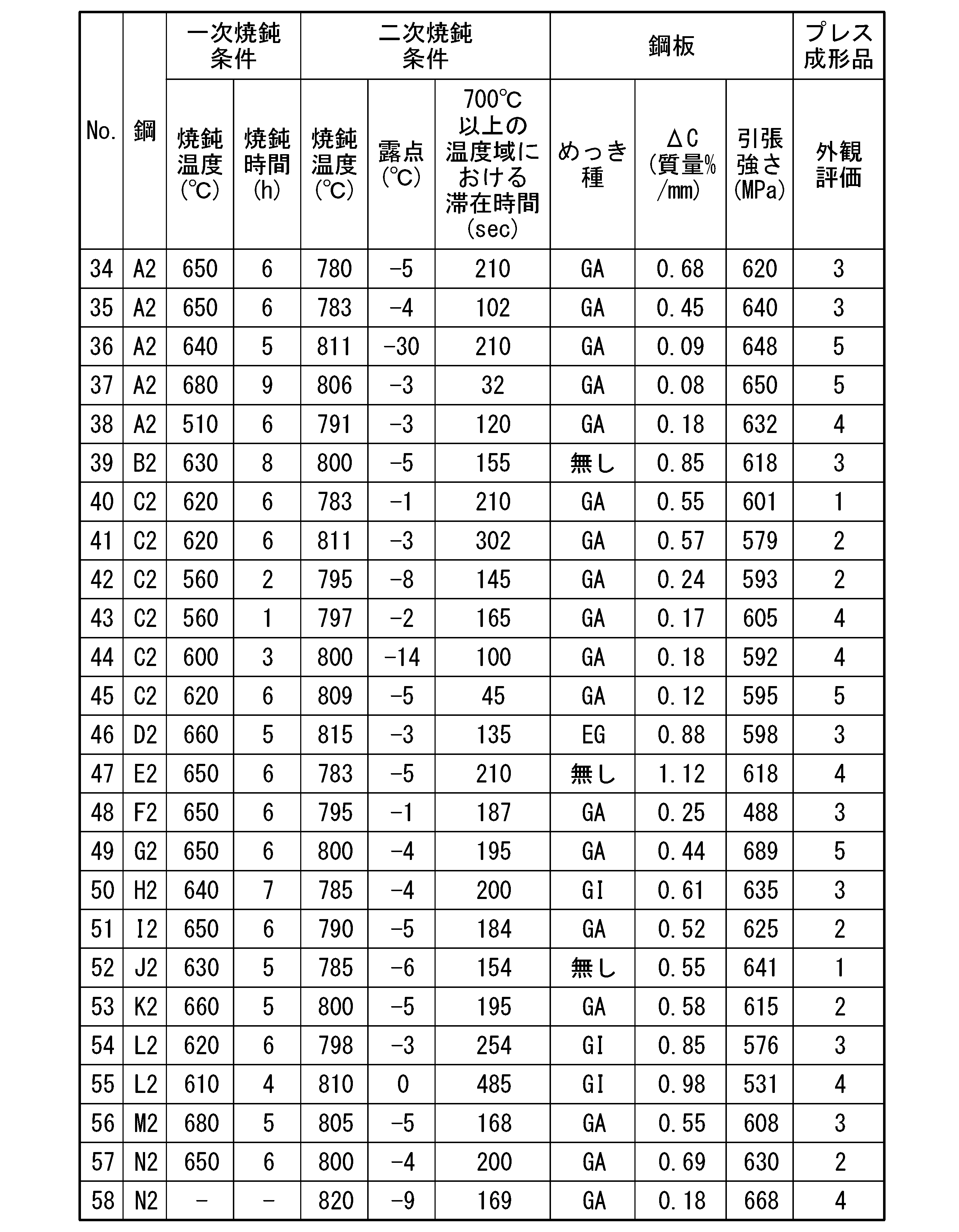
20 ブランキング装置
30 収容装置
Claims (10)
- 鋼板を備える自動車用外板部品であって、
平面視で、車体左右方向に沿って前記鋼板の圧延方向が延在している、自動車用外板部品。 - 到達降伏応力が400MPa以上である、請求項1に記載の自動車用外板部品。
- 前記鋼板の化学組成が、質量%で、
C :0.040~0.105%、
Mn:1.00~2.30%、
Si:0.005~1.500%、
Al:0.005~0.700%、
P :0.100%以下、
S :0.0200%以下、
N :0.0150%以下、
O :0.0100%以下、
Cr:0~0.80%、
Mo:0~0.16%、
B :0~0.0100%、
Ti:0~0.100%、
Nb:0~0.060%、
V :0~0.50%、
Ni:0~1.00%、
Cu:0~1.00%、
W :0~1.00%、
Sn:0~1.00%、
Sb:0~0.200%、
Ca:0~0.0100%、
Mg:0~0.0100%、
Zr:0~0.0100%、
REM:0~0.0100%、並びに
残部:Fe及び不純物である、請求項1又は2に記載の自動車用外板部品。 - 自動車用外板部品の素材であり、鋼板を備えるブランクシートであって、
前記鋼板の圧延方向が前記ブランクシートの長手方向に沿って延在し、
厚さが0.6mm以下である、ブランクシート。 - 前記鋼板の化学組成が、質量%で、
C :0.040~0.105%、
Mn:1.00~2.30%、
Si:0.005~1.500%、
Al:0.005~0.700%、
P :0.100%以下、
S :0.0200%以下、
N :0.0150%以下、
O :0.0100%以下、
Cr:0~0.80%、
Mo:0~0.16%、
B :0~0.0100%、
Ti:0~0.100%、
Nb:0~0.060%、
V :0~0.50%、
Ni:0~1.00%、
Cu:0~1.00%、
W :0~1.00%、
Sn:0~1.00%、
Sb:0~0.200%、
Ca:0~0.0100%、
Mg:0~0.0100%、
Zr:0~0.0100%、
REM:0~0.0100%、並びに
残部:Fe及び不純物である、請求項4に記載のブランクシート。 - 前記鋼板の化学組成が、質量%で、
C :0.040~0.100%、
Mn:1.00~2.00%、
Si:0.005~1.500%、
P :0.100%以下、
S :0.0200%以下、
Al:0.005~0.700%、
N :0.0150%以下、
O :0.0100%以下、
Cr:0~0.80%、
Mo:0~0.16%、
B :0~0.0100%、
Ti:0~0.100%、
Nb:0~0.060%、
V :0~0.50%、
Ni:0~1.00%、
Cu:0~1.00%、
W :0~1.00%、
Sn:0~1.00%、
Sb:0~0.200%、
Ca:0~0.0100%、
Mg:0~0.0100%、
Zr:0~0.0100%、
REM:0~0.0100%、及び
残部:Fe及び不純物であり、
算術平均うねりWaが0.10~0.30μmである、請求項4又は5に記載のブランクシート。 - 前記鋼板の化学組成が、質量%で、
C :0.040~0.105%、
Mn:1.00~2.30%、
Si:0.005~1.500%、
Al:0.005~0.700%、
P :0.100%以下、
S :0.0200%以下、
N :0.0150%以下、
O :0.0100%以下、
Cr:0~0.80%、
Mo:0~0.16%、
Ti:0~0.100%、
B :0~0.0100%、
Nb:0~0.060%、
V :0~0.50%、
Ni:0~1.00%、
Cu:0~1.00%、
W :0~1.00%、
Sn:0~1.00%、
Sb:0~0.200%、
Ca:0~0.0100%、
Mg:0~0.0100%、
Zr:0~0.0100%、
REM:0~0.0100%、並びに
残部:Fe及び不純物であり、
表面から20μm深さ位置のC含有量であるC20と、前記表面から60μm深さ位置のC含有量であるC60と、下記式(1)とから算出されるΔCが0.20~0.90質量%/mmであり、
引張強さが500MPa以上である、請求項4又は5に記載のブランクシート。
ΔC=(C60-C20)/(0.04) …(1) - 鋼板を備えるブランクシートの製造方法であって、
前記鋼板の圧延方向が前記ブランクシートの長手方向に沿って延在するように、前記鋼板をブランキングするブランキング工程を有する、ブランクシートの製造方法。 - ブランキング工程では、前記鋼板を互い違いにブランキングする、請求項8に記載のブランクシートの製造方法。
- 鋼板からブランクシートを切り出すシャー又は前記鋼板から前記ブランクシートを打ち抜く金型を有するブランキング装置を備え、
前記ブランキング装置は、前記鋼板の圧延方向が前記ブランクシートの長手方向に沿って延在するように、前記鋼板をブランキングする、ブランクシートの製造設備。
Priority Applications (5)
| Application Number | Priority Date | Filing Date | Title |
|---|---|---|---|
| EP21955079.5A EP4393795A4 (en) | 2021-08-27 | 2021-08-27 | EXTERNAL PANEL COMPONENT FOR AUTOMOBILE, BLANK SHEET METAL, BLANK SHEET METAL MANUFACTURING METHOD AND BLANK SHEET METAL MANUFACTURING EQUIPMENT |
| CN202180101724.3A CN117836195A (zh) | 2021-08-27 | 2021-08-27 | 汽车用外板部件、坯料片、坯料片的制造方法和坯料片的制造设备 |
| JP2023543608A JP7737031B2 (ja) | 2021-08-27 | 2021-08-27 | 自動車用外板部品、ブランクシート、ブランクシートの製造方法、及びブランクシートの製造設備 |
| PCT/JP2021/031495 WO2023026469A1 (ja) | 2021-08-27 | 2021-08-27 | 自動車用外板部品、ブランクシート、ブランクシートの製造方法、及びブランクシートの製造設備 |
| US18/579,354 US12522907B2 (en) | 2021-08-27 | 2021-08-27 | Outer plate component for automobile, blank sheet, manufacturing method for blank sheet, and manufacturing facility for blank sheet |
Applications Claiming Priority (1)
| Application Number | Priority Date | Filing Date | Title |
|---|---|---|---|
| PCT/JP2021/031495 WO2023026469A1 (ja) | 2021-08-27 | 2021-08-27 | 自動車用外板部品、ブランクシート、ブランクシートの製造方法、及びブランクシートの製造設備 |
Publications (1)
| Publication Number | Publication Date |
|---|---|
| WO2023026469A1 true WO2023026469A1 (ja) | 2023-03-02 |
Family
ID=85322576
Family Applications (1)
| Application Number | Title | Priority Date | Filing Date |
|---|---|---|---|
| PCT/JP2021/031495 Ceased WO2023026469A1 (ja) | 2021-08-27 | 2021-08-27 | 自動車用外板部品、ブランクシート、ブランクシートの製造方法、及びブランクシートの製造設備 |
Country Status (5)
| Country | Link |
|---|---|
| US (1) | US12522907B2 (ja) |
| EP (1) | EP4393795A4 (ja) |
| JP (1) | JP7737031B2 (ja) |
| CN (1) | CN117836195A (ja) |
| WO (1) | WO2023026469A1 (ja) |
Cited By (2)
| Publication number | Priority date | Publication date | Assignee | Title |
|---|---|---|---|---|
| WO2024203606A1 (ja) * | 2023-03-30 | 2024-10-03 | 株式会社神戸製鋼所 | 鋼板および鋼板の製造方法 |
| KR20260037160A (ko) | 2023-08-29 | 2026-03-17 | 닛폰세이테츠 가부시키가이샤 | 패널 |
Families Citing this family (2)
| Publication number | Priority date | Publication date | Assignee | Title |
|---|---|---|---|---|
| WO2022255497A1 (ja) * | 2021-06-04 | 2022-12-08 | 日本製鉄株式会社 | 自動車外装部品 |
| CN117616143A (zh) * | 2021-08-27 | 2024-02-27 | 日本制铁株式会社 | 钢板及压制成形品 |
Citations (4)
| Publication number | Priority date | Publication date | Assignee | Title |
|---|---|---|---|---|
| JPH0230306A (ja) | 1988-07-15 | 1990-01-31 | Sumitomo Metal Ind Ltd | 表面性状の優れた金属板とその製造に用いる圧延ロールおよびその製造方法 |
| WO1998055246A1 (fr) | 1997-06-05 | 1998-12-10 | Toyo Kohan Co., Ltd. | Recipient cylindrique revetu de resine et procede de fabrication |
| JP2003105512A (ja) * | 2001-09-26 | 2003-04-09 | Honda Motor Co Ltd | 車体パネル用亜鉛鋼板の製造方法 |
| JP2017002333A (ja) * | 2015-06-04 | 2017-01-05 | 新日鐵住金株式会社 | 形状凍結性に優れた高強度鋼板およびその製造方法 |
Family Cites Families (5)
| Publication number | Priority date | Publication date | Assignee | Title |
|---|---|---|---|---|
| JP3476495B2 (ja) * | 1992-03-31 | 2003-12-10 | Jfeスチール株式会社 | プレス加工用薄鋼板 |
| DE102012017703A1 (de) * | 2012-09-07 | 2014-03-13 | Daetwyler Graphics Ag | Flachprodukt aus Metallwerkstoff, insbesondere einem Stahlwerkstoff, Verwendung eines solchen Flachprodukts sowie Walze und Verfahren zur Herstellung solcher Flachprodukte |
| CN103586353B (zh) | 2013-11-25 | 2016-04-27 | 东风汽车公司 | 汽车左右翼子板冲压工艺及其拉延模具 |
| CN105063484B (zh) * | 2015-08-28 | 2017-10-31 | 宝山钢铁股份有限公司 | 屈服强度500MPa级高延伸率热镀铝锌及彩涂钢板及其制造方法 |
| CN106964722A (zh) | 2017-03-30 | 2017-07-21 | 柳州职业技术学院 | 一种汽车发动机盖外板的冲压工艺及装备 |
-
2021
- 2021-08-27 CN CN202180101724.3A patent/CN117836195A/zh active Pending
- 2021-08-27 JP JP2023543608A patent/JP7737031B2/ja active Active
- 2021-08-27 US US18/579,354 patent/US12522907B2/en active Active
- 2021-08-27 EP EP21955079.5A patent/EP4393795A4/en active Pending
- 2021-08-27 WO PCT/JP2021/031495 patent/WO2023026469A1/ja not_active Ceased
Patent Citations (4)
| Publication number | Priority date | Publication date | Assignee | Title |
|---|---|---|---|---|
| JPH0230306A (ja) | 1988-07-15 | 1990-01-31 | Sumitomo Metal Ind Ltd | 表面性状の優れた金属板とその製造に用いる圧延ロールおよびその製造方法 |
| WO1998055246A1 (fr) | 1997-06-05 | 1998-12-10 | Toyo Kohan Co., Ltd. | Recipient cylindrique revetu de resine et procede de fabrication |
| JP2003105512A (ja) * | 2001-09-26 | 2003-04-09 | Honda Motor Co Ltd | 車体パネル用亜鉛鋼板の製造方法 |
| JP2017002333A (ja) * | 2015-06-04 | 2017-01-05 | 新日鐵住金株式会社 | 形状凍結性に優れた高強度鋼板およびその製造方法 |
Non-Patent Citations (1)
| Title |
|---|
| See also references of EP4393795A4 |
Cited By (2)
| Publication number | Priority date | Publication date | Assignee | Title |
|---|---|---|---|---|
| WO2024203606A1 (ja) * | 2023-03-30 | 2024-10-03 | 株式会社神戸製鋼所 | 鋼板および鋼板の製造方法 |
| KR20260037160A (ko) | 2023-08-29 | 2026-03-17 | 닛폰세이테츠 가부시키가이샤 | 패널 |
Also Published As
| Publication number | Publication date |
|---|---|
| JPWO2023026469A1 (ja) | 2023-03-02 |
| EP4393795A1 (en) | 2024-07-03 |
| US20240352565A1 (en) | 2024-10-24 |
| EP4393795A4 (en) | 2024-10-16 |
| JP7737031B2 (ja) | 2025-09-10 |
| US12522907B2 (en) | 2026-01-13 |
| CN117836195A (zh) | 2024-04-05 |
Similar Documents
| Publication | Publication Date | Title |
|---|---|---|
| TWI589709B (zh) | 熔融鍍鋅鋼板 | |
| JP7737031B2 (ja) | 自動車用外板部品、ブランクシート、ブランクシートの製造方法、及びブランクシートの製造設備 | |
| TWI558820B (zh) | 熔融鍍鋅鋼板 | |
| WO2024122037A1 (ja) | 高強度鋼板、高強度鋼板を用いてなる部材、部材からなる自動車の骨格構造部品用又は自動車の補強部品、ならびに高強度鋼板及び部材の製造方法 | |
| WO2023218732A1 (ja) | 鋼板、部材およびそれらの製造方法 | |
| CN117062928A (zh) | 镀锌钢板、部件以及它们的制造方法 | |
| WO2023026819A1 (ja) | 高強度鋼板およびその製造方法 | |
| EP3693485A1 (en) | Hot-stamp molded article, hot-stamp steel sheet, and methods for producing these | |
| KR102888792B1 (ko) | 핫 스탬프용 강판 및 그 제조 방법, 그리고, 핫 스탬프 부재 및 그 제조 방법 | |
| WO2023218577A1 (ja) | 亜鉛めっき鋼板、部材およびそれらの製造方法 | |
| WO2023190867A1 (ja) | 鋼部材及び鋼板 | |
| KR20230137436A (ko) | 핫 스탬프용 강판 및 핫 스탬프 성형체 | |
| CN116997671A (zh) | 热冲压用钢板及热冲压成型体 | |
| CN118574944A (zh) | 热轧高强度钢带材 | |
| KR20240075861A (ko) | 핫 스탬프용 강판 및 핫 스탬프 성형체 | |
| JP2006291272A (ja) | 高強度冷延鋼板、溶融亜鉛めっき鋼板、それらの製造方法 | |
| JP7601256B2 (ja) | 鋼板、部材およびそれらの製造方法 | |
| JP7820407B2 (ja) | 鋼板、部材およびそれらの製造方法 | |
| WO2023199776A1 (ja) | ホットスタンプ成形体 | |
| JP7623618B2 (ja) | 鋼板およびプレス成形品 | |
| JP7473860B1 (ja) | 高強度鋼板、その製造方法、部材及び自動車部品 | |
| JP7740597B2 (ja) | 鋼板、部材およびそれらの製造方法 | |
| JP7709076B2 (ja) | 鋼板およびプレス成形品 | |
| WO2025263571A1 (ja) | 鋼部材及び鋼板 | |
| WO2025263572A1 (ja) | 鋼部材及び鋼板 |
Legal Events
| Date | Code | Title | Description |
|---|---|---|---|
| 121 | Ep: the epo has been informed by wipo that ep was designated in this application |
Ref document number: 21955079 Country of ref document: EP Kind code of ref document: A1 |
|
| WWE | Wipo information: entry into national phase |
Ref document number: 18579354 Country of ref document: US |
|
| WWE | Wipo information: entry into national phase |
Ref document number: 2023543608 Country of ref document: JP |
|
| WWE | Wipo information: entry into national phase |
Ref document number: 202417005241 Country of ref document: IN |
|
| WWE | Wipo information: entry into national phase |
Ref document number: 202180101724.3 Country of ref document: CN |
|
| WWE | Wipo information: entry into national phase |
Ref document number: 2021955079 Country of ref document: EP |
|
| NENP | Non-entry into the national phase |
Ref country code: DE |
|
| ENP | Entry into the national phase |
Ref document number: 2021955079 Country of ref document: EP Effective date: 20240327 |
|
| WWG | Wipo information: grant in national office |
Ref document number: 18579354 Country of ref document: US |