WO2023033106A1 - 押輪、管継手および管の接合方法 - Google Patents
押輪、管継手および管の接合方法 Download PDFInfo
- Publication number
- WO2023033106A1 WO2023033106A1 PCT/JP2022/032945 JP2022032945W WO2023033106A1 WO 2023033106 A1 WO2023033106 A1 WO 2023033106A1 JP 2022032945 W JP2022032945 W JP 2022032945W WO 2023033106 A1 WO2023033106 A1 WO 2023033106A1
- Authority
- WO
- WIPO (PCT)
- Prior art keywords
- socket
- ring
- push ring
- pipe
- reinforcing member
- Prior art date
- Legal status (The legal status is an assumption and is not a legal conclusion. Google has not performed a legal analysis and makes no representation as to the accuracy of the status listed.)
- Ceased
Links
Images


Classifications
-
- F—MECHANICAL ENGINEERING; LIGHTING; HEATING; WEAPONS; BLASTING
- F16—ENGINEERING ELEMENTS AND UNITS; GENERAL MEASURES FOR PRODUCING AND MAINTAINING EFFECTIVE FUNCTIONING OF MACHINES OR INSTALLATIONS; THERMAL INSULATION IN GENERAL
- F16L—PIPES; JOINTS OR FITTINGS FOR PIPES; SUPPORTS FOR PIPES, CABLES OR PROTECTIVE TUBING; MEANS FOR THERMAL INSULATION IN GENERAL
- F16L27/00—Adjustable joints; Joints allowing movement
- F16L27/10—Adjustable joints; Joints allowing movement comprising a flexible connection only
- F16L27/1017—Joints with sleeve or socket
-
- F—MECHANICAL ENGINEERING; LIGHTING; HEATING; WEAPONS; BLASTING
- F16—ENGINEERING ELEMENTS AND UNITS; GENERAL MEASURES FOR PRODUCING AND MAINTAINING EFFECTIVE FUNCTIONING OF MACHINES OR INSTALLATIONS; THERMAL INSULATION IN GENERAL
- F16L—PIPES; JOINTS OR FITTINGS FOR PIPES; SUPPORTS FOR PIPES, CABLES OR PROTECTIVE TUBING; MEANS FOR THERMAL INSULATION IN GENERAL
- F16L21/00—Joints with sleeve or socket
- F16L21/02—Joints with sleeve or socket with elastic sealing rings between pipe and sleeve or between pipe and socket, e.g. with rolling or other prefabricated profiled rings
- F16L21/04—Joints with sleeve or socket with elastic sealing rings between pipe and sleeve or between pipe and socket, e.g. with rolling or other prefabricated profiled rings in which sealing rings are compressed by axially-movable members
-
- F—MECHANICAL ENGINEERING; LIGHTING; HEATING; WEAPONS; BLASTING
- F16—ENGINEERING ELEMENTS AND UNITS; GENERAL MEASURES FOR PRODUCING AND MAINTAINING EFFECTIVE FUNCTIONING OF MACHINES OR INSTALLATIONS; THERMAL INSULATION IN GENERAL
- F16L—PIPES; JOINTS OR FITTINGS FOR PIPES; SUPPORTS FOR PIPES, CABLES OR PROTECTIVE TUBING; MEANS FOR THERMAL INSULATION IN GENERAL
- F16L21/00—Joints with sleeve or socket
- F16L21/08—Joints with sleeve or socket with additional locking means
-
- F—MECHANICAL ENGINEERING; LIGHTING; HEATING; WEAPONS; BLASTING
- F16—ENGINEERING ELEMENTS AND UNITS; GENERAL MEASURES FOR PRODUCING AND MAINTAINING EFFECTIVE FUNCTIONING OF MACHINES OR INSTALLATIONS; THERMAL INSULATION IN GENERAL
- F16L—PIPES; JOINTS OR FITTINGS FOR PIPES; SUPPORTS FOR PIPES, CABLES OR PROTECTIVE TUBING; MEANS FOR THERMAL INSULATION IN GENERAL
- F16L37/00—Couplings of the quick-acting type
- F16L37/08—Couplings of the quick-acting type in which the connection between abutting or axially overlapping ends is maintained by locking members
- F16L37/12—Couplings of the quick-acting type in which the connection between abutting or axially overlapping ends is maintained by locking members using hooks, pawls, or other movable or insertable locking members
- F16L37/14—Joints secured by inserting between mating surfaces an element, e.g. a piece of wire, a pin, a chain
Definitions
- the present invention relates to a push ring used in a pipe joint having a socket and a spigot, a pipe joint provided with the push ring, and a pipe joining method using the push ring.
- the insertion port 102 of the first pipe 101 is inserted into the socket 104 of the second pipe 103, for example, as shown in FIG.
- a seal member 105 is inserted between the outer periphery of the insertion port 102 and the inner periphery of the receptacle 104 .
- a push ring 106 is fitted over the insertion port 102 and faces the open end face 107 of the socket 104 from the outside. Push ring 106 is connected to socket 104 by a plurality of bolts 108 and nuts 109 .
- the press ring 106 includes an annular body portion 110, a pressing surface 111 that contacts the seal member 105 and presses the seal member 105, a plurality of protrusions 112 that contact the opening end surface 107 of the socket 104, and a bolt 108. It has a plurality of bolt insertion holes 113 to be inserted.
- the pressing surface 111 and the protrusion 112 are provided on one side of the pressing ring 106 (that is, the side facing the socket 104).
- the protrusion 112 abuts the opening end face 107 of the socket 104 to keep the distance from the pressing surface 111 to the opening end face 107 of the socket 104 at a predetermined distance.
- the intervals G between the bolt insertion holes 113 in the circumferential direction A of the pressing ring 106 are all kept equal.
- the bolt 108 is inserted through the bolt insertion hole 113 of the press ring 106, and the bolt 108 and the nut 109 are tightened.
- the pressing surface 111 of the press ring 106 comes into contact with the sealing member 105 and pushes the sealing member 105 between the outer periphery of the insertion port 102 and the inner periphery of the receiving port 104 .
- Japanese Patent Application Laid-Open No. 2014-5868 can be referred to for the press ring 106 and the pipe joint 100 as described above.
- the bolt 108 is inserted through the bolt insertion hole 113 positioned directly below the first pipe 101 because the gap H between the bolt insertion hole 113 positioned directly below the first pipe 101 and the bottom 115 of the groove 114 is narrow. It is difficult to perform the work of tightening the nut 109 by doing so. Therefore, the workability of joining the first pipe 101 and the second pipe 103 is low. As a countermeasure, it is necessary to secure a wide space H between the bolt insertion hole 113 located directly below the first pipe 101 and the bottom 115 of the groove 114, requiring a large work space.
- the first pipe 101 and the second pipe 103 are joined inside the groove 114 as described above, for example, the first pipe 101 and the second pipe 103 are joined along an obstacle such as a wall.
- the distance between the bolt insertion hole 113 located on the side where the obstacle exists and the obstacle is narrowed. For this reason, it is difficult to insert the bolt 108 into the bolt insertion hole 113 located on the side where the obstacle exists and to tighten the nut 109, resulting in low workability when joining the pipes 101 and 103. Therefore, it is necessary to secure a wide space between the bolt insertion hole 113 located on the side where the obstacle exists and the obstacle, requiring a large working space.
- An object of the present invention is to provide a press ring, a pipe joint, and a method for joining pipes, which have good workability when joining pipes even if the work space between the press ring and an obstacle is narrow.
- the insertion opening is inserted into the socket
- a seal member is provided in the pipe joint inserted between the outer circumference of the spigot and the inner circumference of the socket
- a pressing surface that presses the seal member, a plurality of fastener insertion holes through which the fasteners are inserted, an evenly spaced region in which the intervals between the fastener insertion holes in the circumferential direction are kept at equal intervals, and an enlarged spacing region in which the spacing between any two adjacent fastener insertion holes is greater than the uniform spacing; It is characterized in that a reinforcing member is provided in the enlarged spacing region.
- the insertion opening is inserted into the socket, and the fastener is tightened with the enlarged space area of the press ring facing the obstacle. Insert it into the tool insertion hole and tighten it.
- the push ring is connected to the socket and the seal member is inserted between the outer circumference of the socket and the inner circumference of the socket.
- the fastener insertion holes in the enlarged gap area are more likely to be inserted around the circumference of the push ring than the position closest to the obstacle. It exists in the position distributed to the direction. As a result, the gap between the fastener insertion hole and the obstacle in the enlarged gap area is large, so even if the work space between the push ring and the obstacle is narrow, the workability when joining the pipes is good. can be
- the reinforcing member maintains sufficient rigidity in the enlarged spacing region of the pressing ring, even if the reaction force of the sealing member acts on the pressing ring, it is possible to prevent the enlarged spacing region of the pressing ring from bending due to the reaction force. .
- the expanded space area faces an obstacle that hinders the joining work of joining the pipes.
- the reinforcing member is provided on the surface opposite to the pressing surface, and protrudes from the surface opposite to the pressing surface in the direction in which the insertion opening separates from the socket. and is located radially outside the inner circumference of the push ring, A stepped portion is preferably formed between the inner circumference of the pressing ring and the inner circumference of the reinforcing member.
- the first pipe may be pushed into the second pipe by an earthquake or the like.
- the bending angle until the first tube contacts the reinforcing member of the push ring is compared to the bending angle when the inner circumference of the reinforcing member is at the same position as the inner circumference of the pushing ring in the radial direction. , increases. This reduces the load on the push ring when the first tube is bent with respect to the second tube.
- the fasteners When inserting a plurality of fasteners into a plurality of fastener insertion holes and connecting the push ring to the socket, the fasteners are unevenly tightened to reinforce the push ring even if the push ring is inclined with respect to the first pipe.
- the angle of inclination until the member contacts the first tube is increased compared to the angle of inclination if the inner circumference of the reinforcing member were radially at the same position as the inner circumference of the push ring.
- the reinforcing member is provided on the surface opposite to the pressing surface, and protrudes from the surface opposite to the pressing surface in the direction in which the insertion opening separates from the socket. and is located radially outside the inner circumference of the push ring, A tapered portion is formed between the inner periphery of the pressing ring and the inner periphery of the reinforcing member, It is preferable that the tapered portion is inclined outward in the radial direction in the direction in which the insertion port is separated from the receptacle.
- the first pipe may be pushed into the second pipe by an earthquake or the like.
- the bending angle until the first tube contacts the reinforcing member of the push ring is compared to the bending angle when the inner circumference of the reinforcing member is at the same position as the inner circumference of the pushing ring in the radial direction. , increases. This reduces the load on the push ring when the first tube is bent with respect to the second tube.
- the fasteners are unevenly tightened so that even if the push ring is tilted with respect to the first pipe, the push ring can still be secured.
- the inclination angle until the reinforcing member contacts the first tube increases compared to the inclination angle when the inner circumference of the reinforcing member is radially at the same position as the inner circumference of the push ring.
- the reinforcing member is preferably provided between two adjacent fastener insertion holes in the enlarged interval region.
- the pipe joint provided with the above-described push ring of the present invention is The spigot is inserted into the socket, a sealing member is inserted between the outer periphery of the receptacle and the inner periphery of the receptacle;
- the press ring is fitted over the insertion opening and faces the opening end face of the socket from the outside, and is received by a plurality of fasteners in a state in which the enlarged space area faces an obstacle that hinders the joining operation of the pipes.
- the pressing surface of the press ring abuts against the seal member, The fastener is inserted through the fastener insertion hole of the push ring.
- the method for joining pipes using the pressing ring of the present invention includes: The insert is inserted into the socket, and the fastener is inserted through the fastener insertion hole of the push ring and tightened in a state in which the expanded gap region of the push ring faces an obstacle that interferes with the joining operation of the pipes.
- the press ring is connected to the socket, and the sealing member is inserted between the outer circumference of the insertion opening and the inner circumference of the socket.
- the insertion opening is inserted into the socket, and the fastener is inserted through the fastener insertion hole of the press ring in a state in which the insertion opening is obliquely bent with respect to the socket.
- the push ring is preferably connected to the socket by tightening.
- the reinforcing member maintains sufficient rigidity in the enlarged interval region of the push ring, even if the reaction force of the seal member acts on the push ring, the enlarged interval region of the push ring is prevented from bending due to the reaction force. can be done.
- FIG. 4 is a cross-sectional view taken along the line XX in FIG. 3;
- FIG. 4 is a cross-sectional view taken along line YY in FIG. 3;
- FIG. 4 is a ZZ cross-sectional view in FIG. 3;
- It is a perspective view of the front side of the push ring of the same pipe joint. It is a perspective view of the back side of the press ring of the same pipe joint.
- FIG. 4 is a schematic diagram showing a joining operation of joining pipes together using a pipe joint inside a groove formed in the ground.
- FIG. 4 is a cross-sectional view of the same pipe joint, showing how the first pipe is bent with respect to the second pipe after joining the pipes.
- 12 is an enlarged view of a part of the cross-sectional view of the pipe joint in FIG. 11;
- FIG. 4 is a cross-sectional view of the same pipe joint, showing a state in which, when joining pipes, uneven tightening is performed to connect the press ring to the socket.
- 14 is an enlarged view of a part of the cross-sectional view of the pipe joint in FIG. 13;
- FIG. It is a sectional view of a pipe joint in a 2nd embodiment of the present invention.
- FIG. 4 is a schematic diagram showing a joining operation of joining pipes together using a pipe joint inside a groove formed in the ground.
- FIG. 4 is a cross-sectional view of the same pipe joint, showing how the first pipe
- FIG. 11 is a schematic diagram showing how pipes are joined together using a pipe joint for rising pipes laid vertically along the wall of a building in the third embodiment of the present invention.
- FIG. 11 is a cross-sectional view showing a pipe joining method according to a fourth embodiment of the present invention, showing how the press ring is connected to the socket while the insertion socket is bent with respect to the socket.
- 18 is an enlarged view of a part of the cross-sectional view in FIG. 17;
- FIG. FIG. 10 is a cross-sectional view of a conventional pipe joint provided with a push ring; It is a front view of the same push ring.
- FIG. 4 is a schematic diagram showing how pipes are joined together using a conventional pipe joint inside a groove formed in the ground.
- a pipe joint 1 joins a first pipe 2 and a second pipe 4, both made of cast iron.
- a receptacle 3 provided at the end of the first tube 2 is inserted into a socket 5 provided at the end of the second tube 4 .
- a ring-shaped rubber ring 7 (an example of a sealing member) is inserted between the outer periphery of the insertion port 3 and the inner periphery of the socket 5 .
- a lock ring groove 9 is formed on the inner circumference of the socket 5 and further inside the socket 5 than the rubber ring 7 over the entire circumference.
- the lock ring groove 9 is equipped with a lock ring 10 that is split in the circumferential direction.
- the insertion port 3 has a protruding portion 11 that can be engaged with the lock ring 10 from the depth of the socket 5 on the outer periphery of the tip portion over the entire circumference.
- a circumferentially split backup ring 13 is fitted on the insertion opening 3 and is adjacent to the lock ring 10 .
- the socket 5 has a flange portion 5a at its tip.
- a plurality of bolt holes 12 are formed in the flange portion 5a.
- eight bolt holes 12 are formed in the flange portion 5a.
- the first pipe 2 and the second pipe 4 are laid horizontally, and any two bolt holes 12 are positioned on the vertical line.
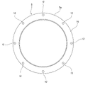
- a push ring 14 for pushing the rubber ring 7 deep into the socket 5 is fitted on the insertion slot 3 and faces the open end face 15 of the socket 5 from the outside.
- the push ring 14 has an annular main body 14a and is connected to the receptacle 5 by a plurality (for example, seven) of T-head bolts 16 (an example of a fastener) and nuts 17 (an example of a fastener).
- the main body 14a has a plurality of protrusions 14b protruding radially outward on its outer periphery.
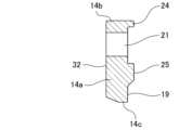
- the main body 14a includes a pressing surface 19 for pressing the rubber ring 7, a plurality of bolt insertion holes 21 (an example of fastener insertion holes) through which the T-head bolts 16 are inserted, a reinforcing member 23, and a first projection. 24 and a second protrusion 25 are provided.
- a projecting portion 14 b of the main body 14 a is formed to correspond to the bolt insertion hole 21 .
- the push ring 14 has an evenly spaced region 29 and an enlarged spaced region 30 .
- the interval between the bolt insertion holes 21 in the circumferential direction A is maintained at an even interval S1.
- the interval S2 between any two adjacent bolt insertion holes 21 is larger than the uniform interval S1.
- each bolt insertion hole 21 in the equally spaced region 29 is 45°.
- a distribution angle B2 of both bolt insertion holes 21 in the enlarged interval region 30 is 90°.
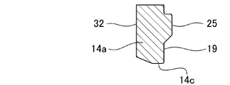
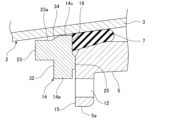
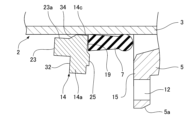
- the reinforcing member 23 is an arc-shaped member provided on the surface 32 opposite to the pressing surface 19, and protrudes from this surface 32 in the detachment direction C.
- the detachment direction C is the direction in which the insertion port 3 is detached from the receptacle 5 .
- the reinforcing member 23 is provided between two adjacent bolt insertion holes 21 in the enlarged interval region 30 .
- the reinforcing member 23 is located outside the inner circumference 14c of the push ring 14 in the radial direction D. As shown in FIG.
- a tapered portion 34 is formed over the entire length of the reinforcing member 23 between the inner circumference 14c of the push ring 14 and the inner circumference 23a of the reinforcing member 23. As shown in FIG. The tapered portion 34 is inclined outward in the radial direction D in the detachment direction C in which the insertion port 3 is detached from the receptacle 5 .
- both end portions 23b of the reinforcing member 23 are formed by two straight lines in the radial direction connecting the center of the push ring 14 and the centers of the bolt insertion holes 21 in the enlarged space area 30 from within the enlarged space area 30. 36 and enters the evenly spaced region 29 .
- the first convex portion 24 and the second convex portion 25 are in contact with the opening end face 15 of the socket 5 respectively.
- a plurality of first convex portions 24 are provided, and are positioned outside the bolt insertion holes 21 in the radial direction D of the push ring 14 .
- the second protrusion 25 is located inside the pressing ring 14 in the radial direction D of each bolt insertion hole 21 and is formed in an annular shape so as to surround the pressing surface 19 .
- the end of the rubber ring 7 is fitted inside the second protrusion 25 of the pressing ring 14 and comes into contact with the pressing surface 19 .
- the push ring 14 is connected to the socket 5 such that the enlarged spacing region 30 is located directly below the first tube 2 .
- the first pipe 2 and the second pipe 4 are joined inside a groove 39 formed by excavating the ground 38, with the bottom 40 of the groove 39 joining the first pipe. 2 and the second pipe 4 are obstructed. That is, the push ring 14 is connected to the receptacle 5 by a plurality of T-head bolts 16 and nuts 17 with the enlarged spacing region 30 facing the bottom 40 (an example of an obstacle) of the groove 39 .
- a method of joining the first tube 2 and the second tube 4 using the pressing ring 14 will be described below.
- the push ring 14 , the rubber ring 7 and the backup ring 13 are fitted onto the insertion opening 3 of the first tube 2 .
- the lock ring 10 is attached to the lock ring groove 9 of the socket 5 of the second pipe 4 already arranged inside the groove 39, and the lock ring 10 is expanded using an expander (not shown). keep the diameter
- the spigot 3 of the first tube 2 is inserted into the socket 5 of the second tube 4 inside the groove 39 .
- the projection 11 of the insertion opening 3 passes through the inner periphery of the lock ring 10 to the depth of the socket 5 .
- the lock ring 10 is reduced in diameter and clings to the outer circumference of the insertion opening 3 .
- the backup ring 13 is moved in the tube axis direction E and inserted into the socket 5 to be adjacent to the lock ring 10 . Further, the rubber ring 7 is moved in the tube axis direction E to be positioned in front of the opening end face 15 of the socket 5 .
- the T-head bolt 16 is inserted into the bolt hole 12 of the socket 5 and the bolt insertion hole of the press ring 14 . 21. Then, the nut 17 is screwed onto the T-head bolt 16 , and the nut 17 is tightened until the first projection 24 and the second projection 25 of the press ring 14 come into contact with the opening end face 15 of the socket 5 .
- the pressing ring 14 is connected to the socket 5, and the pressing surface 19 of the pressing ring 14 presses the rubber ring 7, so that the outer periphery of the insertion slot 3 and the inner periphery of the socket 5 are separated. Inserted between, the first tube 2 is joined to the second tube 4 .
- the bolt insertion holes 21 of the interval region 30 do not exist directly under the first pipe 2 , but exist at positions distributed in the circumferential direction A of the press ring 14 from directly under the first pipe 2 .
- the space H between the bolt insertion hole 21 of the enlarged space region 30 and the bottom 40 of the groove 39 becomes large, so even if the working space between the press ring 14 and the bottom 40 of the groove 39 is narrow, the first workability when joining the pipe 2 and the second pipe 4 can be improved.
- the enlarged spacing region 30 of the pressing ring 14 is kept sufficiently rigid by the reinforcing member 23, even if the reaction force of the rubber ring 7 acts on the pressing ring 14, the enlarged spacing region 30 of the pressing ring 14 bends due to the reaction force. can be prevented. Furthermore, since the reinforcing member 23 is provided, when the T-head bolt 16 is inserted into the bolt insertion hole 21 of the enlarged interval region 30 of the push ring 14 and the bolt hole 12 of the socket 5 and tightened with the nut 17, Even if a large load is generated between the two bolt insertion holes 21 in the enlarged space area 30, the enlarged space area 30 can be prevented from being deformed or damaged.
- the reinforcing member 23 is located outside the inner circumference 14c of the pressing ring 14 in the radial direction D, and a tapered portion is formed between the inner circumference 14c of the pressing ring 14 and the inner circumference 23a of the reinforcing member 23.
- 34 is formed, after the first pipe 2 and the second pipe 4 are joined as described above, as shown in FIGS.
- the bending angle ⁇ until the first tube 2 contacts the reinforcing member 23 of the push ring 14 is such that the inner circumference 23a of the reinforcing member 23 is the inner circumference 14c of the pushing ring 14 in the radial direction D. increases compared to the flexion angle when in the same position as . This reduces the load applied to the push ring 14 when the first tube 2 is bent with respect to the second tube 4 .
- the T-head bolt 16 is inserted through the bolt hole 12 of the socket 5 and the bolt insertion hole 21 of the push ring 14 to receive the push ring 14.
- the uppermost T-head bolt 16 and nut 17 are first tightened, and then the lower T-head bolt 16 and nut 17 are sequentially tightened. So-called "unilateral tightening” may be performed. In this way, by unevenly tightening the T-head bolt 16 and the nut 17, the reinforcing member 23 of the pressing ring 14 is in contact with the first tube 2 even if the pressing ring 14 is inclined with respect to the first tube 2.
- the reinforcing member 23 is located outside the inner circumference 14c of the push ring 14 in the radial direction D.
- a stepped portion 50 is formed over the entire length of the reinforcing member 23 between the inner circumference 14c of the push ring 14 and the inner circumference 23a of the reinforcing member 23 .
- the stepped portion 50 has a stepped surface parallel to the radial direction D. As shown in FIG.
- the first pipe 2 may move against the second pipe 4 due to an earthquake or the like.
- the bending angle ⁇ (see FIG. 11) at which the first tube 2 contacts the reinforcing member 23 of the push ring 14 when bent is such that the inner circumference 23a of the reinforcing member 23 is the same as the inner circumference 14c of the pushing ring 14 in the radial direction D. It increases compared to the flexion angle when in the same position.
- the T-head bolt 16 is inserted through the bolt hole 12 of the socket 5 and the bolt insertion hole 21 of the pressing ring 14, and the pressing ring 14 is attached to the socket 5.
- the reinforcing member 23 of the push ring 14 contacts the first pipe 2 even if the push ring 14 is inclined with respect to the first pipe 2.
- the inclination angle ⁇ (see FIG. 13) until the inner circumference 23a of the reinforcing member 23 is at the same position as the inner circumference 14c of the push ring 14 in the radial direction D is increased compared to the inclination angle ⁇ .
- the bottom 40 of the groove 39 is an obstacle that interferes with the work of joining the first pipe 2 and the second pipe 4 together.
- the push ring 14 is connected to the receptacle 5 by a plurality of T-head bolts 16 and nuts 17 with the enlarged spacing region 30 facing the bottom 40 of the groove 39 .
- the obstruction is not limited to the bottom 40 of groove 39 .
- the first pipe 2 and the second pipe 4 are, for example, rising pipes laid in the vertical direction. It is surrounded by walls 55-57 of the building. In such a case, the wall 55 closest to the first pipe 2 and the second pipe 4 becomes an obstacle that hinders the work of joining the first pipe 2 and the second pipe 4 .
- the push ring 14 is connected to the receptacle 5 by a plurality of T-head bolts 16 and nuts 17 with the enlarged spacing region 30 facing the wall 55 .
- the insertion port 3 is aligned with the socket 5 by inserting the T-head bolt 16 through the bolt hole 12 of the socket 5 and the bolt insertion hole 21 of the push ring 14 and tightening the nut 17, the push ring 14 is connected to the socket 5 in a straight state.
- the joining method is not limited to such a joining method.
- the insertion port 3 is obliquely bent with respect to the socket 5. In this state, the push ring 14 may be connected to the socket 5 by inserting the T-head bolt 16 through the bolt hole 12 of the socket 5 and the bolt insertion hole 21 of the push ring 14 and tightening the nut 17 .
- the push ring 14 having the tapered portion 34 is used. good too.
- both end portions 23b of the reinforcing member 23 enter the equal spacing region 29 from the enlarged spacing region 30 beyond the two straight lines 36.
- both ends 23 b of the reinforcing member 23 may be formed between the two straight lines 36 without crossing over the two straight lines 36 .
- the pressing ring 14 is formed with the tapered portion 34 as shown in FIG. 1, and in the second embodiment, the pressing ring 14 is formed with the stepped portion 50 as shown in FIG.
- the inner circumference 14c of the push ring 14 and the inner circumference 23a of the reinforcing member 23 are made to have the same diameter, and the inner circumference 14c of the pushing ring 14 and the reinforcing member 23 have the same diameter. It may be flush with the inner periphery 23a.
- the tapered portion 34 or the stepped portion 50 is formed as described above, the bending angle ⁇ (see FIG. 11) and the inclination angle ⁇ of the push ring 14 (see FIG. 13).
Landscapes
- Engineering & Computer Science (AREA)
- General Engineering & Computer Science (AREA)
- Mechanical Engineering (AREA)
- Joints With Sleeves (AREA)
- Mutual Connection Of Rods And Tubes (AREA)
Abstract
Description
上記のような押輪106および管継手100については日本国の特開2014-5868号公報を参照することができる。
シール部材が挿し口の外周と受口の内周との間に挿入される管継手に備えられ、
挿し口に外嵌されて受口の開口端面に外側から対向し且つ複数本の締結具により受口に連結されてシール部材を受口の奥へ押し込む押輪であって、
シール部材を押圧する押圧面と、締結具が挿通される複数の締結具挿通孔と、周方向における締結具挿通孔間の間隔が均等な間隔に保たれている均等間隔領域と、周方向において隣り合ういずれか2個の締結具挿通孔間の間隔が上記均等な間隔よりも拡大している拡大間隔領域とを有し、
拡大間隔領域に補強部材が設けられていることを特徴とする。
押輪の内周と補強部材の内周との間に段差部が形成されていることが好ましい。
押輪の内周と補強部材の内周との間にテーパー部が形成されており、
テーパー部は、挿し口が受口から離脱する離脱方向ほど径方向における外側へ傾斜していることが好ましい。
挿し口が受口に挿入され、
シール部材が挿し口の外周と受口の内周との間に挿入され、
押輪は、挿し口に外嵌されて受口の開口端面に外側から対向し、且つ、拡大間隔領域が管の接合作業の妨げになる障害物に対向した状態で、複数本の締結具によって受口に連結され、
押輪の押圧面がシール部材に当接し、
締結具が押輪の締結具挿通孔に挿通されていることを特徴とする。
挿し口を受口に挿入し、押輪の拡大間隔領域を管の接合作業の妨げになる障害物に対向させた状態で、締結具を押輪の締結具挿通孔に挿通して締め込むことにより、押輪を受口に連結するとともにシール部材を挿し口の外周と受口の内周との間に挿入することを特徴とする。
(第1の実施の形態)
挿し口3は、その先端部外周に、受口5の奥からロックリング10に係合可能な突部11を全周にわたり有している。
挿し口3には、周方向一つ割りのバックアップリング13が外嵌されてロックリング10に隣接している。
以下に、押輪14を用いた第1の管2と第2の管4との接合方法を説明する。
その後、拡径器(図示省略)を取り外すことにより、ロックリング10が縮径して挿し口3の外周に抱き付く。
(第2の実施の形態)
(第3の実施の形態)
(第4の実施の形態)
Claims (8)
- 挿し口が受口に挿入され、
シール部材が挿し口の外周と受口の内周との間に挿入される管継手に備えられ、
挿し口に外嵌されて受口の開口端面に外側から対向し且つ複数本の締結具により受口に連結されてシール部材を受口の奥へ押し込む押輪であって、
シール部材を押圧する押圧面と、締結具が挿通される複数の締結具挿通孔と、周方向における締結具挿通孔間の間隔が均等な間隔に保たれている均等間隔領域と、周方向において隣り合ういずれか2個の締結具挿通孔間の間隔が上記均等な間隔よりも拡大している拡大間隔領域とを有し、
拡大間隔領域に補強部材が設けられていることを特徴とする押輪。 - 拡大間隔領域が管同士を接合する接合作業の妨げになる障害物に対向することを特徴とする請求項1に記載の押輪。
- 補強部材は、押圧面とは反対側の面に設けられ、且つ、押圧面とは反対側の面よりも挿し口が受口から離脱する離脱方向へ突出しているとともに、押輪の内周よりも径方向における外側に位置しており、
押輪の内周と補強部材の内周との間に段差部が形成されていることを特徴とする請求項1又は請求項2に記載の押輪。 - 補強部材は、押圧面とは反対側の面に設けられ、且つ、押圧面とは反対側の面よりも挿し口が受口から離脱する離脱方向へ突出しているとともに、押輪の内周よりも径方向における外側に位置しており、
押輪の内周と補強部材の内周との間にテーパー部が形成されており、
テーパー部は、挿し口が受口から離脱する離脱方向ほど径方向における外側へ傾斜していることを特徴とする請求項1又は請求項2に記載の押輪。 - 補強部材は、拡大間隔領域において隣り合う2個の締結具挿通孔間に設けられていることを特徴とする請求項1に記載の押輪。
- 上記請求項1に記載の押輪を備えた管継手であって、
挿し口が受口に挿入され、
シール部材が挿し口の外周と受口の内周との間に挿入され、
押輪は、挿し口に外嵌されて受口の開口端面に外側から対向し、且つ、拡大間隔領域が管の接合作業の妨げになる障害物に対向した状態で、複数本の締結具によって受口に連結され、
押輪の押圧面がシール部材に当接し、
締結具が押輪の締結具挿通孔に挿通されていることを特徴とする管継手。 - 上記請求項1に記載の押輪を用いた管の接合方法であって、
挿し口を受口に挿入し、押輪の拡大間隔領域を管の接合作業の妨げになる障害物に対向させた状態で、締結具を押輪の締結具挿通孔に挿通して締め込むことにより、押輪を受口に連結するとともにシール部材を挿し口の外周と受口の内周との間に挿入することを特徴とする管の接合方法。 - 挿し口を受口に挿入して、挿し口を受口に対して斜めに屈曲させた状態で、締結具を押輪の締結具挿通孔に挿通して締め込むことにより、押輪を受口に連結することを特徴とする請求項7に記載の管の接合方法。
Priority Applications (4)
| Application Number | Priority Date | Filing Date | Title |
|---|---|---|---|
| US18/688,175 US20250180146A1 (en) | 2021-09-03 | 2022-09-01 | Gland, pipe joint, and method for joining pipes |
| CN202280070448.3A CN118234988A (zh) | 2021-09-03 | 2022-09-01 | 压环、管接头以及管的接合方法 |
| EP22864688.1A EP4382792A4 (en) | 2021-09-03 | 2022-09-01 | THRUST RING, PIPE FITTING AND METHOD OF CONNECTING PIPE |
| CA3230095A CA3230095A1 (en) | 2021-09-03 | 2022-09-01 | Gland, pipe joint, and method for joining pipes |
Applications Claiming Priority (2)
| Application Number | Priority Date | Filing Date | Title |
|---|---|---|---|
| JP2021143577A JP7649720B2 (ja) | 2021-09-03 | 2021-09-03 | 押輪、管継手および管の接合方法 |
| JP2021-143577 | 2021-09-03 |
Publications (1)
| Publication Number | Publication Date |
|---|---|
| WO2023033106A1 true WO2023033106A1 (ja) | 2023-03-09 |
Family
ID=85412361
Family Applications (1)
| Application Number | Title | Priority Date | Filing Date |
|---|---|---|---|
| PCT/JP2022/032945 Ceased WO2023033106A1 (ja) | 2021-09-03 | 2022-09-01 | 押輪、管継手および管の接合方法 |
Country Status (7)
| Country | Link |
|---|---|
| US (1) | US20250180146A1 (ja) |
| EP (1) | EP4382792A4 (ja) |
| JP (1) | JP7649720B2 (ja) |
| CN (1) | CN118234988A (ja) |
| CA (1) | CA3230095A1 (ja) |
| TW (1) | TW202319672A (ja) |
| WO (1) | WO2023033106A1 (ja) |
Families Citing this family (1)
| Publication number | Priority date | Publication date | Assignee | Title |
|---|---|---|---|---|
| USD1108590S1 (en) * | 2023-09-06 | 2026-01-06 | Advanced Drainage Systems, Inc. | Reducing flat top drainage structure |
Citations (7)
| Publication number | Priority date | Publication date | Assignee | Title |
|---|---|---|---|---|
| JPS5453318A (en) * | 1977-10-04 | 1979-04-26 | Kubota Ltd | Escape-out preventing device for pipe joint |
| JPS55107178A (en) * | 1978-11-13 | 1980-08-16 | Pont A Mousson | Pipe joint |
| JPH10122456A (ja) * | 1996-10-24 | 1998-05-15 | Kubota Corp | 管継手の耐震構造 |
| JP2001248758A (ja) * | 2000-03-03 | 2001-09-14 | Kurimoto Ltd | さや管内挿入工法用台車 |
| JP2003202093A (ja) * | 2001-10-30 | 2003-07-18 | Kubota Corp | 鞘管推進工法における耐震管継手 |
| JP2010286110A (ja) * | 2009-05-13 | 2010-12-24 | Kubota Corp | 管継手 |
| JP2014005868A (ja) | 2012-06-25 | 2014-01-16 | Kubota Corp | 押輪および継手および弁 |
Family Cites Families (15)
| Publication number | Priority date | Publication date | Assignee | Title |
|---|---|---|---|---|
| US689624A (en) * | 1901-02-06 | 1901-12-24 | Ella M Cozens | Pipe-joint. |
| US940098A (en) * | 1908-02-29 | 1909-11-16 | Nat Water Main Cleaning Co | Device for joining parts of conduits. |
| US2105022A (en) * | 1934-02-09 | 1938-01-11 | Stanton Ironworks Co Ltd | Pipe joint |
| US2108848A (en) * | 1934-06-30 | 1938-02-22 | Inner Tite Clamp Corp | Pipe joint |
| US2679410A (en) * | 1950-10-07 | 1954-05-25 | Southern Pipe & Casing Co | Bell and spigot joint and sealing clamp |
| US3469852A (en) * | 1965-10-23 | 1969-09-30 | Smith Blair Inc | Leak clamp for bell and spigot pipe joint |
| US3473573A (en) * | 1966-10-06 | 1969-10-21 | Baker Mfg Co | Well cap and seal therefor |
| US4411312A (en) * | 1980-08-26 | 1983-10-25 | Hewing Manufacturing Corporation | Water-tight conduit well cap |
| US5129681A (en) * | 1990-11-30 | 1992-07-14 | Yano Giken Co., Ltd. | Method of rendering laid pipeline flexible and pipe joint suited for executing this method |
| FR2714143B1 (fr) * | 1993-12-22 | 1996-03-15 | Gerard Chevrier | Dispositif de raccordement pour tuyaux et tubes hautes pressions. |
| GB2377737B (en) * | 2001-07-18 | 2004-02-25 | Saint Gobain Pipelines Plc | Improvements in or relating to pipe couplings |
| KR20100094048A (ko) * | 2009-02-18 | 2010-08-26 | (주) 삼정디씨피 | 플랜지 타입 메카니컬 조인트 |
| MY176920A (en) * | 2012-06-25 | 2020-08-26 | Kubota Kk | Sealing material, pressing ring, joint, and valve |
| GB201312284D0 (en) * | 2013-07-09 | 2013-08-21 | Crane Ltd | Pipe connection |
| US20250224054A1 (en) * | 2021-09-03 | 2025-07-10 | Kubota Corporation | Gland, pipe joint, and method for joining pipes |
-
2021
- 2021-09-03 JP JP2021143577A patent/JP7649720B2/ja active Active
-
2022
- 2022-09-01 WO PCT/JP2022/032945 patent/WO2023033106A1/ja not_active Ceased
- 2022-09-01 EP EP22864688.1A patent/EP4382792A4/en active Pending
- 2022-09-01 TW TW111133210A patent/TW202319672A/zh unknown
- 2022-09-01 CA CA3230095A patent/CA3230095A1/en active Pending
- 2022-09-01 CN CN202280070448.3A patent/CN118234988A/zh active Pending
- 2022-09-01 US US18/688,175 patent/US20250180146A1/en active Pending
Patent Citations (7)
| Publication number | Priority date | Publication date | Assignee | Title |
|---|---|---|---|---|
| JPS5453318A (en) * | 1977-10-04 | 1979-04-26 | Kubota Ltd | Escape-out preventing device for pipe joint |
| JPS55107178A (en) * | 1978-11-13 | 1980-08-16 | Pont A Mousson | Pipe joint |
| JPH10122456A (ja) * | 1996-10-24 | 1998-05-15 | Kubota Corp | 管継手の耐震構造 |
| JP2001248758A (ja) * | 2000-03-03 | 2001-09-14 | Kurimoto Ltd | さや管内挿入工法用台車 |
| JP2003202093A (ja) * | 2001-10-30 | 2003-07-18 | Kubota Corp | 鞘管推進工法における耐震管継手 |
| JP2010286110A (ja) * | 2009-05-13 | 2010-12-24 | Kubota Corp | 管継手 |
| JP2014005868A (ja) | 2012-06-25 | 2014-01-16 | Kubota Corp | 押輪および継手および弁 |
Non-Patent Citations (1)
| Title |
|---|
| See also references of EP4382792A4 |
Also Published As
| Publication number | Publication date |
|---|---|
| EP4382792A1 (en) | 2024-06-12 |
| JP7649720B2 (ja) | 2025-03-21 |
| CN118234988A (zh) | 2024-06-21 |
| CA3230095A1 (en) | 2023-03-09 |
| EP4382792A4 (en) | 2025-04-30 |
| JP2023037051A (ja) | 2023-03-15 |
| US20250180146A1 (en) | 2025-06-05 |
| TW202319672A (zh) | 2023-05-16 |
Similar Documents
| Publication | Publication Date | Title |
|---|---|---|
| JP7559182B2 (ja) | 管接続部の離脱防止構造 | |
| WO1993014340A1 (en) | Pipe coupling | |
| JP7393911B2 (ja) | 管継手 | |
| JPH0914545A (ja) | 管継手とパッキン | |
| WO2023033106A1 (ja) | 押輪、管継手および管の接合方法 | |
| JP3359510B2 (ja) | 管継手の耐震構造 | |
| WO2023032988A1 (ja) | 押輪、管継手および管の接合方法 | |
| JP3822021B2 (ja) | 管継手の連結方法及び管継手構造 | |
| JP7702313B2 (ja) | 押輪、管継手および管の接合方法 | |
| JP4039863B2 (ja) | スペーサおよび管の取扱方法 | |
| JP3797534B2 (ja) | 管体の連結構造 | |
| JP2024009299A (ja) | 管継手離脱防止構造 | |
| JP3939100B2 (ja) | 耐震継手ならびに耐震管路 | |
| JP7742331B2 (ja) | 管継手、及び、鋼管の接続方法 | |
| JPH07253183A (ja) | 継手構造 | |
| CN118119786A (zh) | 压环、管接头以及管的接合方法 | |
| WO2022097585A1 (ja) | 管継手、押輪および管の接合方法 | |
| JP7812888B2 (ja) | 管接続部の離脱防止構造 | |
| JPH11108267A (ja) | 管継手 | |
| JP2002295753A (ja) | 管継手構造 | |
| JPH09292074A (ja) | 伸縮管継ぎ手 | |
| JP2019163830A (ja) | 管継手 | |
| JPH0452554Y2 (ja) | ||
| JPH0544631Y2 (ja) | ||
| JP2024006137A (ja) | 管継手 |
Legal Events
| Date | Code | Title | Description |
|---|---|---|---|
| 121 | Ep: the epo has been informed by wipo that ep was designated in this application |
Ref document number: 22864688 Country of ref document: EP Kind code of ref document: A1 |
|
| WWE | Wipo information: entry into national phase |
Ref document number: 3230095 Country of ref document: CA |
|
| WWE | Wipo information: entry into national phase |
Ref document number: 140250140003008398 Country of ref document: IR |
|
| ENP | Entry into the national phase |
Ref document number: 2022864688 Country of ref document: EP Effective date: 20240306 |
|
| WWE | Wipo information: entry into national phase |
Ref document number: 202447027269 Country of ref document: IN |
|
| NENP | Non-entry into the national phase |
Ref country code: DE |
|
| WWE | Wipo information: entry into national phase |
Ref document number: 202280070448.3 Country of ref document: CN |
|
| WWP | Wipo information: published in national office |
Ref document number: 18688175 Country of ref document: US |