WO2023058596A1 - 合成皮革及び表皮材 - Google Patents
合成皮革及び表皮材 Download PDFInfo
- Publication number
- WO2023058596A1 WO2023058596A1 PCT/JP2022/036937 JP2022036937W WO2023058596A1 WO 2023058596 A1 WO2023058596 A1 WO 2023058596A1 JP 2022036937 W JP2022036937 W JP 2022036937W WO 2023058596 A1 WO2023058596 A1 WO 2023058596A1
- Authority
- WO
- WIPO (PCT)
- Prior art keywords
- resin layer
- porous resin
- synthetic leather
- sample
- softening temperature
- Prior art date
- Legal status (The legal status is an assumption and is not a legal conclusion. Google has not performed a legal analysis and makes no representation as to the accuracy of the status listed.)
- Ceased
Links
Images


Classifications
-
- B—PERFORMING OPERATIONS; TRANSPORTING
- B32—LAYERED PRODUCTS
- B32B—LAYERED PRODUCTS, i.e. PRODUCTS BUILT-UP OF STRATA OF FLAT OR NON-FLAT, e.g. CELLULAR OR HONEYCOMB, FORM
- B32B5/00—Layered products characterised by the non- homogeneity or physical structure, i.e. comprising a fibrous, filamentary, particulate or foam layer; Layered products characterised by having a layer differing constitutionally or physically in different parts
- B32B5/22—Layered products characterised by the non- homogeneity or physical structure, i.e. comprising a fibrous, filamentary, particulate or foam layer; Layered products characterised by having a layer differing constitutionally or physically in different parts characterised by the presence of two or more layers which are next to each other and are fibrous, filamentary, formed of particles or foamed
- B32B5/24—Layered products characterised by the non- homogeneity or physical structure, i.e. comprising a fibrous, filamentary, particulate or foam layer; Layered products characterised by having a layer differing constitutionally or physically in different parts characterised by the presence of two or more layers which are next to each other and are fibrous, filamentary, formed of particles or foamed one layer being a fibrous or filamentary layer
- B32B5/245—Layered products characterised by the non- homogeneity or physical structure, i.e. comprising a fibrous, filamentary, particulate or foam layer; Layered products characterised by having a layer differing constitutionally or physically in different parts characterised by the presence of two or more layers which are next to each other and are fibrous, filamentary, formed of particles or foamed one layer being a fibrous or filamentary layer another layer next to it being a foam layer
-
- B—PERFORMING OPERATIONS; TRANSPORTING
- B32—LAYERED PRODUCTS
- B32B—LAYERED PRODUCTS, i.e. PRODUCTS BUILT-UP OF STRATA OF FLAT OR NON-FLAT, e.g. CELLULAR OR HONEYCOMB, FORM
- B32B5/00—Layered products characterised by the non- homogeneity or physical structure, i.e. comprising a fibrous, filamentary, particulate or foam layer; Layered products characterised by having a layer differing constitutionally or physically in different parts
- B32B5/02—Layered products characterised by the non- homogeneity or physical structure, i.e. comprising a fibrous, filamentary, particulate or foam layer; Layered products characterised by having a layer differing constitutionally or physically in different parts characterised by structural features of a fibrous or filamentary layer
- B32B5/026—Knitted fabric
-
- B—PERFORMING OPERATIONS; TRANSPORTING
- B32—LAYERED PRODUCTS
- B32B—LAYERED PRODUCTS, i.e. PRODUCTS BUILT-UP OF STRATA OF FLAT OR NON-FLAT, e.g. CELLULAR OR HONEYCOMB, FORM
- B32B5/00—Layered products characterised by the non- homogeneity or physical structure, i.e. comprising a fibrous, filamentary, particulate or foam layer; Layered products characterised by having a layer differing constitutionally or physically in different parts
- B32B5/18—Layered products characterised by the non- homogeneity or physical structure, i.e. comprising a fibrous, filamentary, particulate or foam layer; Layered products characterised by having a layer differing constitutionally or physically in different parts characterised by features of a layer of foamed material
-
- B—PERFORMING OPERATIONS; TRANSPORTING
- B32—LAYERED PRODUCTS
- B32B—LAYERED PRODUCTS, i.e. PRODUCTS BUILT-UP OF STRATA OF FLAT OR NON-FLAT, e.g. CELLULAR OR HONEYCOMB, FORM
- B32B7/00—Layered products characterised by the relation between layers; Layered products characterised by the relative orientation of features between layers, or by the relative values of a measurable parameter between layers, i.e. products comprising layers having different physical, chemical or physicochemical properties; Layered products characterised by the interconnection of layers
- B32B7/02—Physical, chemical or physicochemical properties
- B32B7/027—Thermal properties
-
- D—TEXTILES; PAPER
- D06—TREATMENT OF TEXTILES OR THE LIKE; LAUNDERING; FLEXIBLE MATERIALS NOT OTHERWISE PROVIDED FOR
- D06N—WALL, FLOOR, OR LIKE COVERING MATERIALS, e.g. LINOLEUM, OILCLOTH, ARTIFICIAL LEATHER, ROOFING FELT, CONSISTING OF A FIBROUS WEB COATED WITH A LAYER OF MACROMOLECULAR MATERIAL; FLEXIBLE SHEET MATERIAL NOT OTHERWISE PROVIDED FOR
- D06N3/00—Artificial leather, oilcloth or other material obtained by covering fibrous webs with macromolecular material, e.g. resins, rubber or derivatives thereof
- D06N3/0043—Artificial leather, oilcloth or other material obtained by covering fibrous webs with macromolecular material, e.g. resins, rubber or derivatives thereof characterised by their foraminous structure; Characteristics of the foamed layer or of cellular layers
-
- D—TEXTILES; PAPER
- D06—TREATMENT OF TEXTILES OR THE LIKE; LAUNDERING; FLEXIBLE MATERIALS NOT OTHERWISE PROVIDED FOR
- D06N—WALL, FLOOR, OR LIKE COVERING MATERIALS, e.g. LINOLEUM, OILCLOTH, ARTIFICIAL LEATHER, ROOFING FELT, CONSISTING OF A FIBROUS WEB COATED WITH A LAYER OF MACROMOLECULAR MATERIAL; FLEXIBLE SHEET MATERIAL NOT OTHERWISE PROVIDED FOR
- D06N3/00—Artificial leather, oilcloth or other material obtained by covering fibrous webs with macromolecular material, e.g. resins, rubber or derivatives thereof
- D06N3/0056—Artificial leather, oilcloth or other material obtained by covering fibrous webs with macromolecular material, e.g. resins, rubber or derivatives thereof characterised by the compounding ingredients of the macro-molecular coating
- D06N3/0068—Polymeric granules, particles or powder, e.g. core-shell particles, microcapsules
-
- D—TEXTILES; PAPER
- D06—TREATMENT OF TEXTILES OR THE LIKE; LAUNDERING; FLEXIBLE MATERIALS NOT OTHERWISE PROVIDED FOR
- D06N—WALL, FLOOR, OR LIKE COVERING MATERIALS, e.g. LINOLEUM, OILCLOTH, ARTIFICIAL LEATHER, ROOFING FELT, CONSISTING OF A FIBROUS WEB COATED WITH A LAYER OF MACROMOLECULAR MATERIAL; FLEXIBLE SHEET MATERIAL NOT OTHERWISE PROVIDED FOR
- D06N3/00—Artificial leather, oilcloth or other material obtained by covering fibrous webs with macromolecular material, e.g. resins, rubber or derivatives thereof
- D06N3/007—Artificial leather, oilcloth or other material obtained by covering fibrous webs with macromolecular material, e.g. resins, rubber or derivatives thereof characterised by mechanical or physical treatments
- D06N3/0077—Embossing; Pressing of the surface; Tumbling and crumbling; Cracking; Cooling; Heating, e.g. mirror finish
-
- D—TEXTILES; PAPER
- D06—TREATMENT OF TEXTILES OR THE LIKE; LAUNDERING; FLEXIBLE MATERIALS NOT OTHERWISE PROVIDED FOR
- D06N—WALL, FLOOR, OR LIKE COVERING MATERIALS, e.g. LINOLEUM, OILCLOTH, ARTIFICIAL LEATHER, ROOFING FELT, CONSISTING OF A FIBROUS WEB COATED WITH A LAYER OF MACROMOLECULAR MATERIAL; FLEXIBLE SHEET MATERIAL NOT OTHERWISE PROVIDED FOR
- D06N3/00—Artificial leather, oilcloth or other material obtained by covering fibrous webs with macromolecular material, e.g. resins, rubber or derivatives thereof
- D06N3/12—Artificial leather, oilcloth or other material obtained by covering fibrous webs with macromolecular material, e.g. resins, rubber or derivatives thereof with macromolecular compounds obtained otherwise than by reactions only involving carbon-to-carbon unsaturated bonds, e.g. gelatine proteins
- D06N3/14—Artificial leather, oilcloth or other material obtained by covering fibrous webs with macromolecular material, e.g. resins, rubber or derivatives thereof with macromolecular compounds obtained otherwise than by reactions only involving carbon-to-carbon unsaturated bonds, e.g. gelatine proteins with polyurethanes
- D06N3/145—Artificial leather, oilcloth or other material obtained by covering fibrous webs with macromolecular material, e.g. resins, rubber or derivatives thereof with macromolecular compounds obtained otherwise than by reactions only involving carbon-to-carbon unsaturated bonds, e.g. gelatine proteins with polyurethanes two or more layers of polyurethanes
-
- D—TEXTILES; PAPER
- D06—TREATMENT OF TEXTILES OR THE LIKE; LAUNDERING; FLEXIBLE MATERIALS NOT OTHERWISE PROVIDED FOR
- D06N—WALL, FLOOR, OR LIKE COVERING MATERIALS, e.g. LINOLEUM, OILCLOTH, ARTIFICIAL LEATHER, ROOFING FELT, CONSISTING OF A FIBROUS WEB COATED WITH A LAYER OF MACROMOLECULAR MATERIAL; FLEXIBLE SHEET MATERIAL NOT OTHERWISE PROVIDED FOR
- D06N3/00—Artificial leather, oilcloth or other material obtained by covering fibrous webs with macromolecular material, e.g. resins, rubber or derivatives thereof
- D06N3/12—Artificial leather, oilcloth or other material obtained by covering fibrous webs with macromolecular material, e.g. resins, rubber or derivatives thereof with macromolecular compounds obtained otherwise than by reactions only involving carbon-to-carbon unsaturated bonds, e.g. gelatine proteins
- D06N3/14—Artificial leather, oilcloth or other material obtained by covering fibrous webs with macromolecular material, e.g. resins, rubber or derivatives thereof with macromolecular compounds obtained otherwise than by reactions only involving carbon-to-carbon unsaturated bonds, e.g. gelatine proteins with polyurethanes
- D06N3/146—Artificial leather, oilcloth or other material obtained by covering fibrous webs with macromolecular material, e.g. resins, rubber or derivatives thereof with macromolecular compounds obtained otherwise than by reactions only involving carbon-to-carbon unsaturated bonds, e.g. gelatine proteins with polyurethanes characterised by the macromolecular diols used
-
- D—TEXTILES; PAPER
- D06—TREATMENT OF TEXTILES OR THE LIKE; LAUNDERING; FLEXIBLE MATERIALS NOT OTHERWISE PROVIDED FOR
- D06N—WALL, FLOOR, OR LIKE COVERING MATERIALS, e.g. LINOLEUM, OILCLOTH, ARTIFICIAL LEATHER, ROOFING FELT, CONSISTING OF A FIBROUS WEB COATED WITH A LAYER OF MACROMOLECULAR MATERIAL; FLEXIBLE SHEET MATERIAL NOT OTHERWISE PROVIDED FOR
- D06N2211/00—Specially adapted uses
- D06N2211/12—Decorative or sun protection articles
- D06N2211/28—Artificial leather
Definitions
- the present invention relates to a synthetic leather and an upholstery material having an uneven pattern on the surface of the synthetic leather.
- Patent Document 1 discloses a leather-like sheet.
- a surface layer and a finishing layer are laminated to at least one side of the fibrous base layer.
- the surface layer may be porous or non-porous composed of polymers.
- This polymer is mainly composed of polyurethane having a softening temperature of 130 to 185°C.
- the finish layer is polymeric, non-porous. This polymer has a softening temperature at least 30° C. higher than the polyurethane of the surface layer.
- the finishing layer contains a colorant.
- the surface layer constitutes an intermediate portion of the fibrous base layer and the finish layer.
- Patent Document 2 discloses a leather-like sheet.
- a surface finishing layer, a surface porous layer and a fibrous base layer are laminated in this order from the surface.
- the fibrous substrate layer includes a top layer and a bottom layer.
- the elastic resin fills the entangled spaces of the three-dimensional entangled nonwoven fabric.
- the elastic resin is mainly made of polyurethane.
- the surface porous layer adheres to the surface of the fibrous base layer.
- the surface porous layer is made of polyurethane resin.
- the ratio between the first apparent density (A) of the surface porous layer and the second apparent density (B) of the upper layer portion of the fibrous base layer is "A/B ⁇ 1".
- the leather-like sheet has an elegant appearance pronounced of natural leather, excellent flexibility, and high peel strength.
- Patent Document 3 discloses a vehicle interior covering material in Patent Document 3, and a covering material in Patent Document 4.
- JP-A-02-61181 Japanese Patent Application Laid-Open No. 2003-293270 JP 2016-147466 A JP 2015-104848 A
- the skin material is provided on the front side of a given product and forms the surface of this product.
- the skin material is required to have designability.
- the inventor thought that by providing an uneven pattern on the surface of the synthetic leather, it would be possible to realize an upholstery material having a design.
- embossing was preferable as a method of forming the uneven pattern.
- embossing is excellent in productivity.
- the inventor thought that it is important to sharpen the edge of the uneven pattern in order to enhance the design of the skin material.
- "Between the pattern” corresponds to the next part in the embossed pattern.
- the aforementioned portion is formed with two non-parallel faces in contact and has an angular shape.
- the inventors have studied the structure of a synthetic leather that can sharpen the pattern edge of the uneven pattern. At that time, the inventor considered embossing as a method of forming the uneven pattern.
- An object of the present invention is to provide a synthetic leather capable of forming a sharp shape at the edge of the uneven pattern.
- An object of the present invention is to provide a skin material having an uneven pattern with a sharp edge.
- One aspect of the present invention includes a fibrous base material and a porous resin layer laminated on the fibrous base material and having a plurality of pores, and the porous resin layer is the porous resin layer A synthetic leather containing a plurality of hollow particles in a resin serving as a base material, the plurality of hollow particles being dispersed in the resin, and the hollow particles having the holes inside.
- the sizes of the plurality of holes formed inside the plurality of hollow particles can be made uniform.
- the porous resin layer can uniformly deform the region in which the plurality of hollow particles are dispersed.
- the porous resin layer includes a first porous resin layer laminated on the fibrous base material and a second porous resin layer laminated on the first porous resin layer.
- the first porous resin layer has a plurality of first pores that are part of the plurality of pores
- the second porous resin layer has a plurality of pores that are a part of the plurality of pores
- the hollow particles may have second pores
- the plurality of hollow particles may be dispersed in a resin serving as a base material of the second porous resin layer
- the hollow particles may have the second pores inside. good.
- the sizes of the plurality of second holes can be made uniform.
- a plurality of second pores having a uniform size can be dispersed in the second porous resin layer laminated on the first porous resin layer.
- the second porous resin layer can be uniformly deformed when the synthetic leather is embossed.
- the first hole may be a closed space having a major axis of a first dimension
- the second hole may be a closed space having a major axis of a second dimension smaller than the first dimension.
- the softening temperature of the first porous resin layer is a first temperature
- the softening temperature of the second porous resin layer is a second temperature lower than the first temperature. good.
- the second porous resin layer when synthetic leather is embossed, the second porous resin layer can be made easier to deform than the first porous resin layer.
- Another aspect of the present invention includes any one of the synthetic leathers described above, and the synthetic leather is a skin material having an uneven pattern on its surface.
- the synthetic leather performs the functions described above during embossing.
- the present invention it is possible to obtain a synthetic leather in which the edge of the uneven pattern can be formed into a sharp shape. According to the present invention, it is possible to obtain a skin material having a concavo-convex pattern with a sharp edge.
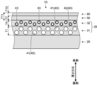
- Synthetic leather shows the state before embossing. It is a sectional view showing an example of a schematic structure of an upholstery material.
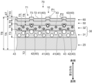
- Figure 2 shows the synthetic leather of Figure 1 after embossing; It is a side view which shows an example of a schematic structure of an embossing apparatus.
- the embossing device during the embossing step of the skin material manufacturing method is shown.
- the embossing die and the embossing receiving die have a roll shape.
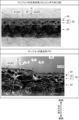
- Synthetic leather and upholstery represent the parts corresponding to the embossing device. It is a photograph of a vertical section of a synthetic leather and an upholstery material.
- the upper row is the synthetic leather of sample 1 used as a sample in the example, and shows the state before embossing.
- the lower part shows the skin material of sample 1 used as a sample in the example.
- the cutting direction of the synthetic leather in the upper stage and the upholstery material in the lower stage coincides with the thickness direction.
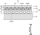
- FIG. 3 is a cross-sectional view showing another example of a schematic configuration of synthetic leather; Synthetic leather shows the state before embossing.
- FIG. 10 is a cross-sectional view showing another example of the schematic configuration of the skin material; Figure 6 shows the synthetic leather of Figure 5 after embossing;
- the synthetic leather 10 includes a fibrous base material 20, a porous resin layer 30, a nonporous resin layer 50, and a protective layer 60 (see FIG. 1).
- the porous resin layer 30 includes a first porous resin layer 31 and a second porous resin layer 32 .
- the synthetic leather 10 may include layers different from the porous resin layer 30 (the first porous resin layer 31 and the second porous resin layer 32), the nonporous resin layer 50 and the protective layer 60. good.
- An example of this different layer is an adhesive layer.
- the synthetic leather 10 forms the skin material 70 (see FIG. 2). That is, the upholstery material 70 includes the synthetic leather 10 .
- the skin material 70 is formed by embossing the synthetic leather 10 .
- the synthetic leather 10 has an uneven pattern 71 on the surface in the state of the skin material 70 .
- the skin material 70 can be used as a surface material for various products and parts.
- Examples of products and parts that can employ the skin material 70 include interior goods for transportation equipment, interior goods, shoes, bags and clothing.
- Transportation equipment includes automobiles, trains, aircraft and ships.
- the skin material 70 becomes the material forming the next part of the transportation equipment. Examples of such parts include ceilings, seats, dashboards, door linings and handles.
- Interior goods include furniture. Examples of furniture include sofas and chairs.
- the thickness direction of the synthetic leather 10, the fibrous base material 20, the porous resin layer 30, the nonporous resin layer 50, the protective layer 60 and the skin material 70 is referred to as "thickness direction" (Figs. reference).
- One side in the thickness direction is called the “front side”, and the other side in the thickness direction is called the “back side”.
- the surface on the front side in the thickness direction is called “front surface”, and the surface on the back side in the thickness direction is called “back surface”.
- the surface of synthetic leather 10 is the surface of skin material 70
- the back surface of synthetic leather 10 is the back surface of skin material 70 .
- the fibrous base material 20, the porous resin layer 30, the nonporous resin layer 50, and the protective layer 60 are composed of the protective layer 60, the nonporous resin layer 50, and the porous resin from the front side to the back side in the thickness direction.
- Layer 30 and fibrous base material 20 are laminated in that order.
- the first porous resin layer 31 and the second porous resin layer 32 are arranged from the front side to the back side in the thickness direction. are stacked in this order. That is, the porous resin layer 30 is laminated on the fibrous base material 20 .
- the first porous resin layer 31 is laminated on the fibrous base material 20 and the second porous resin layer 32 is laminated on the first porous resin layer 31 .
- the nonporous resin layer 50 is laminated on the porous resin layer 30 (second porous resin layer 32).
- a protective layer 60 is laminated on the non-porous resin layer 50 .
- the surface of the protective layer 60 forms the surface of the synthetic leather 10 and the surface of the upholstery material 70 .
- the back surface of the fibrous base material 20 forms the back surface of the synthetic leather 10 and the back surface of the skin material 70 .
- the fibrous base material 20 is a fibrous sheet material.
- fibrous substrates 20 include textile fabrics and natural leather. Examples of textile fabrics include wovens, knits and nonwovens. Natural leather includes split leather. However, from the viewpoint of the texture of the synthetic leather 10, the fibrous base material 20 is preferably a woven fabric or a knitted fabric, and more preferably a knitted fabric.
- Textture means the feel of holding an object. “Texture” is distinguished from "touch”. "Tactile” means the surface texture of an object.
- the fiber fabric may be coated or impregnated with a solvent-based or solvent-free polymeric compound, or may be dry-coagulated or wet-coagulated with a solvent-based or solvent-free polymeric compound. Solventless systems include water systems. Examples of polymer compounds include polyurethane resins and polyvinyl chloride resins.
- the density of the fibrous base material 20 is preferably 0.01-0.05 g/m 3 , more preferably 0.02-0.04 g/m 3 .
- the fibers forming the fiber fabric as the fibrous base material 20 are not particularly limited. Examples of such fibers include natural fibres, regenerated fibres, semi-synthetic fibres, and synthetic fibres.
- the fibers may be of one type or a combination of two or more types. However, from the viewpoint of strength and workability, the fibers are preferably synthetic fibers, more preferably polyester fibers, and still more preferably polyethylene terephthalate.
- the fibrous base material 20 may be colored with known dyes or pigments. Dyes or pigments are not particularly limited.
- the thickness of the fibrous base material 20 is not particularly limited. However, the thickness of the fibrous base material 20 is preferably 0.2 to 10 mm, more preferably 0.5 to 2 mm. By setting the thickness of the fibrous base material 20 to 0.2 mm or more, the synthetic leather 10 can be improved in shapeability and tactile feel. By setting the thickness of the fibrous base material 20 to 10 mm or less, the abrasion resistance of the synthetic leather 10 can be improved.
- the porous resin layer 30 has a plurality of holes 40 (see FIG. 1).
- the porous resin layer 30 contains a plurality of hollow particles 43 in the resin that serves as the base material of the porous resin layer 30 .
- Hollow particles 43 are fine particles and have holes 40 inside.
- the plurality of hollow particles 43 are dispersed in the resin that is the base material of the porous resin layer 30 .
- the porous resin layer 30 is preferably a laminate of two or more layers.
- the porous resin layer 30 is a two-layer laminate including a first porous resin layer 31 and a second porous resin layer 32 .
- the second porous resin layer 32 is provided on the front side of the first porous resin layer 31 in the thickness direction.
- the porous resin layer 30 is softer than a non-porous resin layer made of the same material and having the same thickness.
- This non-porous resin layer to be compared is different from the porous resin layer 30 in that it does not have the pores 40 and is the same as the porous resin layer 30 in other respects.
- the multiple holes 40 soften the porous resin layer 30 .
- the softness of the porous resin layer 30 improves the texture of the synthetic leather 10 .
- the thickness of the porous resin layer 30 is determined according to the thickness of the first porous resin layer 31 and the thickness of the second porous resin layer 32 . The thickness of the first porous resin layer 31 and the thickness of the second porous resin layer 32 will be described later.
- the first porous resin layer 31 has a plurality of first holes 41 (see FIG. 1).
- the multiple first holes 41 are part of the multiple holes 40 .
- the second porous resin layer 32 has a plurality of second holes 42 (see FIG. 1).
- the plurality of second holes 42 are part of the plurality of holes 40 .
- the second hole 42 is a hole 40 different from the first hole 41 .
- first hole 41 and the second hole 42 are not distinguished or are collectively referred to, they are referred to as "hole 40".
- the first hole 41 may be a closed space or an open space. However, from the viewpoint of abrasion resistance of the synthetic leather 10, the first hole 41 is preferably a closed space. By making the first hole 41 a closed space, it is possible to suppress the occurrence of cracks originating from the first hole 41 .
- the first hole 41 is assumed to be a closed space (see FIG. 1).
- the shape of the first hole 41 is not particularly limited. The shape of the first hole 41 may be fixed or irregular. A spherical shape is mentioned as an example of the shape of the first hole 41 .
- the spherical shape may be a true spherical shape or an elongated spherical shape.
- the plurality of first holes 41 are formed in the base material resin by known foam molding.
- the plurality of first holes 41 are dispersed in the resin that is the base material of the first porous resin layer 31 .
- Physical foaming, chemical foaming, and wet solidification are examples of methods for forming the plurality of first holes 41 .
- Physical foaming may utilize mechanical agitation.
- Chemical foaming may involve adding a foaming agent or utilizing a chemical reaction.
- the second hole 42 is a closed space (see Fig. 1). By making the second hole 42 a closed space, it is possible to suppress the occurrence of cracks originating from the second hole 42 . Furthermore, the second holes 42 are closed spaces inside the hollow particles 43 .
- the porous resin layer 30 contains a plurality of hollow particles 43 in the resin that is the base material of the second porous resin layer 32 .
- the hollow particles 43 in the second porous resin layer 32 have second holes 42 inside.
- the hollow particles 43 are dispersed in the resin that serves as the base material of the second porous resin layer 32 .
- the shape of the second hole 42 is not particularly limited. The shape of the second hole 42 may be regular or irregular.
- a spherical shape is mentioned as an example of the shape of the second hole 42 .
- the spherical shape may be a true spherical shape or an elongated spherical shape.
- the shape of the second hole 42 is preferably spherical.
- the hollow particles 43 have a spherical shape. As described above, the hollow particles 43 have microscopic spaces inside that serve as the second holes 42 .
- the coating that covers this space with hollow particles 43 is called the outer shell or outer wall. In embodiments, this coating is referred to as the "shell.” It is preferable that the hollow particles 43 have a property of not causing volume expansion or hardly causing volume expansion by heat treatment. By including the hollow particles 43 having such characteristics in the second porous resin layer 32, it is possible to suppress the volume change of the second porous resin layer 32 during the production of the synthetic leather 10, and further , variation in the shape, size and distribution of the plurality of second holes 42 can be suppressed.
- the hollow particles 43 are appropriately determined in consideration of the above characteristics.
- the hollow particles 43 include organic hollow particles having shells made of the following materials.
- the aforementioned materials include thermosetting resins and thermoplastic resins.
- thermosetting resins that form the shell include phenolic resins, epoxy resins and urea resins.
- thermoplastic resins that form the outer shell include acrylic resins and vinyl chloride resins.
- the hollow particles 43 include inorganic hollow particles having shells made of the following materials. Examples of the aforementioned materials include glass, shirasu, silica, alumina and carbon.
- the surfaces of organic hollow particles may be coated with inorganic fine powder. Examples of inorganic fine powder materials include calcium carbonate, talc and titanium oxide.
- the hollow particles 43 are preferably organic hollow particles of the first embodiment or the second embodiment.
- the aforementioned viewpoint is that the hollow particles 43 can be easily deformed by heating and pressing the synthetic leather 10 when the synthetic leather 10 is embossed. Furthermore, the aforementioned viewpoint is that the hollow particles 43 can retain their shape after being deformed.
- the organic hollow particles of the first aspect have an outer shell made of a thermoplastic resin.
- the organic hollow particles of the second aspect have a thermoplastic resin outer shell coated with an inorganic fine powder.
- the softening temperature of the thermoplastic resin is preferably 110 to 210°C, more preferably 130 to 190°C.
- the softening temperature of the thermoplastic resin that forms the outer shell of the hollow particles 43 can be measured by the following method. That is, the measuring device may be a thermomechanical analyzer (TMA2940) manufactured by TA Instruments. 250 ⁇ g of hollow particles 43 are placed in an aluminum cup with a diameter of 7 mm and a depth of 1 mm. After that, the hollow particles 43 in the cup are heated from above to 80 to 300° C. at a heating rate of 5° C./min while applying a force of 0.1 N from above. During the heating of the hollow particles 43, the vertical displacement of the applied indenter is continuously measured. The softening temperature is the temperature at which the maximum amount of displacement is exhibited.
- TMA2940 thermomechanical analyzer
- the hollow particles 43 may be formed using a microcapsule-type foaming agent as a material.
- a microcapsule-type foaming agent encloses a volatile foaming agent in the following outer shell.
- the aforementioned outer shell is made of a thermoplastic that can be softened and expanded by heat treatment. Examples of volatile blowing agents include low boiling hydrocarbons.
- a microcapsule-type foaming agent may be foamed in the composition liquid prepared in this step.
- the hollow particles 43 are preferably formed in advance using a microcapsule-type foaming agent as a material.
- a plurality of pre-formed hollow particles 43 are included in composition liquid B to form a plurality of second holes 42 .
- Composition liquid B is used in step B. Step B forms the second porous resin layer 32 . Process B and composition liquid B will be described later.
- the contents of the microcapsule-type foaming agent are preferably lower hydrocarbons with a boiling point of 0 to 100°C from the viewpoint of the shape retention of the microcapsules in a low-temperature environment.
- examples of such inclusions include butane, isobutane, pentane, isopentane and neopentane.
- the plurality of hollow particles 43 in the second porous resin layer 32 may be of one type, or may be a combination of two or more types. It is assumed that the plurality of hollow particles 43 in the second porous resin layer 32 are a combination of two or more types. In this case, the two or more types of hollow particles 43 preferably have spaces of the same shape inside.
- the plurality of second holes 42 can have the same shape.
- the first hole 41 has a major diameter of the first dimension. Assume that the first hole 41 is a closed space having a spherical shape. In this case, the major diameter of the first hole 41 matches the diameter of the spherical first hole 41 . Assume that the first hole 41 is a closed space having a shape different from a true sphere. In this case, the length of the first hole 41 corresponds to the maximum dimension of the first hole 41 .
- the second bore 42 has a major diameter of a second dimension. Assume that the second hole 42 is a closed space having a spherical shape. In this case, the length of the second hole 42 matches the diameter of the spherical second hole 42 . Assume that the second hole 42 is a closed space having a shape different from a true sphere. In this case, the length of the second hole 42 corresponds to the maximum dimension of the second hole 42 .
- the first dimension of the major axis of the first hole 41 and the second dimension of the major axis of the second hole 42 preferably have the following values. That is, the first dimension of the major axis of the first hole 41 is preferably 320 ⁇ m or less, more preferably 100 to 280 ⁇ m.
- the second dimension of the major axis of the second hole 42 is preferably 200 ⁇ m or less, more preferably 50 to 80 ⁇ m.
- the relationship between the first dimension and the second dimension in the synthetic leather 10 before embossing is preferably set to "first dimension>second dimension".
- the first dimension of the major axis of the first hole 41 and the second dimension of the major axis of the second hole 42 preferably have the following values. That is, the first dimension of the major axis of the first hole 41 is smaller than before the embossing in the area of the concave portions 72 of the uneven pattern 71, preferably 260 ⁇ m or less, more preferably 180 ⁇ m or less.
- the first holes 41 may disappear in the areas of the recesses 72 of the textured pattern 71 .
- the first dimension of the major axis of the first hole 41 is preferably 320 ⁇ m or less, more preferably 100 to 280 ⁇ m, in the region of the projections 73 of the uneven pattern 71, the same as before embossing.
- the second dimension of the major axis of the second hole 42 is smaller than before the embossing in the region of the recesses 72 of the uneven pattern 71, preferably 150 ⁇ m or less, more preferably 40 ⁇ m or less.
- the second holes 42 may disappear in the areas of the recesses 72 of the uneven pattern 71 .
- the second dimension of the major axis of the second hole 42 is preferably 200 ⁇ m or less, more preferably 50 to 80 ⁇ m, in the area of the projections 73 of the uneven pattern 71, as before embossing.
- the first porous resin layer 31 is made of polyurethane resin as a base material.
- Polyurethane resin is a general term for the following polyurethanes and resins containing this polyurethane as a main component.
- the aforementioned polyurethane is a polymer compound having urethane bonds in its main chain.
- the polyurethane resin that is the base material of the first porous resin layer 31 may be a copolymer containing urethane bonds, or a mixture of polyurethane and other resins. Examples of copolymers containing urethane bonds include acrylic urethane resins.
- the polyurethane resin used as the base material of the first porous resin layer 31 is not particularly limited.
- this polyurethane resin examples include polycarbonate-based polyurethane resins, polyether-based polyurethane resins and polyester-based polyurethane resins. From the viewpoint of the durability of the synthetic leather 10, this polyurethane resin is preferably a polycarbonate-based polyurethane resin. Polycarbonate-based polyurethane resins are harder and more heat-resistant than polyether-based polyurethane resins and polyester-based polyurethane resins.
- the polyurethane resin that is the base material of the first porous resin layer 31 may be solvent-free (solvent-free), solvent-based, or water-based, and is not particularly limited in this respect. Furthermore, the polyurethane resin may be of the one-part or two-part type. However, from the viewpoint of environmental load, this polyurethane resin is preferably solvent-free (solvent-free), and from the viewpoint of ease of forming a porous layer by chemical foaming, it should be a two-liquid type. is preferred.
- the first porous resin layer 31 is formed by the composition liquid A.
- Composition liquid A is used in step A.
- Process A forms the first porous resin layer 31 .
- Composition liquid A may contain an additive. Additives are contained within a range that does not impair the physical properties to be imparted to the first porous resin layer 31 . Examples of additives include crosslinkers, catalysts, leveling agents, pigments and matting agents. One type of additive may be used, or two or more types may be used.
- composition liquid A may contain the following solvents. Examples of the aforementioned solvents include organic solvents. Preferably, the solvent is methyl ethyl ketone or dimethyl sulfoxide. Process A and composition liquid A will be described later.
- the second porous resin layer 32 uses a polyurethane resin as a base material.
- the polyurethane resin that is the base material of the second porous resin layer 32 is preferably a polycarbonate-based polyurethane resin, a polyether-based polyurethane resin, or a polyester-based polyurethane resin.
- This polyurethane resin is preferably a polycarbonate-based polyurethane resin from the viewpoint of the durability of the synthetic leather 10, and preferably a polyether-based polyurethane resin from the viewpoint of texture.
- the polyurethane resin that is the base material of the second porous resin layer 32 may be solvent-free (solvent-free), solvent-based, or water-based, and is not particularly limited in this respect. Furthermore, the polyurethane resin may be of the one-part or two-part type. However, this polyurethane resin is preferably solvent-free (solvent-free) or water-based from the viewpoint of environmental load. A mold is preferred.
- Composition liquid B may contain additives. Additives are contained within a range that does not impair the physical properties to be imparted to the second porous resin layer 32 .
- additives include crosslinkers, catalysts, leveling agents, pigments, matting agents, leveling agents, surfactants, fillers and thickeners.
- One type of additive may be used, or two or more types may be used.
- composition liquid B may contain the following solvents. Examples of the aforementioned solvents include highly polar solvents. This solvent is preferably water from the viewpoint of environmental load.
- the softening temperature of the first porous resin layer 31 is the first temperature.
- the first temperature is preferably a predetermined value in the range of 170-225°C.
- the softening temperature of the second porous resin layer 32 is the second temperature.
- the second temperature is preferably a predetermined value in the range of 120-170°C.
- the second temperature is preferably lower than the first temperature. In this case, the temperature difference between the first temperature and the second temperature is preferably 45-75°C.
- thicknesses T1, T2, and T3 are specified as the thickness of the first porous resin layer 31.
- the thickness T1 of the first porous resin layer 31 is intended for the synthetic leather 10 before embossing (see FIG. 1).
- the thicknesses T2 and T3 of the first porous resin layer 31 are intended for the synthetic leather 10 after embossing (see FIG. 2).
- the synthetic leather 10 after embossing can also be called the synthetic leather 10 in the skin material 70 .
- the thickness T ⁇ b>2 of the first porous resin layer 31 targets the area of the concave portions 72 of the uneven pattern 71 .
- the thickness T3 of the first porous resin layer 31 targets the area of the convex portions 73 of the uneven pattern 71 .
- the thicknesses T1, T2, and T3 of the first porous resin layer 31 are appropriately determined in consideration of various conditions.
- the thickness T1 of the first porous resin layer 31 is preferably 100-320 ⁇ m, more preferably 160-280 ⁇ m.
- the thickness T2 of the first porous resin layer 31 is thinner than the thickness T1 of the first porous resin layer 31, preferably 100-260 ⁇ m, more preferably 140-200 ⁇ m.
- the thickness T2 of the first porous resin layer 31 By setting the thickness T2 of the first porous resin layer 31 to 100 ⁇ m or more, the texture of the synthetic leather 10 can be improved.
- the thickness T2 of the first porous resin layer 31 By setting the thickness T2 of the first porous resin layer 31 to 260 ⁇ m or less, the depth of the concave portion 72 can be improved. Setting the thickness T2 of the first porous resin layer 31 to 260 ⁇ m or less contributes to making the edge of the uneven pattern 71 sharp, thereby further improving the design of the surface material 70 .
- the thickness T3 of the first porous resin layer 31 is preferably 100 to 320 ⁇ m, more preferably 160 to 280 ⁇ m.
- the synthetic leather 10 can be improved in shapeability and tactile feel.
- the abrasion resistance of the synthetic leather 10 can be improved by setting the thickness T3 of the first porous resin layer 31 to 320 ⁇ m or less.
- the thickness T1 of the first porous resin layer 31 can be specified by a known measuring method for the synthetic leather 10 before embossing.
- the thickness T1 of the first porous resin layer 31 may be specified by the following method. That is, the thickness T1 of the first porous resin layer 31 may be the average value of the following 10 measured values.
- the 10 measurement values described above are obtained by measuring the first porous resin layer 31 at 10 arbitrary points on the synthetic leather 10 before embossing.
- the number of measured values "10" is an example. This number of measured values is appropriately determined in consideration of various conditions.
- the thickness T1 of the first porous resin layer 31 may not be the average value.
- the thickness T2 of the first porous resin layer 31 can be specified by a known measurement method for the synthetic leather 10 after embossing.
- the thickness T2 of the first porous resin layer 31 may be specified by the following method. That is, the thickness T2 of the first porous resin layer 31 may be the average value of the following 20 measured values.
- the aforementioned 20 measured values are obtained by measuring the first porous resin layer 31 of the synthetic leather 10 after embossing at arbitrary 10 recesses 72 of the uneven pattern 71 . In this case, the number of measurements in one concave portion 72 is two.
- the number of measured values “20”, the number of the recesses 72 to be measured “10”, and the number of measured values for one recess 72 “2” are examples. These numbers are appropriately determined in consideration of various conditions.
- the thickness T2 of the first porous resin layer 31 may not be an average value.
- the thickness T3 of the first porous resin layer 31 can be specified by a known measuring method for the synthetic leather 10 after embossing.
- the thickness T3 of the first porous resin layer 31 may be specified by the following method. That is, the thickness T3 of the first porous resin layer 31 may be the average value of the following 20 measured values.
- the 20 measurement values described above are obtained by measuring the first porous resin layer 31 of the synthetic leather 10 after embossing with arbitrary 10 convex portions 73 of the uneven pattern 71 . In this case, the number of measurements for one convex portion 73 is two.
- the number of measured values “20”, the number of convex portions 73 to be measured “10”, and the number of measured values for one convex portion 73 “2” are examples. These numbers are appropriately determined in consideration of various conditions.
- the thickness T3 of the first porous resin layer 31 may not be the average value.
- the thickness T1 of the first porous resin layer 31 may be measured by enlarging the first porous resin layer 31 in the vertical cross section of the synthetic leather 10 before embossing.
- the thickness T2 of the first porous resin layer 31 may be measured by enlarging the first porous resin layer 31 in the region of the concave portion 72 in the vertical cross section of the synthetic leather 10 after embossing.
- the thickness T3 of the first porous resin layer 31 may be measured by enlarging the first porous resin layer 31 in the area of the protrusions 73 in the vertical cross section of the synthetic leather 10 after embossing.
- the cutting direction of the synthetic leather 10 coincides with the thickness direction.
- a microscope may be used for magnification. Examples of microscopes include scanning electron microscopes.
- the enlargement rate is appropriately determined in consideration of various conditions.
- the thicknesses T1, T2 and T3 of the first porous resin layer 31 may be measured using a scanning electron microscope (S-3000N) manufactured by Hitachi High-Technologies Corporation. In this case, the magnification may be 300 times.
- the enlargement rate is appropriately determined in consideration of various conditions.
- the compressibility of the first porous resin layer 31 is preferably 20% or less.
- the compressibility of the first porous resin layer 31 is obtained by " ⁇ (T3-T2)/T3 ⁇ 100".
- thicknesses T4, T5, and T6 are specified as the thickness of the second porous resin layer 32.
- the thickness T4 of the second porous resin layer 32 is intended for the synthetic leather 10 before embossing (see FIG. 1).
- the thicknesses T5 and T6 of the second porous resin layer 32 are intended for the synthetic leather 10 after embossing (see FIG. 2).
- the synthetic leather 10 after embossing can also be called the synthetic leather 10 in the skin material 70 as described above.
- the thickness T5 of the second porous resin layer 32 targets the region of the concave portions 72 of the uneven pattern 71 .
- the thickness T6 of the second porous resin layer 32 targets the area of the convex portions 73 of the uneven pattern 71 .
- the thicknesses T4, T5, and T6 of the second porous resin layer 32 are appropriately determined in consideration of various conditions.
- the thickness T4 of the second porous resin layer 32 is preferably 20-300 ⁇ m, more preferably 65-85 ⁇ m.
- the thickness T4 of the second porous resin layer 32 can be measured according to the method for measuring the thickness T1 of the first porous resin layer 31 described above.
- the thickness T5 of the second porous resin layer 32 is thinner than the thickness T4 of the second porous resin layer 32, preferably 10-150 ⁇ m, more preferably 40-70 ⁇ m.
- the thickness T5 of the second porous resin layer 32 can be measured according to the method for measuring the thickness T2 of the first porous resin layer 31 described above.
- the thickness T6 of the second porous resin layer 32 is preferably 20 to 300 ⁇ m, more preferably 65 to 85 ⁇ m.
- the depth of the concave portion 72 can be improved.
- Setting the thickness T6 of the second porous resin layer 32 to 20 ⁇ m or more contributes to making the edge of the concave-convex pattern 71 sharp, thereby further improving the design of the surface material 70 .
- the thickness T6 of the second porous resin layer 32 By setting the thickness T6 of the second porous resin layer 32 to 300 ⁇ m or less, the abrasion resistance of the synthetic leather 10 can be improved.
- the thickness T6 of the second porous resin layer 32 can be measured according to the method for measuring the thickness T3 of the first porous resin layer 31 described above. In FIG. 2 and FIG. 6 described later, the second porous resin layer 32 is drawn with the same thicknesses T5 and T6.
- the compressibility of the second porous resin layer 32 is preferably 40-55%.
- the compressibility of the second porous resin layer 32 is obtained by " ⁇ (T6-T5)/T6 ⁇ 100".
- the nonporous resin layer 50 hides the porous resin layer 30 on the front side in the thickness direction. Furthermore, the non-porous resin layer 50 colors the surface of the synthetic leather 10 in a desired color.
- the base material of the nonporous resin layer 50 may be the same resin as the base material of the first porous resin layer 31 . From the viewpoint of abrasion resistance and texture of the synthetic leather 10, the resin that is the base material of the non-porous resin layer 50 is preferably a polycarbonate-based polyurethane resin.
- the resin serving as the base material of the non-porous resin layer 50 may be solvent-free (solvent-free), solvent-based, or water-based, and is not particularly limited in this respect.
- the non-porous resin layer 50 contains a coloring agent in the base resin. This coloring agent is not particularly limited. Examples of colorants include pigments. Examples of pigments include inorganic pigments and organic pigments.
- the nonporous resin layer 50 may contain a known pigment as a coloring agent. A pigment is included in composition liquid C. Composition liquid C is used in step C. Process C forms a non-porous resin layer 50 . Process C and composition liquid C will be described later.
- the content of the coloring agent is not particularly limited, and is determined as appropriate in consideration of various conditions.
- the content of the coloring agent may be appropriately determined according to the desired color of the synthetic leather 10 .
- the content of the colorant is preferably 5 to 25% by mass, more preferably 10 to 20% by mass, in terms of solid content, relative to the entire liquid composition C.
- the concealability of the porous resin layer 30 and the colorability of the surface of the synthetic leather 10 can be enhanced.
- a viewer of the upholstery material 70 can recognize the color of the surface of the synthetic leather 10 as a design provided on the surface of the upholstery material 70 .
- the content of the colorant By setting the content of the colorant to 25% by mass or less, a decrease in the strength of the nonporous resin layer 50 can be suppressed. By suppressing a decrease in the strength of the nonporous resin layer 50, the wear resistance of the synthetic leather 10 can be improved.
- the composition liquid C may contain additives. Additives are contained within a range that does not impair the physical properties to be imparted to the nonporous resin layer 50 . Examples of additives include leveling agents, cross-linking agents, matting agents and leveling agents. One type of additive may be used, or two or more types may be used. Furthermore, composition liquid C may contain the following solvents. Examples of the aforementioned solvents include highly polar solvents. This solvent is preferably water from the viewpoint of environmental load.
- the softening temperature of the non-porous resin layer 50 is the third temperature.
- the third temperature is preferably higher than the first temperature, which is the softening temperature of the first porous resin layer 31 . That is, the relationship among the first temperature, the second temperature (the softening temperature of the second porous resin layer 32) and the third temperature is preferably "third temperature>first temperature>second temperature".
- the third temperature is preferably a predetermined value in the range of 190-240.degree.
- thicknesses T7, T8, and T9 are specified as the thickness of the nonporous resin layer 50.
- the thickness T7 of the non-porous resin layer 50 is intended for the synthetic leather 10 before embossing (see FIG. 1).
- the thicknesses T8 and T9 of the non-porous resin layer 50 are intended for the synthetic leather 10 after embossing (see FIG. 2).
- the synthetic leather 10 after embossing can also be called the synthetic leather 10 in the skin material 70 as described above.
- the thickness T8 of the non-porous resin layer 50 targets the region of the concave portions 72 of the uneven pattern 71 .
- the thickness T9 of the non-porous resin layer 50 targets the area of the convex portions 73 of the uneven pattern 71 .
- the thicknesses T7, T8, and T9 of the non-porous resin layer 50 are appropriately determined in consideration of various conditions.
- the thickness T7 of the non-porous resin layer 50 is preferably 20-80 ⁇ m, more preferably 25-50 ⁇ m.
- the thickness T7 of the nonporous resin layer 50 can be measured according to the method for measuring the thickness T1 of the first porous resin layer 31 described above.
- the thickness T8 of the nonporous resin layer 50 is thinner than the thickness T7 of the nonporous resin layer 50, preferably 15 to 60 ⁇ m, more preferably 15 to 40 ⁇ m.
- the thickness T8 of the nonporous resin layer 50 can be measured according to the method for measuring the thickness T2 of the first porous resin layer 31 described above.
- the thickness T9 of the nonporous resin layer 50 is preferably 20 to 80 ⁇ m, more preferably 25 to 50 ⁇ m.
- the concealability of the porous resin layer 30 and the colorability of the surface of the synthetic leather 10 can be enhanced.
- a viewer of the upholstery material 70 can recognize the color of the surface of the synthetic leather 10 as a design provided on the surface of the upholstery material 70 .
- the thickness T9 of the non-porous resin layer 50 By setting the thickness T9 of the non-porous resin layer 50 to 80 ⁇ m or less, the shapeability of the synthetic leather 10 can be improved.
- the thickness T9 of the nonporous resin layer 50 can be measured according to the method for measuring the thickness T3 of the first porous resin layer 31 described above. In FIG. 2 and FIG. 6 described later, the nonporous resin layer 50 is drawn with the same thicknesses T8 and T9.
- the compressibility of the nonporous resin layer 50 is preferably 40% or less.
- the compressibility of the non-porous resin layer 50 is obtained by " ⁇ (T9-T8)/T9 ⁇ 100".
- the protective layer 60 protects the synthetic leather 10 on the front side in the thickness direction.
- the protective layer 60 improves the wear resistance of the synthetic leather 10 .
- the protective layer 60 may use the same resin as the base material of the first porous resin layer 31 as the base material.
- the resin that is the base material of the protective layer 60 is preferably a polycarbonate-based polyurethane resin.
- the resin that is the base material of the protective layer 60 may be solvent-free (solvent-free), solvent-based, or water-based, and is not particularly limited in this respect.
- Composition liquid D may contain an additive.
- Composition liquid D is used in step D.
- Process D forms a protective layer 60 .
- additives include leveling agents, cross-linking agents, matting agents and leveling agents. One type of additive may be used, or two or more types may be used. Process D and composition liquid D will be described later.
- the thickness T10 (see FIGS. 1 and 2) of the protective layer 60 is not particularly limited. However, the thickness T10 of the protective layer 60 is preferably 1 to 50 ⁇ m, more preferably 3 to 20 ⁇ m. By setting the thickness of the protective layer 60 to 1 ⁇ m or more, the abrasion resistance of the synthetic leather 10 can be enhanced. By setting the thickness of the protective layer 60 to 50 ⁇ m or less, the shapeability of the synthetic leather 10 can be improved. The inventors know that the thickness T10 of the protective layer 60 does not change or is difficult to change before and after embossing.
- the total thickness T11 of the nonporous resin layer 50 and the protective layer 60 is not particularly limited.
- the total thickness T11 is the sum of the thickness T7 of the nonporous resin layer 50 and the thickness T10 of the protective layer 60 (see FIG. 1).
- the total thickness T11 of the nonporous resin layer 50 and the protective layer 60 is preferably 21 to 130 ⁇ m, more preferably 28 to 70 ⁇ m, from the viewpoint of shaping the synthetic leather 10.
- the total thickness T11 of the nonporous resin layer 50 and the protective layer 60 is preferably 21 to 130 ⁇ m, more preferably 28 to 70 ⁇ m, from the viewpoint of shaping the synthetic leather 10.
- the synthetic leather 10 exhibits the above-described functions both before and after embossing, except for the specific functions targeted before embossing.
- the skin material 70 including the synthetic leather 10 exhibits the same function as the synthetic leather 10, or the synthetic leather 10 with the skin material 70 exhibits the same function as before embossing.
- the texture of the synthetic leather 10 can be rephrased as the texture of the skin material 70
- the wear resistance of the synthetic leather 10 can be rephrased as the wear resistance of the skin material 70
- the durability of the synthetic leather 10 can be rephrased as the skin.
- the durability of the material 70 can be rephrased
- the tactile sensation of the synthetic leather 10 can be rephrased as the tactile sensation of the upholstery material 70 .
- the manufacturing method of the synthetic leather 10 includes four steps A, B, C and D.
- a fibrous base material 20 is prepared when carrying out the method for manufacturing the synthetic leather 10 .
- step A the first porous resin layer 31 is formed as described above.
- step A composition liquid A is applied and composition liquid A is solidified.
- the composition liquid A solidifies to form the first porous resin layer 31 .
- step B forms the second porous resin layer 32 as described above.
- step B composition liquid B is applied and composition liquid B is solidified.
- the composition liquid B solidifies to form the second porous resin layer 32 .
- Process C forms the non-porous resin layer 50 as described above.
- step C the composition liquid C is applied and the composition liquid C is solidified.
- the composition liquid C solidifies to form the nonporous resin layer 50 .
- Process D forms the protective layer 60 as described above.
- step D the composition liquid D is applied and the composition liquid D is solidified.
- the composition liquid D solidifies to form the protective layer 60 .
- Step A may include a procedure for preparing composition liquid A.
- Step B may include a procedure for preparing composition liquid B.
- Step C may include a procedure for preparing composition liquid C.
- Step D may include a procedure for preparing composition liquid D.
- step A prepares composition liquid A
- step B prepares composition liquid B
- step C prepares composition liquid C
- step D prepares composition liquid D.
- the composition liquid A may be prepared in advance before the step A is carried out.
- step A composition liquid A prepared in advance may be used.
- the composition liquid B may be prepared in advance before the step B is performed.
- step B composition liquid B prepared in advance may be used.
- the composition liquid C may be prepared in advance before the step C is performed.
- step C composition liquid C prepared in advance may be used.
- the composition liquid D may be prepared in advance before the step D is performed.
- step D composition liquid D prepared in advance may be used.
- Composition liquids A to D are applied by a known application method.
- application methods include knife coating, roll coating, gravure coating and spray coating.
- the coating method may be different in some or all of steps A to D, or may be the same in all of steps A to D.
- the coating method employed in steps A to D is appropriately determined in consideration of various conditions.
- the embodiment exemplifies the first manufacturing method, the second manufacturing method, the third manufacturing method, the fourth manufacturing method, and the fifth manufacturing method as the manufacturing method of the synthetic leather 10.
- steps A to D are performed in the order of step A, step B, step C and step D. That is, in step A, the composition liquid A is applied onto the fibrous base material 20, and then the composition liquid A is dry-coagulated. The surface of the fibrous base material 20 to which the liquid composition A is applied is the surface.
- a first intermediate is formed by laminating a first porous resin layer 31 on the front side of the fibrous base material 20 in the thickness direction.
- step B the composition liquid B is applied onto the first intermediate, and then the composition liquid B is dry solidified.
- the surface of the first intermediate on which the liquid composition B is applied is the surface of the first porous resin layer 31 .
- step B a second intermediate is formed by laminating a second porous resin layer 32 on the front side in the thickness direction of the first intermediate.
- step C the composition liquid C is applied onto the second intermediate, and then the composition liquid C is dry solidified.
- the surface of the second intermediate on which the liquid composition C is applied is the surface of the second porous resin layer 32 .
- step C a third intermediate is formed by laminating a nonporous resin layer 50 on the front side in the thickness direction of the second intermediate.
- step D the composition liquid D is applied onto the third intermediate, and then the composition liquid D is dry solidified.
- the surface of the third intermediate to which the liquid composition D is applied is the surface of the nonporous resin layer 50 .
- step D a laminate is formed by laminating the protective layer 60 on the front side in the thickness direction of the third intermediate. This laminate forms synthetic leather 10 .
- steps A to D are performed in the order of step C, step B, step A and step D. That is, in step C, the composition liquid C is applied onto the releasable base material, and then the composition liquid C is dry solidified.
- the surface of the release base material to which the composition liquid C is applied has a shape that is the reverse of the uneven shape of the textured pattern. Examples of release substrates include release paper.
- a first intermediate is formed by laminating a nonporous resin layer 50 on a releasable base material.
- step B the composition liquid B is applied onto the first intermediate, and then the composition liquid B is dry solidified.
- the surface of the first intermediate to which composition liquid B is applied is the back surface of nonporous resin layer 50 .
- step B a second intermediate is formed by laminating a second porous resin layer 32 on the back side of the first intermediate in the thickness direction.
- step A composition liquid A is applied onto the second intermediate.
- the surface of the second intermediate to which the composition liquid A is applied is the back surface of the second porous resin layer 32 .
- step A the first porous resin layer 31 and the fibrous base material 20 are pressure-bonded in a state in which the composition liquid A after application as the first porous resin layer 31 has viscosity.
- step A the release substrate is peeled off.
- Step A is a third intermediate in which the nonporous resin layer 50, the second porous resin layer 32, the first porous resin layer 31, and the fibrous base material 20 are laminated from the front side to the back side in the thickness direction.
- step D the composition liquid D is applied onto the third intermediate, and then the composition liquid D is dry solidified.
- the surface of the third intermediate to which the liquid composition D is applied is the surface of the nonporous resin layer 50 .
- step D a laminate is formed by laminating the protective layer 60 on the front side in the thickness direction of the third intermediate. This laminate forms synthetic leather 10 .
- steps A to D are performed in the order of step C, step B, step A and step D. That is, in step C, the composition liquid C is applied onto the releasable base material, and then the composition liquid C is dry solidified.
- the surface of the release base material to which the composition liquid C is applied has a shape that is the reverse of the uneven shape of the textured pattern. Examples of release substrates include release paper.
- a first intermediate is formed by laminating a nonporous resin layer 50 on a releasable base material.
- step B the composition liquid B is applied onto the first intermediate, and then the composition liquid B is dry solidified.
- the surface of the first intermediate to which composition liquid B is applied is the back surface of nonporous resin layer 50 .
- step B a second intermediate is formed by laminating a second porous resin layer 32 on the back side of the first intermediate in the thickness direction.
- step A the composition liquid A is applied onto the second intermediate, and then the composition liquid A is dry solidified.
- the surface of the second intermediate to which the composition liquid A is applied is the back surface of the second porous resin layer 32 .
- step A an adhesive is applied onto the first porous resin layer 31 to bond the first porous resin layer 31 and the fibrous base material 20 together.
- An adhesive is applied to the back surface of the first porous resin layer 31 .
- step A the release substrate is peeled off.
- Step A is a third intermediate in which the nonporous resin layer 50, the second porous resin layer 32, the first porous resin layer 31, and the fibrous base material 20 are laminated from the front side to the back side in the thickness direction. to form
- step D the composition liquid D is applied onto the third intermediate, and then the composition liquid D is dry solidified.
- the surface of the third intermediate to which the liquid composition D is applied is the surface of the nonporous resin layer 50 .
- step D a laminate is formed by laminating the protective layer 60 on the front side in the thickness direction of the third intermediate. This laminate forms synthetic leather 10 .
- This synthetic leather 10 includes an adhesive layer between the fibrous base material 20 and the first porous resin layer 31 .
- steps A to D are performed in the order of step D, step C, step B and step A. That is, in step D, the composition liquid D is applied onto the releasable substrate, and then the composition liquid D is dry solidified.
- the shape of the surface of the release substrate to which the composition liquid D is applied is appropriately determined in consideration of various conditions. Examples of release substrates include release paper. When the release substrate is a release paper, the shape of the surface of the release paper to which the liquid composition D is applied may be either smooth or uneven.
- a first intermediate is formed by laminating a protective layer 60 on a releasable base material.
- step C the composition liquid C is applied onto the first intermediate, and then the composition liquid C is dry solidified.
- the surface of the first intermediate to which the liquid composition C is applied is the back surface of the protective layer 60 .
- step C a second intermediate is formed by laminating a nonporous resin layer 50 on the back side of the first intermediate in the thickness direction.
- step B composition liquid B is applied onto the second intermediate.
- the surface of the second intermediate to which composition liquid B is applied is the back surface of nonporous resin layer 50 .
- step B a third intermediate is formed by laminating the second porous resin layer 32 on the back side of the second intermediate in the thickness direction.
- step A composition liquid A is applied onto the third intermediate.
- the surface of the third intermediate to which composition liquid A is applied is the back surface of second porous resin layer 32 .
- step A the first porous resin layer 31 and the fibrous base material 20 are pressure-bonded in a state in which the composition liquid A after application as the first porous resin layer 31 has viscosity.
- step A the release substrate is peeled off.
- step A the protective layer 60, the nonporous resin layer 50, the second porous resin layer 32, the first porous resin layer 31, and the fibrous base material 20 are laminated from the front side to the back side in the thickness direction. Form a laminate. This laminate forms synthetic leather 10 .
- steps A to D are performed in the order of step D, step C, step B and step A. That is, in step D, the composition liquid D is applied onto the releasable substrate, and then the composition liquid D is dry solidified.
- the shape of the surface of the release substrate to which the composition liquid D is applied is appropriately determined in consideration of various conditions. Examples of release substrates include release paper. When the release substrate is a release paper, the shape of the surface of the release paper to which the liquid composition D is applied may be either smooth or uneven.
- a first intermediate is formed by laminating a protective layer 60 on a releasable base material.
- step C the composition liquid C is applied onto the first intermediate, and then the composition liquid C is dry solidified.
- the surface of the first intermediate to which the liquid composition C is applied is the back surface of the protective layer 60 .
- step C a second intermediate is formed by laminating a nonporous resin layer 50 on the back side of the first intermediate in the thickness direction.
- step B composition liquid B is applied onto the second intermediate.
- the surface of the second intermediate to which composition liquid B is applied is the back surface of nonporous resin layer 50 .
- step B a third intermediate is formed by laminating the second porous resin layer 32 on the back side of the second intermediate in the thickness direction.
- step A the composition liquid A is applied onto the third intermediate, and then the composition liquid A is dry solidified.
- the surface of the third intermediate to which composition liquid A is applied is the back surface of second porous resin layer 32 .
- step A an adhesive is applied onto the first porous resin layer 31 to bond the first porous resin layer 31 and the fibrous base material 20 together.
- An adhesive is applied to the back surface of the first porous resin layer 31 .
- step A the release substrate is peeled off.
- step A the protective layer 60, the nonporous resin layer 50, the second porous resin layer 32, the first porous resin layer 31, and the fibrous base material 20 are laminated from the front side to the back side in the thickness direction. Form a laminate.
- This laminate forms synthetic leather 10 .
- This synthetic leather 10 includes an adhesive layer between the fibrous base material 20 and the first porous resin layer 31 .
- ⁇ Method for manufacturing skin material 70 and embossing device 80 A method of manufacturing the skin material 70 and the embossing device 80 will be described with reference to FIGS. In this explanation, it is assumed that the synthetic leather 10 is a long sheet material. In this case, the skin material 70 also becomes a long sheet material. However, the synthetic leather 10 and the skin material 70 may be short sheet materials. As the direction for specifying the embossing device 80, the above-described thickness direction (front side and back side) is used.
- the method of manufacturing the skin material 70 includes an embossing process. The embossing process is performed by the embossing device 80 .
- the embossing device 80 embosses the raw synthetic leather 10 (see FIG. 1) in an embossing process.
- the embossing device 80 includes an embossing die 81, an embossing receiving die 85, and a heater 86 (see FIG. 3).
- the embossing die 81 has a roll shape.
- the embossing receiving die 85 has a roll shape.
- the embossing die 81 and the embossing receiving die 85 are provided side by side in the thickness direction.
- the embossing die 81 is provided on the front side of the synthetic leather 10 in the thickness direction.
- the embossing receiving die 85 is provided on the back side of the synthetic leather 10 in the thickness direction.
- the embossing device 80 includes a supply device 87 and a collection device 88 (see FIG. 3).
- the supply device 87 and the recovery device 88 are intended for the synthetic leather 10 and the skin material 70 having the form of long sheet materials.
- a supply device 87 supplies raw synthetic leather 10 to the embossing die 81 and the embossing receiving die 85 .
- a recovery device 88 recovers the skin material 70 .
- the embossing device 80 can employ a feeding device and a collecting device similar to known embossing devices as a feeding device 87 and a collecting device 88 . Therefore, other descriptions of the supply device 87 and the recovery device 88 are omitted.
- the synthetic leather 10 and the upholstery material 70 continue from the supply device 87 to the recovery device 88 and are conveyed from the supply device 87 to the recovery device 88 .
- the synthetic leather 10 passes between the embossing die 81 and the embossing receiving die 85 on the way from the feeding device 87 to the collecting device 88, and is formed into the skin material 70 (embossing step).
- the direction in which the synthetic leather 10 and the upholstery material 70 are conveyed is called "conveyance direction".
- Both the embossing die 81 and the embossing receiving die 85 have a roll shape. In this case, the embossing die 81 and the embossing receiving die 85 rotate in a direction corresponding to the conveying direction.
- the direction of rotation of the embossing receiving die 85 is opposite to the direction of rotation of the embossing die 81 .
- the circular arc arrow in the embossing die 81 indicates the rotation direction of the embossing die 81
- the circular arc arrow in the embossing receiving die 85 indicates the rotating direction of the embossing receiving die 85 .
- the embossing die 81 includes a molding portion 82 .
- the molded portion 82 has a concave-convex shape obtained by inverting the concave-convex shape of the concave-convex pattern 71 .
- the forming part 82 contacts the surface of the synthetic leather 10 and presses the surface of the synthetic leather 10 when the synthetic leather 10 passes between the embossing die 81 and the embossing receiving die 85 .
- Molded portion 82 includes a convex portion 83 and a concave portion 84 .
- the convex portion 83 has a shape corresponding to the concave portion 72 of the uneven pattern 71 and bites into the surface of the synthetic leather 10 .
- the concave portion 84 has a shape corresponding to the convex portion 73 of the uneven pattern 71 .
- the following portions of the synthetic leather 10 enter into the recesses 84 .
- the aforementioned portions form the convex portions 73 of the relief pattern 71 .
- the embossing receiving mold 85 is in contact with the back surface of the synthetic leather 10 when the synthetic leather 10 passes between the embossing processing mold 81 and the embossing receiving mold 85, and supports the synthetic leather 10 from the back side in the thickness direction.
- the embossing receiving die 85 may have the following surfaces made of an elastic material. The aforementioned surface contacts the back surface of the synthetic leather 10 when the synthetic leather 10 passes between the embossing die 81 and the embossing receiving die 85 .
- the surface of the embossing receiving mold 85 that contacts the back surface of the synthetic leather 10 is referred to as "the outer surface of the embossing receiving mold 85".
- the outer surface of the embossing receiving die 85 may be a smooth surface. "Smooth" means without undulations or unevenness.
- Examples of elastic materials forming the outer surface of the embossing receiving die 85 include rubber, thermoplastic elastomers and plastics.
- Examples of the rubber forming the outer surface of the embossing receiving die 85 include silicone rubber, nitrile rubber, chloroprene rubber, ethylene-propylene rubber, butyl rubber, urethane rubber, fluororubber and natural rubber.
- Examples of thermoplastic elastomers forming the outer surface of the embossing receiver 85 include polyurethane elastomers, nylon elastomers and polyvinyl chloride elastomers.
- plastics forming the outer surface of the embossing receiving mold 85 include acrylic resins, polyvinyl chloride resins, polypropylene resins, polystyrene resins, polyethylene resins, and polyethylene terephthalate resins.
- the hardness of the elastic material forming the outer surface of the embossing receiving die 85 is preferably D20 to D95, more preferably D50 to D80.
- Each value described above is an average value of hardness obtained by the following hardness test method. This hardness test method is carried out in accordance with JIS K6253-3:2012 (Vulcanized rubber and thermoplastic rubber-Determination of hardness-Part 3: Durometer hardness). [Hardness test method] ⁇ Testing machine: Type D durometer (Kobunshi Keiki Co., Ltd.
- the heater 86 is provided on the embossing die 81 .
- a heater 86 is embedded inside the embossing die 81 .
- Heater 86 is an electric heater. In the embodiment, four electric heaters 86 are embedded in the embossing die 81 at equal angular intervals. However, the heater 86 may be of a different type than an electric heater.
- the number of heaters 86 may be 3 or less or 5 or more.
- the type and number of heaters 86 are appropriately determined in consideration of various conditions.
- the arrangement of the heaters 86 in the embossing die 81 is appropriately determined in consideration of various conditions.
- a heater 86 heats the embossing die 81 to a predetermined temperature.
- the temperature of the embossing die 81 heated by the heater 86 is called "heating temperature”.
- the embossing device 80 performs the embossing process while the embossing die 81 is heated to the heating temperature.
- the heating temperature is appropriately determined in consideration of various conditions. However, the heating temperature is preferably set as follows. The aforementioned settings are lower than the softening temperature of the first porous resin layer 31 and the softening temperature of the non-porous resin layer 50 and higher than the softening temperature of the second porous resin layer 32 .
- the heating temperature is set lower than the softening temperature of the first porous resin layer 31 .
- the difference between the heating temperature and the softening temperature of the first porous resin layer 31 is preferably 5°C or more, more preferably 10°C or more.
- the difference between the heating temperature and the softening temperature of the first porous resin layer 31 may be 40°C or less, or may be 30°C or less.
- the heating temperature is set higher than the softening temperature of the second porous resin layer 32 .
- the difference between the heating temperature and the softening temperature of the second porous resin layer 32 is preferably 10° C. or more, more preferably 20° C. or more.
- the difference between the heating temperature and the softening temperature of the second porous resin layer 32 may be 50°C or less, or may be 40°C or less.
- the heating temperature is set lower than the softening temperature of the nonporous resin layer 50 .
- the difference between the heating temperature and the softening temperature of the nonporous resin layer 50 is preferably 20° C. or higher, more preferably 30° C. or higher.
- the difference between the heating temperature and the softening temperature of the nonporous resin layer 50 may be 60° C. or less, or may be 50° C. or less.
- the conveying speed of the synthetic leather 10 in the embossing process is appropriately determined in consideration of various conditions.
- the conveying speed of the synthetic leather 10 in the embossing process may be 0.1 to 20 m/min, or 0.2 to 10 m/min.
- the conveying speed of the synthetic leather 10 in the embossing step By setting the conveying speed of the synthetic leather 10 in the embossing step to 0.1 m/min or more, the shaping property of the synthetic leather 10 can be improved.
- the uneven pattern 71 can be easily formed on the surface of the synthetic leather 10 .
- the conveying speed of the synthetic leather 10 in the embossing process By setting the conveying speed of the synthetic leather 10 in the embossing process to 20 m/min or less, it is possible to prevent the texture of the synthetic leather 10 from becoming rough and hard due to the surface material 70 .
- embossing conditions are appropriately determined in consideration of various conditions.
- embossing conditions include pressing force and introduction tension.
- the pressing force acts on the synthetic leather 10 passing between the embossing die 81 and the embossing receiving die 85 .
- the molded portion 82 bites into the surface of the synthetic leather 10 more strongly as the pressing force is increased.
- the introduction tension acts on the synthetic leather 10 as it passes through the embossing device 80 . By increasing the introduced tension, the synthetic leather 10 can be restrained from being slackened while passing through the embossing device 80, and the synthetic leather 10 can be pulled.
- the embossing die and the embossing receiving die may have a mode different from the roll-shaped embossing die 81 and the embossing receiving die 85 shown in FIG.
- the embossing die and the embossing receiving die may have flat plate shapes. However, in the embodiment, illustration of a flat plate-shaped embossing die, a flat plate-shaped embossing receiving die, and an embossing device including these is omitted.
- the embossing die and the embossing receiving die have flat plate shapes, the embossing die reciprocates relative to the embossing receiving die. In this relative reciprocating movement, movement from the front side to the back side in the thickness direction and movement from the back side to the front side in the thickness direction are repeated.
- the flat plate-shaped embossing die and the embossing receiving die sandwich the synthetic leather 10 in the following state.
- the flat plate-shaped embossing die moves to the moving end on the back side in the thickness direction with respect to the flat plate-shaped embossing receiving die.
- the outer surface of the flat plate-shaped embossing receiving mold is a smooth plane.
- the synthetic leather 10 is pressed by the forming portion of the flat plate-shaped embossing die while being supported on the outer surface of the flat plate-shaped embossing receiving die.
- This molding portion corresponds to the molding portion 82 and includes a convex portion and a concave portion.
- the convex portion corresponds to the convex portion 83 and the concave portion corresponds to the concave portion 84 .
- the flat plate-shaped embossing die is heated by a heater.
- the heater corresponds to heater 86 .
- the synthetic leather 10 is heated by a flat plate-shaped embossing die.
- An uneven pattern 71 is formed on the surface of the synthetic leather 10 .
- the pressing time of the synthetic leather 10 in the embossing process is appropriately determined in consideration of various conditions.
- the pressing time is the time for pressing the synthetic leather 10 with the flat embossing die and the embossing receiving die in the embossing step.
- the pressing time of the synthetic leather 10 in the embossing process may be 15 to 120 seconds/time, or may be 20 to 90 seconds/time.
- the shapeability of the synthetic leather 10 can be improved.
- the uneven pattern 71 can be easily formed on the surface of the synthetic leather 10 .
- By setting the pressing time of the synthetic leather 10 in the embossing process to 120 seconds/time or less, it is possible to prevent the texture of the synthetic leather 10 from becoming rough and hard due to the surface material 70 .
- the embossing device is publicly known.
- Known embossing devices include roll-shaped embossing dies and embossing receiving dies or flat plate-shaped embossing dies and embossing receiving dies.
- a device equivalent to a known embossing device can be used as the embossing device 80 in the method of manufacturing the skin material 70 .
- the method of manufacturing the skin material 70 can be performed in the same manner as the embossing method performed by a known embossing device. Therefore, other descriptions of the method of manufacturing the skin material 70 and the embossing device 80 are omitted.
- Example> In order to confirm the effectiveness of the synthetic leather 10 and the skin material 70, the inventor conducted an experiment using 12 types of synthetic leather and the skin material as samples.
- the 12 types of synthetic leather and skin material are referred to as “Sample 1" to “Sample 12".
- the reference numerals for the same or corresponding parts are the same as above.
- the reference numerals for the synthetic leather, the porous resin layer, the second porous resin layer, the holes, the second holes, and the skin material are , "synthetic leather 15", "porous resin layer 35", “second porous resin layer 37", "holes 45", "second holes 47” and "skin material 75".
- the synthetic leather 15 is different from the synthetic leather 10 in FIGS. 1 and 2
- the porous resin layer 35 is different from the porous resin layer 30 in FIGS. 2.
- skin 75 differs from skin 70 of FIG. In the example (embodiment), illustration of the synthetic leather 15 and the upholstery material 75 is omitted.
- Sample 1 (1-1) Sample 1 synthetic leather 10 and manufacturing method thereof
- Sample 1 synthetic leather 10 includes a fibrous base material 20, a porous resin layer 30, a nonporous resin layer 50, and a protective layer 60 including.
- the porous resin layer 30 includes a first porous resin layer 31 and a second porous resin layer 32 .
- the fibrous base material 20, the first porous resin layer 31, the second porous resin layer 32, the nonporous resin layer 50, and the protective layer 60 are divided into the protective layer 60 and the nonporous layer from the front side to the back side in the thickness direction.
- the porous resin layer 50, the second porous resin layer 32, the first porous resin layer 31 and the fibrous base material 20 are laminated in this order.
- the fibrous base material 20 was a 28 gauge tricot knit fabric. This tricot fabric is made of polyester fibers and has a thickness of 1.1 mm and a density of 0.03 g/cm 3 .
- the synthetic leather 10 of Sample 1 was manufactured by following the second manufacturing method described above, and Steps A to D were performed in the order of Step C, Step B, Step A and Step D.
- step C composition liquid C prepared according to formulation 1 below was coated on release paper in a sheet form.
- AR-96M manufactured by Asahi Roll Co., Ltd. was used as the release paper. This release paper has a embossed uneven pattern on the coated surface.
- a comma coater was used to apply the composition liquid C.
- the coating amount of composition liquid C was 35 g/m 2 .
- step C after application of composition liquid C, composition liquid C was dried using a dryer. The drying conditions were 100° C. for 3 minutes.
- Base material 90 parts by mass (water-based polycarbonate polyurethane resin, manufactured by LANXESS, BAYDERM Bottom DLV, solid content 40% by mass, softening temperature 200 ° C.)
- Matting agent 10 parts by mass (silica-containing water-based polycarbonate-based urethane resin, manufactured by LANXESS, HYDRHOLAC UD-2, solid content 25% by mass)
- Crosslinking agent 1 part by mass (isocyanate cross-linking agent, LANXESS KK, AQUADERM XL-50, solid content 50% by mass)
- Pigment 20 parts by mass (carbon black black pigment, EUDERM Black BN manufactured by LANXESS Corporation, solid content 25% by mass)
- Leveling agent 1 part by mass (silicone-based leveling agent, AQUADERM Fluid H manufactured by LANXESS Corporation, solid content 100% by mass)
- Thickener 3 parts by mass (polyether polyol-based polyurethane polymer, manufactured by
- a B-type viscometer and a rotor No. 1 were used to measure viscosity. 4 rotors were used. The rotation speed was 12 rpm. The measurement was performed in an environment set at 23°C. Regarding the non-porous resin layer 50 formed by the process C, the thickness T7 was 35 ⁇ m and the softening temperature was 210°C.
- step B the first intermediate formed in step C was coated with composition liquid B prepared according to formulation 2 below in the form of a sheet.
- the first intermediate is formed by laminating the nonporous resin layer 50 on release paper.
- the surface of the first intermediate to which composition liquid B is applied is the back surface of nonporous resin layer 50 .
- a comma coater was used to apply the composition liquid B.
- the coating amount of composition liquid B was 45 g/m 2 .
- step B after application of composition liquid B, composition liquid B was dried using a dryer. The drying conditions were 100° C. for 3 minutes.
- Base material 100 parts by mass (water-based polycarbonate polyurethane resin, LCC Binder UB-1770 manufactured by LANXESS Corporation, solid content 30% by mass, softening temperature 160 ° C.)
- Hollow particles 43 2.5 parts by mass (expanded microcapsules, manufactured by Matsumoto Yushi Pharmaceutical Co., Ltd., Matsumoto Microsphere FN-100S (used in an expanded state by heat treatment), average particle size 50 ⁇ m, solid content 100% by mass , powder, outer shell: acrylonitrile-based polymer (softening temperature: 150 ° C.), inclusions: isopentane, foamed product)
- Crosslinking agent 1 part by mass (isocyanate cross-linking agent, LANXESS KK, AQUADERM XL-50, solid content 50% by mass)
- Leveling agent 1 part by mass (silicone-based leveling agent, AQUADERM Fluid H manufactured by LANXESS Corporation, solid content 100% by mass) ⁇ Thi
- a B-type viscometer and a rotor No. 1 were used to measure viscosity. 4 rotors were used. The rotation speed was 12 rpm. The measurement was performed in an environment set at 23°C. Regarding the second porous resin layer 32 formed by the process B, the thickness T4 was 80 ⁇ m and the softening temperature was 140°C.
- step A the second intermediate formed in step B was coated with composition liquid A prepared according to formulation 3 below in the form of a sheet.
- the second intermediate is formed by laminating the second porous resin layer 32 on the back side of the first intermediate in the thickness direction.
- the surface of the second intermediate to which the composition liquid A is applied is the back surface of the second porous resin layer 32 .
- a knife coater was used to apply the composition liquid A.
- the coating amount of composition liquid A was 180 g/m 2 .
- step A the composition liquid A was dried with a dryer after the composition liquid A was applied. The drying conditions were 100° C. for 3 minutes.
- step A the first porous resin layer 31 and the fibrous base material 20 were press-bonded while the composition liquid A after coating as the first porous resin layer 31 was viscous.
- the pressurization condition was 39.2 N/cm 2 for 1 minute.
- step A the release paper was peeled off.
- Base material 100 parts by mass (polycarbonate polyol, manufactured by Kuraray Co., Ltd., Kuraray Polyol C2090, solid content 100% by mass)
- Curing agent 15 parts by mass (4.4′-diphenylmethane diisocyanate, manufactured by Seiko Kasei Co., Ltd., solid content 50% by mass)
- Catalyst 0.1 parts by mass (phenol salt of DBU, manufactured by San-Apro Co., Ltd., U-CAT SA1, solid content 0.1% by mass)
- Catalyst 0.1 parts by mass (paratoluenesulfonate of DBU, manufactured by San-Apro Co., Ltd., U-CAT SA50, solid content 0.1% by mass)
- Solvent methyl ethyl ketone
- a Brookfield viscometer and a rotor No. 1 were used to measure the viscosity. 4 rotors were used. The rotation speed was 12 rpm. The measurement was performed in an environment set at 23°C.
- the thickness T1 was 200 ⁇ m and the softening temperature was 190°C.
- step D the third intermediate formed in step A was coated with composition liquid D prepared according to formulation 4 below in the form of a sheet.
- the third intermediate is formed by laminating the nonporous resin layer 50, the second porous resin layer 32, the first porous resin layer 31, and the fibrous base material 20 from the front side to the back side in the thickness direction. be.
- the surface of the third intermediate to which the liquid composition D is applied is the surface of the nonporous resin layer 50 .
- a reverse coater was used to apply the composition liquid D.
- the average coating thickness of the composition liquid D was 5 ⁇ m (see “thickness T10” in FIG. 1).
- step D the composition liquid D was dried with a dryer after the composition liquid D was applied. The drying conditions were 100° C. for 3 minutes.
- Base material 90 parts by mass (water-based polycarbonate polyurethane resin, BAYDERM Finish 61UD manufactured by LANXESS Corporation, solid content 35% by mass)
- Matting agent 10 parts by mass (silica-containing water-based polycarbonate-based urethane resin, manufactured by LANXESS, HYDRHOLAC UD-2, solid content 25% by mass)
- Crosslinking agent 1 part by mass (isocyanate cross-linking agent, LANXESS KK, AQUADERM XL-50, solid content 50% by mass)
- Leveling agent 1 part by mass (silicone-based leveling agent, AQUADERM Fluid H manufactured by LANXESS Corporation, solid content 100% by mass)
- Thickener 3 parts by mass (acrylic acid alkyl ester/methacrylic acid copolymer aqueous emulsion, manufactured by Seiko Kasei Co., Ltd., rack coat AD480, solid content 70% by mass)
- Water 20 parts by mass In
- the softening temperatures of the nonporous resin layer 50, the second porous resin layer 32 and the first porous resin layer 31 described above were measured according to JIS K7196.
- the measurement was performed with a thermomechanical analyzer (EXSTAR TMA-SS6100) manufactured by Hitachi High-Tech Science Co., Ltd. using a needle penetration probe.
- the needle tip diameter was 1.0 mm.
- the softening temperature (first temperature) of the first porous resin layer 31, the softening temperature (second temperature) of the second porous resin layer 32, and the softening temperature (third temperature) of the non-porous resin layer 50 are respectively The comparison was as follows. That is, the softening temperature (140° C.) of the second porous resin layer 32 was 50° C. lower than the softening temperature (190° C.) of the first porous resin layer 31 .
- the softening temperature (210°C) of the nonporous resin layer 50 is 20°C higher than the softening temperature (190°C) of the first porous resin layer 31, and the softening temperature (140°C) of the second porous resin layer 32 is ) was 70° C. higher.
- the skin material 70 of sample 1 is formed using the synthetic leather 10 of sample 1 as a material.
- the skin material 70 of sample 1 includes the synthetic leather 10 of sample 1, and this synthetic leather 10 has an uneven pattern 71 on its surface.
- a plurality of hollow particles 43 are dispersed in the resin that serves as the base material of the second porous resin layer 32 .
- the embossing apparatus 80 of FIG. 3 was used. The specifications and embossing conditions of the embossing device 80 were as follows.
- the “vertical” corresponds to the diagonal distance of the hexagon
- the “horizontal” corresponds to the width across flats of the hexagon
- the “side” corresponds to the dimension of one side.
- the “circumferential direction” corresponds to the rotation direction of the embossing die 81 and the direction opposite thereto
- the “width direction” corresponds to the direction of the rotation axis of the embossing die 81. do.
- the heating temperature (175°C) is set 15°C lower than the softening temperature (190°C) of the first porous resin layer 31, and the second porous resin layer
- the softening temperature was set 35° C. higher than the softening temperature (140° C.) of No. 32 and 35° C. lower than the softening temperature (210° C.) of the non-porous resin layer 50 .
- Sample 2 (2-1) Synthetic leather 10 of Sample 2 and Manufacturing Method Therefor Sample 2 was the synthetic leather 10 similar to the synthetic leather 10 of Sample 1.
- the method of manufacturing the synthetic leather 10 of Sample 2 was carried out according to the second manufacturing method described above, similarly to the method of manufacturing the synthetic leather 10 of Sample 1.
- step C composition liquid C was changed from formulation 1 described above to formulation 1-2 below.
- Base material 95 parts by mass (water-based polyester polyurethane resin, manufactured by Daiichi Kogyo Seiyaku Co., Ltd., Superflex 460, solid content 38% by mass, softening temperature 152 ° C.)
- Matting agent 10 parts by mass (silica-containing water-based polycarbonate-based urethane resin, manufactured by LANXESS, HYDRHOLAC UD-2, solid content 25% by mass)
- Crosslinking agent 1 part by mass (isocyanate cross-linking agent, LANXESS KK, AQUADERM XL-50, solid content 50% by mass)
- Pigment 20 parts by mass (carbon black black pigment, EUDERM Black BN manufactured by LANXESS Corporation, solid content 25% by mass)
- Leveling agent 1 part by mass (silicone-based leveling agent, AQUADERM Fluid H manufactured by LANXESS Corporation, solid content 100% by mass)
- Thickener 3 parts by mass (polyether polyol
- a B-type viscometer and a rotor No. 1 were used to measure viscosity. 4 rotors were used. The rotation speed was 12 rpm. The measurement was performed in an environment set at 23°C. Regarding the non-porous resin layer 50 formed by the process C, the thickness T7 was 35 ⁇ m and the softening temperature was 152°C.
- the softening temperature (first temperature) of the first porous resin layer 31, the softening temperature (second temperature) of the second porous resin layer 32, and the softening temperature (third temperature) of the non-porous resin layer 50 are respectively The comparison was as follows. That is, the softening temperature (140° C.) of the second porous resin layer 32 was 50° C. lower than the softening temperature (190° C.) of the first porous resin layer 31 .
- the softening temperature (152°C) of the nonporous resin layer 50 is 38°C lower than the softening temperature (190°C) of the first porous resin layer 31, and the softening temperature (140°C) of the second porous resin layer 32 is ) was 12°C higher.
- the skin material 70 of sample 2 is formed using the synthetic leather 10 of sample 2 as a material.
- the skin material 70 of sample 2 has the same structure as the skin material 70 of sample 1 .
- the specifications of the embossing device 80 and the embossing conditions were the same as those of Sample 1. That is, in the method for manufacturing the skin material 70 of Sample 2, the heating temperature (175°C) is set 15°C lower than the softening temperature (190°C) of the first porous resin layer 31, and the second porous resin layer The temperature was set 35° C. higher than the softening temperature (140° C.) of No. 32 and 23° C. higher than the softening temperature (152° C.) of the non-porous resin layer 50 .
- Sample 3 (3-1) Synthetic leather 10 of Sample 3 and Manufacturing Method Therefor Sample 3 was synthetic leather 10 similar to synthetic leather 10 of sample 1.
- the synthetic leather 10 of Sample 3 was manufactured in accordance with the second manufacturing method described above, similarly to the method of manufacturing the synthetic leather 10 of Sample 1.
- the coating amount of the composition liquid B was changed from 45 g/m 2 to 68 g/m 2 .
- the thickness T4 was 120 ⁇ m and the softening temperature was 140°C.
- the softening temperature (first temperature) of the first porous resin layer 31, the softening temperature (second temperature) of the second porous resin layer 32, and the softening temperature (third temperature) of the non-porous resin layer 50 are respectively The comparison was as follows. That is, the softening temperature (140° C.) of the second porous resin layer 32 was 50° C. lower than the softening temperature (190° C.) of the first porous resin layer 31 .
- the softening temperature (210°C) of the nonporous resin layer 50 is 20°C higher than the softening temperature (190°C) of the first porous resin layer 31, and the softening temperature (140°C) of the second porous resin layer 32 is ) was 70° C. higher.
- the skin material 70 of sample 3 is formed using the synthetic leather 10 of sample 3 as a material.
- the skin material 70 of sample 3 has the same structure as the skin material 70 of sample 1 .
- the specifications of the embossing device 80 and the embossing conditions were the same as those of Sample 1. That is, in the method for manufacturing the skin material 70 of Sample 3, the heating temperature (175°C) is set 15°C lower than the softening temperature (190°C) of the first porous resin layer 31, and the second porous resin layer
- the softening temperature was set 35° C. higher than the softening temperature (140° C.) of No. 32 and 35° C. lower than the softening temperature (210° C.) of the non-porous resin layer 50 .
- Sample 4 (4-1) Synthetic leather 10 of Sample 4 and Manufacturing Method Therefor Sample 4 was synthetic leather 10 similar to synthetic leather 10 of sample 1.
- the synthetic leather 10 of sample 4 was manufactured in the same manner as the synthetic leather 10 of sample 1, according to the second manufacturing method described above. However, in the process B, the composition liquid B was changed from the above formulation 2 to the following formulation 2-2, and the coating amount of the composition liquid B was changed from 45 g/m 2 to 68 g/m 2 .
- Base material 100 parts by mass (water-based polycarbonate polyurethane resin, LCC Binder UB-1770 manufactured by LANXESS Corporation, solid content 30% by mass, softening temperature 160 ° C.)
- Hollow particles 43 2.5 parts by mass (expanded microcapsules, manufactured by Matsumoto Yushi Pharmaceutical Co., Ltd., Matsumoto Microsphere F-80DE, average particle size 110 ⁇ m, solid content 100% by mass, powdery, outer shell: acrylonitrile-based polymer (Softening temperature: 160°C), inclusions: isopentane, foamed product)
- Crosslinking agent 1 part by mass (isocyanate cross-linking agent, LANXESS KK, AQUADERM XL-50, solid content 50% by mass)
- Leveling agent 1 part by mass (silicone-based leveling agent, AQUADERM Fluid H manufactured by LANXESS Corporation, solid content 100% by mass)
- Thickener 3 parts by mass (polyether
- a B-type viscometer and a rotor No. 1 were used to measure viscosity. 4 rotors were used. The rotation speed was 12 rpm. The measurement was performed in an environment set at 23°C. Regarding the second porous resin layer 32 formed by the process B, the thickness T4 was 110 ⁇ m and the softening temperature was 140°C.
- step A composition liquid A was changed from formulation 3 described above to formulation 3-2 below, and the coating amount of composition liquid A was changed from 180 g/m 2 to 200 g/m 2 . Furthermore, in step A, the drying conditions after application of composition liquid A were changed from 100° C. for 3 minutes to 70° C. for 8 minutes.
- a B-type viscometer and a rotor No. 1 were used to measure viscosity. 4 rotors were used. The rotation speed was 12 rpm. The measurement was performed in an environment set at 23°C.
- the thickness T1 was 200 ⁇ m and the softening temperature was 190°C.
- the softening temperature (first temperature) of the first porous resin layer 31, the softening temperature (second temperature) of the second porous resin layer 32, and the softening temperature (third temperature) of the non-porous resin layer 50 are respectively The comparison was as follows. That is, the softening temperature (140° C.) of the second porous resin layer 32 was 50° C. lower than the softening temperature (190° C.) of the first porous resin layer 31 .
- the softening temperature (210°C) of the nonporous resin layer 50 is 20°C higher than the softening temperature (190°C) of the first porous resin layer 31, and the softening temperature (140°C) of the second porous resin layer 32 is ) was 70° C. higher.
- the skin material 70 of sample 4 is formed using the synthetic leather 10 of sample 4 as a material.
- the skin material 70 of sample 4 has the same structure as the skin material 70 of sample 1 .
- the specifications of the embossing device 80 and the embossing conditions were the same as those of Sample 1. That is, in the manufacturing method of the skin material 70 of Sample 4, the heating temperature (175°C) is set 15°C lower than the softening temperature (190°C) of the first porous resin layer 31, and the second porous resin layer The softening temperature was set 35° C. higher than the softening temperature (140° C.) of No. 32 and 35° C. lower than the softening temperature (210° C.) of the non-porous resin layer 50 .
- Sample 5 (5-1) Synthetic leather 10 of Sample 5 and Manufacturing Method Therefor Sample 5 was synthetic leather 10 similar to synthetic leather 10 of sample 1.
- the method for manufacturing the synthetic leather 10 of Sample 5 was carried out according to the second manufacturing method described above, similarly to the method for manufacturing the synthetic leather 10 of Sample 1.
- step B composition liquid B was changed from formulation 2 described above to formulation 2-3 below.
- Base material 100 parts by mass (water-based polycarbonate polyurethane resin, manufactured by DIC Corporation, WLS-290SG, solid content 30% by mass, softening temperature 220 ° C.)
- Hollow particles 43 2.5 parts by mass (expanded microcapsules, manufactured by Matsumoto Yushi Pharmaceutical Co., Ltd., Matsumoto Microsphere FN-100S (used in an expanded state by heat treatment), average particle size 50 ⁇ m, solid content 100% by mass , powder, outer shell: acrylonitrile-based polymer (softening temperature: 150 ° C.), inclusions: isopentane, foamed product)
- Crosslinking agent 1 part by mass (isocyanate cross-linking agent, LANXESS KK, AQUADERM XL-50, solid content 50% by mass)
- Leveling agent 1 part by mass (silicone-based leveling agent, AQUADERM Fluid H manufactured by LANXESS Corporation, solid content 100% by mass)
- Thickener 100 parts by mass (water-based polycarbonate
- a B-type viscometer and a rotor No. 1 were used to measure viscosity. 4 rotors were used. The rotation speed was 12 rpm. The measurement was performed in an environment set at 23°C. Regarding the second porous resin layer 32 formed by the process B, the thickness T4 was 80 ⁇ m and the softening temperature was 220°C.
- the softening temperature (first temperature) of the first porous resin layer 31, the softening temperature (second temperature) of the second porous resin layer 32, and the softening temperature (third temperature) of the non-porous resin layer 50 are respectively The comparison was as follows. That is, the softening temperature (220° C.) of the second porous resin layer 32 was 30° C. higher than the softening temperature (190° C.) of the first porous resin layer 31 .
- the softening temperature (210°C) of the nonporous resin layer 50 is 20°C higher than the softening temperature (190°C) of the first porous resin layer 31, and the softening temperature (220°C) of the second porous resin layer 32 is ) was 10°C lower than
- the skin material 70 of sample 5 is formed using the synthetic leather 10 of sample 5 as a material.
- the skin material 70 of sample 5 has the same structure as the skin material 70 of sample 1 .
- the specifications of the embossing device 80 and the embossing conditions were the same as those of Sample 1. That is, in the manufacturing method of the skin material 70 of Sample 5, the heating temperature (175°C) is set 15°C lower than the softening temperature (190°C) of the first porous resin layer 31, and the second porous resin layer The temperature was set 45° C. lower than the softening temperature (220° C.) of No. 32 and 35° C. lower than the softening temperature (210° C.) of the non-porous resin layer 50 .
- Sample 6 (6-1) Synthetic leather 10 of Sample 6 and Manufacturing Method Therefor Sample 6 was synthetic leather 10 similar to synthetic leather 10 of sample 1.
- the synthetic leather 10 of sample 6 was manufactured in the same manner as the synthetic leather 10 of sample 1, according to the second manufacturing method described above. However, in step B, composition liquid B was changed from formulation 2 described above to formulation 2-4 below.
- Base material 79 parts by mass (water-based polycarbonate polyurethane resin, manufactured by Daiichi Kogyo Seiyaku Co., Ltd., Superflex 470, solid content 38% by mass, softening temperature 97 ° C.)
- Hollow particles 43 2.5 parts by mass (expanded microcapsules, manufactured by Matsumoto Yushi Pharmaceutical Co., Ltd., Matsumoto Microsphere FN-100S (used in an expanded state by heat treatment), average particle size 50 ⁇ m, solid content 100% by mass , powder, outer shell: acrylonitrile-based polymer (softening temperature: 150 ° C.), inclusions: isopentane, foamed product)
- Crosslinking agent 1 part by mass (isocyanate cross-linking agent, LANXESS KK, AQUADERM XL-50, solid content 50% by mass)
- Leveling agent 1 part by mass (silicone-based leveling agent, AQUADERM Fluid H manufactured by LAN
- a B-type viscometer and a rotor No. 1 were used to measure viscosity. 4 rotors were used. The rotation speed was 12 rpm. The measurement was performed in an environment set at 23°C. Regarding the second porous resin layer 32 formed by the process B, the thickness T4 was 80 ⁇ m and the softening temperature was 97°C.
- the softening temperature (first temperature) of the first porous resin layer 31, the softening temperature (second temperature) of the second porous resin layer 32, and the softening temperature (third temperature) of the non-porous resin layer 50 are respectively The comparison was as follows. That is, the softening temperature (97° C.) of the second porous resin layer 32 was 93° C. lower than the softening temperature (190° C.) of the first porous resin layer 31 .
- the softening temperature (210°C) of the nonporous resin layer 50 is 20°C higher than the softening temperature (190°C) of the first porous resin layer 31, and the softening temperature (97°C) of the second porous resin layer 32 is ) was 113°C higher.
- the skin material 70 of sample 6 is formed using the synthetic leather 10 of sample 6 as a material.
- the skin material 70 of sample 6 has the same structure as the skin material 70 of sample 1 .
- the specifications of the embossing device 80 and the embossing conditions were the same as those of Sample 1. That is, in the method for manufacturing the skin material 70 of Sample 6, the heating temperature (175°C) is set 15°C lower than the softening temperature (190°C) of the first porous resin layer 31, and the second porous resin layer It was set 78° C. higher than the softening temperature (97° C.) of No. 32 and 35° C. lower than the softening temperature (210° C.) of the non-porous resin layer 50 .
- Sample 7 (7-1) Synthetic leather 10 of Sample 7 and Manufacturing Method of the Same
- the synthetic leather 10 of Sample 7 was the same as the synthetic leather 10 of Sample 1.
- the synthetic leather 10 of sample 7 was produced in the same manner as the synthetic leather 10 of sample 1, according to the second production method described above. However, in step B, composition liquid B was changed from formulation 2 described above to formulation 2-5 below.
- Base material 79 parts by mass (water-based polycarbonate polyurethane resin, manufactured by Daiichi Kogyo Seiyaku Co., Ltd., F-2405D, solid content 38% by mass, softening temperature 120 ° C.)
- Hollow particles 43 2.5 parts by mass (expanded microcapsules, manufactured by Matsumoto Yushi Pharmaceutical Co., Ltd., Matsumoto Microsphere FN-100S (used in an expanded state by heat treatment), average particle size 50 ⁇ m, solid content 100% by mass , powder, outer shell: acrylonitrile-based polymer (softening temperature: 150 ° C.), inclusions: isopentane, foamed product)
- Crosslinking agent 1 part by mass (isocyanate cross-linking agent, LANXESS KK, AQUADERM XL-50, solid content 50% by mass)
- Leveling agent 1 part by mass (silicone-based leveling agent, AQUADERM Fluid H manufactured by LANX
- a B-type viscometer and a rotor No. 1 were used to measure viscosity. 4 rotors were used. The rotation speed was 12 rpm. The measurement was performed in an environment set at 23°C. Regarding the second porous resin layer 32 formed by the process B, the thickness T4 was 80 ⁇ m and the softening temperature was 120°C.
- the softening temperature (first temperature) of the first porous resin layer 31, the softening temperature (second temperature) of the second porous resin layer 32, and the softening temperature (third temperature) of the non-porous resin layer 50 are respectively The comparison was as follows. That is, the softening temperature (120° C.) of the second porous resin layer 32 was 70° C. lower than the softening temperature (190° C.) of the first porous resin layer 31 .
- the softening temperature (210°C) of the nonporous resin layer 50 is 20°C higher than the softening temperature (190°C) of the first porous resin layer 31, and the softening temperature (120°C) of the second porous resin layer 32 is ) was 90° C. higher.
- the skin material 70 of sample 7 is formed using the synthetic leather 10 of sample 7 as a material.
- the skin material 70 of sample 7 has the same structure as the skin material 70 of sample 1 .
- the specifications of the embossing device 80 and the embossing conditions were the same as those of Sample 1. That is, in the method for manufacturing the skin material 70 of Sample 7, the heating temperature (175°C) is set 15°C lower than the softening temperature (190°C) of the first porous resin layer 31, and the second porous resin layer It was set 55° C. higher than the softening temperature (120° C.) of No. 32 and 35° C. lower than the softening temperature (210° C.) of the non-porous resin layer 50 .
- Sample 8 (8-1) Synthetic leather 10 of Sample 8 and Manufacturing Method Therefor Sample 8 was synthetic leather 10 similar to synthetic leather 10 of sample 1.
- the synthetic leather 10 of Sample 8 was manufactured in the same manner as the synthetic leather 10 of Sample 1, according to the second manufacturing method described above. However, in step B, composition liquid B was changed from formulation 2 described above to formulation 2-6 below.
- Base material 54 parts by mass (water-based polycarbonate polyurethane resin, manufactured by DIC Corporation, WLA-195AR, solid content 56% by mass, softening temperature 166 ° C.)
- Hollow particles 43 2.5 parts by mass (expanded microcapsules, manufactured by Matsumoto Yushi Pharmaceutical Co., Ltd., Matsumoto Microsphere FN-100S (used in an expanded state by heat treatment), average particle size 50 ⁇ m, solid content 100% by mass , powder, outer shell: acrylonitrile-based polymer (softening temperature: 150 ° C.), inclusions: isopentane, foamed product)
- Crosslinking agent 1 part by mass (isocyanate cross-linking agent, LANXESS KK, AQUADERM XL-50, solid content 50% by mass)
- Leveling agent 1 part by mass (silicone-based leveling agent, AQUADERM Fluid H manufactured by LANXESS Corporation, solid content 100% by mass)
- Thickening agent 1 part by mass (silicone-
- a B-type viscometer and a rotor No. 1 were used to measure viscosity. 4 rotors were used. The rotation speed was 12 rpm. The measurement was performed in an environment set at 23°C. Regarding the second porous resin layer 32 formed by the process B, the thickness T4 was 80 ⁇ m and the softening temperature was 166°C.
- the softening temperature (first temperature) of the first porous resin layer 31, the softening temperature (second temperature) of the second porous resin layer 32, and the softening temperature (third temperature) of the non-porous resin layer 50 are respectively The comparison was as follows. That is, the softening temperature (166° C.) of the second porous resin layer 32 was 24° C. lower than the softening temperature (190° C.) of the first porous resin layer 31 .
- the softening temperature (210°C) of the nonporous resin layer 50 is 20°C higher than the softening temperature (190°C) of the first porous resin layer 31, and the softening temperature (166°C) of the second porous resin layer 32 is ) was 44° C. higher.
- the skin material 70 of sample 8 is formed using the synthetic leather 10 of sample 8 as a material.
- the skin material 70 of sample 8 has the same structure as the skin material 70 of sample 1 .
- the specifications of the embossing device 80 and the embossing conditions were the same as those of Sample 1. That is, in the method for manufacturing the skin material 70 of Sample 8, the heating temperature (175°C) is set 15°C lower than the softening temperature (190°C) of the first porous resin layer 31, and the second porous resin layer The temperature was set 9° C. higher than the softening temperature (166° C.) of No. 32 and 35° C. lower than the softening temperature (210° C.) of the nonporous resin layer 50 .
- Sample 9 (9-1) Synthetic leather 10 of sample 9 and method for manufacturing same Sample 9 was synthetic leather 10, like synthetic leather 10 of sample 1.
- the synthetic leather 10 of sample 9 was manufactured in the same manner as the synthetic leather 10 of sample 1, according to the second manufacturing method described above. However, in step B, composition liquid B was changed from formulation 2 described above to formulation 2-7 below.
- Base material 56 parts by mass (water-based polycarbonate polyurethane resin, manufactured by DIC Corporation, CRS-1701, solid content 54% by mass, softening temperature 180 ° C.)
- Hollow particles 43 2.5 parts by mass (expanded microcapsules, manufactured by Matsumoto Yushi Pharmaceutical Co., Ltd., Matsumoto Microsphere FN-100S (used in an expanded state by heat treatment), average particle size 50 ⁇ m, solid content 100% by mass , powder, outer shell: acrylonitrile-based polymer (softening temperature: 150 ° C.), inclusions: isopentane, foamed product)
- Crosslinking agent 1 part by mass (isocyanate cross-linking agent, LANXESS KK, AQUADERM XL-50, solid content 50% by mass)
- Leveling agent 1 part by mass (silicone-based leveling agent, AQUADERM Fluid H manufactured by LANXESS Corporation, solid content 100% by mass)
- Thickener 1 part by mass (silicone-based leveling
- a B-type viscometer and a rotor No. 1 were used to measure viscosity. 4 rotors were used. The rotation speed was 12 rpm. The measurement was performed in an environment set at 23°C. Regarding the second porous resin layer 32 formed by the process B, the thickness T4 was 80 ⁇ m and the softening temperature was 180°C.
- the softening temperature (first temperature) of the first porous resin layer 31, the softening temperature (second temperature) of the second porous resin layer 32, and the softening temperature (third temperature) of the non-porous resin layer 50 are respectively The comparison was as follows. That is, the softening temperature (180° C.) of the second porous resin layer 32 was 10° C. lower than the softening temperature (190° C.) of the first porous resin layer 31 .
- the softening temperature (210°C) of the nonporous resin layer 50 is 20°C higher than the softening temperature (190°C) of the first porous resin layer 31, and the softening temperature (180°C) of the second porous resin layer 32 is ) was 30° C. higher.
- the skin material 70 of sample 9 is formed using the synthetic leather 10 of sample 9 as a material.
- the skin material 70 of sample 9 has the same structure as the skin material 70 of sample 1 .
- the specifications of the embossing device 80 and the embossing conditions were the same as those of Sample 1. That is, in the manufacturing method of the skin material 70 of Sample 9, the heating temperature (175°C) is set 15°C lower than the softening temperature (190°C) of the first porous resin layer 31, and the second porous resin layer It was set 5° C. lower than the softening temperature (180° C.) of No. 32 and 35° C. lower than the softening temperature (210° C.) of the non-porous resin layer 50 .
- Synthetic leather 10 of sample 10 includes fibrous base material 20 , porous resin layer 30 and non-porous resin layer 50 .
- the porous resin layer 30 includes a first porous resin layer 31 and a second porous resin layer 32 .
- the fibrous base material 20, the first porous resin layer 31, the second porous resin layer 32, and the nonporous resin layer 50 are divided into the nonporous resin layer 50, the second porous resin layer 50, and the second porous resin layer 50 from the front side to the back side in the thickness direction.
- the porous resin layer 32, the first porous resin layer 31 and the fibrous base material 20 are laminated in this order.
- the synthetic leather 10 of sample 10 was manufactured by performing steps A to C in the order of step C, step B, and step A according to the second manufacturing method described above. Process D was not carried out due to omission of the protective layer 60 .
- the softening temperature (first temperature) of the first porous resin layer 31, the softening temperature (second temperature) of the second porous resin layer 32, and the softening temperature (third temperature) of the non-porous resin layer 50 are respectively The comparison was as follows. That is, the softening temperature (140° C.) of the second porous resin layer 32 was 50° C. lower than the softening temperature (190° C.) of the first porous resin layer 31 .
- the softening temperature (210°C) of the nonporous resin layer 50 is 20°C higher than the softening temperature (190°C) of the first porous resin layer 31, and the softening temperature (140°C) of the second porous resin layer 32 is ) was 70° C. higher.
- the skin material 70 of Sample 10 is formed using the synthetic leather 10 of Sample 10 as a material.
- the skin material 70 of sample 10 has the same structure as the skin material 70 of sample 1 except that it does not include the protective layer 60 .
- the specifications of the embossing device 80 and the embossing conditions were the same as those of the sample 1. That is, in the manufacturing method of the skin material 70 of the sample 10, the heating temperature (175°C) is set 15°C lower than the softening temperature (190°C) of the first porous resin layer 31, and the second porous resin layer
- the softening temperature was set 35° C. higher than the softening temperature (140° C.) of No. 32 and 35° C. lower than the softening temperature (210° C.) of the non-porous resin layer 50 .
- Base material 100 parts by mass (solvent-based non-yellowing polycarbonate polyol, manufactured by DIC Corporation, SAD-30, solid content 70% by mass) Hollow particles: 4.76 parts by mass (expanded microcapsules, manufactured by Matsumoto Yushi Pharmaceutical Co., Ltd., Matsumoto Microsphere FN-100SD (used in an expanded state by heat treatment), average particle size 50 ⁇ m, solid content 100% by mass, powder, outer shell: acrylonitrile-based polymer (softening temperature: 160°C), inclusions: isopentane, foamed product) ⁇ Curing agent: 10.5 parts by mass (4.4′-diphenylmethane diisocyanate, manufactured by Seiko Kasei Co., Ltd., solid content 50% by mass) • Solvent (methyl ethyl ketone): 42 parts by mass In the preparation of formulation 3-3, the viscosity of composition liquid A was adjusted to 5000 mPa ⁇ s by using a solvent.
- a B-type viscometer and a rotor No. 1 were used to measure viscosity. 4 rotors were used. The rotation speed was 12 rpm. The measurement was performed in an environment set at 23°C.
- the thickness T1 was 200 ⁇ m and the softening temperature was 190°C.
- the softening temperature (first temperature) of the first porous resin layer 31, the softening temperature (second temperature) of the second porous resin layer 32, and the softening temperature (third temperature) of the non-porous resin layer 50 are respectively The comparison was as follows. That is, the softening temperature (140° C.) of the second porous resin layer 32 was 50° C. lower than the softening temperature (190° C.) of the first porous resin layer 31 .
- the softening temperature (210°C) of the nonporous resin layer 50 is 20°C higher than the softening temperature (190°C) of the first porous resin layer 31, and the softening temperature (140°C) of the second porous resin layer 32 is ) was 70° C. higher.
- the skin material 70 of sample 11 is formed using the synthetic leather 10 of sample 11 as a material.
- the skin material 70 of sample 11 has the same structure as the skin material 70 of sample 1 .
- the specifications of the embossing device 80 and the embossing conditions were the same as those of Sample 1. That is, in the method for manufacturing the skin material 70 of Sample 11, the heating temperature (175°C) is set 15°C lower than the softening temperature (190°C) of the first porous resin layer 31, and the second porous resin layer 32 was set 35° C. lower than the softening temperature (140° C.) of No. 32, and was set 35° C. higher than the softening temperature (210° C.) of the non-porous resin layer 50 .
- Synthetic leather 15 of sample 12 includes fibrous base material 20 , porous resin layer 35 , nonporous resin layer 50 and protective layer 60 .
- the porous resin layer 35 includes a first porous resin layer 31 and a second porous resin layer 37 .
- the fibrous base material 20 , the first porous resin layer 31 , the second porous resin layer 37 , the nonporous resin layer 50 and the protective layer 60 are composed of the protective layer 60 and the nonporous layer from the front side to the back side in the thickness direction.
- the porous resin layer 50, the second porous resin layer 37, the first porous resin layer 31 and the fibrous base material 20 are laminated in this order.
- the second porous resin layer 37 has a plurality of second holes 47 .
- the multiple second holes 47 are part of the multiple holes 45 of the porous resin layer 35 .
- the second holes 47 are not formed by the hollow particles 43 . That is, in the synthetic leather 15 of sample 12, the plurality of hollow particles 43 are not dispersed in the resin that is the base material of the second porous resin layer 37.
- the synthetic leather 15 of sample 12 was manufactured in the same manner as the synthetic leather 10 of sample 1, according to the second manufacturing method described above.
- composition liquid B was changed from formulation 2 described above to formulation 2-8 below.
- Base material 100 parts by mass (water-based polycarbonate polyurethane resin, LCC Binder UB-1770 manufactured by LANXESS Corporation, solid content 30% by mass, softening temperature 160 ° C.)
- Crosslinking agent 1 part by mass (isocyanate cross-linking agent, LANXESS KK, AQUADERM XL-50, solid content 50% by mass)
- Leveling agent 1 part by mass (silicone-based leveling agent, AQUADERM Fluid H manufactured by LANXESS Corporation, solid content 100% by mass)
- Thickener 6 parts by mass (polyether polyol-based polyurethane polymer, manufactured by ADEKA Corporation, Adekanol UH-450VF, solid content 50% by mass) Water: 20 parts by mass In the preparation of Formula
- a B-type viscometer and a rotor No. 1 were used to measure viscosity. 4 rotors were used. The rotation speed was 12 rpm. The measurement was performed in an environment set at 23°C. Regarding the second porous resin layer 37 formed by the process B, the thickness T4 was 80 ⁇ m and the softening temperature was 140°C.
- the softening temperature (first temperature) of the first porous resin layer 31, the softening temperature (second temperature) of the second porous resin layer 37, and the softening temperature (third temperature) of the nonporous resin layer 50 are respectively The comparison was as follows. That is, the softening temperature (140° C.) of the second porous resin layer 37 was 50° C. lower than the softening temperature (190° C.) of the first porous resin layer 31 .
- the softening temperature (210°C) of the nonporous resin layer 50 is 20°C higher than the softening temperature (190°C) of the first porous resin layer 31, and the softening temperature (140°C) of the second porous resin layer 37 is ) was 70° C. higher.
- the skin material 75 of sample 12 is formed using the synthetic leather 15 of sample 12 as a material.
- the skin material 75 of the sample 12 includes the synthetic leather 15 of the sample 12, and the synthetic leather 15 has an uneven pattern 71 on its surface.
- the plurality of hollow particles 43 are not dispersed in the resin serving as the base material of the second porous resin layer 37 .
- the specifications of the embossing device 80 and the embossing conditions were the same as those of sample 1.
- the heating temperature (175°C) is set 15°C lower than the softening temperature (190°C) of the first porous resin layer 31, and the second porous resin layer It was set 35° C. higher than the softening temperature (140° C.) of No. 37 and 35° C. lower than the softening temperature (210° C.) of the non-porous resin layer 50 .
- Evaluation 1 The appearance of the uneven pattern 71 was visually observed and evaluated according to the following evaluation criteria. In this evaluation 1, the case where the evaluation result was grade 4 or higher was regarded as passing. [Evaluation Criteria for Appearance of Concavo-convex Pattern 71] Grade 5: There is a clear feeling of unevenness and excellent sharpness at the edge of the mold Grade 4: There is a clear feeling of unevenness but the sharpness at the edge of the mold is slightly lacking Grade 3: There is a feeling of unevenness but sharpness at the edge of the mold Level 2: The feeling of unevenness is somewhat unclear Grade 1: The feeling of unevenness is unclear (14) Evaluation 2 The thickness difference ⁇ T was evaluated according to the following evaluation criteria.
- the thickness difference ⁇ T is the difference (TB-TA) between the thickness TA of the concave portion 72 and the thickness TB of the convex portion 73 (see FIG. 2).
- the thickness TA of the concave portion 72 was the average value of the following three first measured values.
- the three first measurements are obtained by measuring any three recesses 72 of the textured pattern 71 .
- the thickness TB of the convex portion 73 was the average value of the following three second measured values.
- the three second measurements are obtained by measuring any three protrusions 73 of the textured pattern 71 .
- the thickness TA of the concave portion 72 and the thickness TB of the convex portion 73 were measured by magnifying the vertical cross section of the skin materials 70 and 75 by 500 times with a microscope (VHX-200/100F) manufactured by Keyence Corporation. .
- the cutting direction of the skin materials 70 and 75 coincides with the thickness direction.
- a case where the evaluation result was B or higher was regarded as a pass.
- the evaluation result of evaluation 1 was grade 4 or higher, and the evaluation result of evaluation 2 was B or higher. That is, the skin materials 70 of samples 1 to 11 all satisfied the criteria for acceptance of evaluation 1 and the criteria for acceptance of evaluation 2.
- the second porous resin layer 37 includes a plurality of second pores 47 by mechanically foaming the resin that serves as the base material of the second porous resin layer 37 . According to the inventor, even in the synthetic leather 15 of the sample 12, the second porous resin layer 37 includes a plurality of second holes 47, so that the uneven pattern 71 with an evaluation result of A in the evaluation 2 can be formed. think it was possible.
- the inventor believes that sharpness could not be imparted to the uneven pattern 71 due to the following first and second reasons.
- the first reason is that the sizes of the plurality of second holes 47 cannot be made uniform or difficult by foam molding such as mechanical foaming.
- the second reason is that it is impossible or difficult to disperse the plurality of second holes 47 throughout the second porous resin layer 37 .
- the inventor believes that the skin material 75 of sample 12 was graded from grade 1 to grade 3.
- the inventor compared the plurality of second holes 47 in the second porous resin layer 37 of sample 12, and found the following events in the second porous resin layer 32 of samples 1 to 11. I presume that it will be possible to make it easier to implement. The aforementioned event is to uniformly disperse the plurality of second pores 42 throughout the second porous resin layer 32 by the plurality of hollow particles 43 .
- the synthetic leather 10 of Sample 1 had the aspect shown in the upper part of FIG. 4, and the upholstery material 70 of Sample 1 had the aspect shown in the lower part of FIG.
- solid lines are superimposed on the next boundary and the surface of the synthetic leather 10 to clarify them.
- the aforementioned boundaries are the boundary between the fibrous base material 20 and the first porous resin layer 31, the boundary between the first porous resin layer 31 and the second porous resin layer 32, and the boundary between the second porous resin layer 32 and the boundary of the non-porous resin layer 50 .
- the protective layer 60 cannot be observed. This is because the magnification of the vertical cross section in the upper and lower stages of FIG. 4 is 300 times.
- Tables 2 to 9 summarize the results obtained from the synthetic leather 10 and the skin material 70 of Samples 1 to 11 and the synthetic leather 15 and the skin material 75 of Sample 12.
- “First dimension (A)”, “First dimension (B)” and “First dimension (C)” in Tables 2 to 5 and “Second dimension (A)” in Tables 6 to 9, "Second dimension (B)” and “second dimension (C)” are as follows. That is, the first dimension (A) indicates the length of the first hole 41 in the synthetic leather 10, 15 before embossing. A first dimension (B) indicates the major axis of the first hole 41 in the region of the recess 72 of the textured pattern 71 .
- the first dimension (C) indicates the major axis of the first hole 41 in the region of the protrusions 73 of the uneven pattern 71 .
- a second dimension (A) indicates the major axis of the second holes 42, 47 in the synthetic leather 10, 15 before embossing.
- a second dimension (B) indicates the major axis of the second holes 42 , 47 in the area of the recesses 72 of the textured pattern 71 .
- a second dimension (C) indicates the major diameter of the second holes 42 , 47 in the region of the protrusions 73 of the uneven pattern 71 .
- the synthetic leather 10 includes a fibrous base material 20 and a porous resin layer 30 (see FIG. 1).
- the porous resin layer 30 is laminated on the fibrous base material 20 and has a plurality of pores 40 .
- the porous resin layer 30 includes a first porous resin layer 31 and a second porous resin layer 32 .
- a first porous resin layer 31 is laminated on the fibrous base material 20 .
- the second porous resin layer 32 is laminated on the first porous resin layer 31 .
- the first porous resin layer 31 has a plurality of first holes 41 that are part of the plurality of holes 40 .
- the second porous resin layer 32 has a plurality of second holes 42 that are part of the plurality of holes 40 .
- the porous resin layer 30 contains a plurality of hollow particles 43 in the following resin.
- the aforementioned resin serves as the base material of the porous resin layer 30 and the base material of the second porous resin layer 32 .
- the plurality of hollow particles 43 are dispersed in the resin that is the base material of the second porous resin layer 32 .
- Hollow particles 43 have second holes 42 inside.
- the sizes of the plurality of second holes 42 can be made uniform.
- a plurality of second holes 42 of uniform size can be dispersed.
- the synthetic leather of the comparative example includes the first porous resin layer 31 and further includes the porous resin layer of the comparative example on the front side of the first porous resin layer 31 in the thickness direction.
- the porous resin layer of the comparative example corresponds to the second porous resin layer 32 .
- a plurality of pores with different sizes are dispersed in the porous resin layer of the comparative example.
- the portion of the porous resin layer of the comparative example containing the large-sized pores is referred to as the "first portion”
- the portion of the porous resin layer of the comparative example including the small-sized pores is referred to as the "second portion”. It says.
- the second portion is provided in a direction orthogonal to the thickness direction with respect to the first portion.
- the pore size may be defined by the long dimension of the pore.
- the second porous resin layer 32 can be uniformly deformed when the synthetic leather 10 is embossed.
- the edges of the uneven pattern 71 can be formed in a sharp shape.
- the edges of the rugged pattern 71 correspond to the portions P1 and P2 in the rugged pattern 71 (see FIG. 2).
- the portions P1 and P2 are formed by contacting two non-parallel faces and have an angular shape.
- a portion P1 as a molding edge has a convex angular shape.
- the part P2 as a die edge has a concave angular shape.
- the portions P1 and P2 are examples of the edges of the uneven pattern 71 .
- the first hole 41 is a closed space having a major axis of a first dimension
- the second hole 42 is a closed space having a major axis of a second dimension (see FIG. 1).
- the relationship between the first dimension and the second dimension is preferably "first dimension>second dimension”.
- the softening temperature of the first porous resin layer 31 is the first temperature
- the softening temperature of the second porous resin layer 32 is the second temperature.
- the relationship between the first temperature and the second temperature is preferably "first temperature>second temperature”. According to these configurations, the second porous resin layer 32 can be made easier to deform than the first porous resin layer 31 when the synthetic leather 10 is embossed.
- the skin material 70 includes the synthetic leather 10 (see FIG. 2).
- the synthetic leather 10 has an uneven pattern 71 on its surface. According to this skin material 70, the synthetic leather 10 exhibits the above-described functions during embossing.
- the skin material 70 has a concavo-convex pattern 71 with a sharp edge.
- Embodiments can also be as follows. Some of the configurations of the modifications shown below can also be employed in combination as appropriate. In the following, points that are different from the above will be described, and descriptions of similar points will be omitted as appropriate.
- the synthetic leather 10 includes a fibrous base material 20, a porous resin layer 30, a nonporous resin layer 50, and a protective layer 60 (see FIG. 1).
- the porous resin layer 30 includes a first porous resin layer 31 and a second porous resin layer 32 .
- the skin material 70 includes the synthetic leather 10 (see FIG. 2).
- the synthetic leather 10 of the skin material 70 has an uneven pattern 71 on the surface.
- One or both of the nonporous resin layer 50 and the protective layer 60 may be omitted.
- the reference numerals used above are used to clarify the correspondence with the embodiment based on FIGS.
- the second porous resin layer 32 is more dense than the first porous resin layer 31 in the porous resin layer 30. It is provided on the front side in the thickness direction.
- the synthetic leather 10 includes a fibrous base material 20, a porous resin layer 30, and a protective layer 60 (not shown).
- the fibrous base material 20, the porous resin layer 30 and the protective layer 60 are laminated in the order of the protective layer 60, the porous resin layer 30 and the fibrous base material 20 from the front side to the back side in the thickness direction. be.
- step C is omitted.
- Process C forms a non-porous resin layer 50 .
- the skin material 70 includes the synthetic leather 10 from which the nonporous resin layer 50 is omitted (not shown).
- the synthetic leather 10 of this skin material 70 has an uneven pattern 71 on its surface.
- synthetic leather 10 includes fibrous base material 20, porous resin layer 30, and non-porous resin layer 50 (see FIG. 5).
- the fibrous base material 20, the porous resin layer 30 and the non-porous resin layer 50 are composed of the non-porous resin layer 50, the porous resin layer 30 and the fibrous base material from the front side to the back side in the thickness direction. 20 are stacked in order.
- step D is omitted.
- Process D forms a protective layer 60 .
- the upholstery material 70 includes the synthetic leather 10 with the protective layer 60 omitted (see FIG. 6).
- the synthetic leather 10 of this skin material 70 has an uneven pattern 71 on its surface.
- the synthetic leather 10 includes a fibrous base material 20 and a porous resin layer 30 (not shown).
- the fibrous base material 20 and the porous resin layer 30 are laminated in order of the porous resin layer 30 and the fibrous base material 20 from the front side to the back side in the thickness direction.
- the process C and the process D are omitted.
- Process C forms a non-porous resin layer 50 .
- Process D forms a protective layer 60 .
- the skin material 70 includes the synthetic leather 10 from which the nonporous resin layer 50 and the protective layer 60 are omitted (not shown).
- the synthetic leather 10 of this skin material 70 has an uneven pattern 71 on its surface.
- the porous resin layer 30 includes a first porous resin layer 31 and a second porous resin layer 32 (see FIG. 1).
- the porous resin layer may be a single layer body.
- the single-layer porous resin layer has the same configuration as the second porous resin layer 32 . That is, this porous resin layer is laminated on the fibrous base material 20 and has a plurality of pores, like the porous resin layer 30 described above.
- the porous resin layer which is a single layer, contains a plurality of hollow particles in the resin that is the base material of the porous resin layer. A plurality of hollow particles are dispersed in this resin.
- the porous resin layer which is a single layer body, has a plurality of holes formed by a plurality of hollow particles dispersed throughout. According to this configuration, the sizes of the plurality of pores can be made uniform throughout the porous resin layer. When synthetic leather is embossed, this porous resin layer can be uniformly deformed.
- the porous resin layer which is a single layer body, is formed by the same process as the process B described above. In this step, a composition liquid similar to composition liquid B is applied and this composition liquid is solidified.
- a single-layer porous resin layer is laminated on the fibrous base material 20 in the same manner as described above.
- the thickness of the porous resin layer which is a single-layer body, is appropriately determined in consideration of various conditions.
- the thickness of the single-layer porous resin layer may be the same as the thickness of the porous resin layer 30 .
- the thickness of the porous resin layer 30 is the sum of the thickness T1 of the first porous resin layer 31 and the thickness T4 of the second porous resin layer 32 .
- the porous resin layer 30 contains a plurality of hollow particles 43 in the resin that serves as the base material of the second porous resin layer 32 (see FIG. 1).
- the porous resin layer may contain a plurality of hollow particles in the resin serving as the base material of the first porous resin layer (see “Sample 11" in the above example).
- the hollow particles in the first porous resin layer have first pores inside.
- the plurality of hollow particles are dispersed in the resin serving as the base material of the first porous resin layer.
- the hollow particles in the first porous resin layer 32 may have the property of not or hardly undergoing volume expansion due to heat treatment, similar to the hollow particles 43 in the second porous resin layer 32 . It is possible to suppress the volume fluctuation of the first porous resin layer during the production of the synthetic leather, and further suppress the occurrence of variation in the shape, size and distribution of the plurality of first pores. When synthetic leather is embossed, the first porous resin layer can be uniformly deformed together with the second porous resin layer 32 .
- the first hole is the closed space inside the hollow particle
- the second hole 42 is the closed space inside the hollow particle 43 .
- the hollow particles 43 in the second porous resin layer 32 are different from the hollow particles in the first porous resin layer. That is, the porous resin layer contains a plurality of first-type hollow particles in the next first resin and a plurality of second-type hollow particles 43 in the next second resin.
- the first resin becomes the base material of the first porous resin layer.
- the second resin becomes the base material of the second porous resin layer 32 .
- the major axis of the first hole can be a first dimension and the major axis of the second hole 42 can be a second dimension smaller than the first dimension.
- the first type hollow particles may have the same specifications as the second type hollow particles 43 except for the size.
Landscapes
- Engineering & Computer Science (AREA)
- Textile Engineering (AREA)
- Chemical & Material Sciences (AREA)
- Chemical Kinetics & Catalysis (AREA)
- Dispersion Chemistry (AREA)
- Physics & Mathematics (AREA)
- Thermal Sciences (AREA)
- Synthetic Leather, Interior Materials Or Flexible Sheet Materials (AREA)
- Laminated Bodies (AREA)
Abstract
Description
合成皮革10及び表皮材70について、図1,2を参照して説明する。合成皮革10は、繊維質基材20と、多孔質樹脂層30と、無孔質樹脂層50と、保護層60とを含む(図1参照)。多孔質樹脂層30は、第一多孔質樹脂層31と、第二多孔質樹脂層32とを含む。この他、合成皮革10は、多孔質樹脂層30(第一多孔質樹脂層31及び第二多孔質樹脂層32)、無孔質樹脂層50及び保護層60とは異なる層を含んでもよい。この異なる層の例としては、接着剤層が挙げられる。
合成皮革10の製造方法は、4個の工程A,B,C,Dを含む。合成皮革10の製造方法の実施に際し、繊維質基材20が準備される。工程Aは、上述した通り、第一多孔質樹脂層31を形成する。工程Aは、組成液Aを塗布し、組成液Aを凝固させる。組成液Aは、凝固して第一多孔質樹脂層31を形成する。工程Bは、上述した通り、第二多孔質樹脂層32を形成する。工程Bは、組成液Bを塗布し、組成液Bを凝固させる。組成液Bは、凝固して第二多孔質樹脂層32を形成する。工程Cは、上述した通り、無孔質樹脂層50を形成する。工程Cは、組成液Cを塗布し、組成液Cを凝固させる。組成液Cは、凝固して無孔質樹脂層50を形成する。工程Dは、上述した通り、保護層60を形成する。工程Dは、組成液Dを塗布し、組成液Dを凝固させる。組成液Dは、凝固して保護層60を形成する。
第一製造方法は、工程A~Dを工程A、工程B、工程C及び工程Dの順で実施する。即ち、工程Aは、繊維質基材20上に組成液Aを塗布し、その後、組成液Aを乾式凝固させる。組成液Aが塗布される繊維質基材20の面は、表面である。工程Aは、繊維質基材20の厚さ方向の表側に第一多孔質樹脂層31を積層させた第一中間体を形成する。
第二製造方法は、工程A~Dを工程C、工程B、工程A及び工程Dの順で実施する。即ち、工程Cは、離型性基材上に組成液Cを塗布し、その後、組成液Cを乾式凝固させる。合成皮革10の表面にシボ模様を設ける場合、組成液Cが塗布される離型性基材の面は、このシボ模様の凹凸形状を反転させた形状を有する。離型性基材の例としては、離型紙が挙げられる。工程Cは、離型性基材上に無孔質樹脂層50を積層させた第一中間体を形成する。
第三製造方法は、工程A~Dを工程C、工程B、工程A及び工程Dの順で実施する。即ち、工程Cは、離型性基材上に組成液Cを塗布し、その後、組成液Cを乾式凝固させる。合成皮革10の表面にシボ模様を設ける場合、組成液Cが塗布される離型性基材の面は、このシボ模様の凹凸形状を反転させた形状を有する。離型性基材の例としては、離型紙が挙げられる。工程Cは、離型性基材上に無孔質樹脂層50を積層させた第一中間体を形成する。
第四製造方法は、工程A~Dを工程D、工程C、工程B及び工程Aの順で実施する。即ち、工程Dは、離型性基材上に組成液Dを塗布し、その後、組成液Dを乾式凝固させる。組成液Dが塗布される離型性基材の面の形状は、諸条件を考慮して適宜決定される。離型性基材の例としては、離型紙が挙げられる。離型性基材が離型紙である場合、組成液Dが塗布される離型紙の面の形状は、平滑状及び凹凸状の何れであってもよい。工程Dは、離型性基材上に保護層60を積層させた第一中間体を形成する。
第五製造方法は、工程A~Dを工程D、工程C、工程B及び工程Aの順で実施する。即ち、工程Dは、離型性基材上に組成液Dを塗布し、その後、組成液Dを乾式凝固させる。組成液Dが塗布される離型性基材の面の形状は、諸条件を考慮して適宜決定される。離型性基材の例としては、離型紙が挙げられる。離型性基材が離型紙である場合、組成液Dが塗布される離型紙の面の形状は、平滑状及び凹凸状の何れであってもよい。工程Dは、離型性基材上に保護層60を積層させた第一中間体を形成する。
表皮材70の製造方法及びエンボス加工装置80について、図1~3を参照して説明する。この説明では、合成皮革10が長尺のシート材であるとする。この場合、表皮材70も長尺のシート材となる。但し、合成皮革10及び表皮材70は、短尺のシート材であってもよい。エンボス加工装置80を特定する方向として、上述した厚さ方向(表側及び裏側)を用いる。表皮材70の製造方法は、エンボス工程を含む。エンボス工程は、エンボス加工装置80によって実施される。エンボス加工装置80は、エンボス工程で未加工の合成皮革10(図1参照)にエンボス加工を実施する。
[硬さ試験方法]
・試験機:タイプDデュロメータ(高分子計器株式会社 デジタルゴム硬度計DD4-D型)
・試験片形状(横×縦×厚さ):40mm×60mm×11mm
・試験環境(温度、相対湿度):23±2℃、50±5%RH
・測定時間:瞬間
・測定点数:5点
加熱器86は、エンボス加工型81に設けられる。加熱器86は、エンボス加工型81の内部に埋め込まれる。加熱器86は、電気ヒータである。実施形態では、エンボス加工型81に対し、電気ヒータによる4個の加熱器86が等角度間隔で埋め込まれている。但し、加熱器86は、電気ヒータとは異なる型式としてもよい。加熱器86の数は、3個以下又は5個以上としてもよい。加熱器86の型式及び数は、諸条件を考慮して適宜決定される。エンボス加工型81における加熱器86の配置は、諸条件を考慮して適宜決定される。
発明者は、合成皮革10及び表皮材70の有効性を確認するため、12種類の合成皮革及び表皮材を試料として実験を行った。12種類の合成皮革及び表皮材を「サンプル1」~「サンプル12」という。
(1)サンプル1
(1-1)サンプル1の合成皮革10及びこれの製造方法
サンプル1の合成皮革10は、繊維質基材20と、多孔質樹脂層30と、無孔質樹脂層50と、保護層60とを含む。多孔質樹脂層30は、第一多孔質樹脂層31と、第二多孔質樹脂層32とを含む。繊維質基材20、第一多孔質樹脂層31、第二多孔質樹脂層32、無孔質樹脂層50及び保護層60は、厚さ方向の表側から裏側に保護層60、無孔質樹脂層50、第二多孔質樹脂層32、第一多孔質樹脂層31及び繊維質基材20の順で積層される。繊維質基材20は、28ゲージのトリコット編地とした。このトリコット編地は、ポリエステル繊維製であり、1.1mmの厚さ及び0.03g/cm3の密度を有する。サンプル1の合成皮革10の製造方法は、上述した第二製造方法に準じ、工程A~Dを工程C、工程B、工程A及び工程Dの順で実施した。
[処方1]
・母材:90質量部
(水系ポリカーボネート系ポリウレタン樹脂、ランクセス株式会社製、BAYDERM Bottom DLV、固形分40質量%、軟化温度200℃)
・艶消し剤:10質量部
(シリカ入水系ポリカーボネート系ウレタン樹脂、ランクセス株式会社製、HYDRHOLAC UD-2、固形分25質量%)
・架橋剤:1質量部
(イソシアネート系架橋剤、ランクセス株式会社製、AQUADERM XL-50、固形分50質量%)
・顔料:20質量部
(カーボンブラック系黒色顔料、ランクセス株式会社製、EUDERM Black B-N、固形分25質量%)
・レベリング剤:1質量部
(シリコーン系レベリング剤、ランクセス株式会社製、AQUADERM Fluid H、固形分100質量%)
・増粘剤:3質量部
(ポリエーテルポリオール系ポリウレタンポリマー、株式会社ADEKA製、アデカノール UH-450VF、固形分50質量%)
・水:20質量部
処方1の調製では、増粘剤によって組成液Cの粘度を5000mPa・sとした。粘度の測定には、B型粘度計及びローターNo.4のローターを用いた。回転数は、12rpmとした。測定は、23℃に設定された環境で実施した。工程Cによって形成された無孔質樹脂層50に関し、厚さT7は35μmであり、軟化温度は210℃であった。
[処方2]
・母材:100質量部
(水系ポリカーボネート系ポリウレタン樹脂、ランクセス株式会社製、LCC Binder UB-1770、固形分30質量%、軟化温度160℃)
・中空粒子43:2.5質量部
(既発泡マイクロカプセル、松本油脂製薬株式会社製、マツモトマイクロスフェアFN-100S(熱処理により既発泡状態にして使用)、平均粒径50μm、固形分100質量%、粉末状、外殻:アクリロニトリル系ポリマー(軟化温度:150℃)、内包物:イソペンタン、既発泡品)
・架橋剤:1質量部
(イソシアネート系架橋剤、ランクセス株式会社製、AQUADERM XL-50、固形分50質量%)
・レベリング剤:1質量部
(シリコーン系レベリング剤、ランクセス株式会社製、AQUADERM Fluid H、固形分100質量%)
・増粘剤:3質量部
(ポリエーテルポリオール系ポリウレタンポリマー、株式会社ADEKA製、アデカノール UH-450VF、固形分50質量%)
・水:20質量部
処方2の調製では、増粘剤によって組成液Bの粘度を5000mPa・sとした。粘度の測定には、B型粘度計及びローターNo.4のローターを用いた。回転数は、12rpmとした。測定は、23℃に設定された環境で実施した。工程Bによって形成された第二多孔質樹脂層32に関し、厚さT4は80μmであり、軟化温度は140℃であった。
[処方3]
・母材:100質量部
(ポリカーボネートポリオール、株式会社クラレ製、クラレポリオールC2090、固形分100質量%)
・硬化剤:15質量部
(4.4’-ジフェニルメタンジイソシアネート、セイコー化成株式会社製、固形分50質量%)
・触媒:0.1質量部
(DBUのフェノール塩、サンアプロ株式会社製、U-CAT SA1、固形分0.1質量%)
・触媒:0.1質量部
(DBUのパラトルエンスルホン酸塩、サンアプロ株式会社製、U-CAT SA50、固形分0.1質量%)
・溶剤(メチルエチルケトン):40質量部
処方3の調製では、溶剤によって組成液Aの粘度を5000mPa・sとした。粘度の測定には、B型粘度計及びローターNo.4のローターを用いた。回転数は、12rpmとした。測定は、23℃に設定された環境で実施した。工程Aによって形成された第一多孔質樹脂層31に関し、厚さT1は200μmであり、軟化温度は190℃であった。
[処方4]
・母材:90質量部
(水系ポリカーボネート系ポリウレタン樹脂、ランクセス株式会社製、BAYDERM Finish 61UD、固形分35質量%)
・艶消し剤:10質量部
(シリカ入水系ポリカーボネート系ウレタン樹脂、ランクセス株式会社製、HYDRHOLAC UD-2、固形分25質量%)
・架橋剤:1質量部
(イソシアネート系架橋剤、ランクセス株式会社製、AQUADERM XL-50、固形分50質量%)
・レベリング剤:1質量部
(シリコーン系レベリング剤、ランクセス株式会社製、AQUADERM Fluid H、固形分100質量%)
・増粘剤:3質量部
(アクリル酸アルキルエステル・メタクリル酸共重合体水性エマルジョン、セイコー化成株式会社製、ラックコート AD480、固形分70質量%)
・水:20質量部
処方4の調製では、増粘剤によって組成液Dの粘度を200mPa・sとした。粘度の測定には、B型粘度計及びローターNo.1のローターを用いた。回転数は、12rpmとした。測定は、23℃に設定された環境で実施した。
サンプル1の表皮材70は、サンプル1の合成皮革10を素材として形成される。サンプル1の表皮材70はサンプル1の合成皮革10を含み、この合成皮革10は表面に凹凸模様71を有する。サンプル1の表皮材70では、複数の中空粒子43が第二多孔質樹脂層32の母材となる樹脂に分散する。サンプル1の表皮材70の製造方法では、図3のエンボス加工装置80を用いた。エンボス加工装置80の仕様及びエンボス加工条件は次の通りとした。「凸部83の頂面」について、「縦」は六角形の対角距離に対応し、「横」は六角形の二面幅に対応し、「辺」は1辺の寸法に対応する。「複数の凸部83の配置」について、「周方向」はエンボス加工型81の回転方向及びこれとは反対の方向に一致し、「幅方向」はエンボス加工型81の回転軸の方向に一致する。
[エンボス加工装置80の仕様]
・エンボス加工型81の外径:250mm
・成形部82の構成
凸部83の形状:六角柱(頂面:六角形、高さ:3mm)
頂面(縦×横×辺):4.6mm×3.9mm×2.3mm
複数の凸部83の配置:周方向及び幅方向に2.5mm間隔で配置
・エンボス受型85の外径:350mm
[エンボス加工条件]
・エンボス加工型81の表面温度:175℃
・押圧力:20MPa
・搬送速度:0.3m/分
エンボス加工型81の表面温度は、上述した実施形態の「加熱温度」に対応する。即ち、サンプル1の表皮材70の製造方法では、加熱温度(175℃)を、第一多孔質樹脂層31の軟化温度(190℃)より15℃低く設定し、第二多孔質樹脂層32の軟化温度(140℃)より35℃高く設定し、無孔質樹脂層50の軟化温度(210℃)より35℃低く設定した。
(2-1)サンプル2の合成皮革10及びこれの製造方法
サンプル2は、サンプル1の合成皮革10と同様、合成皮革10とした。サンプル2の合成皮革10の製造方法は、サンプル1の合成皮革10の製造方法と同様、上述した第二製造方法に準じて実施した。但し、工程Cでは、組成液Cを上述した処方1から次の処方1-2へと変更した。
[処方1-2]
・母材:95質量部
(水系ポリエステル系ポリウレタン樹脂、第一工業製薬株式会社製、スーパーフレックス460、固形分38質量%、軟化温度152℃)
・艶消し剤:10質量部
(シリカ入水系ポリカーボネート系ウレタン樹脂、ランクセス株式会社製、HYDRHOLAC UD-2、固形分25質量%)
・架橋剤:1質量部
(イソシアネート系架橋剤、ランクセス株式会社製、AQUADERM XL-50、固形分50質量%)
・顔料:20質量部
(カーボンブラック系黒色顔料、ランクセス株式会社製、EUDERM Black B-N、固形分25質量%)
・レベリング剤:1質量部
(シリコーン系レベリング剤、ランクセス株式会社製、AQUADERM Fluid H、固形分100質量%)
・増粘剤:3質量部
(ポリエーテルポリオール系ポリウレタンポリマー、株式会社ADEKA製、アデカノール UH-450VF、固形分50質量%)
・水:20質量部
処方1-2の調製では、増粘剤によって組成液Cの粘度を5000mPa・sとした。粘度の測定には、B型粘度計及びローターNo.4のローターを用いた。回転数は、12rpmとした。測定は、23℃に設定された環境で実施した。工程Cによって形成された無孔質樹脂層50に関し、厚さT7は35μmであり、軟化温度は152℃であった。
サンプル2の表皮材70は、サンプル2の合成皮革10を素材として形成される。サンプル2の表皮材70は、サンプル1の表皮材70と同じ構造を有する。サンプル2の表皮材70の製造方法では、エンボス加工装置80の仕様及びエンボス加工条件は、サンプル1と同一とした。即ち、サンプル2の表皮材70の製造方法では、加熱温度(175℃)を、第一多孔質樹脂層31の軟化温度(190℃)より15℃低く設定し、第二多孔質樹脂層32の軟化温度(140℃)より35℃高く設定し、無孔質樹脂層50の軟化温度(152℃)より23℃高く設定した。
(3-1)サンプル3の合成皮革10及びこれの製造方法
サンプル3は、サンプル1の合成皮革10と同様、合成皮革10とした。サンプル3の合成皮革10の製造方法は、サンプル1の合成皮革10の製造方法と同様、上述した第二製造方法に準じて実施した。但し、工程Bでは、組成液Bの塗布量を45g/m2から68g/m2へと変更した。工程Bによって形成された第二多孔質樹脂層32に関し、厚さT4は120μmであり、軟化温度は140℃であった。
サンプル3の表皮材70は、サンプル3の合成皮革10を素材として形成される。サンプル3の表皮材70は、サンプル1の表皮材70と同じ構造を有する。サンプル3の表皮材70の製造方法では、エンボス加工装置80の仕様及びエンボス加工条件は、サンプル1と同一とした。即ち、サンプル3の表皮材70の製造方法では、加熱温度(175℃)を、第一多孔質樹脂層31の軟化温度(190℃)より15℃低く設定し、第二多孔質樹脂層32の軟化温度(140℃)より35℃高く設定し、無孔質樹脂層50の軟化温度(210℃)より35℃低く設定した。
(4-1)サンプル4の合成皮革10及びこれの製造方法
サンプル4は、サンプル1の合成皮革10と同様、合成皮革10とした。サンプル4の合成皮革10の製造方法は、サンプル1の合成皮革10の製造方法と同様、上述した第二製造方法に準じて実施した。但し、工程Bでは、組成液Bを上述した処方2から次の処方2-2へと変更し、組成液Bの塗布量を45g/m2から68g/m2へと変更した。
[処方2-2]
・母材:100質量部
(水系ポリカーボネート系ポリウレタン樹脂、ランクセス株式会社製、LCC Binder UB-1770、固形分30質量%、軟化温度160℃)
・中空粒子43:2.5質量部
(既発泡マイクロカプセル、松本油脂製薬株式会社製、マツモトマイクロスフェアF-80DE、平均粒径110μm、固形分100質量%、粉末状、外殻:アクリロニトリル系ポリマー(軟化温度:160℃)、内包物:イソペンタン、既発泡品)
・架橋剤:1質量部
(イソシアネート系架橋剤、ランクセス株式会社製、AQUADERM XL-50、固形分50質量%)
・レベリング剤:1質量部
(シリコーン系レベリング剤、ランクセス株式会社製、AQUADERM Fluid H、固形分100質量%)
・増粘剤:3質量部
(ポリエーテルポリオール系ポリウレタンポリマー、株式会社ADEKA製、アデカノール UH-450VF、固形分50質量%)
・水:20質量部
処方2-2の調製では、増粘剤によって組成液Bの粘度を5000mPa・sとした。粘度の測定には、B型粘度計及びローターNo.4のローターを用いた。回転数は、12rpmとした。測定は、23℃に設定された環境で実施した。工程Bによって形成された第二多孔質樹脂層32に関し、厚さT4は110μmであり、軟化温度は140℃であった。
[処方3-2]
・母材:100質量部
(ポリカーボネートポリオール、株式会社クラレ製、クラレポリオールC2090、固形分100質量%)
・硬化剤:15質量部
(4.4’-ジフェニルメタンジイソシアネート、セイコー化成株式会社製、固形分50質量%)
・触媒:0.1質量部
(DBUのフェノール塩、サンアプロ株式会社製、U-CAT SA1、固形分0.1質量%)
・触媒:0.1質量部
(DBUのパラトルエンスルホン酸塩、サンアプロ株式会社製、U-CAT SA50、固形分0.1質量%)
・溶剤(メチルエチルケトン):60質量部
処方3-2の調製では、溶剤によって組成液Aの粘度を3000mPa・sとした。粘度の測定には、B型粘度計及びローターNo.4のローターを用いた。回転数は、12rpmとした。測定は、23℃に設定された環境で実施した。工程Aによって形成された第一多孔質樹脂層31に関し、厚さT1は200μmであり、軟化温度は190℃であった。
サンプル4の表皮材70は、サンプル4の合成皮革10を素材として形成される。サンプル4の表皮材70は、サンプル1の表皮材70と同じ構造を有する。サンプル4の表皮材70の製造方法では、エンボス加工装置80の仕様及びエンボス加工条件は、サンプル1と同一とした。即ち、サンプル4の表皮材70の製造方法では、加熱温度(175℃)を、第一多孔質樹脂層31の軟化温度(190℃)より15℃低く設定し、第二多孔質樹脂層32の軟化温度(140℃)より35℃高く設定し、無孔質樹脂層50の軟化温度(210℃)より35℃低く設定した。
(5-1)サンプル5の合成皮革10及びこれの製造方法
サンプル5は、サンプル1の合成皮革10と同様、合成皮革10とした。サンプル5の合成皮革10の製造方法は、サンプル1の合成皮革10の製造方法と同様、上述した第二製造方法に準じて実施した。但し、工程Bでは、組成液Bを上述した処方2から次の処方2-3へと変更した。
[処方2-3]
・母材:100質量部
(水系ポリカーボネート系ポリウレタン樹脂、DIC株式会社製、WLS-290SG、固形分30質量%、軟化温度220℃)
・中空粒子43:2.5質量部
(既発泡マイクロカプセル、松本油脂製薬株式会社製、マツモトマイクロスフェアFN-100S(熱処理により既発泡状態にして使用)、平均粒径50μm、固形分100質量%、粉末状、外殻:アクリロニトリル系ポリマー(軟化温度:150℃)、内包物:イソペンタン、既発泡品)
・架橋剤:1質量部
(イソシアネート系架橋剤、ランクセス株式会社製、AQUADERM XL-50、固形分50質量%)
・レベリング剤:1質量部
(シリコーン系レベリング剤、ランクセス株式会社製、AQUADERM Fluid H、固形分100質量%)
・増粘剤:3質量部
(ポリエーテルポリオール系ポリウレタンポリマー、株式会社ADEKA製、アデカノール UH-450VF、固形分50質量%)
・水:20質量部
処方2-3の調製では、増粘剤によって組成液Bの粘度を5000mPa・sとした。粘度の測定には、B型粘度計及びローターNo.4のローターを用いた。回転数は、12rpmとした。測定は、23℃に設定された環境で実施した。工程Bによって形成された第二多孔質樹脂層32に関し、厚さT4は80μmであり、軟化温度は220℃であった。
サンプル5の表皮材70は、サンプル5の合成皮革10を素材として形成される。サンプル5の表皮材70は、サンプル1の表皮材70と同じ構造を有する。サンプル5の表皮材70の製造方法では、エンボス加工装置80の仕様及びエンボス加工条件は、サンプル1と同一とした。即ち、サンプル5の表皮材70の製造方法では、加熱温度(175℃)を、第一多孔質樹脂層31の軟化温度(190℃)より15℃低く設定し、第二多孔質樹脂層32の軟化温度(220℃)より45℃低く設定し、無孔質樹脂層50の軟化温度(210℃)より35℃低く設定した。
(6-1)サンプル6の合成皮革10及びこれの製造方法
サンプル6は、サンプル1の合成皮革10と同様、合成皮革10とした。サンプル6の合成皮革10の製造方法は、サンプル1の合成皮革10の製造方法と同様、上述した第二製造方法に準じて実施した。但し、工程Bでは、組成液Bを上述した処方2から次の処方2-4へと変更した。
[処方2-4]
・母材:79質量部
(水系ポリカーボネート系ポリウレタン樹脂、第一工業製薬株式会社製、スーパーフレックス470、固形分38質量%、軟化温度97℃)
・中空粒子43:2.5質量部
(既発泡マイクロカプセル、松本油脂製薬株式会社製、マツモトマイクロスフェアFN-100S(熱処理により既発泡状態にして使用)、平均粒径50μm、固形分100質量%、粉末状、外殻:アクリロニトリル系ポリマー(軟化温度:150℃)、内包物:イソペンタン、既発泡品)
・架橋剤:1質量部
(イソシアネート系架橋剤、ランクセス株式会社製、AQUADERM XL-50、固形分50質量%)
・レベリング剤:1質量部
(シリコーン系レベリング剤、ランクセス株式会社製、AQUADERM Fluid H、固形分100質量%)
・増粘剤:3質量部
(ポリエーテルポリオール系ポリウレタンポリマー、株式会社ADEKA製、アデカノール UH-450VF、固形分50質量%)
・水:20質量部
処方2-4の調製では、増粘剤によって組成液Bの粘度を5000mPa・sとした。粘度の測定には、B型粘度計及びローターNo.4のローターを用いた。回転数は、12rpmとした。測定は、23℃に設定された環境で実施した。工程Bによって形成された第二多孔質樹脂層32に関し、厚さT4は80μmであり、軟化温度は97℃であった。
サンプル6の表皮材70は、サンプル6の合成皮革10を素材として形成される。サンプル6の表皮材70は、サンプル1の表皮材70と同じ構造を有する。サンプル6の表皮材70の製造方法では、エンボス加工装置80の仕様及びエンボス加工条件は、サンプル1と同一とした。即ち、サンプル6の表皮材70の製造方法では、加熱温度(175℃)を、第一多孔質樹脂層31の軟化温度(190℃)より15℃低く設定し、第二多孔質樹脂層32の軟化温度(97℃)より78℃高く設定し、無孔質樹脂層50の軟化温度(210℃)より35℃低く設定した。
(7-1)サンプル7の合成皮革10及びこれの製造方法
サンプル7は、サンプル1の合成皮革10と同様、合成皮革10とした。サンプル7の合成皮革10の製造方法は、サンプル1の合成皮革10の製造方法と同様、上述した第二製造方法に準じて実施した。但し、工程Bでは、組成液Bを上述した処方2から次の処方2-5へと変更した。
[処方2-5]
・母材:79質量部
(水系ポリカーボネート系ポリウレタン樹脂、第一工業製薬株式会社製、F-2405D、固形分38質量%、軟化温度120℃)
・中空粒子43:2.5質量部
(既発泡マイクロカプセル、松本油脂製薬株式会社製、マツモトマイクロスフェアFN-100S(熱処理により既発泡状態にして使用)、平均粒径50μm、固形分100質量%、粉末状、外殻:アクリロニトリル系ポリマー(軟化温度:150℃)、内包物:イソペンタン、既発泡品)
・架橋剤:1質量部
(イソシアネート系架橋剤、ランクセス株式会社製、AQUADERM XL-50、固形分50質量%)
・レベリング剤:1質量部
(シリコーン系レベリング剤、ランクセス株式会社製、AQUADERM Fluid H、固形分100質量%)
・増粘剤:3質量部
(ポリエーテルポリオール系ポリウレタンポリマー、株式会社ADEKA製、アデカノール UH-450VF、固形分50質量%)
・水:20質量部
処方2-5の調製では、増粘剤によって組成液Bの粘度を5000mPa・sとした。粘度の測定には、B型粘度計及びローターNo.4のローターを用いた。回転数は、12rpmとした。測定は、23℃に設定された環境で実施した。工程Bによって形成された第二多孔質樹脂層32に関し、厚さT4は80μmであり、軟化温度は120℃であった。
サンプル7の表皮材70は、サンプル7の合成皮革10を素材として形成される。サンプル7の表皮材70は、サンプル1の表皮材70と同じ構造を有する。サンプル7の表皮材70の製造方法では、エンボス加工装置80の仕様及びエンボス加工条件は、サンプル1と同一とした。即ち、サンプル7の表皮材70の製造方法では、加熱温度(175℃)を、第一多孔質樹脂層31の軟化温度(190℃)より15℃低く設定し、第二多孔質樹脂層32の軟化温度(120℃)より55℃高く設定し、無孔質樹脂層50の軟化温度(210℃)より35℃低く設定した。
(8-1)サンプル8の合成皮革10及びこれの製造方法
サンプル8は、サンプル1の合成皮革10と同様、合成皮革10とした。サンプル8の合成皮革10の製造方法は、サンプル1の合成皮革10の製造方法と同様、上述した第二製造方法に準じて実施した。但し、工程Bでは、組成液Bを上述した処方2から次の処方2-6へと変更した。
[処方2-6]
・母材:54質量部
(水系ポリカーボネート系ポリウレタン樹脂、DIC株式会社製、WLA-195AR、固形分56質量%、軟化温度166℃)
・中空粒子43:2.5質量部
(既発泡マイクロカプセル、松本油脂製薬株式会社製、マツモトマイクロスフェアFN-100S(熱処理により既発泡状態にして使用)、平均粒径50μm、固形分100質量%、粉末状、外殻:アクリロニトリル系ポリマー(軟化温度:150℃)、内包物:イソペンタン、既発泡品)
・架橋剤:1質量部
(イソシアネート系架橋剤、ランクセス株式会社製、AQUADERM XL-50、固形分50質量%)
・レベリング剤:1質量部
(シリコーン系レベリング剤、ランクセス株式会社製、AQUADERM Fluid H、固形分100質量%)
・増粘剤:3質量部
(ポリエーテルポリオール系ポリウレタンポリマー、株式会社ADEKA製、アデカノール UH-450VF、固形分50質量%)
・水:20質量部
処方2-6の調製では、増粘剤によって組成液Bの粘度を5000mPa・sとした。粘度の測定には、B型粘度計及びローターNo.4のローターを用いた。回転数は、12rpmとした。測定は、23℃に設定された環境で実施した。工程Bによって形成された第二多孔質樹脂層32に関し、厚さT4は80μmであり、軟化温度は166℃であった。
サンプル8の表皮材70は、サンプル8の合成皮革10を素材として形成される。サンプル8の表皮材70は、サンプル1の表皮材70と同じ構造を有する。サンプル8の表皮材70の製造方法では、エンボス加工装置80の仕様及びエンボス加工条件は、サンプル1と同一とした。即ち、サンプル8の表皮材70の製造方法では、加熱温度(175℃)を、第一多孔質樹脂層31の軟化温度(190℃)より15℃低く設定し、第二多孔質樹脂層32の軟化温度(166℃)より9℃高く設定し、無孔質樹脂層50の軟化温度(210℃)より35℃低く設定した。
(9-1)サンプル9の合成皮革10及びこれの製造方法
サンプル9は、サンプル1の合成皮革10と同様、合成皮革10とした。サンプル9の合成皮革10の製造方法は、サンプル1の合成皮革10の製造方法と同様、上述した第二製造方法に準じて実施した。但し、工程Bでは、組成液Bを上述した処方2から次の処方2-7へと変更した。
[処方2-7]
・母材:56質量部
(水系ポリカーボネート系ポリウレタン樹脂、DIC株式会社製、CRS-1701、固形分54質量%、軟化温度180℃)
・中空粒子43:2.5質量部
(既発泡マイクロカプセル、松本油脂製薬株式会社製、マツモトマイクロスフェアFN-100S(熱処理により既発泡状態にして使用)、平均粒径50μm、固形分100質量%、粉末状、外殻:アクリロニトリル系ポリマー(軟化温度:150℃)、内包物:イソペンタン、既発泡品)
・架橋剤:1質量部
(イソシアネート系架橋剤、ランクセス株式会社製、AQUADERM XL-50、固形分50質量%)
・レベリング剤:1質量部
(シリコーン系レベリング剤、ランクセス株式会社製、AQUADERM Fluid H、固形分100質量%)
・増粘剤:3質量部
(ポリエーテルポリオール系ポリウレタンポリマー、株式会社ADEKA製、アデカノール UH-450VF、固形分50質量%)
・水:20質量部
処方2-7の調製では、増粘剤によって組成液Bの粘度を5000mPa・sとした。粘度の測定には、B型粘度計及びローターNo.4のローターを用いた。回転数は、12rpmとした。測定は、23℃に設定された環境で実施した。工程Bによって形成された第二多孔質樹脂層32に関し、厚さT4は80μmであり、軟化温度は180℃であった。
サンプル9の表皮材70は、サンプル9の合成皮革10を素材として形成される。サンプル9の表皮材70は、サンプル1の表皮材70と同じ構造を有する。サンプル9の表皮材70の製造方法では、エンボス加工装置80の仕様及びエンボス加工条件は、サンプル1と同一とした。即ち、サンプル9の表皮材70の製造方法では、加熱温度(175℃)を、第一多孔質樹脂層31の軟化温度(190℃)より15℃低く設定し、第二多孔質樹脂層32の軟化温度(180℃)より5℃低く設定し、無孔質樹脂層50の軟化温度(210℃)より35℃低く設定した。
(10-1)サンプル10の合成皮革10及びこれの製造方法
サンプル10の合成皮革10では、保護層60を省略した。サンプル10の合成皮革10は、繊維質基材20と、多孔質樹脂層30と、無孔質樹脂層50とを含む。多孔質樹脂層30は、第一多孔質樹脂層31と、第二多孔質樹脂層32とを含む。繊維質基材20、第一多孔質樹脂層31、第二多孔質樹脂層32及び無孔質樹脂層50は、厚さ方向の表側から裏側に無孔質樹脂層50、第二多孔質樹脂層32、第一多孔質樹脂層31及び繊維質基材20の順で積層される。サンプル10の合成皮革10の製造方法は、上述した第二製造方法に準じ、工程A~Cを工程C、工程B及び工程Aの順で実施した。工程Dは、保護層60の省略に伴い不実施とした。
サンプル10の表皮材70は、サンプル10の合成皮革10を素材として形成される。サンプル10の表皮材70は、保護層60を含まない点を除き、サンプル1の表皮材70と同じ構造を有する。サンプル10の表皮材70の製造方法では、エンボス加工装置80の仕様及びエンボス加工条件は、サンプル1と同一とした。即ち、サンプル10の表皮材70の製造方法では、加熱温度(175℃)を、第一多孔質樹脂層31の軟化温度(190℃)より15℃低く設定し、第二多孔質樹脂層32の軟化温度(140℃)より35℃高く設定し、無孔質樹脂層50の軟化温度(210℃)より35℃低く設定した。
(11-1)サンプル11の合成皮革10及びこれの製造方法
サンプル11は、サンプル1の合成皮革10と同様、合成皮革10とした。サンプル11の合成皮革10の製造方法は、サンプル1の合成皮革10の製造方法と同様、上述した第二製造方法に準じて実施した。但し、工程Aでは、組成液Aを上述した処方3から次の処方3-3へと変更した。
[処方3-3]
・母材:100質量部
(溶剤系難黄変ポリカーボネートポリオール、DIC株式会社製、SAD-30、固形分70質量%)
・中空粒子:4.76質量部
(既発泡マイクロカプセル、松本油脂製薬株式会社製、マツモトマイクロスフェアFN-100SD(熱処理により既発泡状態にして使用)、平均粒径50μm、固形分100質量%、粉末状、外殻:アクリロニトリル系ポリマー(軟化温度:160℃)、内包物:イソペンタン、既発泡品)
・硬化剤:10.5質量部
(4.4’-ジフェニルメタンジイソシアネート、セイコー化成株式会社製、固形分50質量%)
・溶剤(メチルエチルケトン):42質量部
処方3-3の調製では、溶剤によって組成液Aの粘度を5000mPa・sとした。粘度の測定には、B型粘度計及びローターNo.4のローターを用いた。回転数は、12rpmとした。測定は、23℃に設定された環境で実施した。工程Aによって形成された第一多孔質樹脂層31に関し、厚さT1は200μmであり、軟化温度は190℃であった。
サンプル11の表皮材70は、サンプル11の合成皮革10を素材として形成される。サンプル11の表皮材70は、サンプル1の表皮材70と同じ構造を有する。サンプル11の表皮材70の製造方法では、エンボス加工装置80の仕様及びエンボス加工条件は、サンプル1と同一とした。即ち、サンプル11の表皮材70の製造方法では、加熱温度(175℃)を、第一多孔質樹脂層31の軟化温度(190℃)より15℃低く設定し、第二多孔質樹脂層32の軟化温度(140℃)より35℃低く設定し、無孔質樹脂層50の軟化温度(210℃)より35℃高く設定した。
(12-1)サンプル12の合成皮革15及びこれの製造方法
サンプル12は、サンプル1の合成皮革10とは異なる構造を有する合成皮革15とした。サンプル12の合成皮革15は、繊維質基材20と、多孔質樹脂層35と、無孔質樹脂層50と、保護層60とを含む。多孔質樹脂層35は、第一多孔質樹脂層31と、第二多孔質樹脂層37とを含む。繊維質基材20、第一多孔質樹脂層31、第二多孔質樹脂層37、無孔質樹脂層50及び保護層60は、厚さ方向の表側から裏側に保護層60、無孔質樹脂層50、第二多孔質樹脂層37、第一多孔質樹脂層31及び繊維質基材20の順で積層される。第二多孔質樹脂層37は、複数の第二孔47を有する。複数の第二孔47は、多孔質樹脂層35が有する複数の孔45の一部である。但し、第二孔47は、中空粒子43によって形成されない。即ち、サンプル12の合成皮革15では、複数の中空粒子43は第二多孔質樹脂層37の母材となる樹脂に分散しない。サンプル12の合成皮革15では、第一多孔質樹脂層31における複数の第一孔41と同様、公知の発泡成形(機械発泡)によって第二多孔質樹脂層37の母材となる樹脂に複数の第二孔47を形成させた。
[処方2-8]
・母材:100質量部
(水系ポリカーボネート系ポリウレタン樹脂、ランクセス株式会社製、LCC Binder UB-1770、固形分30質量%、軟化温度160℃)
・架橋剤:1質量部
(イソシアネート系架橋剤、ランクセス株式会社製、AQUADERM XL-50、固形分50質量%)
・レベリング剤:1質量部
(シリコーン系レベリング剤、ランクセス株式会社製、AQUADERM Fluid H、固形分100質量%)
・増粘剤:6質量部
(ポリエーテルポリオール系ポリウレタンポリマー、株式会社ADEKA製、アデカノール UH-450VF、固形分50質量%)
・水:20質量部
処方2-8の調製では、増粘剤によって組成液Bの粘度を10000mPa・sとした。粘度の測定には、B型粘度計及びローターNo.4のローターを用いた。回転数は、12rpmとした。測定は、23℃に設定された環境で実施した。工程Bによって形成された第二多孔質樹脂層37に関し、厚さT4は80μmであり、軟化温度は140℃であった。
サンプル12の表皮材75は、サンプル12の合成皮革15を素材として形成される。サンプル12の表皮材75はサンプル12の合成皮革15を含み、この合成皮革15は表面に凹凸模様71を有する。サンプル12の表皮材75では、複数の中空粒子43は第二多孔質樹脂層37の母材となる樹脂に分散しない。サンプル12の表皮材75の製造方法では、エンボス加工装置80の仕様及びエンボス加工条件は、サンプル1と同一とした。即ち、サンプル12の表皮材75の製造方法では、加熱温度(175℃)を、第一多孔質樹脂層31の軟化温度(190℃)より15℃低く設定し、第二多孔質樹脂層37の軟化温度(140℃)より35℃高く設定し、無孔質樹脂層50の軟化温度(210℃)より35℃低く設定した。
凹凸模様71の外観を目視にて観察し、次の評価基準に従い評価した。この評価1では、評価結果が4級以上である場合を合格とした。
[凹凸模様71の外観の評価基準]
5級:明瞭な凹凸感があり、型際のシャープ性に優れる
4級:明瞭な凹凸感があるが、やや型際のシャープ性に欠ける
3級:凹凸感があるが、型際のシャープ性に欠ける
2級:凹凸感がやや不明瞭である
1級:凹凸感が不明瞭である
(14)評価2
厚み差ΔTを次の評価基準に従い評価した。厚み差ΔTは、凹部72の厚さTA及び凸部73の厚さTBの差(TB-TA)である(図2参照)。凹部72の厚さTAは、次の3個の第一測定値の平均値とした。3個の第一測定値は、凹凸模様71の任意の3個の凹部72を測定して得られる。凸部73の厚さTBは、次の3個の第二測定値の平均値とした。3個の第二測定値は、凹凸模様71の任意の3個の凸部73を測定して得られる。凹部72の厚さTA及び凸部73の厚さTBの測定は、表皮材70,75の垂直断面をキーエンス株式会社製のマイクロスコープ(VHX-200/100F)で500倍に拡大して行った。表皮材70,75の切断方向は、厚さ方向に一致する。この評価2では、評価結果がB以上である場合を合格とした。
[厚み差ΔTの評価基準]
A:85μm以上
B:60μm以上85μm未満
C:60μm未満
<実験結果>
(1)評価1及び評価2
評価1及び評価2の評価結果を表1に示す。

例えば、サンプル1の合成皮革10は図4上段に示す態様を有し、サンプル1の表皮材70は図4下段に示す態様を有していた。サンプル1の合成皮革10及び表皮材70を対象とする図4上下段では、次の境界及び合成皮革10の表面に実線を重ねて描画し、これらを明らかにする。前述の境界は、繊維質基材20及び第一多孔質樹脂層31の境界、第一多孔質樹脂層31及び第二多孔質樹脂層32の境界、及び第二多孔質樹脂層32及び無孔質樹脂層50の境界である。図4上下段では、保護層60を観察することができない。これは、図4上下段の垂直断面の拡大倍率を300倍としたためである。


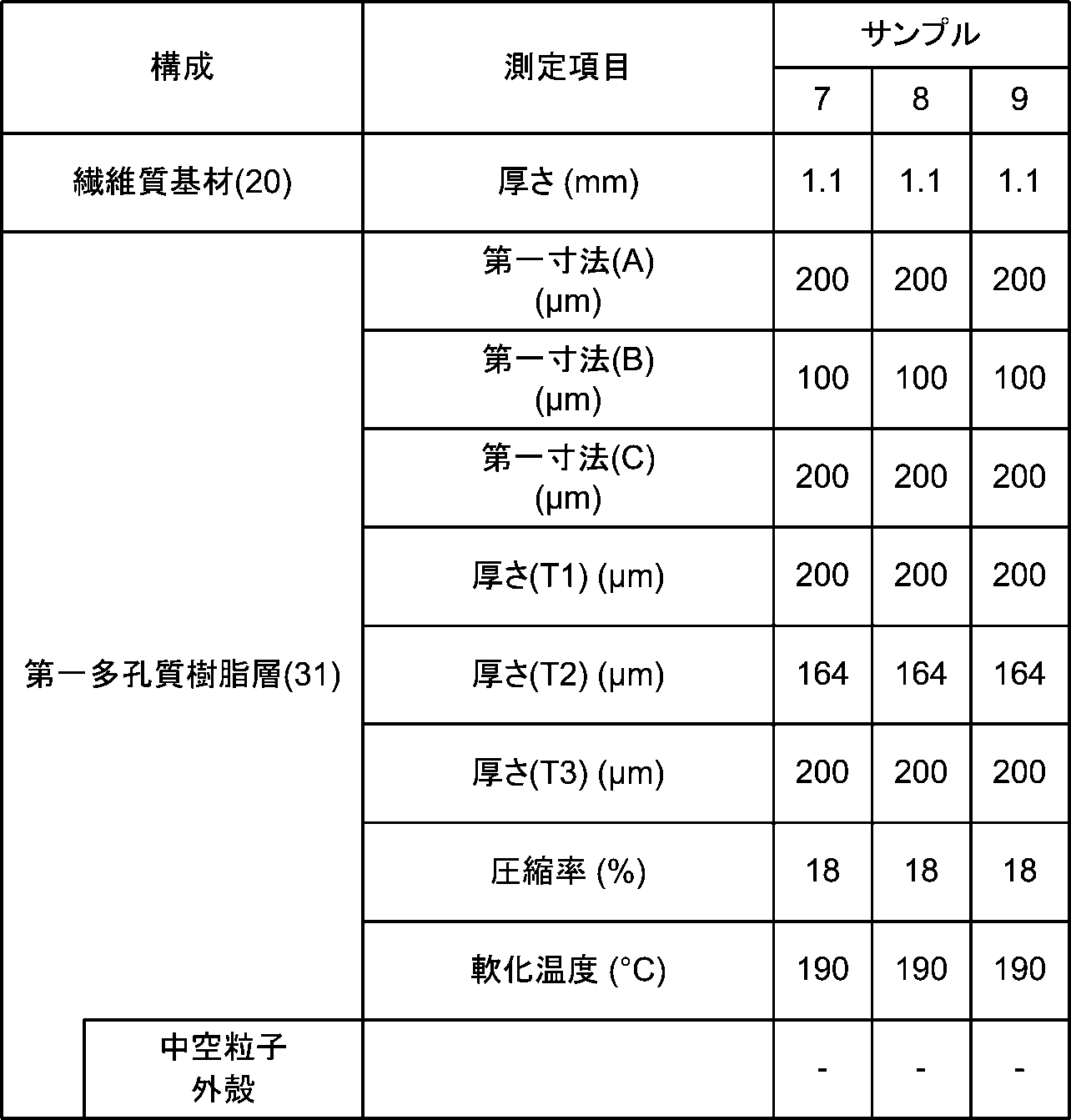


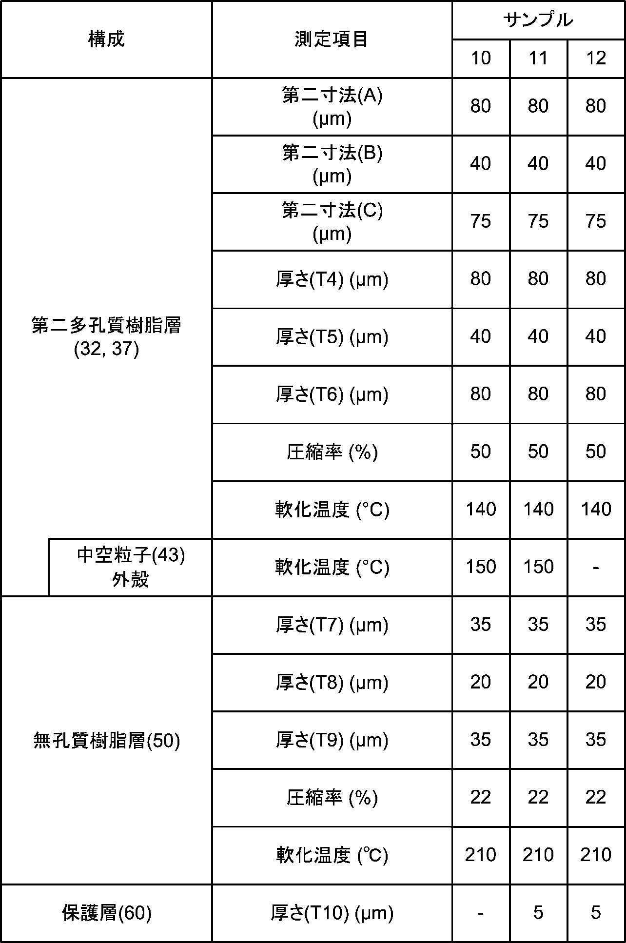
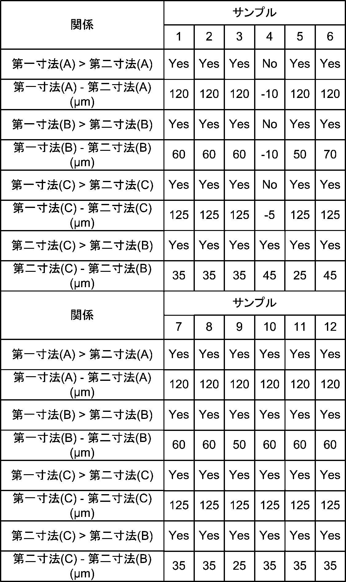
実施形態によれば、次のような効果を得ることができる。
実施形態は、次のようにすることもできる。以下に示す変形例のうちの幾つかの構成は、適宜組み合わせて採用することもできる。以下では、上記とは異なる点を説明することとし、同様の点についての説明は適宜省略する。
31 第一多孔質樹脂層、 32 第二多孔質樹脂層、 40 孔
41 第一孔、 42 第二孔、 43 中空粒子
50 無孔質樹脂層、 60 保護層、 70 表皮材
71 凹凸模様、 72 凹部、 73 凸部
80 エンボス加工装置、 81 エンボス加工型、 82 成形部
83 凸部、 84 凹部、 85 エンボス受型、 86 加熱器
87 供給装置、 88 回収装置、 P1,P2 部分
T1~T10,TA,TB 厚さ、 T11 合計厚さ、 ΔT 厚み差
Claims (6)
- 繊維質基材と、
前記繊維質基材上に積層され、複数の孔を有する、多孔質樹脂層と、を含み、
前記多孔質樹脂層は、前記多孔質樹脂層の母材となる樹脂に複数の中空粒子を含有し、
前記複数の中空粒子は、前記樹脂に分散し、
前記中空粒子は、内部に前記孔を有する、合成皮革。 - 前記多孔質樹脂層は、
前記繊維質基材上に積層される第一多孔質樹脂層と、
前記第一多孔質樹脂層上に積層される第二多孔質樹脂層と、を含み、
前記第一多孔質樹脂層は、前記複数の孔の一部である複数の第一孔を有し、
前記第二多孔質樹脂層は、前記複数の孔の一部である複数の第二孔を有し、
前記複数の中空粒子は、前記第二多孔質樹脂層の母材となる樹脂に分散し、
前記中空粒子は、内部に前記第二孔を有する、請求項1に記載の合成皮革。 - 前記第一孔は、第一寸法の長径を有する閉鎖空間であり、
前記第二孔は、前記第一寸法より小さな第二寸法の長径を有する閉鎖空間である、請求項2に記載の合成皮革。 - 前記第一多孔質樹脂層の軟化温度は、第一温度であり、
前記第二多孔質樹脂層の軟化温度は、前記第一温度より低い第二温度である、請求項2に記載の合成皮革。 - 前記第一多孔質樹脂層の軟化温度は、第一温度であり、
前記第二多孔質樹脂層の軟化温度は、前記第一温度より低い第二温度である、請求項3に記載の合成皮革。 - 請求項1から請求項5の何れか1項に記載の合成皮革を含み、
前記合成皮革は、表面に凹凸模様を有する、表皮材。
Priority Applications (5)
| Application Number | Priority Date | Filing Date | Title |
|---|---|---|---|
| US18/689,138 US20240376666A1 (en) | 2021-10-08 | 2022-10-03 | Synthetic Leather And Skin Material |
| MX2024003082A MX2024003082A (es) | 2021-10-08 | 2022-10-03 | Cuero sintetico y material de piel. |
| CN202280052537.5A CN117730180A (zh) | 2021-10-08 | 2022-10-03 | 合成皮革和表皮材 |
| EP22878465.8A EP4414499A4 (en) | 2021-10-08 | 2022-10-03 | SYNTHETIC LEATHER AND SKIN MATERIAL |
| JP2023552867A JP7723752B2 (ja) | 2021-10-08 | 2022-10-03 | 合成皮革及び表皮材 |
Applications Claiming Priority (2)
| Application Number | Priority Date | Filing Date | Title |
|---|---|---|---|
| JP2021166245 | 2021-10-08 | ||
| JP2021-166245 | 2021-10-08 |
Publications (1)
| Publication Number | Publication Date |
|---|---|
| WO2023058596A1 true WO2023058596A1 (ja) | 2023-04-13 |
Family
ID=85804261
Family Applications (1)
| Application Number | Title | Priority Date | Filing Date |
|---|---|---|---|
| PCT/JP2022/036937 Ceased WO2023058596A1 (ja) | 2021-10-08 | 2022-10-03 | 合成皮革及び表皮材 |
Country Status (6)
| Country | Link |
|---|---|
| US (1) | US20240376666A1 (ja) |
| EP (1) | EP4414499A4 (ja) |
| JP (1) | JP7723752B2 (ja) |
| CN (1) | CN117730180A (ja) |
| MX (1) | MX2024003082A (ja) |
| WO (1) | WO2023058596A1 (ja) |
Citations (8)
| Publication number | Priority date | Publication date | Assignee | Title |
|---|---|---|---|---|
| JPH0261181A (ja) | 1988-08-22 | 1990-03-01 | Kuraray Co Ltd | 皮革様シートおよびその製造法 |
| JPH02307987A (ja) * | 1989-05-18 | 1990-12-21 | Achilles Corp | 合成皮革及びその製造方法 |
| JPH06192966A (ja) * | 1992-12-25 | 1994-07-12 | Kanebo Ltd | 銀付人工皮革 |
| JP2003293270A (ja) | 2002-03-29 | 2003-10-15 | Kuraray Co Ltd | 皮革様シート |
| JP2015104848A (ja) | 2013-11-29 | 2015-06-08 | セーレン株式会社 | 表皮材 |
| JP2015123597A (ja) * | 2013-12-25 | 2015-07-06 | セーレン株式会社 | 表皮材 |
| JP2016147466A (ja) | 2015-02-13 | 2016-08-18 | セーレン株式会社 | 車両内装用表皮材 |
| KR20200131774A (ko) * | 2019-05-14 | 2020-11-24 | (주)엘지하우시스 | 인조가죽, 이로부터 제조된 크래쉬 패드 스킨 및 이의 제조방법 |
Family Cites Families (4)
| Publication number | Priority date | Publication date | Assignee | Title |
|---|---|---|---|---|
| PL1887128T3 (pl) * | 2006-08-09 | 2010-03-31 | Hornschuch Ag K | Sposób wytwarzania oddychającej wielowarstwowej skóry sztucznej oraz oddychająca wielowarstwowa skóra sztuczna |
| JP5398451B2 (ja) * | 2009-09-28 | 2014-01-29 | セーレン株式会社 | 合成皮革の製造方法 |
| JP2013076173A (ja) * | 2011-09-29 | 2013-04-25 | Seiren Co Ltd | 合成皮革 |
| JP2018053411A (ja) * | 2016-09-30 | 2018-04-05 | 共和レザー株式会社 | 合成皮革及合成皮革の製造方法 |
-
2022
- 2022-10-03 WO PCT/JP2022/036937 patent/WO2023058596A1/ja not_active Ceased
- 2022-10-03 EP EP22878465.8A patent/EP4414499A4/en active Pending
- 2022-10-03 MX MX2024003082A patent/MX2024003082A/es unknown
- 2022-10-03 US US18/689,138 patent/US20240376666A1/en active Pending
- 2022-10-03 JP JP2023552867A patent/JP7723752B2/ja active Active
- 2022-10-03 CN CN202280052537.5A patent/CN117730180A/zh active Pending
Patent Citations (8)
| Publication number | Priority date | Publication date | Assignee | Title |
|---|---|---|---|---|
| JPH0261181A (ja) | 1988-08-22 | 1990-03-01 | Kuraray Co Ltd | 皮革様シートおよびその製造法 |
| JPH02307987A (ja) * | 1989-05-18 | 1990-12-21 | Achilles Corp | 合成皮革及びその製造方法 |
| JPH06192966A (ja) * | 1992-12-25 | 1994-07-12 | Kanebo Ltd | 銀付人工皮革 |
| JP2003293270A (ja) | 2002-03-29 | 2003-10-15 | Kuraray Co Ltd | 皮革様シート |
| JP2015104848A (ja) | 2013-11-29 | 2015-06-08 | セーレン株式会社 | 表皮材 |
| JP2015123597A (ja) * | 2013-12-25 | 2015-07-06 | セーレン株式会社 | 表皮材 |
| JP2016147466A (ja) | 2015-02-13 | 2016-08-18 | セーレン株式会社 | 車両内装用表皮材 |
| KR20200131774A (ko) * | 2019-05-14 | 2020-11-24 | (주)엘지하우시스 | 인조가죽, 이로부터 제조된 크래쉬 패드 스킨 및 이의 제조방법 |
Non-Patent Citations (1)
| Title |
|---|
| See also references of EP4414499A4 |
Also Published As
| Publication number | Publication date |
|---|---|
| JP7723752B2 (ja) | 2025-08-14 |
| EP4414499A4 (en) | 2025-10-22 |
| JPWO2023058596A1 (ja) | 2023-04-13 |
| MX2024003082A (es) | 2024-03-27 |
| CN117730180A (zh) | 2024-03-19 |
| EP4414499A1 (en) | 2024-08-14 |
| US20240376666A1 (en) | 2024-11-14 |
Similar Documents
| Publication | Publication Date | Title |
|---|---|---|
| JP6289058B2 (ja) | 表皮材 | |
| JP5496389B2 (ja) | 表皮材 | |
| JP7507022B2 (ja) | 自動車内装材 | |
| CN103696272A (zh) | 合成皮革及其制造方法 | |
| JP7205028B2 (ja) | 合成樹脂表皮材及びその製造方法 | |
| US20170362750A1 (en) | Skin material and method of producing skin material | |
| TWI480444B (zh) | 絨革感塗佈織物及其製造方法 | |
| JP6555894B2 (ja) | 車両内装用表皮材 | |
| JP2025074110A (ja) | 合成樹脂表皮材 | |
| JP7089866B2 (ja) | 開口部を有するシート状物およびその製造方法 | |
| CN118401716A (zh) | 合成皮革 | |
| JP5940336B2 (ja) | 合成皮革の製造方法 | |
| JPWO2019155692A1 (ja) | 合成樹脂表皮材の製造方法 | |
| CN106554681B (zh) | 涂布用组合物及具有涂布层的片材及其制造方法 | |
| WO2023058596A1 (ja) | 合成皮革及び表皮材 | |
| JP5728293B2 (ja) | 合成樹脂表皮材の製造方法 | |
| TWI769259B (zh) | 粒面狀人工皮革及粒面狀人工皮革之製造方法 | |
| KR102761882B1 (ko) | 자동차 내장재 커버링용 인조가죽 제조방법 및 이로부터 제조된 인조가죽 | |
| JP7516017B2 (ja) | 三次元成形された形状を有する接着フィルム | |
| KR102733358B1 (ko) | 자동차 내장재 커버링용 인조가죽 및 이의 제조방법 | |
| JP7303042B2 (ja) | 合成皮革 | |
| JP7699510B2 (ja) | 積層発泡シート、積層成形体、及びそれらの製造方法 | |
| JP2019077961A (ja) | 合成皮革 | |
| JP5236896B2 (ja) | 樹脂成形品の製造方法 | |
| JP2007046183A (ja) | 皮革様シート状物、その製造方法ならびにそれを用いてなる内装材および衣料資材。 |
Legal Events
| Date | Code | Title | Description |
|---|---|---|---|
| 121 | Ep: the epo has been informed by wipo that ep was designated in this application |
Ref document number: 22878465 Country of ref document: EP Kind code of ref document: A1 |
|
| WWE | Wipo information: entry into national phase |
Ref document number: 202280052537.5 Country of ref document: CN |
|
| WWE | Wipo information: entry into national phase |
Ref document number: 2023552867 Country of ref document: JP |
|
| WWE | Wipo information: entry into national phase |
Ref document number: 18689138 Country of ref document: US |
|
| WWE | Wipo information: entry into national phase |
Ref document number: 2401001865 Country of ref document: TH |
|
| WWE | Wipo information: entry into national phase |
Ref document number: 202447027545 Country of ref document: IN |
|
| WWE | Wipo information: entry into national phase |
Ref document number: 2022878465 Country of ref document: EP |
|
| NENP | Non-entry into the national phase |
Ref country code: DE |
|
| ENP | Entry into the national phase |
Ref document number: 2022878465 Country of ref document: EP Effective date: 20240508 |