WO2023063031A1 - 帯鋸刃及び帯鋸刃の製造方法 - Google Patents
帯鋸刃及び帯鋸刃の製造方法 Download PDFInfo
- Publication number
- WO2023063031A1 WO2023063031A1 PCT/JP2022/034997 JP2022034997W WO2023063031A1 WO 2023063031 A1 WO2023063031 A1 WO 2023063031A1 JP 2022034997 W JP2022034997 W JP 2022034997W WO 2023063031 A1 WO2023063031 A1 WO 2023063031A1
- Authority
- WO
- WIPO (PCT)
- Prior art keywords
- teeth
- tooth
- band saw
- saw blade
- coat layer
- Prior art date
- Legal status (The legal status is an assumption and is not a legal conclusion. Google has not performed a legal analysis and makes no representation as to the accuracy of the status listed.)
- Ceased
Links
Images


Classifications
-
- B—PERFORMING OPERATIONS; TRANSPORTING
- B23—MACHINE TOOLS; METAL-WORKING NOT OTHERWISE PROVIDED FOR
- B23D—PLANING; SLOTTING; SHEARING; BROACHING; SAWING; FILING; SCRAPING; LIKE OPERATIONS FOR WORKING METAL BY REMOVING MATERIAL, NOT OTHERWISE PROVIDED FOR
- B23D61/00—Tools for sawing machines or sawing devices; Clamping devices for these tools
- B23D61/12—Straight saw blades; Strap saw blades
- B23D61/127—Straight saw blades; Strap saw blades of special material
-
- B—PERFORMING OPERATIONS; TRANSPORTING
- B23—MACHINE TOOLS; METAL-WORKING NOT OTHERWISE PROVIDED FOR
- B23D—PLANING; SLOTTING; SHEARING; BROACHING; SAWING; FILING; SCRAPING; LIKE OPERATIONS FOR WORKING METAL BY REMOVING MATERIAL, NOT OTHERWISE PROVIDED FOR
- B23D61/00—Tools for sawing machines or sawing devices; Clamping devices for these tools
- B23D61/12—Straight saw blades; Strap saw blades
-
- B—PERFORMING OPERATIONS; TRANSPORTING
- B23—MACHINE TOOLS; METAL-WORKING NOT OTHERWISE PROVIDED FOR
- B23D—PLANING; SLOTTING; SHEARING; BROACHING; SAWING; FILING; SCRAPING; LIKE OPERATIONS FOR WORKING METAL BY REMOVING MATERIAL, NOT OTHERWISE PROVIDED FOR
- B23D65/00—Making tools for sawing machines or sawing devices for use in cutting any kind of material
Definitions
- the present disclosure relates to band saw blades and methods of manufacturing band saw blades.
- Patent Document 1 describes a method of winding the band saw blade into a spiral coil and coating it in a coating device in order to coat the teeth of the band saw blade with a hard material.
- Patent Document 1 is a common band saw blade coating method, and is performed at the final stage of the band saw blade manufacturing process.
- a band-shaped spacer is overlapped and wound together with the band saw blade in order to form a gap between radially adjacent tooth rows. By forming this gap, the tooth row can be coated well.
- One aspect of the present disclosure is a band-shaped endless trunk, a tooth portion in which a set of a predetermined number of teeth including set teeth is repeatedly formed on one edge side of the trunk, and the tooth portion and a coat layer formed on the surface of the teeth, wherein the set tooth has a first indentation portion as a concave portion in the coat layer on the outer surface in the swing direction, and in the concave portion of the first indentation portion In the band saw blade, the thickness of the coat layer is thinner than the thickness of the portion of the coat layer other than the concave portion.
- the coat layer was formed before the set teeth were swung out, and the set teeth do not have unevenness in the thickness of the coat layer.
- One aspect of the present disclosure is a band-shaped endless trunk, a tooth portion in which a set of a predetermined number of teeth including set teeth is repeatedly formed on one edge side of the trunk, and the tooth portion and a coating layer formed on the surface of the tooth of the band saw blade, wherein the coating layer is formed on the teeth of an intermediate blade whose teeth are all straight teeth.
- a setting process is performed to set the teeth by setting the predetermined teeth.
- the set teeth do not have unevenness in the thickness of the coat layer.
- the teeth of the band saw blade, particularly the set teeth have no coating layer thickness unevenness.
- FIG. 1A is a two-sided view showing a side surface and an upper surface of a first intermediate blade 1A used for manufacturing the band saw blade 1 according to this embodiment.
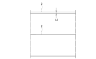
- FIG. 1B is a two-sided view showing a side surface and an upper surface of the spacer 2 used for manufacturing the band saw blade 1 according to this embodiment.
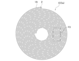
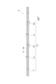
- FIG. 2 is a plan view showing a coil body C in which the first intermediate blade 1A and the spacer 2 are stacked and wound.
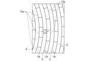
- FIG. 3 is an enlarged view of the F3 area in FIG.
- FIG. 4 is a schematic diagram for explaining the coating process of the coil body C by the coating device 7.
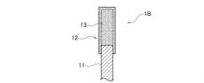
- FIG. 5 is a side view showing the second intermediate blade 1B in which the coating layer 13 is formed on the teeth 12.
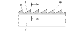
- FIG. 6 is a cross-sectional view taken along line S6-S6 in FIG.
- FIG. 7A is a diagram for explaining the swaging process for the second intermediate blade 1B, and is a cross-sectional view showing a state immediately before the process.
- FIG. 7B is a diagram for explaining the swinging process for the second intermediate blade 1B, and is a cross-sectional view showing a state during processing.
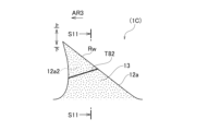
- FIG. 8 is a top view showing a third intermediate blade 1C that has been subjected to a flinging process with respect to the second intermediate blade 1B.
- FIG. 9 is a diagram for explaining the joining step of joining the third intermediate blade 1C in a loop to form the band saw blade 1. As shown in FIG. FIG. FIG.
- FIG. 10A is a right side view showing the surface condition of the main portion of the teeth 12a of the band saw blade 1.
- FIG. 10B is a left side view showing the surface condition of teeth 12a of band saw blade 1.
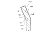
- FIG. 11A is a cross-sectional view showing a cross-section of teeth 12a in band saw blade 1.
- FIG. 11B is an enlarged view of the indentation portion T81 in FIG. 11A.
- FIG. 11C is an enlarged view of the indentation portion T82 in FIG. 11A.
- FIG. 12A is a right side view showing the surface condition of teeth 112a in band saw blade 101 of a comparative example.
- FIG. 12B is a left side view showing the surface state of teeth 112a in band saw blade 101 of the comparative example.
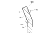
- FIG. 13A is a sectional view showing a section of tooth 112a in band saw blade 101 of a comparative example.
- FIG. 13B is an enlarged view of the indentation portion T181 in FIG. 13A.
- FIG. 13C is an enlarged view of the indentation portion T182 in FIG. 13A.
- FIG. 1A is a two-sided view showing a side surface and an upper surface of the first intermediate blade 1A used for manufacturing the band saw blade 1 according to this embodiment.
- FIG. 1B is a two-sided view showing a side surface and an upper surface of the spacer 2 used for manufacturing the band saw blade 1 according to this embodiment.
- the band saw blade 1 is made of a long band-shaped first intermediate blade 1A, and passes through a second intermediate blade 1B and a third intermediate blade 1C, which are intermediate bodies obtained as the manufacturing process progresses, and then a third intermediate blade 1C of a predetermined length. It is formed by joining endlessly cut pieces.
- FIG. 2 is a plan view showing a coil body C in which the first intermediate blade 1A and the spacer 2 are wound together.
- FIG. 3 is an enlarged view of the F3 area in FIG.
- FIG. 4 is a schematic diagram for explaining the coating process of the coil body C by the coating device 7.
- FIG. 5 is a side view showing the second intermediate blade 1B in which the coating layer 13 is formed on the teeth 12.
- FIG. 6 is a cross-sectional view taken along line S6-S6 in FIG. FIG.
- FIG. 7A is a diagram for explaining the swaging process for the second intermediate blade 1B, and is a cross-sectional view showing a state immediately before the process.
- FIG. 7B is a diagram for explaining the swinging process for the second intermediate blade 1B, and is a cross-sectional view showing a state during processing.
- FIG. 8 is a top view showing a third intermediate blade 1C that has been subjected to a flinging process with respect to the second intermediate blade 1B.
- 9A and 9B are diagrams for explaining the joining process of forming the band saw blade 1 by joining the third intermediate blade 1C endlessly.
- a first intermediate blade 1A having a predetermined length as a material and a spacer 2 having the same length as the first intermediate blade 1A as a manufacturing jig are prepared.
- the first intermediate blade 1A has, as shown in FIG. 1A, a long belt-like trunk portion 11 and a tooth portion 12 formed on one edge side (upper edge side) of the trunk portion 11.
- the tooth portion 12 has a plurality of teeth 12a formed continuously in the longitudinal direction of the body portion 11 .
- This tooth 12a is a straight tooth.
- the spacer 2 is a long strip-shaped member made of metal.
- the width of the spacer 2 is slightly smaller than the width of the body 11 of the first intermediate blade 1A, and the thickness is indicated as thickness L2.
- the first intermediate blade 1A and the spacer 2 are overlapped with the edges on the opposite side of the teeth 12 aligned, and lap-wound in a spiral coil to form a coil body C.
- the first intermediate blade 1A is indicated by a solid line and the spacer 2 is indicated by a dashed line.
- the coil body C is lap-wound in a spiral coil shape with a spacer 2 interposed between the radially adjacent first intermediate blades 1A. Since the teeth 12a of the first intermediate blade 1A are all straight teeth, the minimum gap La between the radially adjacent first intermediate blades 1A is the gap between the body portions 11 and the thickness of the spacer 2 is L2.
- this coil body C is put into the coating device 7 to be coated.
- the coil body C before coating is referred to as pre-coating coil body Ca
- the coil body C after coating is referred to as post-processing coil body Cb.
- the method of coating treatment is a PVD (Physical Vapor Deposition) method, but is not limited to this, and may be a CVD (Chemical Vapor Deposition) method, for example.
- At least the range of the first intermediate blade 1A to be coated is the surface of the tooth portion 12, which is the portion of the pre-processed coil body Ca that is not in contact with the spacer 2. As shown in FIG.
- a difference occurs in the thickness of the deposited layer between the shadowed portion and the non-shadowed portion, resulting in unevenness.
- the coiled body Cb After performing the coating treatment under predetermined conditions, the coiled body Cb is taken out and unwound after the treatment.
- the second intermediate blade 1B in which the coating treatment is applied to the teeth 12 of the first intermediate blade 1A is obtained from the coiled body Cb after the treatment.
- the second intermediate blade 1B is coated so that the spacer 2 is not in contact with the tooth 12 and the edge of the body 11 on the tooth 12 side.
- a coat layer 13 (dotted portion) is formed.
- the coating layer 13 may be, for example, a layer of titanium nitride (TiN), titanium aluminum nitride (TiAlN), titanium carbon nitride (TiCN), or chromium nitride (CrN). or a combination thereof.
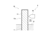
- a setting machine 8 is used to swing predetermined teeth out of the plurality of straight teeth 12a of the second intermediate blade 1B to the left or right to form set teeth.
- the clam remover 8 includes a fixed portion 81 that supports the second intermediate blade 1B in the thickness direction, and a portion that locally hits the side surface of the tooth 12a in the thickness direction indicated by the arrow DR1. It has a working part 82 that pushes to.
- the fixing part 81 of the short-necked shelling machine 8 sandwiches and fixes the trunk part 11 so that the tooth part 12 of the second intermediate blade 1B protrudes from the fixing part 81 and is exposed.
- the processing unit 82 pushes one side of the tooth 12a in the thickness direction, bends the tooth 12a to the other side as indicated by the arrow DR2, and swings it out.
- Predetermined teeth of the second intermediate blade 1B are swung either leftward or rightward by the setting machine 8 to obtain the third intermediate blade 1C shown in FIG.
- the tooth portion 12 of the third intermediate blade 1C is configured such that a set of five teeth formed continuously constitutes one tooth row TG, and this tooth row TG is repeatedly formed in the longitudinal direction.
- a tooth row TG shown in FIG. 8 is a set of a predetermined number of teeth including set teeth.
- the tooth row TG is a set of five teeth: a right set tooth Rw, a left set tooth Ln, a right set tooth Rn, a left set tooth Lw, and a straight tooth S from the cutting direction (arrow DR3) side. is.
- the swing-out amounts of the left set tooth Lw and the right set tooth Rw are larger than the swing-out amounts of the left set tooth Ln and the right set tooth Rn.
- the configuration of the tooth row TG is not limited to that shown in FIG.
- both ends of the body portion 11 of the third intermediate blade 1C are welded together at the joint Pm where the ends of the body portion 11 of the third intermediate blade 1C abut each other. As a result, a belt-like endless band saw blade 1 is obtained.
- the spacer 2 lap-wound with the coil body C may have a thickness of L2.
- the thickness of the coating layer differs between the inner surface that is a shadow in the launch direction and the outer surface that is the front in the launch direction, resulting in unevenness. no. That is, according to the manufacturing method of the band saw blade 1, the thickness of the coating layer 13 becomes uniform in the coating range.
- the band saw blade 1 is manufactured by forming the coat layer 13 on the surfaces of the teeth 12a and then performing the flinging process. Therefore, in the fluffing process, the fixed part 81 and the processed part 82 of the short-necked shelling machine 8 are pressed from above the coat layer 13, so that the edges of the processed part 82 and the fixed part 81 form a characteristic indentation different from the conventional one. be done.
- the indentation portion will be described with reference to FIGS. 10A, 10B, 11A, 11B, and 11C, taking the right set tooth Rw swung to the right as an example.
- FIG. 10A is a right side view showing the surface condition of teeth 12a of band saw blade 1
- FIG. 10B is a left side view showing the surface condition of teeth 12a of band saw blade 1.
- FIG. 11A is a cross-sectional view showing a cross-section of teeth 12a in band saw blade 1.
- FIG. 11B is an enlarged view of the indentation portion T81 in FIG. 11A
- FIG. 11C is an enlarged view of the indentation portion T82 in FIG. 11A.
- an indentation portion T81 (second indentation portion) by the fixing portion 81 is formed at the root portion of the right side surface, which is the inner surface 12a1 of the tooth 12a of the right set tooth Rw in the swing-out direction. T81) is formed.
- the indentation portion T81 is clearly visible along the entire longitudinal direction of the tooth 12a in a straight line extending in the longitudinal direction of the body portion 11. As shown in FIG. As shown in FIGS.
- the indentation portion T81, the indentation portion T82, and the coat layer 13 are subjected to a swirling process for performing a swirling process after the coat layer forming process of forming the coat layer 13 on the teeth 12a.
- the following features (A), (B), and (C) arise.
- the fixed portion 81 forms the bent portion 12c.
- the coat layer 13 is peeled off due to friction with the fixed portion 81 in the region on the surface of the tooth 12a from the bent portion 12c to the trunk portion 11 side, and the formation density of the coat layer 13 is low.
- the coat layer 13 has different formation densities on the tip side and on the trunk side with the indentation portion T81 as a boundary. Due to this and the pressing of the processed portion 82 against the coating layer 13, the indentation portion T81 formed on the surface of the tooth 12a is clearly visible.
- the recessed portion 12b is formed by the processing portion 82 . Therefore, the coat layer 13b of the concave portion 12b is compressed and made smaller (thinner) than the other portions of the coat layer 13 (portions other than the concave portions).
- the recessed portion 12b is formed by the processing portion 82 . Therefore, a clearly visible indentation portion T82 is formed on the surface of the coat layer 13 .
- FIGS. 12A, 12B, 13A, 13B and 13C the indentations T181 and T182 formed on the band saw blade 101 of the comparative example are as shown in FIGS. 12A, 12B, 13A, 13B and 13C.
- the band saw blade 101 of this comparative example is manufactured by a conventional manufacturing method of coating after forming set teeth.
- FIG. 12A is a right side view showing the surface state of teeth 112a of band saw blade 101 of the comparative example
- FIG. 12B is a left side view showing the surface state of teeth 112a of band saw blade 101 of the comparative example.
- 13A is a cross-sectional view showing a cross section of tooth 112a in band saw blade 101 of a comparative example
- FIG. 13B is an enlarged view of indentation portion T181 in FIG. 13A
- FIG. 13C is an enlarged view of indentation portion T182 in FIG. 13A. It is a diagram.
- an indentation portion T181 is formed by the fixing portion 81 at the root portion of the right side surface of the tooth 112a of the right set tooth Rw.
- the indentation portion T181 is linearly extending in the longitudinal direction of the trunk portion 11, and is slightly thin and can be visually recognized as part of the teeth 112a in some cases.
- an indentation portion T182 by the processing portion 82 is formed at the center portion in the tooth height direction (vertical direction) of the left side surface of the tooth 112a of the right set tooth Rw. there is The indentation portion T182 is linearly inclined so that the cutting direction AR3 side faces downward, is slightly thin, and can be visually recognized as part of the tooth 112a in some cases.
- the coat layer 113 is formed so as to cover the bent portion 112c and the recessed portion 112b. Therefore, the bent portion 112c and the recessed portion 112b are hidden by the coat layer 113, and the indentation portions T181 and T182 may be partially difficult or invisible.
- the band saw blade 1 of the embodiment has a characteristic configuration different from that of the conventional product, even in the manufactured product itself, by performing the flinging process after forming the coat layer 13. That is, features (A), (B), and (C) of the band saw blade 1 are differences corresponding to features (D), (E), and (F) of the band saw blade 101 of the comparative example, respectively. As a characteristic configuration unique to the band saw blade 1, the band saw blade 1 can be distinguished from other band saw blades.
- the band saw blade 1 of the present embodiment has a band-shaped endless trunk portion 11 and a tooth row TG which is a set of a predetermined number of teeth 12a including set teeth Rw on one edge side of the trunk portion 11.
- the teeth 12 are formed repeatedly, and the coat layer 13 is formed on the surface of the teeth 12a of the teeth 12.
- the set teeth Rw are provided as recesses 12b in the coat layer 13 of the outer surface 12a2 in the swing direction. It has one indentation portion T82, and the thickness of the coat layer 13 in the concave portion 12b of the first indentation portion T82 is thinner than the thickness of the portion of the coat layer 13 other than the concave portion 12b.
- the band saw blade 1 further has a second indentation portion T81 as a bent portion 12c on the outer surface of the coat layer 13 of the inner surface 12a1 in the swing direction of the set teeth Rw.
- the formation density on the side of the trunk portion 11 may be lower than on the side of the tip of the tooth.
- the band saw blade 1 having these characteristics has a coating layer 13 of uniform thickness formed in the parts required for cutting by the coating process in the manufacturing process.
- the band saw blade manufacturing method of the present embodiment uses a band-shaped looped trunk portion 11 and a set of a predetermined number of teeth 12a including set teeth Rw on one edge side of the trunk portion 11.
- the predetermined teeth 12a are swung out to form set teeth Rw.
- the coating process which is the coating layer forming process, is performed only on the straight teeth. Thereby, a coat layer having a uniform thickness can be formed.
- the coating layer forming step further includes winding the intermediate blade 1A and the band-shaped spacer 2 so that the teeth 12 are exposed, thereby forming the spiral coil-shaped coil body C. Then, the formed coil body C is put into the coating device 7 to form the coating layer 13 .
- the configuration of the set teeth and straight teeth of the tooth row TG of the band saw blade 1 is not limited.
- the material and formation method of the coat layer 13 are not limited.
- the thickness of the spacer 2 may be set as thin as possible within the range in which a good coating layer 13 can be obtained depending on the type of band saw blade 1 and the conditions of the coating process. As a result, the length of the saw blade that can form the coat layer in one coating process can be made longer.
Landscapes
- Engineering & Computer Science (AREA)
- Mechanical Engineering (AREA)
- Bending Of Plates, Rods, And Pipes (AREA)
Abstract
Description
Claims (4)
- 帯状で無端状の胴部と、
前記胴部の一縁側に、アサリ歯を含む所定数の歯の組である歯列が繰り返し形成された歯部と、
前記歯部の前記歯の表面に形成されたコート層と、を備え、
前記アサリ歯は、振り出し方向の外面の前記コート層に凹部としての第1圧痕部を有し、
前記第1圧痕部の前記凹部における前記コート層の厚さは、前記コート層の前記凹部以外の部分の厚さよりも薄い帯鋸刃。 - 前記アサリ歯は、振り出し方向の内面の前記コート層に屈曲部としての第2圧痕部を有し、
前記コート層は、前記第2圧痕部を境界として歯先側よりも前記胴部側の形成密度が低い請求項1記載の帯鋸刃。 - 帯状で無端状の胴部と、前記胴部の一縁側に、アサリ歯を含む所定数の歯の組である歯列が繰り返し形成された歯部と、前記歯部の前記歯の表面に形成されたコート層と、を備えた帯鋸刃の製造方法であって、
前記歯がすべて直歯である中間ブレードの前記歯に対して前記コート層を形成するコート層形成工程を実行した後に、所定の前記歯を振り出して前記アサリ歯にする振り出し加工を実行する帯鋸刃の製造方法。 - 前記コート層形成工程は、前記中間ブレードと帯状のスペーサとを前記歯部が露出するよう重ね巻きして渦巻コイル状のコイル体を形成し、形成した前記コイル体をコーティング装置に投入してコート層を形成する請求項3記載の帯鋸刃の製造方法。
Priority Applications (3)
| Application Number | Priority Date | Filing Date | Title |
|---|---|---|---|
| US18/698,842 US20240316663A1 (en) | 2021-10-14 | 2022-09-20 | Band saw blade and method for manufacturing band saw blade |
| EP22880727.7A EP4417352B1 (en) | 2021-10-14 | 2022-09-20 | Band saw blade and manufacturing method for band saw blade |
| CN202280068944.5A CN118103164A (zh) | 2021-10-14 | 2022-09-20 | 带锯条以及带锯条的制造方法 |
Applications Claiming Priority (2)
| Application Number | Priority Date | Filing Date | Title |
|---|---|---|---|
| JP2021-168801 | 2021-10-14 | ||
| JP2021168801A JP7728141B2 (ja) | 2021-10-14 | 2021-10-14 | 帯鋸刃及び帯鋸刃の製造方法 |
Publications (1)
| Publication Number | Publication Date |
|---|---|
| WO2023063031A1 true WO2023063031A1 (ja) | 2023-04-20 |
Family
ID=85987678
Family Applications (1)
| Application Number | Title | Priority Date | Filing Date |
|---|---|---|---|
| PCT/JP2022/034997 Ceased WO2023063031A1 (ja) | 2021-10-14 | 2022-09-20 | 帯鋸刃及び帯鋸刃の製造方法 |
Country Status (5)
| Country | Link |
|---|---|
| US (1) | US20240316663A1 (ja) |
| EP (1) | EP4417352B1 (ja) |
| JP (1) | JP7728141B2 (ja) |
| CN (1) | CN118103164A (ja) |
| WO (1) | WO2023063031A1 (ja) |
Citations (7)
| Publication number | Priority date | Publication date | Assignee | Title |
|---|---|---|---|---|
| JPS5453383A (en) * | 1977-10-05 | 1979-04-26 | Fuji Seikiyo Kk | Method of working hand saw |
| JPH07116917A (ja) * | 1993-10-27 | 1995-05-09 | Romatec Kk | 機械鋸の刃先強化処理装置 |
| JP2007061957A (ja) * | 2005-08-31 | 2007-03-15 | Nachi Fujikoshi Corp | 帯鋸刃 |
| JP2010280022A (ja) * | 2009-06-03 | 2010-12-16 | Amada Co Ltd | 帯鋸刃及びその製造方法 |
| JP5174467B2 (ja) | 2005-02-24 | 2013-04-03 | エリコン トレーディング アーゲー.,トリュープバッハ | 帯鋸及び帯鋸の製造方法 |
| JP2017064898A (ja) * | 2015-07-15 | 2017-04-06 | シーフォー・カーバイズ・リミテッドC4 Carbides Limited | 工具刃、工具刃の製造方法、およびコンピュータ読取可能な媒体 |
| JP2021168801A (ja) | 2020-04-15 | 2021-10-28 | 株式会社三洋物産 | 遊技機 |
Family Cites Families (9)
| Publication number | Priority date | Publication date | Assignee | Title |
|---|---|---|---|---|
| US3615309A (en) * | 1968-02-08 | 1971-10-26 | Remington Arms Co Inc | Armored metal tools |
| US3988955A (en) * | 1972-12-14 | 1976-11-02 | Engel Niels N | Coated steel product and process of producing the same |
| JPH0430908A (ja) * | 1990-05-25 | 1992-02-03 | Toyo Tokushu Kinzoku Kogyo Kk | 鋸歯 |
| CN1106900C (zh) * | 1997-05-08 | 2003-04-30 | 阿曼德有限公司 | 用于由多个锯齿连续切割工件的带锯条 |
| SE518755C2 (sv) * | 2001-02-19 | 2002-11-19 | Kapman Ab | Skränkanordning för sågblad |
| JP3710435B2 (ja) * | 2002-06-25 | 2005-10-26 | 辰夫 下古谷 | 帯鋸と帯鋸の加工装置および帯鋸の製造方法 |
| US20060213342A1 (en) * | 2005-03-22 | 2006-09-28 | Fisher-Barton Llc | Wear resistant cutting blade |
| JP5173670B2 (ja) * | 2008-08-20 | 2013-04-03 | 株式会社アマダ | 鋸刃及びその製造方法 |
| US20140150620A1 (en) * | 2012-11-30 | 2014-06-05 | Irwin Industrial Tool Company | Saw Blade Having Different Material Teeth and Method of Manufacture |
-
2021
- 2021-10-14 JP JP2021168801A patent/JP7728141B2/ja active Active
-
2022
- 2022-09-20 US US18/698,842 patent/US20240316663A1/en active Pending
- 2022-09-20 EP EP22880727.7A patent/EP4417352B1/en active Active
- 2022-09-20 CN CN202280068944.5A patent/CN118103164A/zh active Pending
- 2022-09-20 WO PCT/JP2022/034997 patent/WO2023063031A1/ja not_active Ceased
Patent Citations (7)
| Publication number | Priority date | Publication date | Assignee | Title |
|---|---|---|---|---|
| JPS5453383A (en) * | 1977-10-05 | 1979-04-26 | Fuji Seikiyo Kk | Method of working hand saw |
| JPH07116917A (ja) * | 1993-10-27 | 1995-05-09 | Romatec Kk | 機械鋸の刃先強化処理装置 |
| JP5174467B2 (ja) | 2005-02-24 | 2013-04-03 | エリコン トレーディング アーゲー.,トリュープバッハ | 帯鋸及び帯鋸の製造方法 |
| JP2007061957A (ja) * | 2005-08-31 | 2007-03-15 | Nachi Fujikoshi Corp | 帯鋸刃 |
| JP2010280022A (ja) * | 2009-06-03 | 2010-12-16 | Amada Co Ltd | 帯鋸刃及びその製造方法 |
| JP2017064898A (ja) * | 2015-07-15 | 2017-04-06 | シーフォー・カーバイズ・リミテッドC4 Carbides Limited | 工具刃、工具刃の製造方法、およびコンピュータ読取可能な媒体 |
| JP2021168801A (ja) | 2020-04-15 | 2021-10-28 | 株式会社三洋物産 | 遊技機 |
Non-Patent Citations (1)
| Title |
|---|
| See also references of EP4417352A4 |
Also Published As
| Publication number | Publication date |
|---|---|
| CN118103164A (zh) | 2024-05-28 |
| EP4417352A1 (en) | 2024-08-21 |
| JP2023058962A (ja) | 2023-04-26 |
| US20240316663A1 (en) | 2024-09-26 |
| EP4417352B1 (en) | 2025-10-29 |
| JP7728141B2 (ja) | 2025-08-22 |
| EP4417352A4 (en) | 2025-03-12 |
Similar Documents
| Publication | Publication Date | Title |
|---|---|---|
| CA2539345C (en) | Multi-chip facet cutting saw blade and related method | |
| EP3986654B1 (en) | Saw blade having thin film ceramic coating | |
| JPH11245282A5 (ja) | ||
| WO2016063893A1 (ja) | ドリルおよびそれを用いた切削加工物の製造方法 | |
| WO2023063031A1 (ja) | 帯鋸刃及び帯鋸刃の製造方法 | |
| US4816097A (en) | Method of manufacturing a non-metallic core having a perforated septum embedded therein | |
| JPH02107806A (ja) | 層材料からなるスラスト滑り軸受及びその製作方法 | |
| EP3442741B1 (fr) | Noyau de conformation à chaud d'une pièce métallique et procédé de fabrication | |
| JP2004243492A (ja) | シングルワイヤソー用ソーワイヤ | |
| JP3196510B2 (ja) | 硬質蒸着層がすぐれた耐剥離性を有する表面被覆炭化タングステン基超硬合金製エンドミル | |
| KR102862332B1 (ko) | 절단 공구의 치형부들을 코팅하기 위한 방법 | |
| EP1591184B1 (en) | Method to make a tool for working wood or similar materials | |
| JPH04310325A (ja) | 硬質膜被覆高速度鋼切削工具の製造方法 | |
| JP4188604B2 (ja) | 帯鋸刃 | |
| JP3191238B2 (ja) | フィンガカッタ | |
| TW202519383A (zh) | 切斷裝置、切斷方法及多層材 | |
| JP2003028299A (ja) | スペーサーエキスパンダおよびその製造方法 | |
| KR20250092907A (ko) | 도금강판 및 그 제조 방법 | |
| JP6657542B2 (ja) | 切削工具 | |
| KR102340692B1 (ko) | 특히 표면 지형을 갖는 시계학을 위한 구성요소 및 상기 구성요소를 제조하기 위한 방법 | |
| JPH08174309A (ja) | 硬質膜被覆切削工具および硬質膜被覆切削工具の製造方法 | |
| JP3790949B2 (ja) | 円盤状工具 | |
| WO2026027830A1 (fr) | Procédé de fabrication d'une pièce par machine de fabrication additive par fusion sur lit de poudre | |
| FR2712016A1 (fr) | Procédé de fabrication de parois de coffrage pour bâtiment et chaîne de fabrication s'y rapportant. | |
| WO2023181106A1 (ja) | ダイヤモンド被覆体 |
Legal Events
| Date | Code | Title | Description |
|---|---|---|---|
| 121 | Ep: the epo has been informed by wipo that ep was designated in this application |
Ref document number: 22880727 Country of ref document: EP Kind code of ref document: A1 |
|
| WWE | Wipo information: entry into national phase |
Ref document number: 18698842 Country of ref document: US |
|
| WWE | Wipo information: entry into national phase |
Ref document number: 202280068944.5 Country of ref document: CN |
|
| WWE | Wipo information: entry into national phase |
Ref document number: 2022880727 Country of ref document: EP |
|
| NENP | Non-entry into the national phase |
Ref country code: DE |
|
| ENP | Entry into the national phase |
Ref document number: 2022880727 Country of ref document: EP Effective date: 20240514 |
|
| WWG | Wipo information: grant in national office |
Ref document number: 2022880727 Country of ref document: EP |