WO2023074733A1 - 炭素繊維強化複合材料 - Google Patents
炭素繊維強化複合材料 Download PDFInfo
- Publication number
- WO2023074733A1 WO2023074733A1 PCT/JP2022/039900 JP2022039900W WO2023074733A1 WO 2023074733 A1 WO2023074733 A1 WO 2023074733A1 JP 2022039900 W JP2022039900 W JP 2022039900W WO 2023074733 A1 WO2023074733 A1 WO 2023074733A1
- Authority
- WO
- WIPO (PCT)
- Prior art keywords
- layer
- vcf
- particles
- carbon fiber
- cfrp
- Prior art date
- Legal status (The legal status is an assumption and is not a legal conclusion. Google has not performed a legal analysis and makes no representation as to the accuracy of the status listed.)
- Ceased
Links
Images







Classifications
-
- C—CHEMISTRY; METALLURGY
- C08—ORGANIC MACROMOLECULAR COMPOUNDS; THEIR PREPARATION OR CHEMICAL WORKING-UP; COMPOSITIONS BASED THEREON
- C08J—WORKING-UP; GENERAL PROCESSES OF COMPOUNDING; AFTER-TREATMENT NOT COVERED BY SUBCLASSES C08B, C08C, C08F, C08G or C08H
- C08J5/00—Manufacture of articles or shaped materials containing macromolecular substances
- C08J5/24—Impregnating materials with prepolymers which can be polymerised in situ, e.g. manufacture of prepregs
- C08J5/241—Impregnating materials with prepolymers which can be polymerised in situ, e.g. manufacture of prepregs using inorganic fibres
- C08J5/243—Impregnating materials with prepolymers which can be polymerised in situ, e.g. manufacture of prepregs using inorganic fibres using carbon fibres
-
- B—PERFORMING OPERATIONS; TRANSPORTING
- B32—LAYERED PRODUCTS
- B32B—LAYERED PRODUCTS, i.e. PRODUCTS BUILT-UP OF STRATA OF FLAT OR NON-FLAT, e.g. CELLULAR OR HONEYCOMB, FORM
- B32B1/00—Layered products having a non-planar shape
-
- B—PERFORMING OPERATIONS; TRANSPORTING
- B32—LAYERED PRODUCTS
- B32B—LAYERED PRODUCTS, i.e. PRODUCTS BUILT-UP OF STRATA OF FLAT OR NON-FLAT, e.g. CELLULAR OR HONEYCOMB, FORM
- B32B5/00—Layered products characterised by the non- homogeneity or physical structure, i.e. comprising a fibrous, filamentary, particulate or foam layer; Layered products characterised by having a layer differing constitutionally or physically in different parts
- B32B5/02—Layered products characterised by the non- homogeneity or physical structure, i.e. comprising a fibrous, filamentary, particulate or foam layer; Layered products characterised by having a layer differing constitutionally or physically in different parts characterised by structural features of a fibrous or filamentary layer
-
- B—PERFORMING OPERATIONS; TRANSPORTING
- B32—LAYERED PRODUCTS
- B32B—LAYERED PRODUCTS, i.e. PRODUCTS BUILT-UP OF STRATA OF FLAT OR NON-FLAT, e.g. CELLULAR OR HONEYCOMB, FORM
- B32B5/00—Layered products characterised by the non- homogeneity or physical structure, i.e. comprising a fibrous, filamentary, particulate or foam layer; Layered products characterised by having a layer differing constitutionally or physically in different parts
- B32B5/02—Layered products characterised by the non- homogeneity or physical structure, i.e. comprising a fibrous, filamentary, particulate or foam layer; Layered products characterised by having a layer differing constitutionally or physically in different parts characterised by structural features of a fibrous or filamentary layer
- B32B5/12—Layered products characterised by the non- homogeneity or physical structure, i.e. comprising a fibrous, filamentary, particulate or foam layer; Layered products characterised by having a layer differing constitutionally or physically in different parts characterised by structural features of a fibrous or filamentary layer characterised by the relative arrangement of fibres or filaments of different layers, e.g. the fibres or filaments being parallel or perpendicular to each other
-
- B—PERFORMING OPERATIONS; TRANSPORTING
- B32—LAYERED PRODUCTS
- B32B—LAYERED PRODUCTS, i.e. PRODUCTS BUILT-UP OF STRATA OF FLAT OR NON-FLAT, e.g. CELLULAR OR HONEYCOMB, FORM
- B32B5/00—Layered products characterised by the non- homogeneity or physical structure, i.e. comprising a fibrous, filamentary, particulate or foam layer; Layered products characterised by having a layer differing constitutionally or physically in different parts
- B32B5/22—Layered products characterised by the non- homogeneity or physical structure, i.e. comprising a fibrous, filamentary, particulate or foam layer; Layered products characterised by having a layer differing constitutionally or physically in different parts characterised by the presence of two or more layers which are next to each other and are fibrous, filamentary, formed of particles or foamed
- B32B5/24—Layered products characterised by the non- homogeneity or physical structure, i.e. comprising a fibrous, filamentary, particulate or foam layer; Layered products characterised by having a layer differing constitutionally or physically in different parts characterised by the presence of two or more layers which are next to each other and are fibrous, filamentary, formed of particles or foamed one layer being a fibrous or filamentary layer
- B32B5/26—Layered products characterised by the non- homogeneity or physical structure, i.e. comprising a fibrous, filamentary, particulate or foam layer; Layered products characterised by having a layer differing constitutionally or physically in different parts characterised by the presence of two or more layers which are next to each other and are fibrous, filamentary, formed of particles or foamed one layer being a fibrous or filamentary layer another layer next to it also being fibrous or filamentary
-
- C—CHEMISTRY; METALLURGY
- C08—ORGANIC MACROMOLECULAR COMPOUNDS; THEIR PREPARATION OR CHEMICAL WORKING-UP; COMPOSITIONS BASED THEREON
- C08K—Use of inorganic or non-macromolecular organic substances as compounding ingredients
- C08K3/00—Use of inorganic substances as compounding ingredients
- C08K3/02—Elements
- C08K3/04—Carbon
-
- B—PERFORMING OPERATIONS; TRANSPORTING
- B32—LAYERED PRODUCTS
- B32B—LAYERED PRODUCTS, i.e. PRODUCTS BUILT-UP OF STRATA OF FLAT OR NON-FLAT, e.g. CELLULAR OR HONEYCOMB, FORM
- B32B2250/00—Layers arrangement
- B32B2250/05—5 or more layers
-
- B—PERFORMING OPERATIONS; TRANSPORTING
- B32—LAYERED PRODUCTS
- B32B—LAYERED PRODUCTS, i.e. PRODUCTS BUILT-UP OF STRATA OF FLAT OR NON-FLAT, e.g. CELLULAR OR HONEYCOMB, FORM
- B32B2250/00—Layers arrangement
- B32B2250/20—All layers being fibrous or filamentary
-
- B—PERFORMING OPERATIONS; TRANSPORTING
- B32—LAYERED PRODUCTS
- B32B—LAYERED PRODUCTS, i.e. PRODUCTS BUILT-UP OF STRATA OF FLAT OR NON-FLAT, e.g. CELLULAR OR HONEYCOMB, FORM
- B32B2262/00—Composition or structural features of fibres which form a fibrous or filamentary layer or are present as additives
- B32B2262/10—Inorganic fibres
- B32B2262/106—Carbon fibres, e.g. graphite fibres
-
- B—PERFORMING OPERATIONS; TRANSPORTING
- B32—LAYERED PRODUCTS
- B32B—LAYERED PRODUCTS, i.e. PRODUCTS BUILT-UP OF STRATA OF FLAT OR NON-FLAT, e.g. CELLULAR OR HONEYCOMB, FORM
- B32B2264/00—Composition or properties of particles which form a particulate layer or are present as additives
- B32B2264/02—Synthetic macromolecular particles
- B32B2264/0214—Particles made of materials belonging to B32B27/00
- B32B2264/0264—Polyamide particles
-
- B—PERFORMING OPERATIONS; TRANSPORTING
- B32—LAYERED PRODUCTS
- B32B—LAYERED PRODUCTS, i.e. PRODUCTS BUILT-UP OF STRATA OF FLAT OR NON-FLAT, e.g. CELLULAR OR HONEYCOMB, FORM
- B32B2264/00—Composition or properties of particles which form a particulate layer or are present as additives
- B32B2264/10—Inorganic particles
- B32B2264/107—Ceramic
- B32B2264/108—Carbon, e.g. graphite particles
-
- B—PERFORMING OPERATIONS; TRANSPORTING
- B32—LAYERED PRODUCTS
- B32B—LAYERED PRODUCTS, i.e. PRODUCTS BUILT-UP OF STRATA OF FLAT OR NON-FLAT, e.g. CELLULAR OR HONEYCOMB, FORM
- B32B2307/00—Properties of the layers or laminate
- B32B2307/20—Properties of the layers or laminate having particular electrical or magnetic properties, e.g. piezoelectric
- B32B2307/202—Conductive
-
- B—PERFORMING OPERATIONS; TRANSPORTING
- B32—LAYERED PRODUCTS
- B32B—LAYERED PRODUCTS, i.e. PRODUCTS BUILT-UP OF STRATA OF FLAT OR NON-FLAT, e.g. CELLULAR OR HONEYCOMB, FORM
- B32B2605/00—Vehicles
- B32B2605/18—Aircraft
-
- C—CHEMISTRY; METALLURGY
- C08—ORGANIC MACROMOLECULAR COMPOUNDS; THEIR PREPARATION OR CHEMICAL WORKING-UP; COMPOSITIONS BASED THEREON
- C08J—WORKING-UP; GENERAL PROCESSES OF COMPOUNDING; AFTER-TREATMENT NOT COVERED BY SUBCLASSES C08B, C08C, C08F, C08G or C08H
- C08J2363/00—Characterised by the use of epoxy resins; Derivatives of epoxy resins
-
- C—CHEMISTRY; METALLURGY
- C08—ORGANIC MACROMOLECULAR COMPOUNDS; THEIR PREPARATION OR CHEMICAL WORKING-UP; COMPOSITIONS BASED THEREON
- C08J—WORKING-UP; GENERAL PROCESSES OF COMPOUNDING; AFTER-TREATMENT NOT COVERED BY SUBCLASSES C08B, C08C, C08F, C08G or C08H
- C08J2477/00—Characterised by the use of polyamides obtained by reactions forming a carboxylic amide link in the main chain; Derivatives of such polymers
-
- C—CHEMISTRY; METALLURGY
- C08—ORGANIC MACROMOLECULAR COMPOUNDS; THEIR PREPARATION OR CHEMICAL WORKING-UP; COMPOSITIONS BASED THEREON
- C08J—WORKING-UP; GENERAL PROCESSES OF COMPOUNDING; AFTER-TREATMENT NOT COVERED BY SUBCLASSES C08B, C08C, C08F, C08G or C08H
- C08J2479/00—Characterised by the use of macromolecular compounds obtained by reactions forming in the main chain of the macromolecule a linkage containing nitrogen with or without oxygen, or carbon only, not provided for in groups C08J2461/00 - C08J2477/00
- C08J2479/04—Polycondensates having nitrogen-containing heterocyclic rings in the main chain; Polyhydrazides; Polyamide acids or similar polyimide precursors
- C08J2479/08—Polyimides; Polyester-imides; Polyamide-imides; Polyamide acids or similar polyimide precursors
-
- C—CHEMISTRY; METALLURGY
- C08—ORGANIC MACROMOLECULAR COMPOUNDS; THEIR PREPARATION OR CHEMICAL WORKING-UP; COMPOSITIONS BASED THEREON
- C08J—WORKING-UP; GENERAL PROCESSES OF COMPOUNDING; AFTER-TREATMENT NOT COVERED BY SUBCLASSES C08B, C08C, C08F, C08G or C08H
- C08J2481/00—Characterised by the use of macromolecular compounds obtained by reactions forming in the main chain of the macromolecule a linkage containing sulfur with or without nitrogen, oxygen, or carbon only; Polysulfones; Derivatives of such polymers
- C08J2481/06—Polysulfones; Polyethersulfones
-
- C—CHEMISTRY; METALLURGY
- C08—ORGANIC MACROMOLECULAR COMPOUNDS; THEIR PREPARATION OR CHEMICAL WORKING-UP; COMPOSITIONS BASED THEREON
- C08K—Use of inorganic or non-macromolecular organic substances as compounding ingredients
- C08K2201/00—Specific properties of additives
- C08K2201/001—Conductive additives
-
- C—CHEMISTRY; METALLURGY
- C08—ORGANIC MACROMOLECULAR COMPOUNDS; THEIR PREPARATION OR CHEMICAL WORKING-UP; COMPOSITIONS BASED THEREON
- C08K—Use of inorganic or non-macromolecular organic substances as compounding ingredients
- C08K2201/00—Specific properties of additives
- C08K2201/002—Physical properties
- C08K2201/003—Additives being defined by their diameter
-
- Y—GENERAL TAGGING OF NEW TECHNOLOGICAL DEVELOPMENTS; GENERAL TAGGING OF CROSS-SECTIONAL TECHNOLOGIES SPANNING OVER SEVERAL SECTIONS OF THE IPC; TECHNICAL SUBJECTS COVERED BY FORMER USPC CROSS-REFERENCE ART COLLECTIONS [XRACs] AND DIGESTS
- Y02—TECHNOLOGIES OR APPLICATIONS FOR MITIGATION OR ADAPTATION AGAINST CLIMATE CHANGE
- Y02T—CLIMATE CHANGE MITIGATION TECHNOLOGIES RELATED TO TRANSPORTATION
- Y02T50/00—Aeronautics or air transport
- Y02T50/40—Weight reduction
Definitions
- the present invention relates to a carbon fiber reinforced composite material with excellent lightning resistance.
- Fiber reinforced composite materials are lightweight, yet have excellent mechanical properties such as strength and rigidity, heat resistance, and corrosion resistance. It has been applied in many fields such as In applications that require high mechanical properties, carbon fiber (hereinafter abbreviated as CF), which has excellent specific strength and inelastic modulus, is used as the reinforcing fiber, and as the matrix resin, adhesion with CF, heat resistance Epoxy resins are widely used because they have excellent properties, elastic modulus, and low cure shrinkage.
- CFRP carbon fiber reinforced composite materials
- CFRP thermoplastic resins
- examples of CFRP include lamination of CF sheets in which CFs are arranged in one direction (UD), lamination of CF fabrics in which CFs are arranged in multiple directions, and a sheet in which CFs are randomly arranged. Laminated ones, etc. are mentioned.
- UD one direction
- CF fabrics in which CFs are arranged in multiple directions
- CFs are randomly arranged.
- Laminated ones, etc. are mentioned.
- CFRP is a conductor
- the matrix resin is generally an insulator.
- the CF In the fiber axis direction of CFRP (hereinafter abbreviated as fiber direction), the CF itself serves as a conductive path, so the electrical conductivity is relatively high.
- orthogonal direction the electrical conductivity is generally about 1,000 times lower than that in the fiber direction, because conductive paths are formed by contact between CFs.
- Even the conductivity of CFRP in the fiber direction is generally about 1,000 times lower than that of metals such as aluminum.
- CFRP is inferior to metal materials in conductivity and has anisotropic conductivity in the direction perpendicular to the fiber direction. Therefore, when a certain current flows into CFRP, a higher voltage is applied than that of a metal material, and furthermore, the current distribution becomes very complicated in CFRP consisting of a plurality of CF sheets with different fiber orientation angles. .
- CFRP CFRP Due to such complex electrical characteristics, aircraft using CFRP are concerned about damage caused by lightning. Unlike metal materials, it is difficult to disperse lightning current in CFRP, so problems such as damage due to local concentration of lightning current and sparks due to the application of high voltage tend to occur. For this reason, aircraft using CFRP are provided with a lightning protection system to ensure safety, such as adding a metal mesh or covering places where sparks can occur with a sealant. However, these lightning protection systems have the problem of increased weight and cost. In order to reduce the number of lightning protection systems and further improve safety against lightning, it is required to enhance the electrical properties of CFRP itself.
- Non-Patent Document 1 compares CFRP potential analysis and experimental results of edge glow generation, and discusses the mechanism in detail. According to FIG. 8 of Non-Patent Document 1, in CFRP in which CF sheets with various fiber orientation angles are laminated, the potential difference is particularly large between CF sheets with different fiber orientation angles. Furthermore, according to FIG. 18 of Non-Patent Document 1, occurrence of edge glow was experimentally confirmed at locations where the potential difference between CF sheets with different fiber orientation angles was large. Therefore, it is considered that reducing the potential difference between CF sheets having different fiber orientation angles is effective in suppressing edge glow.
- Patent Document 1 discloses a technique of arranging conductive particles between CF sheets with different fiber orientation angles. Referring to the Examples 1 to 6 and 8 to 13, as the amount of conductive particles increases, the volume resistivity value in the thickness direction of CFRP decreases and the electrical conductivity increases.
- Patent Document 2 discloses a technique of arranging carbon particles as conductive particles between CF sheets having different fiber orientation angles. Referring to the examples, increasing the amount of materials 1, 2, 3, and 4 and the amount of carbon particles decreases the through-thickness volume resistivity of CFRP and increases the electrical conductivity.
- Patent Document 3 discloses a technique of arranging carbon particles as conductive particles between CF sheets having different fiber orientation angles and further adding nanoparticle carbon black as a conductive aid. With reference to the examples, from CFRP in which conductive particles are arranged between the layers of Comparative Examples 5 and 6, by further adding a conductive agent as in Examples 16 and 17, the conductivity in the thickness direction of CFRP improves.
- Patent Document 1 the volume resistivity in the thickness direction of CFRP shown in Examples is 2.0 ⁇ 10 3 ⁇ cm or more (conductivity of 0.05 S/m or less), and sufficient conductivity is obtained. do not have. Further, in Patent Documents 1 and 2, it is shown that it is effective to increase the amount of conductive particles arranged between CF sheets in order to improve conductivity, but the conductivity necessary for suppressing edge glow is Due to the high demand for properties, it is necessary to add a large amount of conductive particles.
- the improvement in conductivity due to the increase in the conductive aid is limited, and the volume resistivity value is 3.6 ⁇ 10 2 ⁇ cm or more (conductivity 0.3 S/m or less), which is sufficient conductivity. not have sex.
- the conductive particles used in Patent Documents 1 to 3 are generally expensive, and it is preferable to reduce the amount added.
- An object of the present invention is to provide CFRP with reduced risk of edge glow by controlling the structure of CFRP without relying on expensive conductive particles.
- the present invention provides a CFRP with greatly reduced risk of edge glow even when using the same amount of conductive particles as in the prior art or a smaller amount.
- the present invention provides a CFRP that reduces the risk of edge glow without using conductive particles.
- Carbon fiber sheets in which carbon fibers are arranged in one direction are laminated in multiple directions, Matrix resin is impregnated and cured, In a carbon fiber reinforced composite material having a thickness direction conductivity of 10 S / m or more, When the carbon fiber sheet is layered in a region where the fiber orientation angle of the carbon fibers is the same continuously in the thickness direction, At least one layer (specific layer) that satisfies (1) to (3) at the same time, and at least one low Vcf domain is present in the specific layer, and particles are contained in the low Vcf domain. Carbon fiber reinforced composites.
- the thickness of the layer is 150 ⁇ m or more (2)
- the average value of the carbon fiber volume content Vcf in the layer is 50% or more (3)
- Vcf is a low Vcf of 0.5 or less
- the domain is included in the surface and inner layers of that particular layer
- the CFRP of the present invention a sufficient edge glow suppression effect can be obtained even if a smaller amount of conductive particles than in the conventional technology is used. Furthermore, a further edge glow suppressing effect can be obtained than the conventional technique in which conductive particles are arranged between CF sheets having different fiber orientation angles. Furthermore, the CFRP of the present invention has a small variation in the effect of suppressing edge glow regardless of the in-plane location of the CF sheet impregnated with the resin used. By applying such CFRP to an aircraft, it is possible to improve the efficiency of the lightning protection system as a whole. Furthermore, according to the present invention, there is an advantage that the induction heating temperature can be increased in induction welding mainly used for CFRP whose matrix resin is a thermoplastic resin.
- FIG. 1 is a sectional view showing one embodiment of CFRP of the present invention
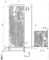
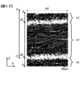
- Cross-sectional image of one embodiment of the CFRP of the present invention Binarized image of Fig. 2 Z-axis distribution of Vcf in the cross section of FIG. 3 and an enlarged view of a part thereof Z'-axis distribution of Vcf in layer L1 of FIG.
- Low Vcf domain refers to a region (domain) identified by the measurement method described in the "Identification of low Vcf domain” section.
- Layer means a layered region that constitutes a part of a carbon fiber reinforced composite material, the carbon fibers contained in the region have the same fiber orientation angle, and the carbon fibers contained in adjacent layered regions refers to a layered region whose fiber orientation angle is different from , that is, a layered region in which the boundary surface with an adjacent layered region is determined by the fiber orientation angle of the carbon fibers included in the region.
- a “specific layer” refers to a layer that satisfies the following (1) to (3) at the same time.
- the thickness is 150 ⁇ m or more.
- the average value of the carbon fiber volume content Vcf is 50% or more.
- the average value of Vcf is 1, low Vcf domains with Vcf of 0.5 or less are included in the surface layer and inner layer of the specific layer.
- Average value means the arithmetic mean value unless otherwise specified.
- the average value is obtained for the data acquired according to the setting of the measuring device.
- CF is usually used as a "tow” in which about 1,000 to 1,000,000 single fibers are aggregated in a tape shape.
- the carbon fiber sheet (hereinafter referred to as CF sheet) used in the present invention has CFs aligned in one direction, and can preferably be obtained by arranging the tows.
- a CF sheet arranged in one direction (UD) in the longitudinal direction of the CF or a carbon fiber reinforced resin impregnated with a matrix resin (hereinafter referred to as a CF reinforced resin) is called a UD material.
- NCF Non Crimp Fabric
- CFRP Carbon fiber reinforced composite material
- the CFRP according to the present invention can be obtained by molding an intermediate substrate obtained by impregnating a CF sheet with a matrix resin.
- a prepreg is used as the intermediate base material, it can be laminated and molded.
- a resin infusion method may be used in which resin is injected into a laminate of unimpregnated CF sheets and molded.
- UD materials are laminated in multiple directions. “Lamination in multiple directions” refers to a state in which a plurality of UD materials are stacked with different orientation angles of the fibers.
- the CF is oriented in two or more different directions.
- a laminate obtained by laminating a UD material in multiple directions and a base material other than the UD material may be combined.
- the matrix resin is cured.
- CFRP of the present invention it is important that the electrical conductivity in the thickness direction of CFRP is 10 S/m or more. As a result, the conductivity between adjacent layers can be sufficiently increased, and a sufficient edge glow suppression effect can be obtained as described later.
- the thickness direction conductivity of CFRP is preferably 15 S/m or more, more preferably 20 S/m or more.
- a region in which the carbon fiber sheet has the same fiber orientation angle continuously in the thickness direction is called a layer. It is important to include at least one "specific layer" among the layers that satisfies the above conditions (1) to (3) at the same time.
- FIG. 1 shows a schematic of one embodiment of the CFRP of the present invention, in which 100 denotes a "specific layer".
- the thickness T100 of the layer 100 is measured from the center point in the thickness direction of the lower inter-layer resin layer 30 at T100 to the thickness of the upper inter-layer resin layer 20. Defined as the distance to the center point in the thickness direction. If the existence of a resin layer between layers cannot be confirmed, or if the existence of a resin layer is unclear, as will be described later, the boundary between layers, such as those obtained by laminating a plurality of prepregs, should be considered.
- the Z-coordinate is obtained as the Z-coordinate of the point where Vcf is the minimum value in the neighborhood between layers. Further, if the thickness of the "specific layer” is 150 ⁇ m or more, the production of the intermediate base material and its lamination efficiency are high, which is preferable. Especially in prepreg, the effect is remarkable.
- the thickness of the "specific layer” is preferably 240 ⁇ m or more, more preferably 300 ⁇ m or more. If the layer thickness is too thick, the mechanical properties may deteriorate, so it is preferably 700 ⁇ m or less.
- the average value of the carbon fiber volume content Vcf in the "specific layer” is 50% or more, the conductivity in the thickness direction of CFRP can be increased. From the same point of view, the average value of Vcf is preferably 60% or more. On the other hand, if the average value of Vcf is excessively high, voids may occur in the CFRP and the mechanical properties may deteriorate. is more preferable.
- the average value of Vcf in the "specific layer” means the volume content ratio of CF contained in the layer 100 with respect to the layer 100, and can be calculated by a method described later.
- a domain means a region having a certain size
- the presence of a low Vcf domain means the presence of a region with a smaller Vcf than elsewhere in the layer 100, and as described above, "specific Assuming that the average value of Vcf of the "layer” is 1, a region where Vcf is 0.5 or less (hereinafter sometimes referred to as "Vcf ratio of 0.5 or less” for short) is defined as a low Vcf domain. Specifically, it is identified by the measurement method described in the section "Identification of low Vcf domains" below.
- the low Vcf domains 110 may be linked together or independent of each other.
- a definition of the low Vcf domain is provided below.
- the surface layer and inner layer of the "specific layer” refer to, as described later, when the "specific layer” is divided into four equal thicknesses in the thickness direction, the surface side two sections are the surface layer and the inner two sections are the inner layer. be.
- the chance of CF contact between adjacent layers increases, the conductivity between adjacent layers can be increased, and the edge glow is effective. can be effectively suppressed.
- the number of low-Vcf domains in the inner layer is increased, the carbon fibers in the entire layer can be spread out, thereby suppressing local contact between the carbon fibers contained in adjacent layers and reducing the variation in conductivity. can be done.
- the area ratio of the low-Vcf domain existing in the surface layer and the area of the low-Vcf domain existing in the inner layer is preferably in the range of 90:10 to 10:90. More preferably 80:20 to 20:80, still more preferably 70:30 to 30:70.
- the range may be a combination of any of the above upper limits and any of the above lower limits.
- the particles are contained in at least one low Vcf domain. Thereby, a low Vcf domain can be stably formed.
- the contained particles are conductive particles, the conductivity is further improved, and the risk of edge glow can be reduced.
- the toughness of CFRP can be improved.
- the matrix resin used in the CFRP of the present invention preferably contains a thermosetting resin, a thermoplastic resin and a curing agent, but may be a thermosetting resin and a curing agent, or may be a thermoplastic resin alone.
- Epoxy resins are generally used as thermosetting resins, and epoxy resins whose precursors are amines, phenols, and compounds having a carbon-carbon double bond are particularly preferred.
- epoxy resins having amines as precursors tetraglycidyldiaminodiphenylmethane, triglycidyl-p-aminophenol, triglycidyl-m-aminophenol, various isomers of triglycidylaminocresol, and phenols are used as precursors.
- Epoxy resins used as the body include bisphenol A type epoxy resin, bisphenol F type epoxy resin, bisphenol S type epoxy resin, phenol novolak type epoxy resin, cresol novolak type epoxy resin, and a compound having a carbon-carbon double bond as a precursor.
- the epoxy resin to be used include, but are not limited to, alicyclic epoxy resins and the like.
- thermosetting resin is preferably used in combination with a curing agent.
- an epoxy resin any compound having an active group capable of reacting with an epoxy group can be used as the curing agent.
- Compounds having an amino group, an acid anhydride group, or an azide group are preferred.
- dicyandiamide, various isomers of diaminodiphenylsulfone, and aminobenzoic acid esters are suitable.
- dicyandiamide is preferably used because it is excellent in preservability of the prepreg.
- various isomers of diaminodiphenylsulfone are most suitable for the present invention since they give a cured product having good heat resistance.
- trimethylene glycol di-p-aminobenzoate and neopentyl glycol di-p-aminobenzoate are preferably used. Because it is excellent, it is selected and used according to the application. Also, of course, it is possible to use an expensive catalyst if necessary. In order to improve the pot life of the coating liquid, it is also possible to use a complexing agent capable of forming a complex with a curing agent or a curing catalyst.
- thermosetting resin In addition, in the present invention, it is also preferable to use a mixture of a thermosetting resin and a thermoplastic resin as the matrix resin. Mixtures of thermosets and thermoplastics give better results than thermosets alone. This is because thermosetting resins generally have the disadvantage of being brittle but can be molded at low pressure using an autoclave, whereas thermoplastic resins generally have the advantage of being tough but are difficult to mold at low pressure using an autoclave. This is because the physical properties and moldability can be balanced by mixing and using them. When mixed and used, from the viewpoint of the mechanical properties of CFRP obtained by curing the prepreg, it is preferable that the thermosetting resin is contained in an amount of more than 50% by mass.
- the thermoplastic resin has a main chain selected from carbon-carbon bonds, amide bonds, imide bonds, ester bonds, ether bonds, carbonate bonds, urethane bonds, urea bonds, thioether bonds, sulfone bonds, imidazole bonds, and carbonyl bonds. Polymers with bonds can be used.
- PPS, PES, PI, PEI, PSU, PEEK, PEKK, PAEK and the like are suitable for fields such as aircraft applications where heat resistance is required.
- polyolefins such as polypropylene (PP), PA, polyester, PPS, etc. are suitable in order to increase molding efficiency.
- PP polypropylene
- PA polypropylene
- polyester polypropylene
- PPS polypropylene
- these may be polymers, or may be oligomers or monomers for low viscosity and low temperature application.
- these may be copolymerized, or various types may be mixed and used as a polymer blend alloy.
- the low Vcf domains in the CFRPs of the invention include particles.
- particles refer to particulate solid substances having a short diameter of 1 ⁇ m or more and existing in CFRP. Therefore, the conductive aids and nanofillers to be described later do not correspond to the particles referred to in the present invention.
- the thickness of the carbon fiber sheet appears to be thicker, which actually causes the inter-layer resin layer to become thinner, and between the "specific layer” and the layer adjacent to the "specific layer (inter-layer resin (equivalent to a layer) can form a large number of conductive paths relatively uniformly in the plane.At this time, due to the volume exclusion by the particles, the single yarns in contact are gently curved, so A large volume space can be effectively created inside the carbon fiber sheet.With many relatively uniform conductive paths in the plane, the edge glow suppression effect due to the high conductivity in the thickness direction and the edge glow suppression effect can be achieved. CFRP with small internal variation is obtained.
- the CFRP cross-sectional photograph shown in the lower part of FIG. 9 can be obtained by observing it at a magnification of 200 times or more using a laser microscope (ultra-depth color 3D shape measuring microscope VK-9510: manufactured by KEYENCE CORPORATION).
- Circular objects such as S2' and S3' can be identified as particles because they have a shadow difference with the surroundings and both the major axis and the minor axis are 1 ⁇ m or more. It should be noted that there is a part that looks black like S3', but it is considered that this is because traces of falling off particles look black. Then, for example, when S2 in the upper part of FIG. 9 is compared with S2' in the lower part of FIG.
- At least one low Vcf domain contains particles, but it is not essential that all low Vcf domains contain particles, and there may be low Vcf domains that do not contain particles.
- the particles introduced together with the resin widen the gaps between the carbon fibers in the carbon fiber sheet, so that the carbon fiber monofilaments that are in contact with the domains in which the particles are present are gently curved. Therefore, there may be a low Vcf domain in which particles are not observed in the cross-sectional image, such as the low Vcf domain S4 and the domain S4' corresponding to the cross-sectional image portion of CFRP.
- the sphericity of the particles used in the present invention is preferably 0.9 or more.
- the sphericity of the particles is 0.9 or more, regardless of the direction of the long axis and short axis of the particles introduced into the carbon fiber sheet, the introduction of the low Vcf domain and the apparent thickness of the carbon fiber sheet can be increased.
- the types of particles are determined without distinguishing between them.
- the sphericity is determined by randomly selecting 30 particles from the CFRP cross-sectional photograph and using the minor axis and major axis thereof according to the following formula. At this time, if it can be confirmed that the CFRP cross-sectional photograph is of the same kind as the particles contained in the low Vcf domain, it is not necessary to use the same image as the image obtained by observing the low Vcf domain.
- S sphericity
- a major axis
- b minor axis
- n number of observations.
- the median diameter Dm of the particles used in the present invention is preferably 6 ⁇ m or more. By setting the median diameter of the particles to 6 ⁇ m or more, it is possible to efficiently introduce a low Vcf domain and increase the apparent thickness of the carbon fiber sheet. Dm is preferably 10 ⁇ m or more, more preferably 15 ⁇ m or more. In determining the median diameter, when a plurality of types of particles are included, the types of particles are determined without distinguishing between them.
- the median diameter Dm of the particles means that 30 particles are randomly selected from the CFRP cross-sectional photograph, and the diameter D of the particles is the arithmetic mean value of the minor axis b and the major axis a.
- the value in the middle rank is called the median diameter. That is, when the 30 values are arranged in order of size and D1 ⁇ D2 ⁇ .
- the CFRP cross-sectional photograph does not have to be the image obtained by observing the low Vcf domain previously.
- the ratio of particles with a diameter of 50 ⁇ m or more is 10% or less when the total number of particles is 100%. This suppresses the particles from being filtered when they are introduced into the carbon fiber sheet, allowing the particles to be efficiently introduced into the carbon fiber sheet, which is advantageous for the formation of low Vcf domains. Become. It is preferably 5% or less, more preferably 2% or less. In determining the ratio of particles with a diameter of 50 ⁇ m or more, when a plurality of types of particles are included, the types of particles are determined without distinguishing between them. At this time, the CFRP cross-sectional photograph may not be the image obtained by observing the low Vcf domain previously.
- At least one type of particles used in the present invention is preferably conductive particles. Since the particles are conductive particles, the part where the particles are in contact becomes a conductive path, so the apparent thickness of the carbon fiber sheet can be increased and the conductivity of the carbon fiber sheet itself can be secured, and the carbon fiber sheet itself can remain on the surface layer. Since the formed conductive particles form a conductive path with the adjacent layer, the conductivity of the entire CFRP can be effectively improved.
- the conductive particles used in the present invention metal particles, metal oxide particles, metal-coated inorganic particles, organic polymer particles, carbon particles, and the like can be used. Among them, carbon particles are preferable because they do not cause corrosion even when used in aircraft.
- carbon particles having a (002) interplanar spacing of 3.4 to 3.7 angstroms is preferable because it facilitates improvement in electrical conductivity.
- ICB manufactured by Nippon Carbon Co., Ltd. has a (002) interplanar spacing of 3.53 angstroms, and is a substantially spherical carbon particle. 168, 157-163 (1995). It is described in. Further, it is described that the true spherical carbon particles are very hard and hardly deform even when compressive deformation is applied, and that the particle shape returns to its original shape when the compression is removed.
- FRP is used as a structural material for an aircraft, the structural material is deformed, as typified by the bending of the main wing during flight. Since it is difficult to have a significant deformation, it is expected to exhibit stable conductivity.
- the conductive aid refers to a conductive material having particles with a short diameter of less than 1 ⁇ m.
- a nano-filler made of a carbon material is added as a conductive aid to increase the conductivity of the CFRP obtained in the present invention.
- the nanofiller made of a carbon material is not particularly limited, and examples thereof include carbon nanofiber, carbon nanohorn, carbon nanocone, carbon nanotube, carbon nanocoil, carbon microcoil, carbon nanowall, carbon nanochaplet, fullerene, and carbon black. , graphite, graphene, carbon nanoflakes, and derivatives thereof.
- Nanofillers made of these carbon materials may be used singly or in combination of two or more.
- carbon black which is inexpensive and has a high conductivity-imparting effect, is preferable from a comprehensive point of view such as supply/price and conductivity-imparting effect.
- Carbon black is carbon-based fine particles generally produced by controlling the number average particle size of primary particles to 3 to 500 nm. Examples of such carbon black include furnace black, hollow furnace black, acetylene black, and channel black.
- At least one type of particles is preferably polymer particles.
- polymer particles By containing polymer particles, a low Vcf domain can be formed while suppressing the amount of expensive conductive particles used.
- Polyamide particles, polyimide particles, and the like can be preferably used as the polymer particles, but polyamide particles are more preferable in consideration of cost.
- Polyimide particles are preferably used when high heat resistance is required.
- Polyamides include nylon 12, nylon 11, nylon 6, nylon 66 and nylon 6/12 copolymers, and semi-IPN (polymer interpenetrating network structure) with the epoxy compound described in Example 1 of JP-A-01-104624.
- Nylon (semi-IPN nylon) or the like can be preferably used.
- the CFRP of the present invention is the average number of particles within a distance of 2Dm from the center of each particle in the "specific layer", where Dm is the median diameter of the particles contained in the "specific layer”. is preferably 3.5 or less.
- the particles are introduced into the carbon fiber sheet together with the resin, effectively increasing the apparent thickness of the carbon fiber sheet.
- the number is 1 or less, each particle is uniformly dispersed in the FRP, and the apparent thickness of the carbon fiber sheet can be effectively increased.
- it is 2.5 or less.
- the types of particles are determined without distinguishing between them.
- particles refers to particles that do not contain the above-described conductive aid or nanofiller and have a short diameter of 1 ⁇ m or more.
- the means for making the average number of particles within a distance of 2Dm from the center of the particle in the specific layer to be 3.5 or less, where Dm is the median diameter of the particles, is not particularly limited, but the diameter and distribution of the particles to be used are not particularly limited. or by controlling the conditions when the particles to be described later are introduced into the carbon fiber sheet together with the resin.
- the average number of particles within a distance of 2Dm from the particle center in a specific layer is obtained by randomly selecting 30 particles from the CFRP cross-sectional photograph and obtaining the number of particles within a distance of 2Dm from the particle center. is determined by counting and averaging this over the previous 30 random selections.
- the CFRP cross-sectional photograph may not be the image obtained by observing the low Vcf domain previously.
- the distance from the center of each particle in the "specific layer” to the center of the closest particle is The average is preferably 1.2 Dm or more, more preferably 1.5 Dm or more.
- the method of making the average distance from the center of the particle to the center of the nearest particle in the specific layer 1.2 Dm or more is not particularly limited, but the diameter and distribution of the particles used can be adjusted, or the particles described later can be added to the carbon fiber sheet. It can be achieved by controlling the conditions when introducing into.
- the average distance from the center of a particle in a specific layer to the center of the nearest particle is obtained by randomly selecting 30 particles from the CFRP cross-sectional photograph and measuring the distance from the center of the particle to the center of the nearest particle. is measured on the cross-sectional photograph and averaged over the above 30 randomly selected samples.
- the CFRP cross-sectional photograph may not be the image obtained by observing the low Vcf domain previously.
- the number of carbon fibers contained in at least one of the carbon fibers contained in the "specific layer” and the layers adjacent to the “specific layer” is 5 or more per 2 mm in the plane direction of the layer. preferably in contact. More preferably 20 or more, more preferably 40 or more are in contact. The larger the number of contacts, the easier it is to form a conductive path, which is preferable. A method for identifying carbon fibers in contact with carbon fibers contained in adjacent layers will be described later. Thereby, a conductive path is formed with an adjacent layer, and edge glow can be effectively suppressed.
- the number of carbon fibers in contact with this adjacent layer is at least 1 per 0.4 mm in the plane direction of the "specific layer".
- at least one or more carbon fibers are in contact with each other every 0.4 mm means that one or more carbon fibers are always in contact with each other when a 0.4 mm region is observed in the layer plane direction.
- at least one or more carbon fibers are in contact with the carbon fibers of the adjacent layer in all of the 5 regions.
- At least one carbon fiber is in contact with the carbon fiber of the adjacent layer at intervals of 0.4 mm, making it possible to form conductive paths evenly within the CFRP plane, suppressing variations in conductivity within the PPg plane. becomes possible.
- it is at least 3 or more per 0.4 mm in the layer plane direction, more preferably at least 5 or more per 0.4 mm in the layer plane direction. Since at least one carbon fiber is in contact with the carbon fiber of the adjacent layer at intervals of 0.4 mm, it is possible to form conductive paths uniformly within the CFRP plane, and to suppress variations in conductivity.
- a layer is defined as a region including a region in which the CF sheet has the same fiber orientation angle continuously in the thickness direction. Its specific meaning is as described above. A region in which no fiber exists in the layer may exist as a "low Vcf domain" to be described later.
- the CFRP according to the present invention inevitably has a plurality of layers because CF sheets in which CF is arranged in one direction are laminated in multiple directions.
- the present invention includes at least one layer (specific layer) that simultaneously satisfies the above conditions (1) to (3).
- a layer that does not satisfy the condition of "specific layer” may be called a normal layer.
- the layer 100 is the "specific layer", so this will be described in detail as an example.
- layers 200 and 300 having different fiber orientation angles from the layer 100 are adjacent to the upper and lower sides of the layer 100 (hereinafter sometimes referred to as adjacent layers).
- Interlayer resin layers 20 and 30 are present between the layer 100 and the layers 200 and 300 .
- the thickness of each inter-layer resin layer is T20 and T30.
- the interlayer resin layers 20, 30 may not exist.
- the definition of the inter-layer resin layers 20 and 30 will be described later.
- Layer 100 has a "low Vcf domain 110" (represented by a box) in which the ratio of the overall Vcf of layer 100 to the average value is less than 0.5.
- the layer 100 can be divided into four equal distances in the thickness direction, and can be divided into an inner layer 160 (for two sections) and surface layers 150 and 151 .
- the "specific layer” has an area ratio of the low-Vcf domain existing in the surface layer and the low-Vcf domain existing in the inner layer when the cross section of the "specific layer” is viewed. is preferably 90 (this limitation may be hereinafter referred to as “condition (4)”), where, as in condition (4), in the cross section of the “specific layer”, the low Vcf domain present in the surface layer and the inner layer It is preferred that the area ratio with the low Vcf domain present in the region is in the range of 90:10 to 10:90. “Area” here means the area of the boxed portion of the low Vcf domain 110 . In FIG.
- the low Vcf domain is modeled by enclosing it in a square, and a method for specifying the low Vcf domain will be described later.
- FIG. 1 assuming that the three low Vcf domains 110 have the same area, the inner layer 160 has two Vcf domains 110 and the surface layer 151 has one Vcf domain 110.
- the area ratio of the low Vcf domain existing in the surface layer and the Vcf domain existing in the inner layer is 33:67.
- the fibers in the layer 100 are spread around the low Vcf domain, efficiently A low Vcf domain eliminates the volume in layer 100, allowing the overall layer 100 to be thick, allowing many CF-to-CF contacts to be obtained between the "specific layer” and adjacent layers.
- the range is preferably 80:20 to 20:80, more preferably 70:30 to 30:70. This form can be formed by the method described below.
- the low Vcf domain may contain particles. By including particles, the entire layer 100 can be efficiently thickened, and contact between many CFs can be obtained between the specific layer and adjacent layers. This effect will be described later.
- a layer such as the layer 100 that satisfies the conditions (1) to (3) is called a "specific layer" in the present invention.
- the layers 200 and 300 are normal layers unlike the layer 100 in FIG. 1, but may be "specific layers”.
- Vcf is effective for improving the conductivity in the thickness direction of CFRP.
- the amount of the matrix resin in the layer usually decreases, so the impregnation of the matrix resin into the CF sheet becomes insufficient, and voids may easily occur in the CFRP.
- the low Vcf domain 110 expands the carbon fiber sheet from the inside in the layer 100, which is the "specific layer", so that the substantial Vcf can be increased even if the Vcf average value is constant.
- the specific layer Preferably, the low Vcf domain is present at 1% or more and 50% or less. More preferably, it is 2% or more and 50% or less. More preferably, it is 3% or more and 50% or less.
- FIG. 2 is an example of a cross-sectional photograph of the CFRP of the present invention, showing part of the layer L1, which is a "specific layer", and normal layers L2 and L3.
- the fiber orientation angles of L1 and CF are different between L2 and L3.
- the orientation angles of the CFs in the layers are the same, but this allows for the disturbance of the flow level of the CFs due to the influence during molding.
- the cross-sectional shape of the CF is generally observed to be elliptical, and a region in which the length of the long axis of the ellipse is substantially the same and which is continuous in the thickness direction is determined to be one layer. Further, if it is understood that the orientation angle of CF is the same in regions continuous in the thickness direction at the stage of laminating the prepregs, the prepregs may be formed into one layer.
- the positive direction of the X-axis is defined as the rightward direction on the paper surface, and the positive direction of the Z-axis is defined as the upward direction on the paper surface.
- the boundary between the "specific layer” L1 and the adjacent layers L2 and L3 is determined from the Z-axis direction distribution of Vcf.
- the distribution of Vcf in the Z-axis direction can be obtained as follows. First, using image analysis software, a cross-sectional photograph (FIG. 2 is taken as an example) is binarized by separating the CF (black) and the matrix resin (white) by a threshold that can be distinguished (FIG. 3). At this time, the image shown in FIG. 2 must have a resolution such that the length of one side of one pixel is 0.3 ⁇ m or less, and the range in the X-axis direction must be 1000 ⁇ m or more.
- Vcf can be calculated from the area ratio of the black portion representing CF.
- Vcf is calculated using a rectangular area (here, 1000 ⁇ m) with a length of one pixel in the Z-axis direction (here, 0.2 ⁇ m) and a whole X-axis length (W1) in the X-axis direction in the image as an evaluation area.
- the Vcf distribution in the Z-axis direction can be obtained by calculating the Vcf of the evaluation region for each 0.2 ⁇ m length, which is the length of one pixel in the Z-axis direction, from the origin of the Z-axis.
- the Z-direction distribution of Vcf obtained from FIG. 3 is shown in FIG. 4 (the origin is O).
- the Z coordinates (Z2, Z3 in Fig. 3) of the boundary with the adjacent layer are determined.
- the median value of Vcf is calculated from the Z-axis direction distribution of Vcf shown in FIG.
- the median value of Vf is the value in the middle when all the obtained Vf values are arranged in order of magnitude.
- Vcf tends to change depending on the range of the Z-axis direction observation area of the cross-sectional photograph. This is because it is considered that A value obtained by multiplying the median value of Vcf (A1 in FIG. 4) by 0.5 is used as a threshold for defining an inter-layer resin layer between adjacent layers. This threshold corresponds to B1 in FIG. In the vicinity of the boundary with the adjacent layer, a portion where Vcf is equal to or less than the threshold value B1 is defined as an inter-layer resin layer. In the upper diagram of FIG.
- I1 is regarded as an inter-layer resin layer between layers L1 and L3.
- the inter-layer resin layer thickness is defined as the length of the Z-coordinate of the portion corresponding to the inter-layer resin layer.
- T30 corresponds to the thickness of the inter-layer resin layer.
- the Z-coordinate of the boundary with the adjacent layer is defined as the central value of the Z-coordinate of the portion corresponding to the inter-layer resin layer.
- Z3 corresponds to the Z coordinate of the boundary between layers L1 and L3.
- the Z-coordinate of the boundary with the adjacent layer is defined as the Z-coordinate of the point showing the minimum value of Vcf in the vicinity of the boundary with the adjacent layer.
- Z2 is the Z coordinate of the boundary between layers L1 and L2, which is the Z coordinate of point J1 showing the minimum value of Vcf near the boundary between layers L1 and L2.
- the area of the "specific layer" L1 in the Z-axis direction is the range from Z3 to Z2, which is the Z-coordinate of the boundary with the adjacent layer.
- FIG. 5 shows the Z'-direction distribution of Vcf in the "specific layer” L1.
- the thickness T100 of the "specific layer” L1 is defined as the maximum value of the Z' coordinate, which is the value obtained by subtracting Z3 from Z2.
- the average value of Vcf in layer L1 is defined by the average value of the Z' direction distribution of Vcf. This value corresponds to C1 in FIG. A value of 0.5 times C1 is taken as the threshold for defining the low Vcf domain.
- the thickness E1 at the 1/4 point of the total thickness and the thickness F1 at the 3/4 point of the total thickness are the thicknesses for distinguishing between the inner layer and the surface layer, respectively.
- the total thickness of 418 ⁇ m from 105 ⁇ m or more (fractions are rounded up) to 314 ⁇ m or less (range of E1 to F1 in FIG. 5), which is the quarter point. ) is the inner layer, and the rest is the surface layer.
- Vcf domains A method for identifying the low Vcf domain will be described using FIG. 3 described above as an example.
- the size and location of the low Vcf domain are identified from the Vcf distribution in the "specific layer".
- the distribution of Vcf in the layer is judged from the thickness direction cross-sectional image of Vcf.
- the distribution of Vcf can be obtained as follows.
- the resolution is such that the length of one side of one pixel is 0.3 ⁇ m or less, the X-axis direction is in the range of 1000 ⁇ m or more, and the thickness direction is in the range from Z2 to Z3 derived from the layer thickness analysis.
- This range is hereinafter referred to as an analysis range.
- image analysis software for example, ImageJ (developer: Wayne Rasband, National Institutes of Health) or the like can be used.
- ImageJ developer: Wayne Rasband, National Institutes of Health
- the Vcf distribution within the analysis range is derived. Taking FIG.
- Vcf of an arbitrary pixel P1 is calculated from the area ratio of the black portion representing CF.
- Microsoft Excel 2016 or the like can be used as calculation software.
- an arbitrary pixel P1 is shifted by one pixel, and this calculation is performed over the entire analysis range K1.
- FIG. 7 shows the result of deriving Vcf for the entire analysis range K1 in FIG.
- FIG. 8 shows a range including pixels with a Vcf ratio of 0.5 or less (hereinafter referred to as low-Vcf pixels) when the average value of Vcf of the entire layer is set to 1 for this analysis result.
- one low Vcf domain is defined as a portion where the Vcf ratio is 0.5 times or less (low Vcf pixel) exists singly or continuously. Contiguous here means that at least one of the eight pixels adjacent to any low Vcf pixel is a low Vcf pixel.
- the area ratio of the low Vcf domains in the "specific layer” when the cross-sectional area of the out-of-plane direction cross section of the entire “specific layer” is 100% is the total area of the low Vcf domains in the "specific layer”.
- "It is a value divided by the area of the analysis range K1, which is the overall area.
- the out-of-plane direction cross section refers to, for example, the XZ plane in FIG. 8, and is a cross section cut along a plane including a direction perpendicular to the CF orientation direction and the thickness direction.
- the layer 100 is divided into four parts in the thickness direction, namely the inner layer 161 and the surface layers 152 and 153 .
- the area ratio of the low Vcf domain existing in the surface layer of the specific layer and the Vcf domain existing in the inner layer is defined by the range of W1 in the X-axis direction and Let S be the total number of cells with a Vcf ratio of 0.5 or less, which are included in the regions surrounded by the surface layers 152 and 153, and the range of W1 in the X-axis direction and the region surrounded by the inner layer 161 in the Z-axis direction. The ratio is calculated by S/I, where I is the total number of cells with a Vcf ratio of 0.5 times or less.
- the layer plane direction is, for example, the X-axis direction in FIG. This is the X-axis direction when observing the CFRP cross section so that the XYZ axis is taken as shown in FIG.
- FIG. 2 shows examples G1, G2, G3 of carbon fibers in contact with adjacent layers, respectively. Whether or not adjacent layers and carbon fibers are in contact is judged to be in contact with each other if the distance between the centers of gravity in the cross section of the carbon fibers is less than three times the average diameter of the carbon fibers.
- Example of carbon fibers in contact with adjacent layers In G1, for a set of carbon fibers, the distance between the centers of gravity of the carbon fibers is less than 3 times the average diameter of the carbon fibers, so one carbon fiber is in the adjacent layer determine that it is in contact with Similarly, for carbon fiber examples G2 and G3 in contact with adjacent layers, for a pair of carbon fibers, the distance between the centers of gravity of the carbon fibers is less than three times the average diameter of the carbon fibers, so each Determine that carbon fibers are in contact with adjacent layers.
- the number of carbon fibers that make up the "specific layer” and the carbon fibers contained in at least one adjacent layer with a different fiber orientation angle are in contact with each other per 2 mm in the layer plane direction is the same as in the case of G1 to G3. is carried out for 2000 ⁇ m in the X-axis direction, which is the layer plane direction, between adjacent layers, and the total number is counted.
- w11 and w12 in FIG. 2 are sections obtained by dividing the "specific layer” by 0.4 mm.
- "Specific layer” The number of carbon fibers in contact with each other in the plane direction of 0.4 mm is, for example, for the section w11 or w12, the number of carbon fibers in contact with the adjacent layer corresponding to the width of w11 or w12, respectively. refers to the number of In order to determine the variation in the number of carbon fibers in contact with adjacent layers, it is necessary to continuously observe five 0.4 mm sections. Continuity means that observation intervals are adjacent like w11, w12, w13, . . . as shown in FIG.
- one or more carbon fibers are always in contact with each other.
- one or more carbon fibers are in contact with each other, which means that this is continuously observed in a total of 5 sections.
- CFRP 1000 layers 200 and 300 having different fiber orientation angles from layer 100 are adjacent to the upper and lower sides of layer 100, respectively.
- High conductivity between layers facilitates the flow of current in and out of the layers.
- the current can be distributed over multiple layers, the electrical resistance between the inflow and outflow of the lightning current will decrease, and the potential difference will decrease.
- the potential difference between the current inflow portion and the current outflow portion is reduced, the potential difference generated in the CFRP as a whole is also reduced, so that the potential difference between adjacent layers is also reduced.
- the effect of suppressing edge glow is obtained by reducing the potential difference between adjacent layers.
- CFRP has strong anisotropy in conductivity, current tends to flow mainly only in the CF direction within each layer.
- the current concentrates in the CF connecting the bolts. Since the conductivity in the fiber direction is relatively high, in this case the electrical resistance between the two bolts is low and the potential difference between the bolts is small.
- the current must flow in the orthogonal direction within the layer after spreading along the CF connected to the bolt. Since the conductivity in the orthogonal direction is generally about 1,000 times smaller than the conductivity in the fiber direction, in this case the electrical resistance between the two bolts is high and the potential difference between the bolts is large.
- the conductivity between the layers determines the potential difference between the layers. If the conductivity between layers is high, current can flow easily between the adjacent layers without increasing the potential difference between the adjacent layers. In this case, the electrical resistance between the two bolts becomes small and the potential difference becomes small.
- Induction welding is a technique of joining by melting the thermoplastic resin of CFRP by induction heating and applying pressure separately. Induction heating is to generate an induced current in the CFRP by passing an alternating current through a coil installed outside the CFRP, and heat the CFRP by Joule heat generated by the induced current. In induction welding, it is desired to raise the induction heating temperature with less input energy.
- the amount of induced current generated in CFRP can be compared by eddy current testing.
- Eddy current testing is generally a test for detecting cracks and the like in CFRP through evaluation of induced current generated in CFRP.
- a coil is installed near the CFRP, and the magnetic field generated by the induced current is evaluated from the impedance change of the coil.
- K According to Mizukami et al. (Journal of Polymer Testing, Vol. 69, p. 320-324, 2018), the magnetic field generated by the induced current is evaluated from changes in the series resistance component of the coil. It is shown that the greater the change in the magnetic field, that is, the greater the amount of induced current, the greater the series resistance component of the coil.
- a layer that satisfies the condition of a "specific layer” can be arranged within the second layer counted from the upper or lower surface of the CFRP, that is, the outermost layer or the layer one layer inside. preferable.
- the induced current can be increased intensively in the vicinity of the CFRP surface, which serves as the welding surface, and heating can be efficiently performed.
- the “specific layer” 100 is arranged second when counting the number of layers from the upper surface of the CFRP 1000, and when the upper surface is the welding surface, the vicinity of the upper surface is efficiently It is possible to inductively heat the Layers other than the "specific layer” 100 may satisfy the conditions of the "specific layer", or may be normal layers.
- the "specific layer” has a form in which two or more layers are continuously laminated. Between the “specific layers”, the conductivity of the portions where these are adjacent is greatly improved, and the effect of suppressing the edge glow or improving the induction heating temperature is further enhanced. From the viewpoint of suppressing edge glow and improving induction heating temperature, it is also preferable that all layers are "specific layers”.
- FIG. 10 is a cross-sectional view showing one form of conventional normal (non-interlayer reinforced) CFRP.
- Vcf is almost uniform regardless of location, and It is not a structure in which a low Vcf domain is present. If the total thickness of the layers and the average value of Vcf of the layers are the same, the present invention shown in FIG. 1 is better than the conventional technology shown in FIG.
- the frequency of contact between CFs between layers with different fiber orientation angles increases, and the conductivity between layers with different fiber orientation angles can be improved.
- FIG. 11 is a cross-sectional view showing one form of conventional interlayer reinforced CFRP different from FIG.
- CFRP shown in FIG. 11 in layers with the same fiber orientation angle, there is no structure in which low Vcf domains exist in the layers, and thick interlayer resin layers 24 and 34 exist between the layers.
- Such inter-layer resin layers 24 and 34 are mainly resin-rich layers for improving toughness, and often contain thermoplastic resin particles, fibers, non-woven fabric, etc. inside. Even if the layer thickness and the average value of Vcf are the same, the inter-layer resin layers 24 and 34 often need to have a certain thickness or more in the interlayer reinforced CFRP. The cost of the present invention is higher because they are more likely to come into contact with each other.
- FIG. 12 shows a cross-sectional photograph of one form of conventional interlayer reinforced CFRP, which will be described in detail.
- FIG. 12 shows part of layer L4 and layers L5 and L6 of the CFRP consisting of layers L4, L5 and L6.
- FIG. 13 is obtained.
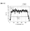
- the graph shown in FIG. 14 is obtained.
- the boundaries between layers are determined in the same manner as described above.
- the median value of Vcf is A1', which is the representative value of Vcf in the regions of layers L4, L5 and L6 included in the cross-sectional photograph.
- Multiplying A1' by 0.5 gives B1' as the threshold for defining the inter-layer resin layer.
- I1' and J1' where Vcf is lower than B1'.
- I1' and J1' are defined as inter-layer resin layers, and respective inter-layer resin layer thicknesses T34 and T24 are defined by the length of the Z coordinate of the portions corresponding to I1' and J1'.
- the central values of the Z coordinates of the portions corresponding to I1' and J1' are the Z coordinates of the boundaries of the layers L4 and L6, or the layers L4 and L5, respectively, and are Z6 and Z5, respectively.
- the Z'-axis direction distribution of Vcf in the layer L4 is obtained as shown in FIG.
- the thickness T104 of the layer L4 is defined as the maximum value of the Z' coordinate, which is the value obtained by subtracting Z6 from Z5.
- the average value of Vcf in layer L4 is defined by the average value of the Z' direction distribution of Vcf, and corresponds to C1' in FIG.
- a value of 0.5 times C1' is the threshold for defining the low Vcf domain and corresponds to D1'.
- Layer L4 has an overall Vcf average of 50% or more, but does not have a low Vcf domain, so there is no "specific layer” and is therefore not the CFRP of the present invention.
- FIG. 16 is a cross-sectional view of a CFRP that is different from conventional interlayer reinforced CFRP and also different from FIG. FIG. 16 has low Vcf domains 115 in layers 105 with the same fiber orientation angle.
- the low Vcf domain exists only near the surface layer 155 or 156 of layer 105 and does not satisfy condition (4).
- the introduced particles and resin cannot spread the carbon fiber sheet, or the introduced particles and resin can spread the carbon fiber sheet. Even if it can be done, it will push out the local surrounding CF near the layer surface, and the thickness variation between the layers 25 and 35 will increase.
- the method for producing the prepreg is not particularly limited, but for example, the following hot melt method can be used.
- a matrix resin is prepared by kneading a combination of an epoxy resin, an aromatic amine-type curing agent, a thermoplastic resin, and particles, and then the matrix resin is coated to produce a matrix resin film.
- a matrix resin film is laminated on a separately prepared CF UD sheet and impregnated to obtain a prepreg.
- the particles can be effectively flowed into the carbon fiber sheet together with the resin.
- the mechanism of the effect of such multistage pushing can be considered as follows. In the first push, the matrix resin is pushed into the CF sheet, but at the same time, the CF in the inner layer is densely packed, and the particle component flows into the inner layer of the CF sheet due to the filtering effect of the CF that is densely packed with particles. There may be restrictions.
- the CF springs back the CF single yarns are rearranged, and gaps are created between the CF single yarns, so that the second pushing makes it easier for the particles to flow into the inner layer of the CF sheet. It is considered to be a thing. For this reason, the greater the number of times of pressing, the more effective it is, but the number of times of pressing can be selected in consideration of the balance between the cost and size of the impregnation equipment and this effect. Generally, it is 2 times or more and 10 times or less.
- springing back the CF between the n-th pushing and the n+1-th pushing and keeping the viscosity of the matrix resin sufficiently low further enhances the particle inflow effect.
- reheat the prepreg between the second pressings It is preferable to reheat the prepreg between the second pressings.
- a method for reheating for example, contact heating such as a hot plate, non-contact heating such as an infrared heater, etc., and various heating devices such as a method of passing over a heating roll without applying pressure can be applied.
- the interval between the n-th pressing and the n+1-th pressing to 0.1 seconds or more and 5 seconds or less, the rearrangement effect of the CF single yarns due to springback can be obtained. Controls (reheating, pressing intervals, etc.) for improving the springback effect are particularly effective when performed between the first and second pressings.
- the thicker the prepreg the thicker the CF sheet. Even if it is a composite prepreg, it is possible to obtain a prepreg in which particles suitable as a precursor of the CFRP of the present invention have flowed into the inner layer of the CF sheet. Then, the inflow of particles can substantially form a high Vcf portion due to the volume exclusion effect as described above, and the conductivity of CFRP can be effectively improved. By using the above production method, a more remarkable effect can be obtained in producing a thick prepreg having a CF basis weight of 350 g/m 2 or more.
- the matrix resin is directly applied to the CF sheet by a die coater or a spray coater as described in WO 2018/173618 pamphlet, WO 2018/173619 pamphlet, etc.
- a method of applying and then impregnating can also be used.
- the CF sheet may be passed through a bath filled with a matrix resin, and the matrix resin may be impregnated at the same time as the application. Even at this time, additional impregnation can be performed after passing through the bath to enhance impregnation and particle inflow.
- the prepreg laminate After the prepreg laminate is obtained by laminating the prepregs described above, the prepreg laminate can be shaped by pressurization and heating, and can be molded by a so-called heat and pressure molding method in which the resin is cured.
- the heat and pressure molding method can be appropriately selected from press molding, autoclave molding, vacuum pressure molding, bagging molding, and the like.
- the temperature for molding CFRP is usually in the range of 130° C. to 220° C. when epoxy resin is used.
- the autoclave molding method is desirable when the main component of the matrix resin is a thermosetting resin, because it is easy to obtain a molding with few voids.
- the pressure for molding by the autoclave molding method varies depending on the thickness of the prepreg and the volume content of CF, but is usually from 0.1 MPa to 1.0 MPa. This makes it possible to obtain high-quality CFRP without defects such as voids.
- Aircraft structures include flat plate structures, cylindrical structures, box-shaped structures, C-shaped structures, H-shaped structures, L-shaped structures, T-shaped structures, I-shaped structures, Z-shaped structures, A hat-shaped structure etc. are mentioned. Aircraft parts are constructed by combining these structures. Details are described, for example, in "Airplane Structural Design” 5th Edition, Torikai and Kuze, Japan Aeronautical Engineering Association (2003). Such a structure can be obtained by shaping a prepreg, for example, as described in paragraph [0084] of WO2017/110991.
- a prepreg having a thick carbon fiber sheet is produced using the same method as the prepreg manufacturing method described above, and then a similar operation can be performed to obtain CFRP.
- the impregnation distance is longer than that in the production of prepreg having a CF basis weight of 270 g/m 2 class, it is preferable to increase the number of times of pressing.
- CF sheet having a desired CF basis weight is sandwiched between two matrix resin films to form a sheet.
- the resin content is set to 34% by mass.
- the temperature of the matrix resin film was raised to 60° C. or higher, the pressure was maintained at 3 MPa with a press for 5 seconds, the pressure was released, and the pressure was further increased. Hold at 3 MPa for 5 seconds.
- the time interval from depressurization to repressurization shall be 1 second or more and 5 seconds or less. In this way, a prepreg can be produced and CFRP can be molded.
- the thickness of the “specific layer” of the produced CFRP is about 520 ⁇ m.
- the average value of the carbon fiber volume content Vcf is about 60%, and when the average value of Vcf of the layer is 1, low Vcf domains with Vcf of 0.5 or less are present in the surface and inner layers,
- the area ratio of the low-Vcf domain existing on the surface layer of the "specific layer” and the low-Vcf domain existing on the inner layer is about 60:40.
- the area ratio of the low Vcf domain is about 8% when the cross-sectional area of the out-of-plane direction cross section of the entire layer is 100%.
- the conductivity in the thickness direction is about 28 S/m, and a high edge glow suppressing effect can be expected.
- two matrix resin films are prepared by using PEI as a thermoplastic resin and containing 4% by mass of carbon particles "Nikabeads (registered trademark)" ICB2020 as conductive particles.
- the CF sheets that are evenly aligned in one direction are sandwiched to form sheets for each leaf.
- the CF basis weight is set to 536 g/m 2 and the resin content is set to 34% by mass.
- the pressure is released and further maintained at a temperature of 340° C. and a pressure of 3 MPa for 3 minutes.
- the time interval from pressure release to re-pressurization is set to 1 second or more and 5 seconds or less.
- a prepreg is produced in this manner, and eight sets of the prepreg are laminated (alternating at 0°/90°) to produce a prepreg laminate. Then, this prepreg laminate is molded by a pressing machine at a temperature of 340° C. and a pressure of 3 MPa for 5 minutes to produce CFRP.
- the resulting "specific layer" in CFRP has a thickness of about 530 ⁇ m and an average Vcf of about 60%. exists in the surface layer and the inner layer, and the area ratio of the low Vcf domain existing in the surface layer of the layer and the low Vcf domain existing in the inner layer is about 70:30.
- the area ratio of the low Vcf domain is about 4% when the cross-sectional area of the out-of-plane direction cross section of the entire "specific layer” is taken as 100%.
- the thickness direction conductivity of CFRP is about 15 S/m, and the resistance change of the coil is sufficiently large, so excellent induction heating temperature can be expected.
- the present invention will be described in detail below with reference to examples. However, the present invention should not be construed as being limited to these examples.
- the unit "part" of a composition ratio means a mass part unless there is a comment in particular.
- measurements of various properties were performed under an environment of 23° C. temperature and 50% relative humidity unless otherwise noted.
- the pressure of the system reached 10 kg/cm 2
- the pressure was controlled while slightly releasing the steam so as to maintain the pressure at 10 kg/cm 2 .
- the pressure was released at a rate of 0.2 kg/cm 2 minutes.
- the temperature was maintained for 1 hour while flowing nitrogen to complete the polymerization, and the mixture was discharged into a water bath of 2,000 g to obtain a slurry. After dissolving the dissolved matter, filtration was performed, and 2,000 g of water was added to the filtrate and washed at 80°C.
- the powder thus obtained had a melting point of 218° C., which is the same as that of polyamide 6, and a crystallization temperature of 170° C.
- the particle size was measured using Microtrac MT3300II (light source 780 nm-3 mW, wet cell (medium: water)).
- Conductive particles carbon particles, hereinafter sometimes referred to as CP
- CP Conductive particles
- ICB4420 “Nikabeads (registered trademark)”
- ICB2020 (number frequency average particle size: 15 ⁇ m, manufactured by Nippon Carbon Co., Ltd.)
- ICB1020 “Number frequency average particle size: 12 ⁇ m, manufactured by Nippon Carbon Co., Ltd.”
- ICB0520 numberber frequency average particle size: 5 ⁇ m, manufactured by Nippon Carbon Co., Ltd.
- Large-diameter CP "Nikabeads (registered trademark)” ICB4420 was filtered with a comb of 50 ⁇ m, and the CP remaining in the comb was added to "Nikabea
- Resin composition for single-stage impregnation (Examples 1-20 and Comparative Example 5) An epoxy resin and a thermoplastic resin were kneaded, heated to 150° C. or higher, and stirred for 1 hour to dissolve the thermoplastic resin to obtain a transparent viscous liquid. After the liquid was cooled while being kneaded, a curing agent, polymer particles, conductive particles, a conductive aid, and the like were added and kneaded to obtain a primary resin composition.
- Table 1 shows the composition ratio of the epoxy resin, thermoplastic resin, and curing agent used in each example (the unit in Table 1 is parts by mass).
- Tables 2 to 10 show the type of conductive particles, the amount of conductive particles, the type of polymer particles, the amount of polymer particles, and the amount of conductive aid used in each example.
- the epoxy resin and the thermoplastic resin were kneaded, the temperature was raised to 150°C or higher, and the mixture was stirred for 1 hour to dissolve the thermoplastic resin and obtain a transparent viscous liquid. After the liquid was cooled while being kneaded, a curing agent, polymer particles, conductive particles, a conductive aid, and the like were added and kneaded to obtain a secondary resin composition.
- Table 1 shows the composition ratio of the epoxy resin, thermoplastic resin, and curing agent used in each comparative example (the unit in Table 1 is parts by mass).
- Tables 2 to 10 show the type of conductive particles, the amount of conductive particles, the type of polymer particles, the amount of polymer particles, and the amount of conductive aid used in each comparative example.
- the basis weight of the carbon fiber of the primary prepreg was set to 268 g/m 2 unless otherwise specified.
- the resin content is shown in Tables 2 to 10 in terms of % by mass.
- the impregnation rate of the obtained prepreg using the water pick-up method was 1 to 5%. This suggests that the amount of carbon fiber in the non-impregnated region where the resin composition does not adhere in the prepreg is small, and fluff adheres to the guide roll when conveying the prepreg tape in an automatic laminating device such as AFP. can be suppressed. In addition, adhesion of the matrix resin and fluff to the slit blade can be suppressed during the slitting process to obtain the prepreg tape. In addition, the tack force between the prepreg and the metal was in the range of 0.2 to 0.5 N, exhibiting favorable tack properties capable of achieving both sticking/repairability at the start of AFP and good transportability in AFP.
- the impregnation rate of the water pick-up method here is measured as follows. Mass W1 is measured in advance by using five prepregs cut to 100 mm ⁇ 100 mm with two sides of 0° and 90° at equal intervals in the prepreg width direction as test pieces. One side of the prepreg is arranged in the vertical direction with the fiber direction of the prepreg, and a range of 5 mm from the end (i.e., 100 mm ⁇ 5 mm) is immersed in water for 5 minutes. The mass W2 after wiping off is obtained, and the increase in water content obtained from (W2-W1) is divided by W1, and the average value of a total of 5 points is used.
- the tack force of the prepreg was measured using a tack tester (PICMA Tack Tester II: manufactured by Toyo Seiki Co., Ltd.).
- a prepreg to be measured is set on a tack tester, and a stainless steel plate (SUS304) with a glass plate of 18 mm ⁇ 18 mm is lowered from above the prepreg at a speed of 10 mm / min.
- the stainless steel plate was lifted with a tack, and the peeling load when peeling it off from the prepreg was measured, which was taken as the tack force of the prepreg.
- Two-stage Impregnated Prepreg (a) Primary Prepreg On release paper coated with silicone, the primary resin composition prepared in (1) B was evenly applied using a coater to form a primary resin film. Carbon fibers uniformly aligned in one direction are sandwiched between two primary resin films, and heated and pressurized using a press roll so that the primary resin composition is applied to the carbon fibers aligned in one direction. A well-impregnated primary prepreg was obtained. Unless otherwise specified, the primary prepreg had a carbon fiber basis weight of 268 g/m 2 and a resin content of 20% by mass.
- (b) Secondary prepreg Prepare a primary prepreg obtained according to (2) B(a) (carbon fiber basis weight: 268 g/m 2 , resin content: 20% by mass, unless otherwise specified), and then The secondary resin composition prepared in (1) B was evenly coated on release paper coated with silicone using a coater to form a secondary resin film. Next, the release paper was peeled off from both sides of the primary prepreg. Then, the primary prepreg was sandwiched between the secondary resin films and heated and pressed using press rolls to obtain a secondary prepreg impregnated with the secondary resin from both side surfaces of the primary prepreg.
- the secondary prepreg has a carbon fiber basis weight of 268 g/m 2 and a resin content of 34% by mass.
- the diameter of the particles was confirmed by the method described in (4) from a CFRP cross-sectional photograph taken at a magnification of 500 times.
- the median diameter is determined by selecting 30 particles at random, taking the arithmetic mean of the minor axis b and major axis a as the particle diameter D, and arranging all the particle diameters D in order of size. was taken as the median diameter Dm. That is, when D1 ⁇ D2 ⁇ .
- Vcf the distribution of Vcf in the Z-axis direction was determined. Images were binarized using ImageJ (FIGS. 3 and 13) to discriminate between CF (black) and matrix resin (white). Vcf was calculated from the area ratio of the black portion. Vcf was calculated using a rectangular area with a length of 0.2 ⁇ m in the Z-axis direction and the entire X-axis length in the image in the X-axis direction as the Vcf evaluation range. The distribution of Vcf in the Z-axis direction was obtained by calculating the Vcf in the evaluation range for each 0.2 ⁇ m length in the Z-axis direction from the origin of the Z-axis. B.
- the Z-coordinate of the boundary between layers is defined as the Z-coordinate of the point where Vcf has the minimum value in the neighborhood between layers.
- Layer thickness was defined as the difference in the Z coordinate of the boundary between the top and bottom layers.
- D. Evaluation method of low Vcf domain (6) Using the Z-axis distribution of Vcf of one layer obtained in C, calculate the value at which the ratio of Vcf to the average value of Vcf of the layer is 0.5. It was set as a threshold for discriminating from the Vcf domain.
- Vcf in the range of 201 pixels in the Z-axis direction and 201 pixels in the X-axis direction so that the pixel is the center.
- the Vcf calculated from the area ratio of the black portion was set as the Vcf at the pixel.
- the portion outside the layer range was not included in the calculation of Vcf, and Vcf was similarly calculated from the area ratio of the black portion. This operation was performed for the entire layer. Pixels below the threshold for discriminating from the previous low Vcf domain were taken as the low Vcf domain.
- the area ratio of the low Vcf domain in the specific layer was obtained when the cross-sectional area of the out-of-plane cross section of the entire "specific layer" was taken as 100%.
- the number of carbon fibers evaluated to be in contact with the carbon fibers contained in the adjacent layer was counted in a section of 2000 ⁇ m in the layer plane direction. At this time, when the distance between the centers of gravity of the carbon fiber cross sections was less than three times the average diameter of the carbon fibers, it was determined that the carbon fibers were in contact with each other.
- Conductivity in the thickness direction of CFRP CFRP panels are produced from positions of 0 m, 5 m, 10 m, 15 m, 20 m, and 25 m upstream in the longitudinal direction from a point of the prepreg continuously produced in the longitudinal direction,
- a 40 mm ⁇ 40 mm sample is cut along the 0° and 90° directions. It was applied uniformly using a spatula and cured in a hot air oven adjusted to a temperature of 120° C. for 1 hour to obtain a sample for conductivity evaluation.
- the resistance in the thickness direction of the obtained sample was measured by the four-probe method using an impedance analyzer (IM3570, manufactured by Hioki Electric Co., Ltd.) under a DC current load condition of 5 mA.
- Conductivity (S/m) was calculated from the measured resistance value and sample dimensions.
- variations in electrical conductivity at a total of six locations were evaluated according to the following criteria. Excellent, Good, Fair, and Bad were regarded as pass, and Worse was regarded as unacceptable.
- CV value is less than 3% Good: CV value is 3% or more and less than 10% Fair: CV value is 10% or more and less than 30% Bad: CV value is 30% or more and less than 50% Worse: CV value is 50% or more.
- Eddy current testing (induced current evaluation)
- the series resistance component of a copper coil (inner diameter 10 mm, outer diameter 14 mm, height 3 mm, number of turns 60, with PPS bobbin (thickness of ear 1 mm), manufactured by Kitamoto Tech) was measured using an impedance analyzer (IM3570, Hioki Electric Co., Ltd.). (manufactured by the same company) under current load conditions of 5 mA AC and 300 kHz frequency, and measured by the four-probe method. In the first measurement, no conductor was placed near the coil. If a conductor is placed in the vicinity of the coil, the series resistance component of the coil changes.
- the coil was placed in contact with the molded CFRP panel, and the series resistance component of the coil was measured in the same manner. At this time, since the PPS bobbin is attached to the coil, there is a distance of 1 mm between the coil portion and the CFRP panel. The resistance change of the coil was calculated by subtracting the first measurement result from the series resistance component when installed on the CFRP panel.
- Examples 1 to 9 In Examples 1 to 3, as shown in Table 2, the carbon particle species contained in the resin was different, and the other CFRPs were produced in the same manner. All layers are "specific layers". The cross-sectional view showed a morphology including low Vcf layers in the inner layer and surface layer as shown in FIG. 1, and particles were present in some of the low Vcf domains. Moreover, as shown in FIG. 2, no clear inter-layer resin layer was observed, which is different from the so-called inter-layer reinforced CFRP.
- Example 4 is a CFRP produced in the same manner as in Example 2, except that no conductive additive was used. Although the conductivity was lower than that of Example 2, a sufficiently high conductivity was obtained.
- Example 5 is a CFRP with an increased amount of carbon particles from Example 4, and all layers are "specific layers".
- the impregnation rate by the water pick-up method when the prepreg was produced was 1%. It can be seen that in the CFRP of the present invention, the conductivity in the thickness direction is effectively improved by increasing the amount of CP.
- Example 6 is a CFRP with an increased amount of polymer particles from Example 3, and all layers are "specific layers”. The impregnation rate by the water pick-up method when the prepreg was produced was 3%. As in Example 3, sufficient conductivity in the thickness direction was obtained.
- the CAI is sufficiently high, and both impact resistance and high conductivity are achieved.
- Examples 7 and 8 are CFRPs in which the amounts of the conductive aid and polymer particles are changed from Examples 2 and 3, respectively, but in the embodiment of the present invention, the thickness direction conductivity is effectively improved even by increasing the amount of the conductive aid. I was able to Furthermore, the CAI is sufficiently high, and both impact resistance and high conductivity are achieved.
- Example 9 a prepreg was produced in the same manner as in Example 1, except that the temperature was not raised again between the first and second pressings when producing the prepreg. As shown in FIG.
- the cross-section of the CFRP had low-Vcf domains unevenly distributed on the surface layer, and few low-Vcf domains existed in the inner layer of the layer.
- the conductivity in the thickness direction exceeded 10 S/m. Variation in conductivity in the thickness direction is within a permissible range, and an edge glow suppression effect can be expected.
- the CAI was also sufficiently high.
- Comparative Example 1 is an interlayer reinforced prepreg produced by a conventional two-step impregnation method, although the amount of resin contained in the prepreg is the same. Looking at the cross section of the CFRP, as shown in FIG. 11, there was no low Vcf domain, a clear inter-layer resin layer could be confirmed, and the particles were orderly arranged in the inter-layer resin layer. Since particles are localized in the resin layer between layers, the average number of particles within a distance of 2Dm from the particle center in the layer is more than 3.5, and the distance from the center of the particle to the center of the nearest particle in the layer was less than 1.2 Dm.
- Comparative Examples 2 and 3 are CFRPs in which the amount of carbon particles, the amount of polymer particles, and the amount of conductive aid are changed from those of Comparative Example 1, but the improvement in conductivity in the thickness direction was insufficient in both cases. It is considered that the effect of suppressing edge glow is insufficient.
- Example 10-14 CFRP was produced in the same manner as in Example 3, except that the pressing interval with the nip rolls was changed to 1 second.
- the thickness direction conductivity was sufficiently high. Since the number of low-Vcf domains in the inner layer was smaller than in Example 3, the variation in conductivity in the thickness direction depending on the prepreg extraction position was good. An edge glow suppression effect can be expected.
- Example 11 CFRP was produced in the same manner as in Example 1, except that the pressing interval with the nip rolls was changed to 0.5 seconds. Compared with Example 1, the area ratio of the low Vcf domain in the layer was smaller. Therefore, although the thickness direction conductivity was lower than the more preferable range of 20 S/m, it was sufficient at 15 S/m or more. Since the variation in the thickness direction conductivity depending on the prepreg picking position is sufficiently small and excellent, an edge glow suppressing effect can be expected.
- Example 12 CFRP was produced in the same manner as in Example 1, except that the pressing interval with the nip rolls was changed to 5 seconds.
- the area ratio of the low Vcf domains in the layer was smaller than those of Examples 1 and 10. Therefore, although the thickness direction conductivity was lower than that of Example 1, it was within the allowable range of 14 S/m.
- the variation in the thickness direction conductivity depending on the prepreg picking position was worse than that in Example 1, but was fair and within the allowable range.
- Example 13 the CP diameter is further reduced compared to Example 1.
- the median diameter Dm of the particles was smaller than that of Example 1 and below 6 ⁇ m. Therefore, although the thickness direction conductivity was lower than the more preferable range of 20 S/m, it was sufficient at 15 S/m or more. Variation in the thickness direction conductivity depending on the prepreg picking position is sufficiently small and excellent, and an edge glow suppressing effect can be expected.
- Example 14 CFRP was produced in the same manner as in Example 3, except that a large-diameter CP was used.
- the thickness direction conductivity was sufficiently high.
- the ratio of particles with a diameter of 50 ⁇ m or more was higher than in Example 3, exceeding 10%. For this reason, the variation in the thickness direction conductivity depending on the prepreg picking position was worse than that in Example 3, but was fair and within the allowable range.
- Example 15 was prepared in the same manner as Example 8, except that carbon particles were not included. Although the conductivity in the thickness direction was lower than that of Example 8 because it did not contain carbon particles, the conductivity in the thickness direction was sufficiently high. Since the variation in the thickness direction conductivity depending on the prepreg picking position is sufficiently small and excellent, an edge glow suppressing effect can be expected. In addition, the CAI was sufficiently high, and good impact resistance could be expected.
- Comparative Example 4 is a CFRP produced in the same manner as in Comparative Example 3 except that it does not contain carbon particles. For the same reason as in Comparative Example 3, the edge glow suppressing effect is considered insufficient.
- Example 16 is a CFRP produced in the same manner as in Example 9 except that it does not contain carbon particles. For the same reason as in Example 9, the edge glow suppression effect is within the allowable range. CAI was also high enough.
- Example 17 CFRP was produced in the same manner as in Example 1 except that the pressing force was 60 kgf. Since the area ratio of the low-Vcf domains in the layer was more than 50% compared to Example 1, the conductivity in the thickness direction was high. Also, the number of low-Vcf domains in the surface layer was less than in Example 1. Therefore, the variation in the conductivity in the thickness direction depending on the prepreg extraction position was fair and within the allowable range. From the above, the effect of suppressing edge glow can be expected.
- Example 18 and Comparative Example 5 are CFRPs produced in the same manner as in Example 3 except for the resin content.
- Example 18 although the average value of the carbon fiber volume content Vcf in the layer was 50% or more, it was smaller than the more preferable range of 55%. was inside. Variation in the thickness direction conductivity depending on the prepreg picking position is small and excellent, and an edge glow suppressing effect can be expected.
- Comparative Example 5 the average value of the carbon fiber volume fraction Vcf in the layer was lower than 50%, and the electrical conductivity in the thickness direction was lower than 10 S/m.
- Example 19 is a CFRP produced in the same manner as in Example 8, except that Resin B shown in Table 1 was used and the amount of carbon particles, polymer particles, and conductivity aid was changed.
- the conductivity in the thickness direction is high, and the variation in the conductivity in the thickness direction depending on the prepreg extraction position is small and excellent, and the effect of suppressing edge glow can be expected. Furthermore, due to the effect of the dicyclopentadiene type epoxy resin, a very high CAI was obtained.
- Example 1 and Comparative Example 1 were compared with respect to the effect of improving the induction heating temperature.
- the change in resistance of the coil was greater than that in Comparative Example 1, and the amount of induced current was increased.
- Example 20 CFRP was produced using the prepreg produced in Example 1 only for two CFRP surface layers in the two-stage impregnated product of Comparative Example 1.
- the change in resistance of the coil of Example 20 was smaller than that of Example 1, it was greater than that of Comparative Example 1, which was sufficient to improve the induction heating temperature.
- the CFRP of the present invention is widely applicable to fields requiring lightning resistance and fields requiring induction welding.
- it when used for aircraft structural members, it can reduce the need for conventional lightning protection systems such as metal mesh and sealant, so it can be suitably used in this field, simplifying conventional lightning protection systems, reducing weight and cost of aircraft. can contribute to
Landscapes
- Chemical & Material Sciences (AREA)
- Engineering & Computer Science (AREA)
- Materials Engineering (AREA)
- Health & Medical Sciences (AREA)
- Chemical Kinetics & Catalysis (AREA)
- Medicinal Chemistry (AREA)
- Polymers & Plastics (AREA)
- Organic Chemistry (AREA)
- Inorganic Chemistry (AREA)
- Manufacturing & Machinery (AREA)
- Mechanical Engineering (AREA)
- Reinforced Plastic Materials (AREA)
- Laminated Bodies (AREA)
Abstract
Description
マトリックス樹脂が含浸され、硬化されており、
厚み方向導電率が10S/m以上である、炭素繊維強化複合材料において、
該炭素繊維シートが、厚さ方向に連続して炭素繊維の繊維配向角度が同じである領域をレイヤーとしたとき、
(1)~(3)を同時に満たすレイヤー(特定レイヤー)を少なくとも1層含み、更に、該特定レイヤー中に少なくとも1箇所の低Vcfドメインが存在し、該低Vcfドメインに粒子が含有される、炭素繊維強化複合材料。
(1)レイヤーの厚みが150μm以上
(2)レイヤーにおける炭素繊維体積含有率Vcfの平均値が50%以上
(3)該Vcfの平均値を1としたとき、Vcfが0.5以下の低Vcfドメインが該特定レイヤーの表層および内層に含まれる
(1)厚みが150μm以上である。
(2)炭素繊維体積含有率Vcfの平均値が50%以上である。
(3)前記Vcfの平均値を1としたとき、Vcfが0.5以下の低Vcfドメインが該特定レイヤーの表層および内層に含まれる。
CFは通常、1,000本~1,000,000本程度の単繊維がテープ状に集合した「トウ」として用いられる。本発明で用いる炭素繊維シート(以下、CFシート)は、CFが一方向に引き揃えられており、好ましくは、このトウを配列させることで得ることができる。このように、CFの長手方向に、一方向(UD)に配列させたCFシートまたはこれにマトリックス樹脂が含浸した炭素繊維強化樹脂(以下、CF強化樹脂)をUD材と呼ぶ。UD材の一形態として、UDに配列されたCFシートをステッチ糸で縫い合わせたNon Crimp Fabric(NCF)などもある。
本発明に係るCFRPは、CFシートにマトリックス樹脂を含浸させた中間基材を成形して得ることができる。中間基材としてプリプレグを用いる場合には、これを積層、成形することができる。また、未含浸のCFシートを重ねた積層体に樹脂を注入して成形するレジンインフュージョン法を用いることもできる。CFRPの力学強度を優先させる場合には、プリプレグを用いることが好ましい。ここで、本発明に係るCFRPでは、UD材が多方向に積層されている。「多方向に積層」とは、複数のUD材を、その繊維の配向角度を変えて重ねて配置した状態を指す。すなわち、本発明に係るCFRPでは、CFが異なる2方向または3方向以上に配向している。航空機の構造部材に用いることを考慮すると、一方向CFシートを用いたUDプリプレグを多方向に積層し、成形したものが好ましい。もちろん、UD材が多方向に積層された積層体と、UD材以外の基材を組み合わせたものでもよい。なお、本発明のCFRPではマトリックス樹脂は硬化されている。
本発明では、まずCFRPの厚み方向の導電率が10S/m以上であることが重要である。これにより、隣接するレイヤーとの間での導電率を十分高くすることができ、後述するように十分なエッジグロー抑制効果を得ることができる。CFRPの厚み方向の導電率は好ましくは15S/m以上、より好ましくは20S/m以上である。
本発明のCFRPに用いるマトリックス樹脂は、熱硬化性樹脂、熱可塑性樹脂および硬化剤を含むことが好ましいが、熱硬化性樹脂と硬化剤、あるいは熱可塑性樹脂のみでも良い。熱硬化性樹脂としては、エポキシ樹脂が一般的に用いられるが、特に、アミン類、フェノール類、炭素・炭素二重結合を有する化合物を前駆体とするエポキシ樹脂が好ましい。具体的には、アミン類を前駆体とするエポキシ樹脂として、テトラグリシジルジアミノジフェニルメタン、トリグリシジル-p-アミノフェノール、トリグリシジル-m-アミノフェノール、トリグリシジルアミノクレゾールの各種異性体、フェノール類を前駆体とするエポキシ樹脂として、ビスフェノールA型エポキシ樹脂、ビスフェノールF型エポキシ樹脂、ビスフェノールS型エポキシ樹脂、フェノールノボラック型エポキシ樹脂、クレゾールノボラック型エポキシ樹脂、炭素・炭素二重結合を有する化合物を前駆体とするエポキシ樹脂としては脂環式エポキシ樹脂等が挙げられるが、これに限定されない。CFRPの引張強度を向上させるためには架橋密度低減が有効であるが、その低減により耐熱性や弾性率が低下する。この解決のため、剛直骨格を有するジシクロペンタジエン型エポキシ樹脂やペンダント型エポキシ樹脂であるグリシジルアニリン型エポキシ樹脂を用いることも好ましい。また、これらをブロモ化したブロモ化エポキシ樹脂も用いられる。テトラグリシジルジアミノジフェニルメタンに代表される芳香族アミンを前駆体とするエポキシ樹脂は、耐熱性が良好でCFとの接着性が良好なため本発明に適している。
本発明のCFRP中の低Vcfドメインには粒子が含まれる。本発明において、粒子とは短径が1μm以上でCFRP中に存在する粒状の固体の物質をいい、従って、後述の導電助剤やナノフィラーは本発明でいうところの粒子には該当しない。積極的に粒子を炭素繊維シート内に樹脂とともに導入することで低Vcfドメインを形成し、導入された粒子と樹脂が炭素繊維シートを押し広げる。この押し広げにより見かけの上で炭素繊維シートの厚みが厚くなり、実質的にレイヤー間樹脂層の薄膜化を引き起こし、“特定レイヤー”と該“特定レイヤーに隣接するレイヤーとの間(レイヤー間樹脂層に相当)に数多くの導電パスを面内で比較的均一に形成させることができる。このとき、粒子による体積排除により、接している単糸は緩やかに湾曲するため、粒子自身により作り出されるよりも大きな体積空間を炭素繊維シート内部に効果的に作り出すことができる。この面内で比較的均一な多くの導電パスにより、高い厚み方向導電率によるエッジグロー抑制効果と、エッジグロー抑制効果の面内ばらつきが小さいCFRPが得られる。

本発明のCFRPは、“特定レイヤー”に含まれる粒子のメジアン径をDmとしたとき、該“特定レイヤー”中のそれぞれの粒子において、その粒子の中心から2Dm以内の距離にある粒子の平均個数が3.5個以下であることが好ましい。本発明では前記のとおり、樹脂とともに粒子が炭素繊維シートの内部に導入されて、効果的に炭素繊維シートのみかけの厚みを増加させるが、2Dm以内の距離にある粒子の平均個数が3.5個以下であることで、それぞれの粒子がFRP中に均一に分散し、効果的に炭素繊維シートのみかけの厚みを増加させることができる。好ましくは2.5個以下である。粒子の中心から2Dm以内の距離にある粒子の平均個数を求めるにおいて、粒子を複数種含む場合は、粒子の種類を区別せずに求める。また粒子とは前述の導電助剤やナノフィラーを含まず、短径が1μm以上のものを指す。該粒子のメジアン径をDmとしたときの該特定レイヤー中で該粒子中心から2Dm以内の距離にある粒子の平均個数が3.5個以下する手段は特に限定されないが、用いる粒子の径や分布を調整したり、後述する粒子を樹脂とともに炭素繊維シート内に導入させる時の条件を制御することで達成できる。ここで、特定レイヤー中の粒子中心から2Dm以内の距離にある粒子の平均個数は、CFRP断面写真から無作為に30個の粒子を選び、その粒子中心からの2Dm以内の距離にある粒子の個数をカウントし、これを先の無作為に選んだ30個に対して平均することで決定される。このときCFRP断面写真は先の低Vcfドメインを観察した画像でなくてもよい。
本発明のCFRPにあっては、”特定レイヤー”に含まれる炭素繊維と、該“特定レイヤー”に隣接するレイヤーのうち少なくとも一方のレイヤーに含まれる炭素繊維が、レイヤー平面方向2mmあたり5本以上接していることが好ましい。より好ましくは20本以上、さらに好ましくは40本以上が接している。上記接触本数が多い程、導電パスが形成されやすく好ましいが、炭素繊維の径等を考慮すると、300本以下であることが好ましい。隣接するレイヤーに含まれた炭素繊維と接している炭素繊維の特定法については後述する。これにより、隣接するレイヤーとの導電パスが形成され、効果的にエッジグローを抑制することができる。加えて、この隣接するレイヤーと接している炭素繊維の数は該”特定レイヤー”平面方向0.4mmあたり少なくとも1本以上接していることが重要である。ここで、0.4mmあたり少なくとも1本以上接しているとは、レイヤー平面方向で0.4mm領域を観察したときに、かならず1本以上の炭素繊維が互いに接していることを示し、例えばレイヤー平面方向2mmを観察した場合には、その2mmを0.4mmで5つの領域に分割したときに、その5つの領域全てで、少なくとも1本以上の炭素繊維が隣接するレイヤーの炭素繊維と接していることを意味する。0.4mm間隔で少なくとも1本の炭素繊維が隣接するレイヤーの炭素繊維に接していることで、CFRP面内で均等に導電パスを形成することが可能となり、PPg面内で導電ばらつきを抑制することが可能となる。このましくはレイヤー平面方向0.4mmあたり少なくとも3本以上、さらに好ましくはレイヤー平面方向0.4mmあたり少なくとも5本以上である。0.4mm間隔で少なくとも1本の炭素繊維が隣接するレイヤーの炭素繊維に接していることで、CFRP面内で均等に導電パスを形成することが可能となり、導電ばらつきを抑制できる。
本発明のCFRPの詳細について、例を挙げながら以下に更に詳しく説明する。
本発明は本実施形態に限定されない。また、本実施形態に限らず、本発明では、CFシートが、厚み方向に連続してCFの繊維配向角度が同じである領域を含む領域をレイヤーとする。その具体的意味は上記したとおりである。なお、レイヤー内に繊維の存在しない領域が、後述する「低Vcfドメイン」として存在してよい。
本発明のCFRPについて、図2を用いてさらに詳細に説明する。
図2は本発明のCFRPの断面写真の一例であり、”特定レイヤー”であるレイヤーL1と、通常のレイヤーL2、L3の一部分が示されている。L2とL3では、L1とCFの繊維配向角度が異なる。前記のとおり、本発明では、レイヤー内のCFの配向角度は同じであるが、これは成形時の影響でCFが流動したレベルの乱れは許容される。本発明では、CF断面形状の違いから、各CFがどのレイヤーに属するかを判断できる。通常、CF断面形状は楕円形で観察されるが、楕円の長軸の長さが略同一で、厚さ方向に連続している領域を、1つのレイヤーであると判断する。また、プリプレグを積層した段階で、厚さ方向に連続している領域におけるCFの配向角度が同一であることが理解されれば、1つのレイヤーとしてよい。紙面右向きをX軸正方向、紙面上向きをZ軸正方向とし、Z軸の原点Oは、断面写真の下端部に設定している。
前述した図3を例として用いて、低Vcfドメインを特定する方法について説明する。低Vcfドメインの大きさと存在位置は”特定レイヤー”中のVcfの分布から特定する。本発明では、レイヤー中のVcfの分布は、Vcfの厚さ方向断面画像から判断する。Vcfの分布は以下のようにして求めることができる。
前述した図2を例として用いて、隣接するレイヤーと接している炭素繊維について説明する。隣接するレイヤーと接している炭素繊維数はCFRPの断面写真から求めることができる。このとき画像は、1ピクセルの一辺の長さが0.3μm以下となる解像度とし、後述する炭素繊維数の接触ばらつきも判断するために十分な観察距離を得るために、X軸方向には2000μm以上の範囲とすることが必要である。ここでレイヤー平面方向とは、例えば図2で言えばX軸方向のことである。これはCFRP断面において図2のようにXYZ軸を取り、”特定レイヤー”の炭素繊維がY軸方向(紙面奥行き方向)に配向するようにCFRP断面を観察した時の、X軸方向であることを意味する。また、炭素繊維がどのレイヤーに属する炭素繊維であるかは、前述のとおり、CFRPの切断面における炭素繊維の断面形状の違いから、判断できる。図2に隣接するレイヤーと接している炭素繊維の例G1、G2、G3をそれぞれ示す。隣接するレイヤーと炭素繊維が接しているかは、炭素繊維断面における重心間距離が炭素繊維の平均直径の3倍未満であれば、炭素繊維どうしが接触していると判断する。隣接するレイヤーと接している炭素繊維の例G1では1組の炭素繊維について、炭素繊維どうしの重心の距離が炭素繊維の平均直径の3倍未満であるため、1本の炭素繊維が隣接するレイヤーと接していると判断する。隣接するレイヤーと接している炭素繊維の例G2、G3でも同様に、1組の炭素繊維について、炭素繊維どうしの重心の距離が炭素繊維の平均直径の3倍未満であるため、それぞれ1本の炭素繊維が隣接するレイヤーと接していると判断する。”特定レイヤー”を構成する炭素繊維と、繊維配向角度の異なる少なくとも一方で隣接するレイヤーに含まれる炭素繊維が、レイヤー平面方向2mmあたりで接している本数とは、このG1~G3の場合と同様の操作を隣接するレイヤー間にてレイヤー平面方向であるX軸方向に2000μm実施し、その総数をカウントするものである。
上記したように本発明のCFRPを明確化したので、次に、本発明のCFRPによるエッジグロー抑制効果について詳述する。
隣接するレイヤー間の導電性が高いことは、エッジグロー抑制以外にも望ましい効果が得られる。例えば、熱可塑性樹脂をマトリックス樹脂としたCFRPで用いられる、誘導溶接の効果が高くなる。誘導溶接技術は、CFRPからなる航空機構造を対象として一部実用化されている。誘導溶接は、誘導加熱によりCFRPの熱可塑性樹脂を融解させ、別途加圧することで接合する技術である。誘導加熱とは、CFRPの外側に設置したコイルに交流電流を流すことで、CFRP内に誘導電流を発生させ、誘導電流によるジュール発熱で加熱するものである。誘導溶接においては、少ないインプットエネルギーで誘導加熱温度を高めることが望まれる。
本発明において、”特定レイヤー”としての条件を満たすレイヤーは、CFRPの上面または下面からレイヤー数を数えて、2番目以内、つまり最外のレイヤーかそのひとつ内側のレイヤー、に配置されることが好ましい。この場合、例えば、誘導溶接において、溶接面となるCFRP表面近傍に誘導電流を集中的に増やすことができ、効率的に加熱することが可能となる。かかる形態をとる図1に示すCFRP1000においては、”特定レイヤー”100が、CFRP1000の上面からレイヤー数を数えると2番目に配置されており、上面を溶接面とした際に、上面近傍を効率的に誘導加熱することが可能である。”特定レイヤー”100以外のレイヤーは、”特定レイヤー”の条件を満たすものであっても良いし、通常のレイヤーであっても良い。
図10は、従来の通常の(非層間強化型の)CFRPの一形態を示す断面図であるが、繊維配向角度が同一のレイヤーにおいて、Vcfが場所によらずほぼ均一であり、レイヤー中に低Vcfドメインが存在する構造ではない。レイヤーの総厚み、レイヤーのVcfの平均値が同じであるならば、図10に示す従来技術よりも、図1に示す本発明の方が、低Vcfドメインに導入された粒子と樹脂が炭素繊維シートを押し広げることで、繊維配向角度の異なるレイヤー間のCFどうしの接触頻度が高くなり、繊維配向角度の異なるレイヤー間の導電性を向上させることができる。
本発明のCFRPの前駆体として、プリプレグを製造する方法については、特に制限は無いが、例えば以下のようなホットメルト法を用いることができる。まず、エポキシ樹脂、芳香族アミン型硬化剤、熱可塑性樹脂と粒子の組み合わせによるマトリックス樹脂をニーディングにより調製し、その後、マトリックス樹脂をコーティングし、マトリックス樹脂フィルムを作製する。そして、別途準備したCFから成るUDシートにマトリックス樹脂フィルムを積層し、更に含浸してプリプレグを得る。含浸方法としては、複数の加熱されたニップロールで段階的に2回以上マトリックス樹脂を押し込む、多段押し込み法を採ると、樹脂とともに粒子を炭素繊維シート内にまで効果的に流入させることができる。このような多段の押し込みによる効果のメカニズムは、以下のように考えることができる。1回目の押し込みで、マトリックス樹脂をCFシートに押し込むが、同時に内層部のCFが密に充填され、粒子が密に充填されたCFによる濾過効果で粒子成分がCFシート内層部に流入することに制限が有る場合がある。そこで、一旦、押し込み圧を解放するとCFがスプリングバックし、CF単糸が再配列し、CF単糸間に隙間ができるため、2回目の押し込みで、粒子をCFシート内層部まで流入させ易くなるものと考えられる。このため、押し込み回数は多いほど効果的であるが、含浸設備の費用やサイズと本効果のバランスを考慮して押し込み回数を選択ことができる。一般的には2回以上、10回以下である。なお、n回目の押し込みとn+1回目の押し込みの間でCFをスプリングバックさせ、かつマトリックス樹脂の粘度を十分低く保つことが更に粒子流入効果を高めるが、このためには、n回目の押し込みとn+1回目の押し込みの間でプリプレグを再昇温することが好ましい。再昇温の方法としては、例えば、ホットプレート等の接触加熱、赤外線ヒーター等の非接触加熱等の他、圧力をかけずに加熱ロール上を通過させる方法など、種々の加熱装置の適用がある。また、n回目の押し込みとn+1回目の押し込みの間隔は0.1秒以上、5秒以下とすることで、スプリングバックによるCF単糸の再配列効果を得ることができる。スプリングバック効果を向上させるための制御(再加熱、押し込み間隔など)は、特に1回目と2回目の間で行うと効果が大きいが、もちろん後段の押し込みでも行うと更に効果が上がる。
前記したプリプレグを積層してプリプレグ積層体を得た後、加圧、加熱して賦形するとともに樹脂を硬化させるいわゆる加熱加圧成形法により、成形することができる。マトリックス樹脂の主成分が熱硬化性樹脂、熱可塑性樹脂いずれの場合も、加熱加圧成形法としては、プレス成形法、オートクレーブ成形法、真空圧成形法またはバギング成形法等から適宜選択できる。CFRPを成形する温度としては、エポキシ樹脂を用いる場合、通常130℃~220℃の範囲で行われる。ボイドが少ない成形体を得やすいことから、マトリックス樹脂の主成分が熱硬化性樹脂の場合にはオートクレーブ成形法が望ましい。オートクレーブ成形法で成形する圧力としては、プリプレグの厚みやCFの体積含有率などにより異なるが、通常、0.1MPaから1.0MPaである。これにより、ボイドのような欠点がない、高品質なCFRPを得ることができる。
(1)炭素繊維
フィラメント数24,000本、引張強度5.8GPa、引張弾性率280GPaの炭素繊維を使用した。
(2)エポキシ樹脂
“スミエポキシ(登録商標)”ELM434(テトラグリシジルジアミノジフェニルメタン、住友化学(株)製)
“EPICLON(登録商標)”830(ビスフェノールF型エポキシ樹脂、DIC(株)製)
“TOREP(登録商標)”A-204E(N,N-ジグリシジル-p-フェノキシアニリン、東レ・ファインケミカル(株)製)
“EPICLON(登録商標)”HP-7200L(ジシクロペンタジエン型エポキシ樹脂、DIC(株)製)
“jER(登録商標)”825(ビスフェノールA型エポキシ樹脂、三菱ケミカル(株)製)
(3)硬化剤
“セイカキュア-S(登録商標)”(4,4’-DDS、セイカ(株)製)
“3,3’-DAS(登録商標)”(3,3’-DDS、三井化学ファイン(株)製)
(4)熱可塑性樹脂
“スミカエクセル(登録商標)”5003P(PES、住友化学(株)製)
“Toray Cetex(登録商標)”TC1000(PEI、Toray Advanced Composites社製)
(5)ポリマー粒子
真球状ポリアミド6粒子(体積頻度モード径15μm、真球度96%、製法は以下に記述)
国際公開第2018/207728号公報を参考に、3Lのヘリカルリボン型の撹拌翼が付属したオートクレーブに、ε-カプロラクタム(東レ(株)製)200g、第2成分のポリマーとしてポリエチレングリコール(和光純薬工業(株)製1級ポリエチレングリコール20,000、重量平均分子量18,600)800g、水1,000gを加え均一な溶液を形成後に密封し、窒素で置換した。その後、撹拌速度を100rpmに設定し、温度を240℃まで昇温させた。この際、系の圧力が10kg/cm2に達した後、圧が10kg/cm2を維持するよう水蒸気を微放圧させながら制御した。温度が240℃に達した後に、0.2kg/cm2分の速度で放圧させた。その後、窒素を流しながら1時間温度を維持し重合を完了させ、2,000gの水浴に吐出しスラリーを得た。溶解物を溶かした後に、ろ過を行い、ろ物に水2,000gを加え、80℃で洗浄を行った。その後200μmの篩を通過させた凝集物を除いたスラリー液を、再度ろ過して単離したろ物を80℃で12時間乾燥させ、ポリアミド6粉末を140g作製した。得られた粉末の融点はポリアミド6と同様の218℃、結晶化温度は170℃であった。粒子径はマイクロトラック社製MT3300II(光源780nm-3mW、湿式セル(媒体:水))を用いて測定した。
(6)導電粒子(カーボン粒子、以下CPと称することがある)
“ニカビーズ(登録商標)”ICB4420(個数頻度平均粒子径:27μm、日本カーボン(株)製)
“ニカビーズ(登録商標)”ICB2020(個数頻度平均粒子径:15μm、日本カーボン(株)製)
“ニカビーズ(登録商標)”ICB1020(個数頻度平均粒子径:12μm、日本カーボン(株)製)
“ニカビーズ(登録商標)”ICB0520(個数頻度平均粒子径: 5μm、日本カーボン(株)製)
大径CP:“ニカビーズ(登録商標)”ICB4420に対して櫛目50μmで濾し、櫛目を通していない“ニカビーズ(登録商標)”ICB4420に対して櫛目に残っているCPを加え、大径CPを得た(個数頻度平均粒子径:40μm)。
(7)導電助剤(カーボンブラック)
三菱“カーボンブラック”#3230B(1次粒子の粒子径23nm(カーボンブラック粒子を電子顕微鏡で観察して求めた算術平均径)、三菱ケミカル。
(1)マトリックス樹脂(樹脂組成物)の調製
A.一段含浸向けの樹脂組成物(実施例1~20および比較例5)
エポキシ樹脂と熱可塑性樹脂を混練し、150℃以上に昇温し、そのまま1時間撹拌することで熱可塑性樹脂を溶解させて透明な粘調液を得た。この液を混練しながら降温した後、硬化剤、ポリマー粒子、導電粒子、導電助剤などを添加して混練し、1次樹脂組成物を得た。
B.二段含浸向けの樹脂組成物(比較例1~4)
エポキシ樹脂と熱可塑性樹脂を混練し、150℃以上に昇温し、そのまま1時間撹拌することで熱可塑性樹脂を溶解させて透明な粘調液を得た。この液を混練しながら降温した後、硬化剤、導電助剤を添加してさらに混練し、1次樹脂組成物を得た。
A.一段含浸プリプレグ
1段含浸法を用いて作製した。シリコーンを塗布した離型紙上に、(1)Aで作製した1次樹脂組成物を、コーターを用いて均一に塗布し、樹脂フィルムとした。2枚の樹脂フィルムの間に一方向に均一に引き揃えた炭素繊維を挟み込んだ。ニップロールを用いて段階的に複数回加熱、加圧して、一方向に引き揃えられた炭素繊維に1次樹脂組成物が十分に含浸したプリプレグを得た。このときニップロールで2回以上押圧を行った。特記する例以外では、前の押圧の終了から次の押圧の開始までの間隔を2秒間とし、押圧処理の間では再昇温を実施した。表2~10にその詳細を示す。
(a)1次プリプレグ
シリコーンを塗布した離型紙上に、(1)Bで作製した1次樹脂組成物を、コーターを用いて均一に塗布し、1次樹脂フィルムとした。2枚の1次樹脂フィルムの間に一方向に均一に引き揃えた炭素繊維を挟み込み、プレスロールを用いて加熱、加圧して、一方向に引き揃えられた炭素繊維に1次樹脂組成物が十分含浸した1次プリプレグを得た。特に断りの無い限り、1次プリプレグの炭素繊維の目付は268g/m2、樹脂含有率は20質量%とした。
(b)2次プリプレグ
(2)B(a)に従って得た1次プリプレグ(特に断りのない限り、炭素繊維の目付は268g/m2、樹脂含有率は20質量%)を準備し、次いで、シリコーンを塗布した離型紙上に、(1)Bで作製した2次樹脂組成物を、コーターを用いて均一に塗布し、2次樹脂フィルムとした。次に、1次プリプレグの両面の離型紙をはく離した。そして、2次樹脂フィルムの間に1次プリプレグを挟み込み、プレスロールを用いて加熱、加圧して、1次プリプレグの両側表面から2次樹脂が含浸した2次プリプレグを得た。2次プリプレグの炭素繊維の目付は268g/m2、樹脂含有率は34質量%である。
それぞれ作製したプリプレグを[0/90]2S構成で積層した後、オートクレーブにて180℃の温度で2時間、圧力6kg/cm2、昇温速度1.7℃/分で樹脂を硬化させてCFRP(平板構造)を作製した。
図17に上面図を示す、成形後のCFRPパネル3000から、M1の破線で示すような、約20mm×20mm程度のサンプルをカットし、観察用サンプルを得た。観察用サンプルは、CFRPパネルの最表層レイヤーの繊維方向を0°方向としたとき、30°、120°方向に沿ってカットしたサンプルである。エポキシ樹脂で包埋・硬化後、エッジ部分を研磨した。この研磨面をキーエンス社製デジタルマイクロスコープVHX-5000で観察した。倍率は500倍を基本とした。
(5)真球度、粒子径
粒子の真球度は、(4)に記載の方法で、倍率500倍で撮影したCFRP断面写真から無作為に30個の粒子を選び、その短径と長径から下記数式に従い、計算した。

A.Vcfの算出方法
CFRPの断面を切り出し、CFRP厚み方向をZ軸、該断面においてZ軸に直交する軸をX軸とし、倍率500倍で撮像を行い、対象とするレイヤーが1つの画像に収まらない場合には複数の画像を繋げて、対象とするレイヤーの画像を得た。このとき、上下それぞれに隣接するレイヤーの一部分を含むようにした。画像の例は、図2および図12に示した。Z軸の原点は、断面写真の下端部に設定した。
B.隣接レイヤーとの間のレイヤー間樹脂層厚みの算出方法
(6)Aで取得したVcfのZ軸方向分布について、中央値をVcfの代表値とした。隣接するレイヤーとの間において、Vcfが中央値の0.5倍以下である部分を、レイヤー間樹脂層と定義した。レイヤー間樹脂層厚みは、レイヤー間樹脂層に該当する部分のZ軸方向長さで定義した。なお、レイヤー間の境界のZ座標は、レイヤー間樹脂層に該当する部分のZ座標の中間として定義した。隣接するレイヤーとの間において、Vcfが中央値の0.5倍以下の部分が存在しない場合、レイヤー間樹脂層が存在しないと見なし、レイヤー間樹脂層厚みは、0とした。この場合、レイヤー間の境界のZ座標は、レイヤー間の近傍において、Vcfが最小値となる地点のZ座標として定義した。
C.レイヤー全体の評価方法
(6)Bで取得した、上下に隣接したレイヤー間の境界のZ座標を使用して、上下の隣接レイヤーを除いた1つのレイヤーの、VcfのZ軸方向分布を抽出した。抽出したレイヤーのVcfの平均値は、1つのレイヤーのVcfのZ軸方向分布の平均値として定義した。レイヤーの厚みは、上下のレイヤー間の境界のZ座標の差として定義した。
D.低Vcfドメインの評価方法
(6)Cで取得した、1つのレイヤーのVcfのZ軸方向分布を使用し、レイヤーのVcfの平均値に対するVcfの比が0.5となる値を算出し、低Vcfドメインと判別する閾値とした。
E.隣接するレイヤーと接している炭素繊維数の確認方法
(a)隣接レイヤーと平面方向2mmあたりに接している炭素繊維数
(4)に記載の方法で、倍率500倍で撮影したCFRP断面写真について、測定対象のレイヤーと該レイヤーに隣接するレイヤーとの間において、レイヤー平面方向に2000μmの区間で、隣接するレイヤーに含まれる炭素繊維と接していると評価される炭素繊維の数を数えた。このとき炭素繊維断面の重心どうしの距離が炭素繊維の平均直径の3倍未満であるとき、炭素繊維どうしが接していると判断した。
(b)平面方向2mmの区間を0.4mm間隔でみたとき、各0.4mm区間における隣接レイヤーの炭素繊維と接している炭素繊維数
(6)E(a)で観察した2000μmの区間において求めた隣接するレイヤーに含まれる炭素繊維と接していると評価される炭素繊維について、該2000μmの区間を400μm間隔で5区間に分割し、それぞれの区間における隣接するレイヤーに含まれる炭素繊維と接していると評価される炭素繊維の数を確認した。これを隣接レイヤーと平面方向2mmの区間を0.4mm間隔でみたときの各0.4mm区間における隣接レイヤーの炭素繊維と接している炭素繊維数とした。
長手方向に連続して作製したプリプレグのある点から長手方向川上に向かって0m、5m、10m、15m、20m、25mの位置からそれぞれCFRPパネルを作製し、CFRPパネルの最表層レイヤーの繊維方向を0°方向としたとき、0°、90°方向に沿って、40mm×40mmのサンプルを切り出し、両表面を約50μm研磨除去後、両面にAgペーストを、ヘラを用いて均一に塗布し、120℃の温度に調整した熱風オーブン中で、1時間かけて硬化させ、導電率評価用のサンプルを得た。得られたサンプルの厚さ方向の抵抗を、インピーダンスアナライザ(IM3570、日置電機株式会社製)を用いて、直流5mAの電流負荷条件で、四端子法により測定した。測定された抵抗値と、サンプル寸法から導電率(S/m)を計算した。また合計6カ所の導電率のばらつきを以下の基準で評価した。Excellent、Good、Fair、Badを合格、Worseを不合格とした。
Good :CV値が3%以上10%未満
Fair :CV値が10%以上30%未満
Bad :CV値が30%以上50%未満
Worse :CV値が50%以上。
銅製のコイル(内径10mm、外径14mm、高さ3mm、巻き数60回、PPSボビンつき(耳の厚さ1mm)、キタモトテック社製)の直列抵抗成分を、インピーダンスアナライザ(IM3570、日置電機株式会社製)を用いて、交流5mA、周波数300kHzの電流負荷条件で、四端子法により測定した。1回目の測定では、該コイルの近傍に導電体を何も置かないようにして測定した。該コイルの近傍に導電体を置くと、該コイルの直列抵抗成分が変化してしまうため、直列抵抗成分が影響を受ける範囲には、導電体を置かないようにした。次に、該コイルを、成形後のCFRPパネルの上に接触させるようにして設置し、同様の手法でコイルの直列抵抗成分を測定した。このとき、該コイルにはPPSボビンがついているため、コイル部分とCFRPパネルの間には1mmの距離が空いている。CFRPパネルの上に設置したときの直列抵抗成分から、1回目の測定結果を差し引くことで、コイルの抵抗変化を計算した。
一方向プリプレグを[+45°/0°/-45°/90°]2s構成で、擬似等方的に16プライ積層し、オートクレーブにて180℃の温度で2時間、圧力6kg/cm2、昇温速度1.5℃/分で成形してCFRPを作製した。このCFRPから、縦150mm×横100mmのサンプルを切り出し、SACMA SRM 2R-94に従い、サンプルの中心部に6.7J/mmの落錘衝撃を与え、衝撃後圧縮強度を求めた。
実施例1~3では、表2の通り、樹脂に含まれるカーボン粒子種がそれぞれ異なり、それ以外の作製方法は同じにしたCFRPである。全てのレイヤーが”特定レイヤー”である。断面図は図1のように内層および表層に低Vcfレイヤーを含む形態であり、低Vcfドメインのいくつかには粒子が存在していた。また図2のように、明確なレイヤー間樹脂層は見られず、いわゆる層間強化型CFRPとは異なるものであった。特定レイヤー中で粒子中心から2Dm以内の距離にある粒子の平均個数は3.5個以下であり、“特定レイヤー”中で粒子の中心から最も近い粒子の中心までの距離の平均は1.2Dm以上であり、粒子は“特定レイヤー”中に局所的に存在せず、まばらに存在することで、粒子がレイヤー全体のCFを押し広げていた。厚み方向の導電率は10S/mを大きく超えており、厚み方向導電率のばらつきは十分小さくExcellentであることから、プリプレグの採取位置によらず、高いエッジグロー抑制効果が得られると考える。実施例4は導電助剤を用いない以外は実施例2と同様に作製したCFRPである。実施例2と比較すると導電率は低下するものの十分高い導電率が得られた。また、実施例1~3と同様にプリプレグの採取位置によらず、高いエッジグロー抑制効果が得られると考えられる。さらに実施例5は実施例4からカーボン粒子量を増やしたCFRPであり、全てのレイヤーが”特定レイヤー”である。なお、実施例5では、プリプレグを作製した時のウォーターピックアップ法での含浸率は1%であった。本発明のCFRPではCP増量により厚み方向導電率は効果的に向上することがわかる。さらに実施例6は実施例3からポリマー粒子の量を増やしたCFRPであり全てのレイヤーが”特定レイヤー”である。プリプレグを作製した時のウォーターピックアップ法での含浸率は3%であった。実施例3と同様に十分な厚み方向導電率が得られた。さらにCAIも十分高く、耐衝撃性と高導電が両立されている。実施例7、8は実施例2、3から導電助剤とポリマー粒子の量をそれぞれ変更したCFRPであるが、本発明の形態では導電助剤の増量でも効果的に厚み方向導電率を向上させることができた。さらにCAIも十分高く、耐衝撃性と高導電が両立されている。実施例5~8は、実施例1~3と同様にプリプレグにおける採取位置によらず、高いエッジグロー抑制効果が得られると考えられる。実施例9ではプリプレグを作製するときに1回目の押し込みと2回目の押し込みの間に再昇温しなかった以外は実施例1と同様にプリプレグを作製した。CFRPの断面は図16のように表層に低Vcfドメインが偏って存在しており、レイヤーの内層に存在する低Vcfドメインが少ないものであった。厚み方向の導電率は10S/mを超えていた。厚み方向導電率のばらつきは許容範囲であり、エッジグロー抑制効果は期待できる。CAIも十分に高かった。
比較例1はプリプレグ中に含まれる樹脂量は同じであるが従来の2段含浸法で作製した層間強化型プリプレグである。CFRPの断面を見ると、図11のように低Vcfドメインは存在せず、明確なレイヤー間樹脂層を確認でき、粒子はレイヤー間樹脂層に整然と並んでいた。レイヤー間樹脂層に粒子が局在するためレイヤー中で粒子中心から2Dm以内の距離にある粒子の平均個数は3.5個より多く、レイヤー中で粒子の中心から最も近い粒子の中心までの距離の平均は1.2Dm未満であった。厚み方向の導電率は10S/mを下回っており、不十分な導電率であることから、エッジグロー抑制効果が不十分と考えられる。比較例2、3は比較例1からカーボン粒子量、ポリマー粒子の量および導電助剤の量を変更したCFRPであるが、いずれも厚み方向の導電率向上は不十分であった。エッジグロー抑制効果が不十分と考えられる。
実施例1~8は厚み方向導電率が高く、厚み方向の導電率のばらつきも小さくExcellentであるため、高いエッジグロー抑制効果が期待できる。一方、比較例1~3は厚み方向導電率が小さく、エッジグロー抑制効果が不十分と考えられる。実施例1~8と比較例1~3の比較より、実施例の1段含浸品では炭素繊維シート内に樹脂とともに粒子を導入することで導電パスを2段含浸対比で有意に増加させ、厚み方向の導電率を向上(隣接するレイヤーとの間の導電性を向上)させることができたと考えられる。この比較より明らかなように、本発明のCFRPでは、従来技術である層間強化型CFRPよりも少ないカーボン粒子量でより高いエッジグロー抑制効果が期待できる。
実施例10は、ニップロールでの押圧の間隔を1秒に変更した以外は実施例3と同様にCFRPを作製した。厚み方向導電率は十分高かった。内層の低Vcfドメインが実施例3に比べて少ないものであったため、プリプレグ採取位置による厚み方向導電率のばらつきはGoodであった。エッジグロー抑制効果が期待できる。
実施例15は、カーボン粒子を含まない以外は実施例8と同様に作製したものである。カーボン粒子を含まないため、厚み方向導電率は実施例8よりも低下したものの、十分高い厚さ方向導電率であった。プリプレグ採取位置による厚み方向導電率のばらつきは十分に小さくExcellentであるため、エッジグロー抑制効果が期待できる。また、CAIも十分高いものであり、良好な耐衝撃性が期待できるものであった。
実施例17は押し込む力を60kgfとした以外は実施例1と同様にCFRPを作製した。レイヤーの低Vcfドメインの面積割合が実施例1に比べて多く50%を上回っていたため、厚み方向導電率は高かった。また、表層の低Vcfドメインが実施例1に比べて少なかった。このため、プリプレグ採取位置による厚み方向導電率のばらつきはFairと許容範囲内であった。以上よりエッジグロー抑制効果が期待できる。
次に、誘導加熱温度の向上効果について、実施例1と比較例1を比較した。実施例1は、コイルの抵抗変化が比較例1よりも大きく、誘導電流量が多くなることから、誘導加熱温度の向上が期待できる結果であった。
実施例20では、比較例1の2段含浸品に対してCFRPの表層2枚のみ実施例1で作製したプリプレグを用いてCFRPを作製した。該当する表層2枚の部分の断面画像を確認すると、特定レイヤーに該当する実施例1と同様の形態が確認できた。実施例20のコイルの抵抗変化は、実施例1より小さいものの、比較例1よりも大きく、誘導加熱温度の向上には十分であった。以上より、”特定レイヤー”が、炭素繊維強化複合材料の上面または下面からレイヤー数を数えたとき、2番目以内に少なくとも1つ配置されていることがこのましく、複数積層されており、更に、2層以上連続して積層されたることで効果的な誘導加熱温度の向上効果が期待できることがわかった。
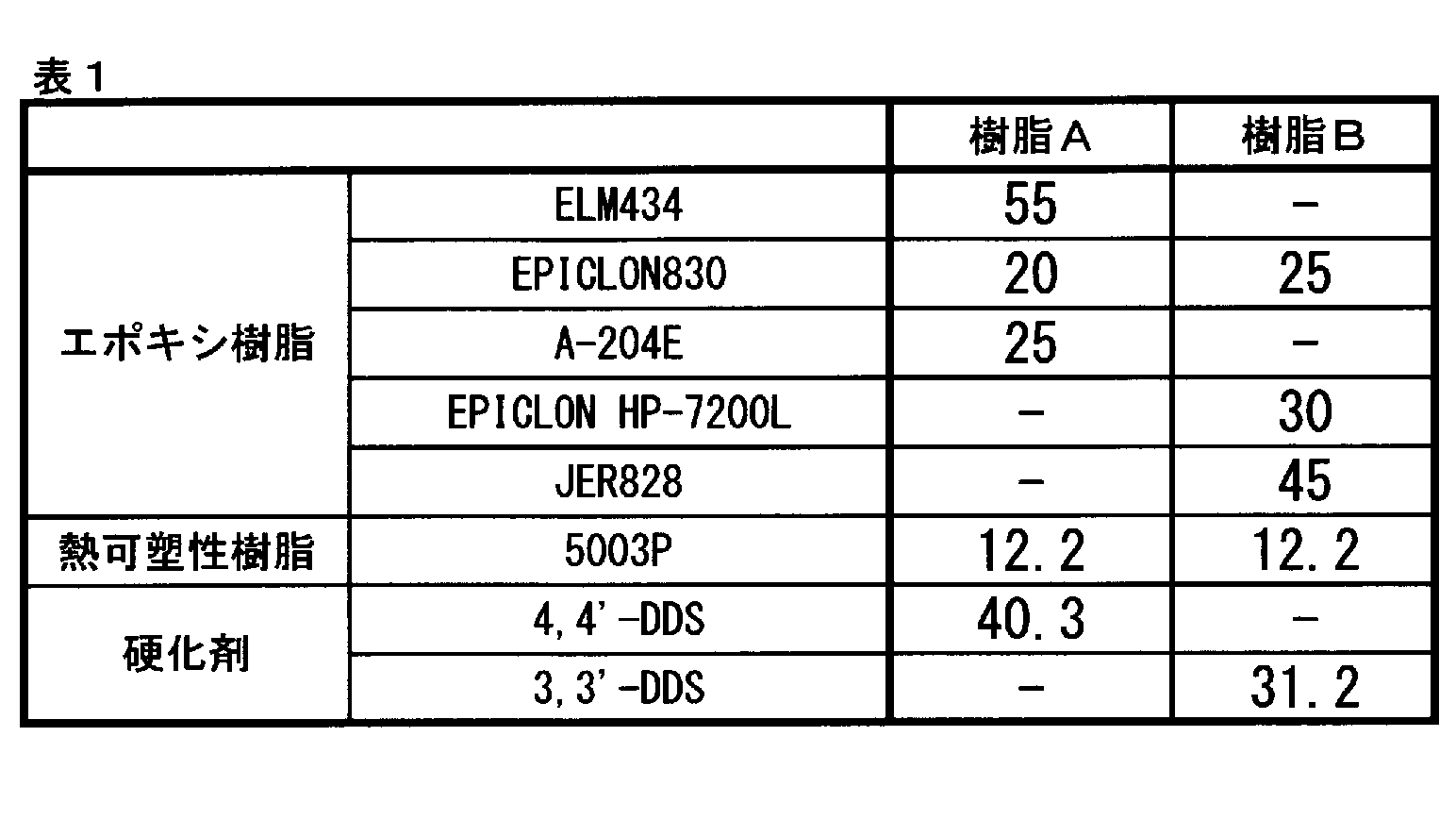
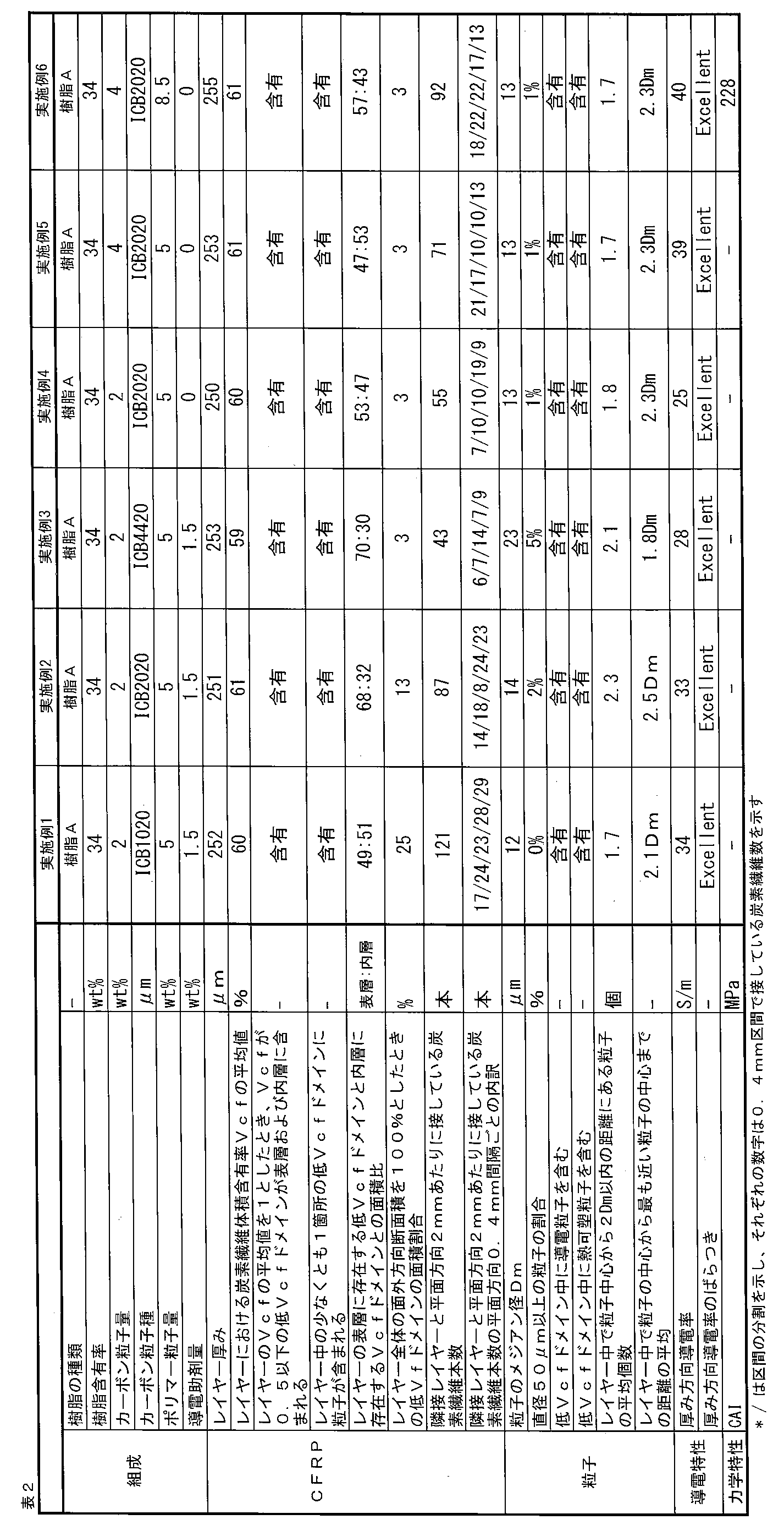
.png)
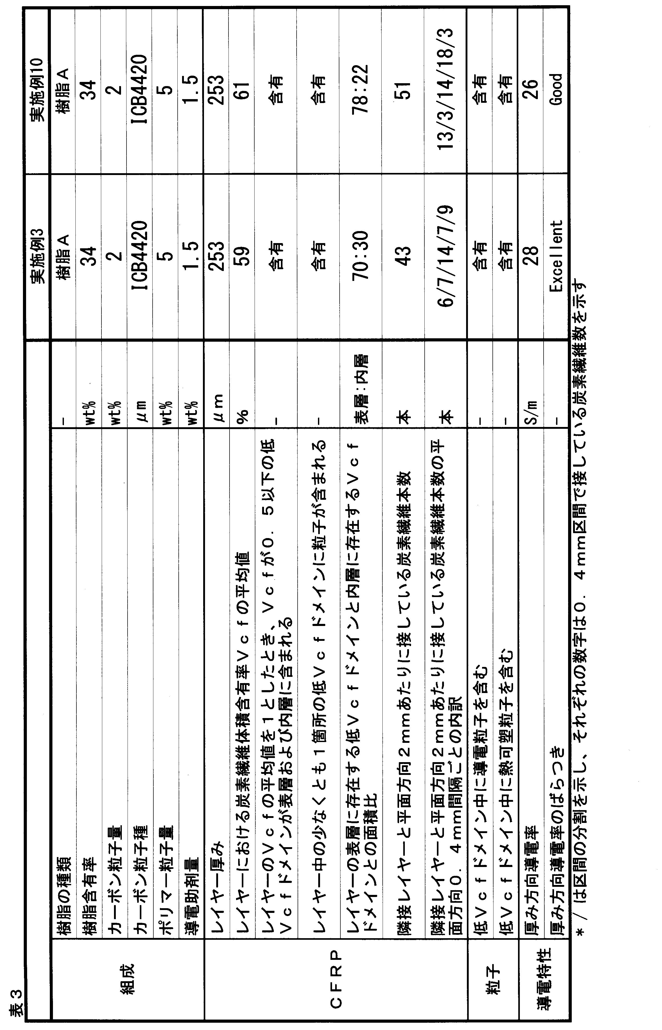
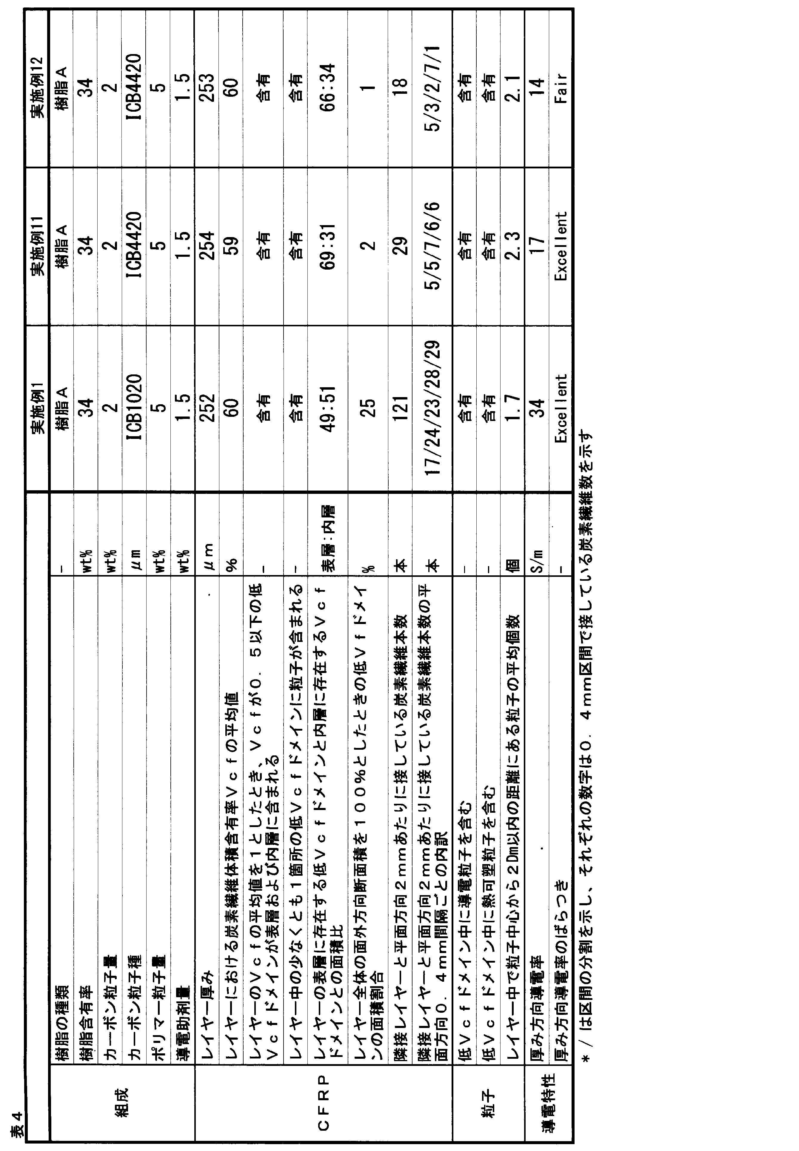
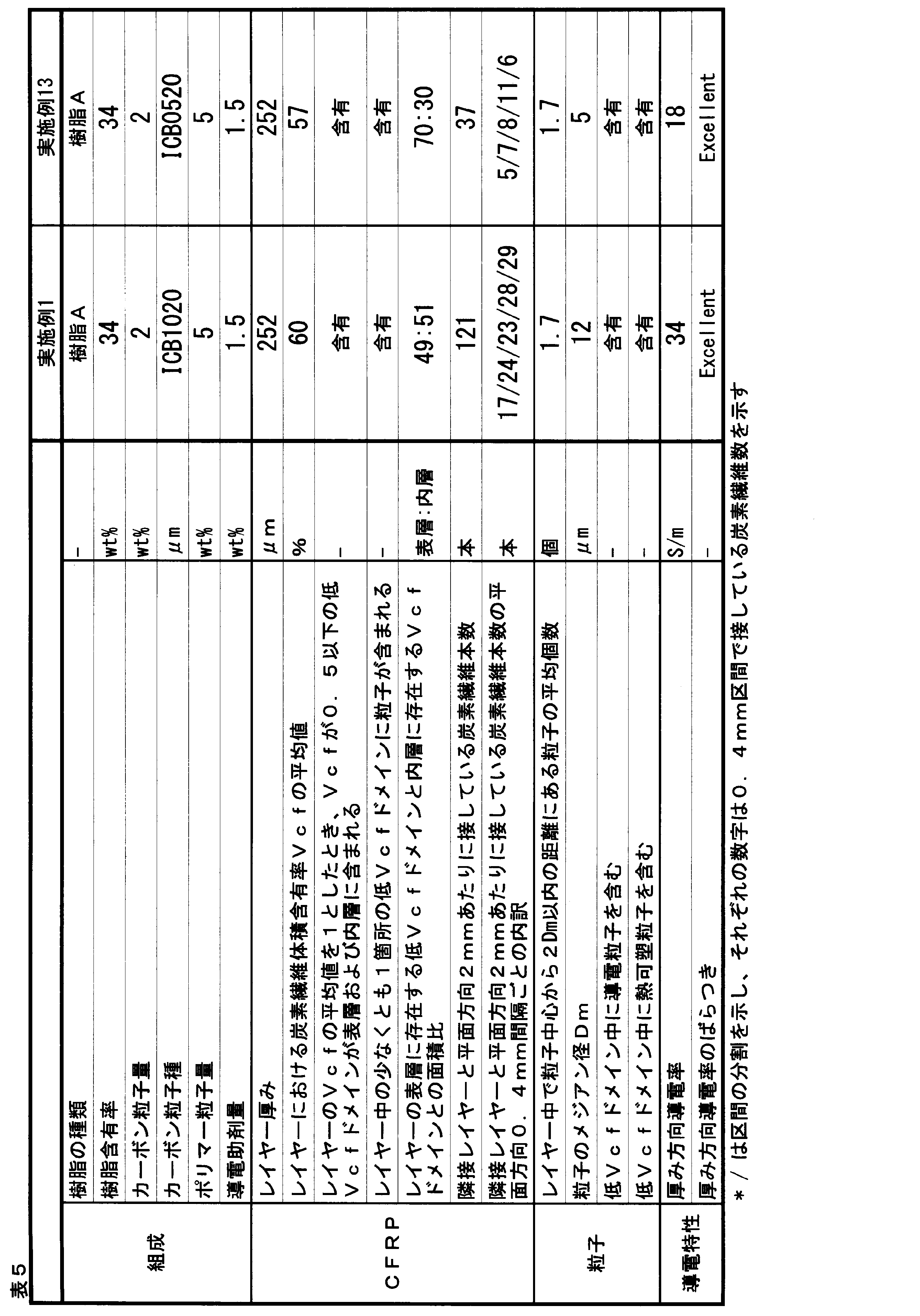
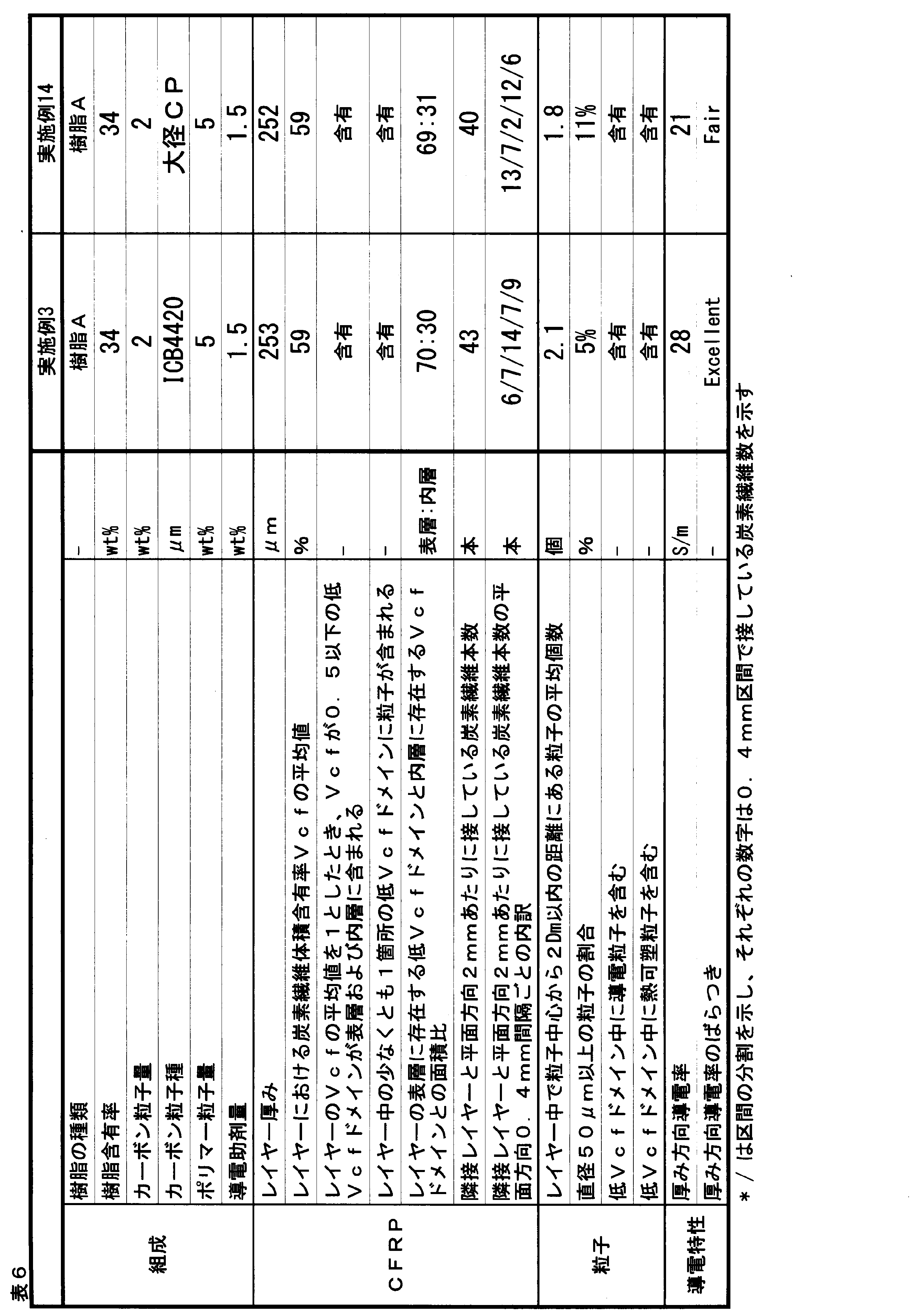
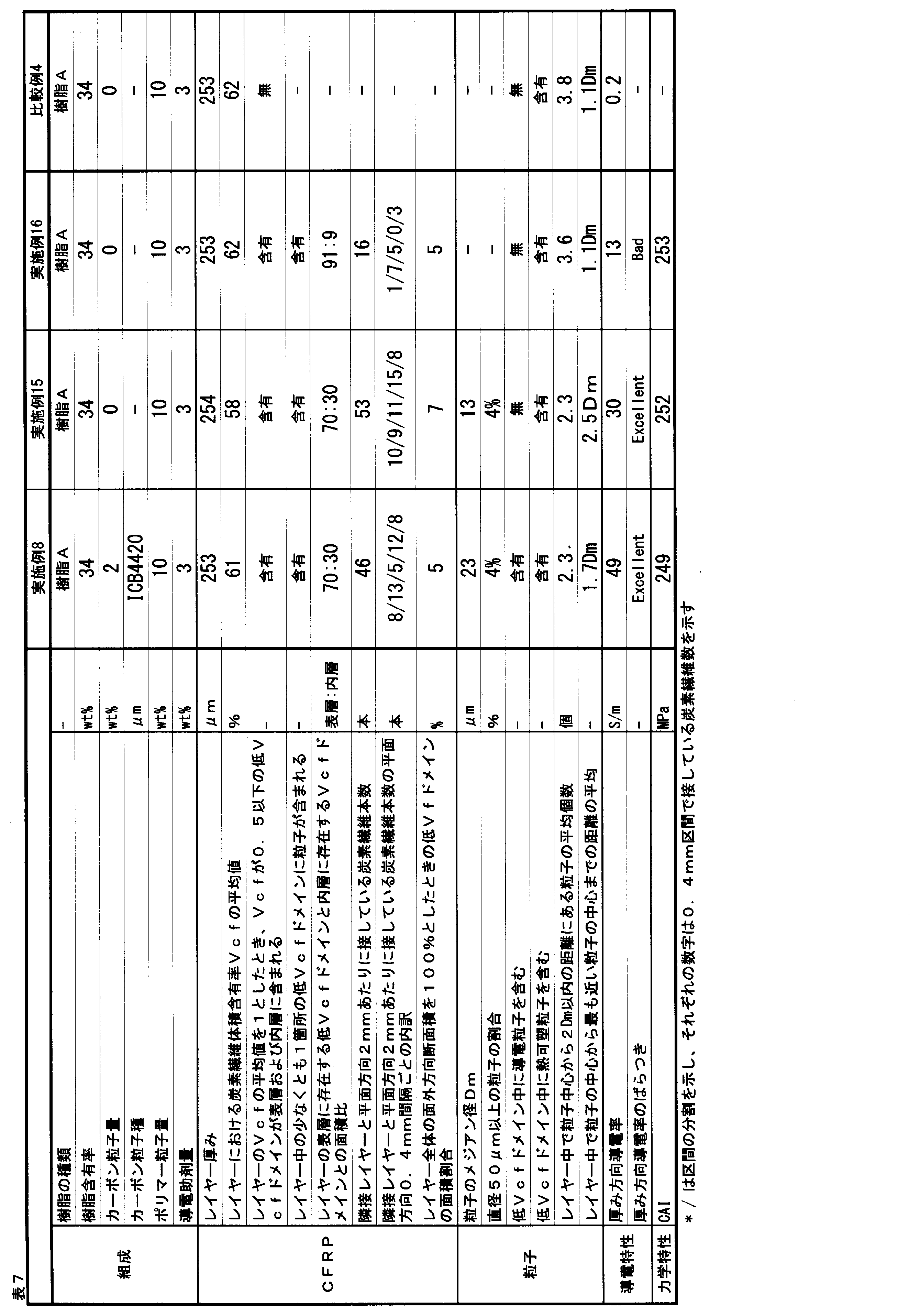
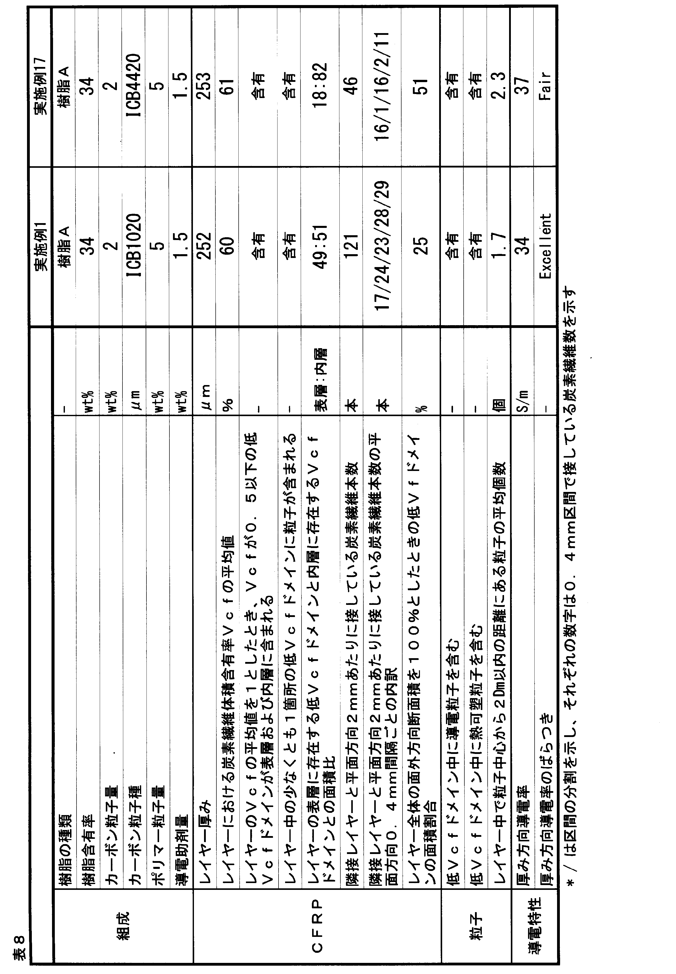
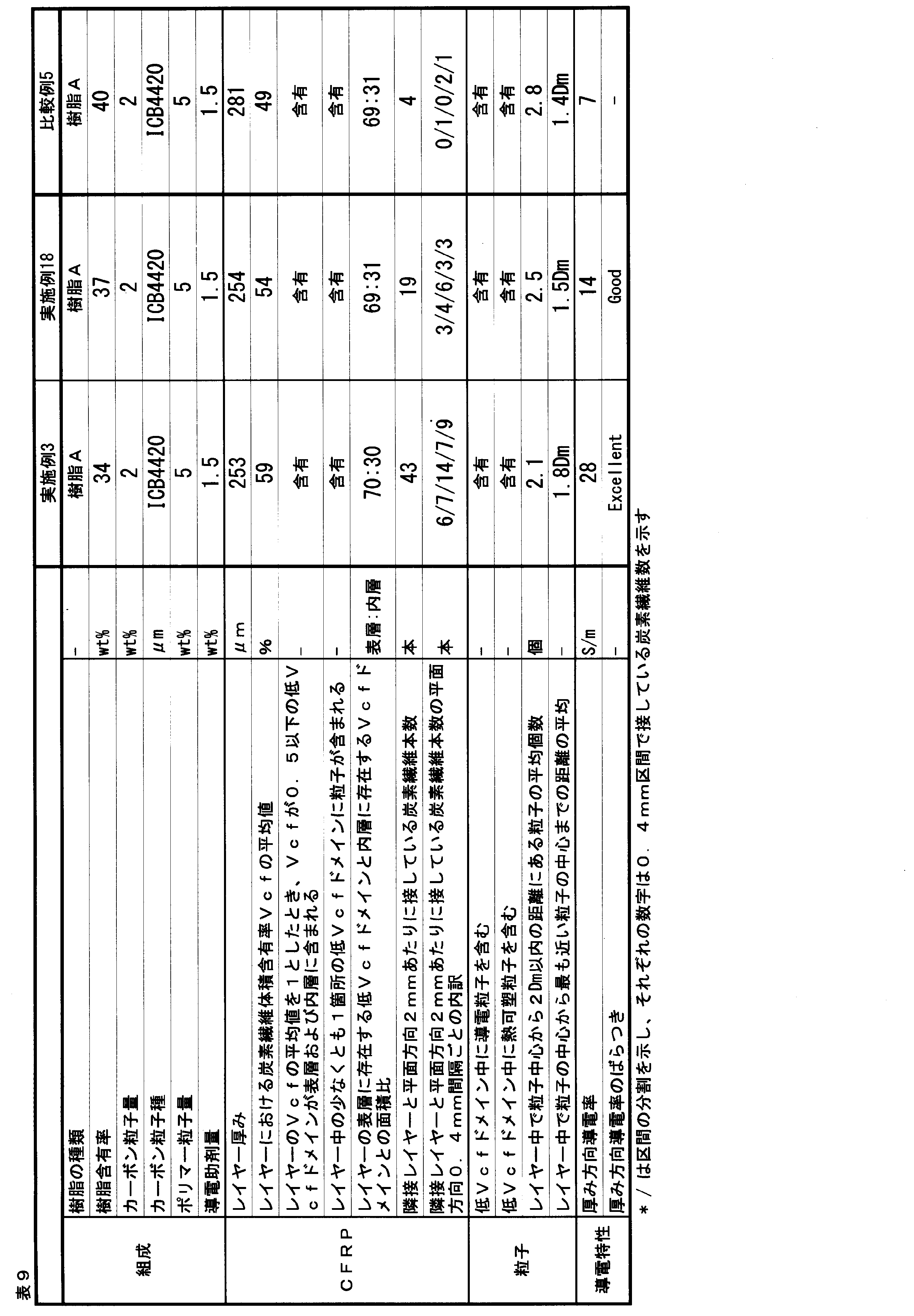

2 炭素繊維層に含浸しているマトリックス樹脂
3、3’ 粒子
20、23、24、25 上側隣接レイヤーとのレイヤー間樹脂層
30、33,34,35 下側隣接レイヤーとのレイヤー間樹脂層
100 繊維配向角度が同一のレイヤー(”特定レイヤー”)
103、104、105 繊維配向角度が同一のレイヤー
110、115 低Vcfドメイン
150、151、152、153、155,156 ”特定レイヤー”の外層
160、161、165 ”特定レイヤー”の内層
200、203、204、205 上側に存在する隣接レイヤー
300、303、304、305 下側に存在する隣接レイヤー
1000 本発明のCFRPの一実施形態
1003 従来の通常のCFRPの一形態
1004 従来の層間強化型のCFRPの一形態
1005 従来の層間強化型のCFRPの一形態
3000 CFRPパネルの上面図
L1、L4 Z軸方向の中間に観察されるレイヤー
L2、L5 Z軸方向の上側に観察される隣接レイヤー
L3、L6 Z軸方向の下側に観察される隣接レイヤー
W1 X軸方向全域長
w11、w12,w13 ”特定レイヤー”をレイヤー平面方向に0.4mmで区切った区間
A1、A1’ 3つのレイヤー全体のVcfの中央値
B1、B1’ レイヤー間樹脂層を定義するためのVcfの閾値
C1、C1’ レイヤー全体のVcfの平均値
D1、D1’ 低Vcfドメインを定義するためのVcfの閾値
E1 表層と内層を区別するための境界厚さ(0点からの4分の1厚みに相当)
F1 表層と内層を区別するための境界厚さ(0点からの4分の3厚みに相当)
I1、I1’ 下側隣接レイヤーとのレイヤー間樹脂層の該当箇所
J1 上側の隣接レイヤーとの境界近傍において、Vcfの最小値を取るポイント
J1’上側隣接レイヤーとのレイヤー間樹脂層の該当箇
K1 ”特定レイヤー”の低Vcfドメインの解析範囲
F1 解析範囲内の拡大図
P1 任意のピクセル
Q1 Vcfを計算する範囲
S1,S2、S4 低Vcfドメイン
S2’、S3’ 低Vcfドメインに存在する粒子の例
S4’ 粒子が存在しない低Vcfドメインの例
Z3、Z6 下側隣接レイヤーとのレイヤー間の境界におけるZ座標
Z2、Z5 上側隣接レイヤーとのレイヤー間の境界におけるZ座標
M1 断面観察用のサンプルカット部
T20、T24、T25 上側隣接レイヤーとの間のレイヤー間樹脂層厚み
T30、T34、T35 下側隣接レイヤーとの間のレイヤー間樹脂層厚み
T100、T104、T105 レイヤーの厚み
Claims (15)
- 炭素繊維が一方向に配列された炭素繊維シートが、多方向に積層され、
マトリックス樹脂が含浸され、硬化されており、
厚み方向導電率が10S/m以上である、炭素繊維強化複合材料において、
該炭素繊維シートが、厚さ方向に連続して炭素繊維の繊維配向角度が同じである領域をレイヤーとしたとき、
(1)~(3)を同時に満たすレイヤー(かかるレイヤーを以下、「特定レイヤー」と称する)を少なくとも1層含み、更に、該特定レイヤー中に少なくとも1箇所の低Vcfドメインが存在し、該低Vcfドメインに粒子が含有される、炭素繊維強化複合材料。
(1)レイヤーの厚みが150μm以上
(2)レイヤーにおける炭素繊維体積含有率Vcfの平均値が50%以上
(3)該Vcfの平均値を1としたとき、Vcfが0.5以下の低Vcfドメインが該特定レイヤーの表層および内層に含まれる。 - 低Vcfドメインが該特定レイヤーの表層および内層に含まれる請求項1に記載の炭素繊維複合材料。
- 前記特定レイヤーの断面をみたとき、表層に存在する低Vcfドメインと内層に存在する低Vcfドメインとの面積比が90:10~10:90である、請求項2に記載の炭素繊維複合材料。
- 前記特定レイヤー全体の面外方向断面の断面積を100%としたとき、
該特定レイヤーの前記低Vcfドメインの面積割合が1%以上50%以下である、請求項1に記載の炭素繊維強化複合材料。 - 前記特定レイヤーに含まれる粒子のメジアン径をDmとしたとき、
該特定レイヤー中のそれぞれの粒子においてその粒子の中心から2Dm以内の距離にある粒子の平均個数が3.5個以下である
請求項1に記載の炭素繊維強化複合材料。 - 前記粒子のメジアン径をDmとしたとき
前記粒子の含まれる特定レイヤー中で該粒子の中心から最も近い粒子の中心までの距離の平均が1.2Dm以上である
請求項1に記載の炭素繊維強化複合材料。 - 前記粒子の真球度が0.9以上である、請求項1に記載の炭素繊維強化複合材料。
- 前記粒子のメジアン径Dmが6μm以上である、請求項1に記載の炭素繊維強化複合材料。
- 含有される粒子のうち、直径50μm以上の粒子の割合が10%以下である、請求項1に記載の炭素繊維強化複合材料。
- 前記粒子の少なくとも1種類が導電粒子である、請求項1に記載の炭素繊維強化複合材料。
- 前記導電粒子がカーボン粒子である、請求項10に記載の炭素繊維強化複合材料。
- 前記粒子の少なくとも1種類がポリマー粒子である、請求項1に記載の炭素繊維強化複合材料。
- 前記ポリマー粒子がポリアミド粒子である、請求項12に記載の炭素繊維強化複合材料。
- 特定レイヤーを構成する炭素繊維と、該特定レイヤーに隣接するレイヤーのうち少なくともひとつのレイヤーに含まれる炭素繊維とが、
特定レイヤー平面方向2mmの区間で5本以上接しており、かつ、
特定レイヤー該2mmの区間を0.4mm間隔でみたとき、全ての0.4mmの区間において少なくとも1本以上接している
請求項1に記載の炭素繊維強化複合材料。 - 請求項1~15のいずれかに記載の炭素繊維強化複合材料からなる構造体であって、
その形状が平板構造体、円筒構造体、箱形構造体、C形構造体、H形構造体、L形構造体、T形構造体、I形構造体、Z形構造体およびハット形構造体から選ばれる、構造体。
Priority Applications (3)
| Application Number | Priority Date | Filing Date | Title |
|---|---|---|---|
| US18/692,513 US20250122347A1 (en) | 2021-10-27 | 2022-10-26 | Carbon fiber-reinforced composite material |
| JP2022566338A JPWO2023074733A1 (ja) | 2021-10-27 | 2022-10-26 | |
| EP22887058.0A EP4424486A4 (en) | 2021-10-27 | 2022-10-26 | CARBON FIBER REINFORCED COMPOSITE MATERIAL |
Applications Claiming Priority (4)
| Application Number | Priority Date | Filing Date | Title |
|---|---|---|---|
| JP2021175395 | 2021-10-27 | ||
| JP2021175396 | 2021-10-27 | ||
| JP2021-175396 | 2021-10-27 | ||
| JP2021-175395 | 2021-10-27 |
Publications (1)
| Publication Number | Publication Date |
|---|---|
| WO2023074733A1 true WO2023074733A1 (ja) | 2023-05-04 |
Family
ID=86157988
Family Applications (1)
| Application Number | Title | Priority Date | Filing Date |
|---|---|---|---|
| PCT/JP2022/039900 Ceased WO2023074733A1 (ja) | 2021-10-27 | 2022-10-26 | 炭素繊維強化複合材料 |
Country Status (4)
| Country | Link |
|---|---|
| US (1) | US20250122347A1 (ja) |
| EP (1) | EP4424486A4 (ja) |
| JP (1) | JPWO2023074733A1 (ja) |
| WO (1) | WO2023074733A1 (ja) |
Cited By (2)
| Publication number | Priority date | Publication date | Assignee | Title |
|---|---|---|---|---|
| WO2025033448A1 (ja) * | 2023-08-08 | 2025-02-13 | 東レ株式会社 | プリプレグ、炭素繊維強化複合材料および構造体 |
| WO2025033447A1 (ja) * | 2023-08-08 | 2025-02-13 | 東レ株式会社 | プリプレグ、炭素繊維強化複合材料および構造体ならびにプリプレグの製造方法 |
Citations (14)
| Publication number | Priority date | Publication date | Assignee | Title |
|---|---|---|---|---|
| JPH01104624A (ja) | 1987-10-16 | 1989-04-21 | Toray Ind Inc | 樹脂微粒子を用いたプリプレグ |
| WO2008018421A1 (fr) | 2006-08-07 | 2008-02-14 | Toray Industries, Inc. | Préimprégné et matériau composite renforcé avec des fibres de carbone |
| WO2011027160A1 (en) | 2009-09-04 | 2011-03-10 | Hexcel Composites Limited | Improvements in composite materials |
| WO2012124450A1 (ja) | 2011-03-17 | 2012-09-20 | 東レ株式会社 | プリプレグ、プリプレグの製造方法および炭素繊維強化複合材料 |
| WO2017110991A1 (ja) | 2015-12-25 | 2017-06-29 | 東レ株式会社 | プリプレグおよびその製造方法 |
| JP2017132932A (ja) * | 2016-01-29 | 2017-08-03 | 東レ株式会社 | プリプレグおよび繊維強化複合材料 |
| WO2017179666A1 (ja) * | 2016-04-13 | 2017-10-19 | 東邦テナックス株式会社 | プリプレグおよび繊維強化複合材料、並びに表面改質強化繊維 |
| WO2018173618A1 (ja) | 2017-03-22 | 2018-09-27 | 東レ株式会社 | プリプレグの製造方法および繊維強化複合材料の製造方法 |
| WO2018173619A1 (ja) | 2017-03-22 | 2018-09-27 | 東レ株式会社 | プリプレグの製造方法および繊維強化複合材料の製造方法 |
| WO2018207728A1 (ja) | 2017-05-12 | 2018-11-15 | 東レ株式会社 | ポリアミド微粒子の製造方法およびポリアミド微粒子 |
| WO2021131740A1 (ja) * | 2019-12-26 | 2021-07-01 | 東レ株式会社 | プリプレグ |
| JP2021172694A (ja) * | 2020-04-21 | 2021-11-01 | 帝人株式会社 | プリプレグ |
| WO2022004586A1 (ja) * | 2020-06-30 | 2022-01-06 | 東レ株式会社 | 繊維強化複合材料およびプリプレグの製造方法 |
| WO2022230800A1 (ja) * | 2021-04-26 | 2022-11-03 | 東レ株式会社 | プリプレグ |
Family Cites Families (1)
| Publication number | Priority date | Publication date | Assignee | Title |
|---|---|---|---|---|
| US10472473B2 (en) * | 2015-05-26 | 2019-11-12 | The Boeing Company | Enhancing z-conductivity in carbon fiber reinforced plastic composite layups |
-
2022
- 2022-10-26 US US18/692,513 patent/US20250122347A1/en active Pending
- 2022-10-26 WO PCT/JP2022/039900 patent/WO2023074733A1/ja not_active Ceased
- 2022-10-26 JP JP2022566338A patent/JPWO2023074733A1/ja active Pending
- 2022-10-26 EP EP22887058.0A patent/EP4424486A4/en active Pending
Patent Citations (15)
| Publication number | Priority date | Publication date | Assignee | Title |
|---|---|---|---|---|
| JPH01104624A (ja) | 1987-10-16 | 1989-04-21 | Toray Ind Inc | 樹脂微粒子を用いたプリプレグ |
| WO2008018421A1 (fr) | 2006-08-07 | 2008-02-14 | Toray Industries, Inc. | Préimprégné et matériau composite renforcé avec des fibres de carbone |
| JP2008231395A (ja) * | 2006-08-07 | 2008-10-02 | Toray Ind Inc | プリプレグおよび炭素繊維強化複合材料 |
| WO2011027160A1 (en) | 2009-09-04 | 2011-03-10 | Hexcel Composites Limited | Improvements in composite materials |
| WO2012124450A1 (ja) | 2011-03-17 | 2012-09-20 | 東レ株式会社 | プリプレグ、プリプレグの製造方法および炭素繊維強化複合材料 |
| WO2017110991A1 (ja) | 2015-12-25 | 2017-06-29 | 東レ株式会社 | プリプレグおよびその製造方法 |
| JP2017132932A (ja) * | 2016-01-29 | 2017-08-03 | 東レ株式会社 | プリプレグおよび繊維強化複合材料 |
| WO2017179666A1 (ja) * | 2016-04-13 | 2017-10-19 | 東邦テナックス株式会社 | プリプレグおよび繊維強化複合材料、並びに表面改質強化繊維 |
| WO2018173618A1 (ja) | 2017-03-22 | 2018-09-27 | 東レ株式会社 | プリプレグの製造方法および繊維強化複合材料の製造方法 |
| WO2018173619A1 (ja) | 2017-03-22 | 2018-09-27 | 東レ株式会社 | プリプレグの製造方法および繊維強化複合材料の製造方法 |
| WO2018207728A1 (ja) | 2017-05-12 | 2018-11-15 | 東レ株式会社 | ポリアミド微粒子の製造方法およびポリアミド微粒子 |
| WO2021131740A1 (ja) * | 2019-12-26 | 2021-07-01 | 東レ株式会社 | プリプレグ |
| JP2021172694A (ja) * | 2020-04-21 | 2021-11-01 | 帝人株式会社 | プリプレグ |
| WO2022004586A1 (ja) * | 2020-06-30 | 2022-01-06 | 東レ株式会社 | 繊維強化複合材料およびプリプレグの製造方法 |
| WO2022230800A1 (ja) * | 2021-04-26 | 2022-11-03 | 東レ株式会社 | プリプレグ |
Non-Patent Citations (7)
| Title |
|---|
| CARBON, no. 168, 1995, pages 157 - 163 |
| I. REVEL ET AL., LECTURE PAPER, INTERNATIONAL CONFERENCE ON LIGHTNING PROTECTION 2016, 2016 |
| K. MIZUKAMI ET AL., JOURNAL OF POLYMER TESTING, vol. 69, 2018, pages 320 - 324 |
| R. B. GREEGOR ET AL.: "Finite Element Simulation and Experimental Analysis of Edge Glow for a Generic, 16-Ply Carbon Fiber Reinforced Plastic Composite Laminate", ICOLSE 15 PAPER, 2015 |
| See also references of EP4424486A4 |
| TORIKAI, KUZE: "Aircraft Structural Design", 2003, JAPAN AERONAUTICAL ENGINEERS' ASSOCIATION |
| X. XU, JOURNAL OF NDT AND E INTERNATIONAL, vol. 94, 2018, pages 79 - 91 |
Cited By (2)
| Publication number | Priority date | Publication date | Assignee | Title |
|---|---|---|---|---|
| WO2025033448A1 (ja) * | 2023-08-08 | 2025-02-13 | 東レ株式会社 | プリプレグ、炭素繊維強化複合材料および構造体 |
| WO2025033447A1 (ja) * | 2023-08-08 | 2025-02-13 | 東レ株式会社 | プリプレグ、炭素繊維強化複合材料および構造体ならびにプリプレグの製造方法 |
Also Published As
| Publication number | Publication date |
|---|---|
| EP4424486A1 (en) | 2024-09-04 |
| US20250122347A1 (en) | 2025-04-17 |
| EP4424486A4 (en) | 2025-11-12 |
| JPWO2023074733A1 (ja) | 2023-05-04 |
Similar Documents
| Publication | Publication Date | Title |
|---|---|---|
| US10549499B2 (en) | Composite materials with high Z-direction electrical conductivity | |
| CN104334327B (zh) | 复合材料 | |
| CN107584843B (zh) | 改进的复合材料 | |
| JP7524904B2 (ja) | 繊維強化複合材料およびプリプレグの製造方法 | |
| JP2011213991A (ja) | 炭素繊維強化複合材料 | |
| WO2023074733A1 (ja) | 炭素繊維強化複合材料 | |
| JP2023106337A (ja) | プリプレグ、プリプレグロール、プリプレグテープ、プリプレグ積層体、炭素繊維強化複合材料および構造体 | |
| US12600109B2 (en) | Carbon fiber-reinforced composite material | |
| WO2023140271A1 (ja) | プリプレグの製造方法、プリプレグテープの製造方法、プリプレグ積層体の製造方法および炭素繊維強化複合材料の製造方法 |
Legal Events
| Date | Code | Title | Description |
|---|---|---|---|
| WWE | Wipo information: entry into national phase |
Ref document number: 2022566338 Country of ref document: JP |
|
| 121 | Ep: the epo has been informed by wipo that ep was designated in this application |
Ref document number: 22887058 Country of ref document: EP Kind code of ref document: A1 |
|
| WWE | Wipo information: entry into national phase |
Ref document number: 18692513 Country of ref document: US |
|
| WWE | Wipo information: entry into national phase |
Ref document number: 2022887058 Country of ref document: EP |
|
| NENP | Non-entry into the national phase |
Ref country code: DE |
|
| ENP | Entry into the national phase |
Ref document number: 2022887058 Country of ref document: EP Effective date: 20240527 |
|
| WWP | Wipo information: published in national office |
Ref document number: 18692513 Country of ref document: US |