WO2023084930A1 - Dispositif de stéréolithographie et procédé de production d'un objet imprimé en 3d - Google Patents
Dispositif de stéréolithographie et procédé de production d'un objet imprimé en 3d Download PDFInfo
- Publication number
- WO2023084930A1 WO2023084930A1 PCT/JP2022/035428 JP2022035428W WO2023084930A1 WO 2023084930 A1 WO2023084930 A1 WO 2023084930A1 JP 2022035428 W JP2022035428 W JP 2022035428W WO 2023084930 A1 WO2023084930 A1 WO 2023084930A1
- Authority
- WO
- WIPO (PCT)
- Prior art keywords
- photocurable resin
- platform
- light
- partition wall
- control unit
- Prior art date
- Legal status (The legal status is an assumption and is not a legal conclusion. Google has not performed a legal analysis and makes no representation as to the accuracy of the status listed.)
- Ceased
Links
Images







Classifications
-
- B—PERFORMING OPERATIONS; TRANSPORTING
- B29—WORKING OF PLASTICS; WORKING OF SUBSTANCES IN A PLASTIC STATE IN GENERAL
- B29C—SHAPING OR JOINING OF PLASTICS; SHAPING OF MATERIAL IN A PLASTIC STATE, NOT OTHERWISE PROVIDED FOR; AFTER-TREATMENT OF THE SHAPED PRODUCTS, e.g. REPAIRING
- B29C64/00—Additive manufacturing, i.e. manufacturing of three-dimensional [3D] objects by additive deposition, additive agglomeration or additive layering, e.g. by 3D printing, stereolithography or selective laser sintering
- B29C64/10—Processes of additive manufacturing
- B29C64/106—Processes of additive manufacturing using only liquids or viscous materials, e.g. depositing a continuous bead of viscous material
- B29C64/124—Processes of additive manufacturing using only liquids or viscous materials, e.g. depositing a continuous bead of viscous material using layers of liquid which are selectively solidified
- B29C64/129—Processes of additive manufacturing using only liquids or viscous materials, e.g. depositing a continuous bead of viscous material using layers of liquid which are selectively solidified characterised by the energy source therefor, e.g. by global irradiation combined with a mask
- B29C64/135—Processes of additive manufacturing using only liquids or viscous materials, e.g. depositing a continuous bead of viscous material using layers of liquid which are selectively solidified characterised by the energy source therefor, e.g. by global irradiation combined with a mask the energy source being concentrated, e.g. scanning lasers or focused light sources
-
- B—PERFORMING OPERATIONS; TRANSPORTING
- B29—WORKING OF PLASTICS; WORKING OF SUBSTANCES IN A PLASTIC STATE IN GENERAL
- B29C—SHAPING OR JOINING OF PLASTICS; SHAPING OF MATERIAL IN A PLASTIC STATE, NOT OTHERWISE PROVIDED FOR; AFTER-TREATMENT OF THE SHAPED PRODUCTS, e.g. REPAIRING
- B29C64/00—Additive manufacturing, i.e. manufacturing of three-dimensional [3D] objects by additive deposition, additive agglomeration or additive layering, e.g. by 3D printing, stereolithography or selective laser sintering
- B29C64/10—Processes of additive manufacturing
- B29C64/106—Processes of additive manufacturing using only liquids or viscous materials, e.g. depositing a continuous bead of viscous material
- B29C64/124—Processes of additive manufacturing using only liquids or viscous materials, e.g. depositing a continuous bead of viscous material using layers of liquid which are selectively solidified
-
- B—PERFORMING OPERATIONS; TRANSPORTING
- B29—WORKING OF PLASTICS; WORKING OF SUBSTANCES IN A PLASTIC STATE IN GENERAL
- B29C—SHAPING OR JOINING OF PLASTICS; SHAPING OF MATERIAL IN A PLASTIC STATE, NOT OTHERWISE PROVIDED FOR; AFTER-TREATMENT OF THE SHAPED PRODUCTS, e.g. REPAIRING
- B29C64/00—Additive manufacturing, i.e. manufacturing of three-dimensional [3D] objects by additive deposition, additive agglomeration or additive layering, e.g. by 3D printing, stereolithography or selective laser sintering
- B29C64/20—Apparatus for additive manufacturing; Details thereof or accessories therefor
- B29C64/245—Platforms or substrates
-
- B—PERFORMING OPERATIONS; TRANSPORTING
- B29—WORKING OF PLASTICS; WORKING OF SUBSTANCES IN A PLASTIC STATE IN GENERAL
- B29C—SHAPING OR JOINING OF PLASTICS; SHAPING OF MATERIAL IN A PLASTIC STATE, NOT OTHERWISE PROVIDED FOR; AFTER-TREATMENT OF THE SHAPED PRODUCTS, e.g. REPAIRING
- B29C64/00—Additive manufacturing, i.e. manufacturing of three-dimensional [3D] objects by additive deposition, additive agglomeration or additive layering, e.g. by 3D printing, stereolithography or selective laser sintering
- B29C64/30—Auxiliary operations or equipment
- B29C64/35—Cleaning
-
- B—PERFORMING OPERATIONS; TRANSPORTING
- B29—WORKING OF PLASTICS; WORKING OF SUBSTANCES IN A PLASTIC STATE IN GENERAL
- B29C—SHAPING OR JOINING OF PLASTICS; SHAPING OF MATERIAL IN A PLASTIC STATE, NOT OTHERWISE PROVIDED FOR; AFTER-TREATMENT OF THE SHAPED PRODUCTS, e.g. REPAIRING
- B29C64/00—Additive manufacturing, i.e. manufacturing of three-dimensional [3D] objects by additive deposition, additive agglomeration or additive layering, e.g. by 3D printing, stereolithography or selective laser sintering
- B29C64/30—Auxiliary operations or equipment
- B29C64/364—Conditioning of environment
-
- B—PERFORMING OPERATIONS; TRANSPORTING
- B33—ADDITIVE MANUFACTURING TECHNOLOGY
- B33Y—ADDITIVE MANUFACTURING, i.e. MANUFACTURING OF THREE-DIMENSIONAL [3D] OBJECTS BY ADDITIVE DEPOSITION, ADDITIVE AGGLOMERATION OR ADDITIVE LAYERING, e.g. BY 3D PRINTING, STEREOLITHOGRAPHY OR SELECTIVE LASER SINTERING
- B33Y10/00—Processes of additive manufacturing
-
- B—PERFORMING OPERATIONS; TRANSPORTING
- B33—ADDITIVE MANUFACTURING TECHNOLOGY
- B33Y—ADDITIVE MANUFACTURING, i.e. MANUFACTURING OF THREE-DIMENSIONAL [3D] OBJECTS BY ADDITIVE DEPOSITION, ADDITIVE AGGLOMERATION OR ADDITIVE LAYERING, e.g. BY 3D PRINTING, STEREOLITHOGRAPHY OR SELECTIVE LASER SINTERING
- B33Y50/00—Data acquisition or data processing for additive manufacturing
- B33Y50/02—Data acquisition or data processing for additive manufacturing for controlling or regulating additive manufacturing processes
-
- B—PERFORMING OPERATIONS; TRANSPORTING
- B33—ADDITIVE MANUFACTURING TECHNOLOGY
- B33Y—ADDITIVE MANUFACTURING, i.e. MANUFACTURING OF THREE-DIMENSIONAL [3D] OBJECTS BY ADDITIVE DEPOSITION, ADDITIVE AGGLOMERATION OR ADDITIVE LAYERING, e.g. BY 3D PRINTING, STEREOLITHOGRAPHY OR SELECTIVE LASER SINTERING
- B33Y70/00—Materials specially adapted for additive manufacturing
- B33Y70/10—Composites of different types of material, e.g. mixtures of ceramics and polymers or mixtures of metals and biomaterials
-
- B—PERFORMING OPERATIONS; TRANSPORTING
- B33—ADDITIVE MANUFACTURING TECHNOLOGY
- B33Y—ADDITIVE MANUFACTURING, i.e. MANUFACTURING OF THREE-DIMENSIONAL [3D] OBJECTS BY ADDITIVE DEPOSITION, ADDITIVE AGGLOMERATION OR ADDITIVE LAYERING, e.g. BY 3D PRINTING, STEREOLITHOGRAPHY OR SELECTIVE LASER SINTERING
- B33Y30/00—Apparatus for additive manufacturing; Details thereof or accessories therefor
Definitions
- the present disclosure relates to a stereolithography apparatus and a method of manufacturing a modeled object.
- liquid photocurable resin is irradiated with light such as ultraviolet light to form a three-dimensional modeled object made of cured resin.
- a predetermined level of a molded object is directed toward a base arranged opposite to the light transmission window through a light transmission window provided on the bottom surface of a liquid tank in which a photocurable resin is stored.
- a stereolithography technique in which a step of lifting up a predetermined height is repeated to stack cured layers to form a desired modeled object.
- the modeled object formed by laminating the cured layers is immersed in the photocurable resin in the liquid tank. For this reason, the irradiated light may cure the excess photocurable resin, and there is room for improvement in terms of molding the modeled object with high accuracy.
- the present disclosure has been made in view of the above, and an object thereof is to provide a stereolithography apparatus and a method for manufacturing a model, which can form a model with high accuracy.
- the stereolithography apparatus includes a modeling tank in which a photocurable resin is stored and a light transmission part provided on the bottom surface, and a light beam passing through the light transmission part.
- a light irradiating section that irradiates light for curing the curable resin, a platform that faces the light transmitting section and can move up and down with respect to the modeling tank, and is formed in a cylindrical shape and cooperates with the platform to form an airtight space.
- an elevation control unit for raising and lowering the partition wall, the platform and the partition wall to form a photocurable resin layer having a predetermined thickness between the bottom surface of the partition wall, the lower surface of the airtight space, and the light transmitting portion; an irradiation control unit that irradiates the photocurable resin layer with light corresponding to the cross-sectional shape of the position from the light irradiation unit to form a cured layer.
- the present embodiment includes a modeling tank that stores a photocurable resin and has a light transmission part provided on the bottom surface, a light irradiation part that irradiates light for curing the photocurable resin through the light transmission part, and a light transmission part. and a platform that can be raised and lowered with respect to the modeling tank, and a platform that can be raised and lowered with respect to the platform, is formed in a cylindrical shape, is arranged outside the platform via an airtight member, and cooperates with the platform. and a partition forming an airtight space.
- a step of forming a thick photocurable resin layer, and forming a cured layer by irradiating the photocurable resin layer with light corresponding to the cross-sectional shape of the target object at a predetermined height position from the light irradiation unit. and the step of lowering the partition relative to the platform by a predetermined thickness are repeatedly performed.
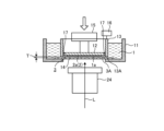
- FIG. 1 is a schematic diagram showing the basic configuration of the optical shaping apparatus according to the first embodiment.
- FIG. 2 is a diagram for explaining the procedure of the method for manufacturing a modeled object according to the first embodiment.
- FIG. 3 is a diagram for explaining the procedure of the method for manufacturing a modeled object according to the first embodiment.
- FIG. 4 is a diagram for explaining the procedure of the method for manufacturing a modeled object according to the first embodiment.
- FIG. 5 is a diagram for explaining the procedure of the method for manufacturing a modeled object according to the first embodiment.
- FIG. 6 is a diagram for explaining the procedure of the method for manufacturing a modeled object according to the first embodiment.
- FIG. 7 is a diagram for explaining the procedure of the method for manufacturing a modeled object according to the first embodiment.
- FIG. 1 is a schematic diagram showing the basic configuration of the optical shaping apparatus according to the first embodiment.
- FIG. 2 is a diagram for explaining the procedure of the method for manufacturing a modeled object according to the first embodiment.
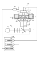
- FIG. 8 is a schematic diagram showing the basic configuration of the optical shaping apparatus according to the second embodiment.
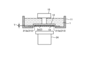
- FIG. 9 is a schematic diagram showing the basic configuration of an optical shaping apparatus according to the third embodiment.
- FIG. 10 is a diagram for explaining the procedure of the method for manufacturing a modeled object according to the third embodiment.
- FIG. 11 is a diagram for explaining the procedure of the method for manufacturing a modeled object according to the third embodiment.
- FIG. 12 is a diagram for explaining the procedure of the method for manufacturing a modeled object according to the third embodiment.
- FIG. 13 is a diagram for explaining the procedure of the method for manufacturing a modeled object according to the third embodiment.
- FIG. 14 is a diagram for explaining the procedure of the method for manufacturing a modeled object according to the third embodiment.
- FIG. 15 is a schematic diagram showing the basic configuration of an optical shaping apparatus according to the fourth embodiment.
- FIG. 16 is a diagram for explaining the operation of the suction mechanism of the optical forming apparatus according to the fourth embodiment;
- an uncured liquid photocurable resin is simply referred to as a photocurable resin.
- a stereolithographic object formed by curing a liquid photocurable resin is called a three-dimensional object or simply a modeled object.
- This three-dimensional modeled object is not limited to a finished product in which all of the plurality of hardened layers to be molded are laminated, but includes an unfinished product in which even hardened layers in the middle are laminated.
- FIG. 1 is a schematic diagram showing the basic configuration of the optical shaping apparatus according to the first embodiment.
- the stereolithography apparatus 10 includes a modeling tank 11, a platform 12, a partition wall 13, a light irradiation section 20, and a control section 30, as shown in FIG. Further, in this embodiment, the stereolithography apparatus 10 includes a chamber 40 and a chamber internal pressure adjustment section 41 .
- the modeling tank 11 has a dish shape with an open upper surface, and is capable of storing the liquid photocurable resin 1 .
- the modeling tank 11 has a light transmission plate (light transmission portion) 14 on the bottom surface.
- the light transmission plate 14 transmits light for curing the photocurable resin 1 .
- the photocurable resin 1 is a raw material for the three-dimensional structure 2, and contains polymerizable compounds such as acrylic compounds and vinyl compounds, for example.
- the photocurable resin 1 preferably contains a polymerization initiator that generates radical species and the like by light irradiation.
- the platform 12 holds the modeled object 2 made of the cured photocurable resin 1 and is arranged above the modeling tank 11 facing the light transmitting plate 14 .
- the platform 12 is formed in a polygonal plate shape such as a disk shape or square plate shape, for example, and is arranged so that its lower surface 12A is substantially parallel to the light transmission plate 14 .
- the platform 12 is connected to a platform lifting mechanism 15 and is provided so as to be able to move up and down with respect to the modeling tank 11 by the operation of the platform lifting mechanism 15 .
- the platform 12 can approach or retreat from the light transmission plate 14 and holds the modeled object 2 formed on the lower surface 12A facing the light transmission plate 14 .
- the partition wall 13 is arranged outside the platform 12 and accommodates the platform 12 and the modeled object 2 inside.
- the partition wall 13 is formed in a tubular shape corresponding to the shape of the platform 12 (a polygonal tubular shape such as a cylindrical shape or a rectangular tubular shape). Further, the partition wall 13 is connected to a partition lifting mechanism 16 and is provided so as to be able to move up and down with respect to the platform 12 by the operation of the partition lifting mechanism 16 . That is, the partition wall 13 can be raised or lowered relative to the platform 12 .
- an airtight member 17 for sealing between the platform 12 and the partition wall 13 is arranged on the outer peripheral edge of the platform 12 .
- the airtight member 17 is an O-ring made of an elastic member such as rubber.
- the airtight member 17 is biased against the inner surface of the partition wall 13 by a restoring force when elastically deformed, and seals between the platform 12 and the partition wall 13 .
- the airtightness between the platform 12 and the partition wall 13 is ensured by the airtight member 17 . Therefore, when the platform 12 and the partition 13 are lowered into the photocurable resin 1, a space 3 (airtight space) is formed by the platform 12 and the partition 13 and the photocurable resin 1.
- the light irradiation unit 20 is arranged below the modeling tank 11, that is, on the side opposite to the platform 12 with the light transmitting plate 14 interposed therebetween.
- the light irradiation unit 20 irradiates the photocurable resin 1 with light L for curing the photocurable resin 1 through the light transmission plate 14 .
- the light L to be irradiated may be any light that can cure the photocurable resin 1, and for example, ultraviolet light or short-wavelength visible light is used.
- the light irradiation unit 20 includes a light source 21 such as an ultraviolet lamp, an image forming element 22, a reflecting mirror 23, a projection lens 24, and the like.
- the light source 21 emits light to irradiate the image forming element 22, and for example, an ultraviolet lamp or the like is used.
- the image forming element 22 modulates according to the shape data of each layer of the modeled object 2 to be formed.
- a liquid crystal device can be used.
- Reflecting mirror 23 reflects the light modulated by image forming element 22 toward projection lens 24 .
- a projection lens 24 forms an image of the light reflected by the reflecting mirror 23 .
- the light irradiation unit 20 is not limited to this, and may be a laser scanning device using a laser light source and a mirror drive, or an optical device using a reflective optical system or a refractive optical system.
- the chamber 40 is a container that accommodates at least the modeling tank 11, the platform 12, the partition wall 13, the light irradiation unit 20, the lift mechanisms 15 and 16, and the like, and seals the internal environment from the outside.
- the chamber internal pressure adjustment unit 41 adjusts the internal pressure of the chamber 40 by introducing gas (for example, air or nitrogen) into the chamber 40 or discharging the gas to the outside of the chamber 40 through the pipe 42 . By finely adjusting the internal pressure of the chamber 40, the position of the lower surface of the space 3 can be freely adjusted.
- the control unit 30 is, for example, an arithmetic processing unit composed of a CPU (Central Processing Unit) or the like, is connected to each unit of the stereolithography apparatus 10, and controls these operations.
- the control unit 30 stores a program related to a manufacturing method for manufacturing the modeled article 2, loads this program into the memory, and executes instructions included in the program.
- the control unit 30 includes an internal memory (not shown), which is used for temporary storage of data such as programs in the control unit 30 .
- the control unit 30 includes an elevation control unit 31 , an irradiation control unit 32 and a chamber internal pressure control unit 33 .
- the elevation control unit 31 controls the height positions of the platform 12 and the partition wall 13 by controlling the operations of the platform elevation mechanism 15 and the partition wall elevation mechanism 16 . That is, the elevation control unit 31 can move the platform 12 and the partition wall 13 up and down in conjunction with the modeling tank 11 and can move the platform 12 up and down relative to the partition wall 13 .
- the lift control unit 31 lifts and lowers the platform 12 and the partition 13 to form a photocurable resin layer having a predetermined thickness between the lower surface of the partition 13 and the lower surface of the space 3 and the light transmission plate 14 .
- the irradiation control unit 32 calculates a light irradiation pattern that indicates the cross-sectional shape of the modeled object at predetermined height increments, controls the light source 21, the image forming element 22, etc., and performs photocuring. irradiate the resin with light. For this reason, the irradiation control unit 32 irradiates the photocurable resin layer between the lower surface of the space 3 and the light transmission plate 14 with light corresponding to the cross-sectional shape of the modeled object at a predetermined height position. A hardened layer having a predetermined thickness can be formed.
- the chamber internal pressure control unit 33 monitors, for example, the position of the lower surface of the space 3 inside the partition wall 13 (liquid surface of the photocurable resin), and adjusts the internal pressure of the chamber 40 according to the result. Therefore, the lower surface of the space 3 can be aligned with the lower surface of the partition wall 13, and the thickness of the photocurable resin layer between the lower surface of the space 3 and the light transmission plate 14 can be defined with high accuracy.
- FIG. 2 schematically show a part of the stereolithography apparatus 10 shown in FIG.
- the elevation control unit 31 adjusts the height positions of the platform 12 and the partition wall 13 so that the lower surface 12A of the platform 12 and the lower surface (bottom surface) 13A of the partition wall 13 are flush with each other.
- the elevation control unit 31 lowers the platform 12 and the partition wall 13, which are arranged higher than the modeling tank 11 in which the photocurable resin 1 is stored, into the modeling tank 11, and the lower surface 13A of the partition wall 13 and the light transmission plate 14 are moved downward.
- the predetermined distance T is set to the thickness of one layer of the cured layer to be molded (for example, about several ⁇ m to 100 ⁇ m).
- a photocurable resin layer 1a having a predetermined thickness T which is the same as the predetermined distance T is formed.
- the irradiation control unit 32 calculates an irradiation pattern indicating the cross-sectional shape of the object 2 at a predetermined height, and corresponds to the cross-sectional shape of the first layer.
- the light L is applied through the light transmission plate 14 to the photocurable resin layer 1a.
- the photocurable resin layer 1a is cured to have the same cross-sectional shape as the first layer.
- the platform 12 holds a hardening layer 2a having a predetermined thickness T, which is the first layer.
- the elevation control unit 31 raises the platform 12 and the partition wall 13 to place them at a position higher than the modeling tank 11, as shown in FIG.
- the elevation control unit 31 lowers the partition wall 13 by a predetermined thickness T relative to the platform 12, as shown in FIG.
- the bottom surface 13A of the partition wall 13 is flush with the bottom surface 2aA of the hardening layer 2a, and a space (airtight space) 3 defined by the platform 12 and the partition wall 13 is formed around the hardening layer 2a.
- the elevation control unit 31 vertically lowers the platform 12 and the partition 13 into the modeling tank 11 until the lower surface 13A of the partition 13 and the light transmission plate 14 become a predetermined distance T.
- the space 3 partitioned by the platform 12 and the partition wall 13 is an airtight space, as shown in FIG. A flexible resin layer 1a is formed.
- the lower surface 3A of the space 3 coincides with the liquid surface of the photocurable resin layer 1a
- the height position of the liquid surface of the photocurable resin layer 1a corresponds to the light of the area stored around the partition wall 13. It may vary depending on the depth and surface area of the curable resin 1 .
- the chamber internal pressure adjusting section 41 shown in FIG. 1 is used to appropriately adjust the height position of the liquid surface of the photocurable resin layer 1a.
- the chamber internal pressure control unit 33 monitors, for example, the position of the liquid surface of the photocurable resin layer 1a inside the partition wall 13, and adjusts the thickness of the photocurable resin layer 1a to a predetermined thickness T according to the result.
- the internal pressure of the chamber 40 is adjusted to .
- the chamber internal pressure control section 33 can lower the lower surface 3A of the space 3 and reduce the thickness of the photocurable resin layer 1a by lowering the chamber internal pressure from the initial state.
- the chamber internal pressure control section 33 can adjust the internal pressure of the chamber 40 in this way, the lower surface 3A of the space 3 can be aligned with the lower surface 13A of the partition wall 13, and the photocurable resin layer 1a can be brought into contact only with the lower surface 2aA of the cured layer 2a. can be done.
- the irradiation control unit 32 irradiates the photocurable resin layer 1a through the light transmission plate 14 with light L corresponding to the cross-sectional shape of the second layer.
- the photocurable resin layer 1a is cured to have the same cross-sectional shape as the second layer, as shown in FIG. molded.
- the photocurable resin layer 1a having a predetermined thickness T is formed between the lower surface 13A of the partition wall 13 and the lower surface 3A of the space 3 and the light transmission plate 14, and the photocurable resin layer 1a is formed. is cured into a predetermined shape, the thickness of the cured layer 2a can be accurately molded, and the modeled object 2 can be accurately molded.
- the space 3 can be provided around the hardening layer 2a that has been molded in advance, the problem that the light L irradiated through the light transmission plate 14 hardens the excess photocurable resin 1 can be avoided. can be prevented.
- the elevation control unit 31 and the irradiation control unit 32 alternately form the photocurable resin layer 1a and the hardened layer 2a to form the n-th layer (n is a natural number) of the hardened layer 2a.
- the modeled object 2 can be molded by laminating the (n+1)-th hardening layer 2a on the .
- the stereolithography apparatus 10 stores the photocurable resin 1 and hardens the photocurable resin 1 through the modeling tank 11 provided with the light transmission plate 14 on the bottom surface and the light transmission plate 14.
- a light irradiation unit 20 that irradiates light L that causes the light to be emitted, a platform 12 that faces the light transmission plate 14 and can be raised and lowered with respect to the modeling tank 11, and a platform 12 that can be raised and lowered with respect to the platform 12 and is formed in a cylindrical shape.
- a partition wall 13 is arranged outside the platform 12 via an airtight member 17 and cooperates with the platform 12 to form an airtight space 3.
- the platform 12 and the partition wall 13 are respectively raised and lowered to move the lower surface 13A of the partition wall 13 and the space 3.
- a lift control unit 31 that forms a photocurable resin layer 1a with a predetermined thickness T between the lower surface 3A and the light transmission plate 14, and light L that corresponds to the cross-sectional shape of the target object 2 at a predetermined height. from the light irradiation unit 20 to the photocurable resin layer 1a to form the cured layer 2a.
- the photocurable resin layer 1a having a predetermined thickness T is formed between the lower surface 13A of the partition wall 13 and the lower surface 3A of the space 3 and the light transmission plate 14, and the photocurable resin layer 1a is formed in a predetermined shape. Since the cured layer 2a is hardened to a high degree of accuracy, the thickness of the hardened layer 2a can be accurately molded, and the modeled object 2 can be accurately molded. In addition, according to this configuration, since the space 3 can be provided around the hardened layer 2a formed in advance, the light L emitted through the light transmission plate 14 hardens the excess photocurable resin 1. can be prevented, and the modeled object 2 can be formed with high accuracy.
- the elevation control unit 31 lowers the platform 12 and the partition wall 13 into the modeling tank 11 in order to lower the partition wall 13 by a predetermined thickness T relative to the platform 12 each time the formation of the hardened layer 2a is completed.
- a photocurable resin layer 1a having a predetermined thickness T can always be formed between the lower surface 13A of the partition wall 13 and the lower surface 3A of the space 3 and the light transmission plate 14. FIG. Therefore, the thickness of the hardened layer 2a can be accurately molded, and the modeled object 2 can be accurately molded.
- the elevation control unit 31 temporarily raises the platform 12 and the partition walls 13 above the photocurable resin 1, so that gas is introduced inside the platform 12 and the partition walls 13. , can form an airtight space. Therefore, the thickness of the hardened layer 2a can be accurately molded, and the modeled object 2 can be accurately molded.
- the elevation control unit 31 and the irradiation control unit 32 alternately form the photocurable resin layer 1a and the hardening layer 2a, stacking a plurality of hardening layers 2a on the platform 12 to form the modeled object 2.
- the modeled object 2 can be molded with high accuracy.
- the stereolithography apparatus 10 includes a chamber 40 that houses at least the modeling tank 11, the platform 12, the partition wall 13, and the light irradiation unit 20, a chamber internal pressure adjustment unit 41 that adjusts the internal pressure of the chamber 40, and the chamber internal pressure adjustment unit 41
- a chamber internal pressure adjustment unit 41 that adjusts the internal pressure of the chamber 40
- the chamber internal pressure adjustment unit 41 By adjusting the internal pressure of the chamber 40, the position of the lower surface 3A of the space 3 can be aligned with the lower surface 13A of the partition wall 13, and the photocurable resin layer 1a can be formed to a predetermined thickness T. can be defined precisely. Therefore, the thickness of the hardened layer 2a can be accurately molded, and the modeled object 2 can be accurately molded.
- FIG. 8 is a schematic diagram showing the basic configuration of the optical shaping apparatus according to the second embodiment.
- the same reference numerals are assigned to the same configurations as those of the above-described embodiment, and the description thereof is omitted.
- the platform 12 and the partition wall 13 work together to form the modeled object 2 in which the cured layer 2a is laminated in the modeling tank 11 in which the photocurable resin 1 is stored.
- a space (airtight space) 3 is provided for housing, and a photocurable resin layer 1a having a predetermined thickness T corresponding to one layer is formed between the lower surface 3A of this space 3 and the light transmission plate 14, the modeled object 2
- the modeled object 2 for example, if there is a difference in height between the lower surface 13A of the partition wall 13 forming the space 3 and the lower surface 2A of the cured molded object 2, the cured molded object 2 and the photocurable resin It is assumed that the layer 1a cannot come into contact with the layer 1a, resulting in a molding defect.
- the controller 130 also includes an elevation controller 31 , an irradiation controller 32 , and an air supply/exhaust controller 133 .
- the air cylinder 50 communicates with the space 3 partitioned by the platform 12 and the partition wall 13 through the hose 51 .
- the air cylinder 50 has a piston in, for example, a cylindrical cylinder body.
- the air supply/exhaust control unit 133 monitors, for example, the position of the liquid surface of the photocurable resin layer 1a inside the partition wall 13, and changes the position of the piston in the axial direction according to the result, thereby adjusting the pressure inside the cylinder.
- a gas is introduced into or discharged from the space 3 .
- the air supply/exhaust controller 133 operates the air cylinder 50 to bring the liquid surface of the photocurable resin layer 1 a into contact with the bottom surface 2 A of the modeled object 2 .
- the elevation control unit 31 and the irradiation control unit 32 alternately form the photocurable resin layer 1a and the cured layer 2a to form the n-th layer (n is a natural number) of the cured layer.
- the modeled object 2 is formed by laminating the (n+1)-th hardened layer 2a on the 2a.
- the supply/exhaust control unit 133 monitors the position of the liquid surface of the photocurable resin layer 1a with a sensor or the like, discharges a predetermined amount of gas in the space 3 by the air cylinder 50, and controls the liquid level of the photocurable resin layer 1a.
- the surface is raised slightly to bring the lower surface 2A of the modeled object 2 already cured and the photocurable resin layer 1a into contact with each other.
- the air supply/exhaust control unit 133 supplies a predetermined amount of gas to the space 3 using the air cylinder 50 to reduce the thickness of the photocurable resin layer 1a to a predetermined thickness T.
- the photocurable resin layer 1a maintains contact with the bottom surface 2A of the modeled object 2 that has already been cured due to surface tension.
- the hardened layer 2a is laminated to form the modeled object 2, so that molding defects are suppressed.
- a modeled object 2 with high accuracy can be formed.
- the stereolithography apparatus 110 stores the photocurable resin 1 and cures the photocurable resin 1 through the modeling tank 11 provided with the light transmission plate 14 on the bottom surface and the light transmission plate 14.
- a light irradiation unit 20 that irradiates the light L for irradiating light L and a light transmission plate 14, which is capable of moving up and down with respect to the modeling tank 11, and holds a modeled object 2 formed by stacking cured layers 2a formed by irradiation of the light L.
- a platform 12, and a partition wall which is formed in a cylindrical shape and arranged outside the platform 12 via an airtight member 17 so as to be able to move up and down with respect to the platform 12, and forms an airtight space 3 in cooperation with the platform 12.
- an irradiation control unit 32 for forming the cured layer 2a by irradiating the photocurable resin layer 1a from the light irradiation unit 20 with the light L corresponding to the cross-sectional shape of the modeled object 2 at a predetermined height.
- the photocurable resin layer 1a having a predetermined thickness T is formed between the lower surface 13A of the partition wall 13 and the lower surface 3A of the space 3 and the light transmission plate 14, and the photocurable resin layer 1a is formed in a predetermined shape. Since the cured layer 2a is hardened to a high degree of accuracy, the thickness of the hardened layer 2a can be accurately molded, and the modeled object 2 can be accurately molded. In addition, according to this configuration, since the space 3 can be provided around the hardened layer 2a formed in advance, the light L emitted through the light transmission plate 14 hardens the excess photocurable resin 1. can be prevented, and the modeled object 2 can be formed with high accuracy.
- the air cylinder 50 for supplying and exhausting gas to the space 3 partitioned by the platform 12 and the partition wall 13 since the air cylinder 50 for supplying and exhausting gas to the space 3 partitioned by the platform 12 and the partition wall 13 is provided, the liquid surface height of the photocurable resin layer 1a can be adjusted, The contact state between the curable resin layer 1a and the lower surface 2A of the modeled object 2 that has already been cured is maintained. Therefore, it is possible to mold the model 2 with high accuracy while suppressing molding defects.
- the elevation control unit 31, the air supply/exhaust control unit 133, and the irradiation control unit 32 control the formation of the photocurable resin layer 1a, the contact between the liquid surface of the photocurable resin layer 1a and the lower surface 2A of the modeled object 2, By repeatedly performing the formation of the hardened layer 2a, molding defects can be suppressed and the modeled object 2 can be formed with high accuracy.
- FIG. 9 is a schematic diagram showing the basic configuration of an optical shaping apparatus according to the third embodiment.
- the same reference numerals are assigned to the same configurations as those of the above-described embodiment, and the description thereof is omitted.
- the platform 12 and the partition wall 13 work together to form the modeled object 2 in which the cured layer 2a is laminated in the modeling tank 11 in which the photocurable resin 1 is stored.
- An accommodation space (airtight space) 3 is provided, and a photocurable resin layer 1a having a predetermined thickness T corresponding to one layer is formed between the lower surface 3A of this space 3 and the light transmission plate 14.
- FIG. 1 it is necessary to lower the partition wall 13 by a predetermined thickness T with respect to the platform 12 each time the hardened layer 2a is formed.
- the predetermined thickness T is set to, for example, about several ⁇ m, a problem is assumed in that a precise lifting mechanism is required.
- the stereolithography apparatus 210 includes a modeling tank 11, a platform 12, a light irradiation section 20, and a control section 230, as shown in FIG.
- the control unit 230 also includes an elevation control unit 231 and an irradiation control unit 232 .
- the stereolithography apparatus 210 has a configuration in which a cylindrical partition wall 213 is formed around the modeled object 2 on the platform 12 together with the modeled object 2 instead of providing the partition wall as an apparatus configuration. ing.
- the platform 12 cooperates with the molded partition wall 213 to form the space (airtight space) 3 .
- the elevation control unit 231 also controls the height position of the platform 12 by controlling the operation of the platform elevation mechanism 15 .
- the elevation control unit 231 raises and lowers the platform 12 on which the partition walls 213 are formed to form a photocurable resin layer having a predetermined thickness between the bottom surface of the partition walls 213 and the lower surface of the space 3 and the light transmission plate 14 .
- the irradiation control unit 232 calculates a light irradiation pattern indicating the cross-sectional shape of the modeled object 2 and the partition wall 213 at predetermined height increments, and controls the light source 21, the image forming element 22, and the like. Then, the photocurable resin is irradiated with light. The irradiation control unit 232 irradiates the photocurable resin layer between the lower surface of the space 3 and the light transmission plate 14 with light corresponding to each cross-sectional shape of the modeled object 2 and the partition wall 213 at a predetermined height position. can form a hardened layer having a predetermined thickness.
- FIG. 10 schematically show a part of the stereolithography apparatus 10 shown in FIG.
- the elevation control unit 231 lowers the platform 12, which is arranged higher than the modeling tank 11 in which the photocurable resin 1 is stored, into the modeling tank 11, and the lower surface 12A of the platform 12 and the light source 12 move downward. It is arranged at a position where a predetermined distance T is provided between it and the transmission plate 14 . In this case, between the platform 12 and the light transmitting plate 14, a photocurable resin layer 1a having a predetermined thickness T which is the same as the predetermined distance T is formed.
- the irradiation control unit 232 determines the cross section of the object 2 and the partition wall 213 at a predetermined height. An irradiation pattern indicating the shape is calculated, and light L corresponding to the cross-sectional shape of the modeled object 2 and the first layer of the partition wall 213 is applied through the light transmission plate 14 to the photocurable resin layer 1a. As a result, the photocurable resin layer 1a is cured into the same cross-sectional shape as the first layer of the modeled object 2 and the partition wall 213 . Therefore, as shown in FIG. 11, the platform 12 holds hardened layers 2a and 213a each having a predetermined thickness T, which are the first layers of the modeled object 2 and the partition walls 213, respectively.
- the elevation control unit 231 raises the platform 12 to temporarily place it at a position higher than the modeling tank 11, as shown in FIG.
- the hardened layer 2a of the modeled object 2 and the hardened layer 213a of the partition wall 213 are formed to have a predetermined thickness T and the same height. Therefore, the lower surface 2aA of the hardened layer 2a of the modeled object 2 and the lower surface 213aA of the hardened layer 213a of the partition wall 213 are flush with each other, and the platform 12 and the partition wall 213 ( A space (airtight space) 3 defined by the hardening layer 213a) is formed.
- the elevation control unit 231 vertically lowers the platform 12 into the modeling tank 11 until the distance T between the lower surface 213A of the partition wall 213 and the light transmission plate 14 becomes a predetermined distance.
- the space 3 partitioned by the platform 12 and the partition wall 213 is an airtight space. Therefore, as shown in FIG. A flexible resin layer 1a is formed.
- the irradiation control unit 232 irradiates the photocurable resin layer 1a through the light transmission plate 14 with the light L corresponding to the cross-sectional shape of the modeled object 2 and the second layer of the partition wall 213 .
- the photocurable resin layer 1a is cured into the same cross-sectional shape as the second layer, and the second layer having a predetermined thickness T is laminated on the first layer to form the cured layer 2a, 213a is molded.
- the photocurable resin layer 1a having a predetermined thickness T is formed between the lower surface 213aA of the partition wall 213 and the lower surface 3A of the space 3 molded together with the modeled object 2 and the light transmission plate 14. Then, the photocurable resin layer 1a is cured into a predetermined shape. Therefore, the thicknesses of the hardened layers 2a and 213a of the modeled object 2 and the partition wall 213 can be formed with high precision, and the modeled object 2 can be formed with high precision.
- the space 3 can be provided around the hardening layer 2a that has been molded in advance, the problem that the light L irradiated through the light transmission plate 14 hardens the excess photocurable resin 1 can be avoided. can be prevented. Further, in this embodiment, since the partition 213 is molded together with the object 2, there is no need to separately provide a partition around the platform 12, and the configuration of the stereolithography apparatus 210 can be simplified.
- the elevation control unit 231 and the irradiation control unit 232 alternately form the photocurable resin layer 1a and the hardened layers 2a and 213a of the modeled object 2 and the partition wall 213 to form the n-th layer
- the molded object 2 and the partition wall 213 can be formed by laminating the (n+1)-th hardened layer 2a, 213a on the hardened layer 2a, 213a (where n is a natural number).
- the stereolithography apparatus 210 stores the photocurable resin 1, and cures the photocurable resin 1 through the modeling tank 11 having the light transmission plate 14 on the bottom surface and the light transmission plate 14.
- a light irradiation unit 20 that irradiates the light L that causes the light L to oppose the light transmission plate 14 and is capable of moving up and down with respect to the modeling tank 11 .
- a platform 12 that holds a molded cylindrical partition 213 and cooperates with the partition 213 to form an airtight space 3;
- a lift controller 231 that forms a photocurable resin layer 1a having a predetermined thickness T between itself and the plate 14, and a light irradiation unit 20 that emits light L corresponding to a cross-sectional shape of a predetermined height in the modeled object 2 and partition walls 213.
- an irradiation control unit 232 for forming the respective cured layers 2a and 213a by irradiating the photocurable resin layer 1a.
- the photocurable resin layer 1a having a predetermined thickness T is formed between the lower surface 213aA of the partition wall 213 and the lower surface 3A of the space 3 molded together with the modeled object 2 and the light transmission plate 14.
- the photocurable resin layer 1a is cured into a predetermined shape. Therefore, the thicknesses of the hardened layers 2a and 213a of the modeled object 2 and the partition wall 213 can be formed with high precision, and the modeled object 2 can be formed with high precision.
- the space 3 can be provided around the hardening layer 2a that has been molded in advance, the problem that the light L irradiated through the light transmission plate 14 hardens the excess photocurable resin 1 can be avoided. can be prevented.
- the partition 213 is molded together with the object 2, there is no need to separately provide a partition around the platform 12, and the configuration of the stereolithography apparatus 210 can be simplified.
- the elevation control unit 231 temporarily raises the platform 12 to above the photocurable resin 1, so that gas is trapped inside the partition wall 213 formed on the platform 12. can be introduced to form an airtight space. Therefore, the thickness of the hardened layers 2a and 213a can be formed with high accuracy, and the modeled object 2 can be formed with high accuracy.
- the elevation control unit 231 and the irradiation control unit 232 alternately form the photocurable resin layer 1a and the hardened layers 2a and 213a, and laminate the hardened layers 2a and 213a on the platform 12, respectively. Since the modeled object 2 and the partition wall 213 are formed in this manner, the modeled object 2 can be accurately formed while simplifying the device configuration of the stereolithography apparatus 210 .
- the modeled object 2 can be easily molded with high accuracy.
- FIG. 15 is a schematic diagram showing the basic configuration of an optical shaping apparatus according to the fourth embodiment.
- FIG. 16 is a diagram for explaining the operation of the suction mechanism of the optical forming apparatus according to the fourth embodiment; The same reference numerals are assigned to the same configurations as those of the above-described embodiment, and the description thereof is omitted.
- a modeled object in which a hardening layer 2a is laminated in a modeling tank 11 in which a photocurable resin 1 is stored by cooperation of a platform 12 and a partition wall 13. 2 is provided, and a photocurable resin layer 1a having a predetermined thickness T corresponding to one layer is formed between the lower surface 3A of this space 3 and the light transmission plate 14.
- the object 2 can be molded with high precision, for example, if uncured or semi-cured photo-curing resin remains in the modeled object 2 that has been previously cured, the remaining uncured resin will be difficult to cure when the next cured layer is cured. A problem is assumed in which the photo-curing resin itself hardens together, making it impossible to perform modeling with high accuracy.
- the stereolithography apparatus 310 includes a modeling tank 11, a platform 12, a light irradiation section 20, a suction mechanism 60, and a control section 330, as shown in FIG.
- the controller 330 also includes an elevation controller 231 , an irradiation controller 232 , and a suction controller 333 .
- the suction mechanism 60 generates a negative pressure to suck and remove uncured photocurable resin adhering to the modeled object 2 .
- the suction mechanism 60 includes a dish portion 61 with an open upper surface, a suction portion 62 connected to the dish portion 61 via a hose 63 to generate a negative pressure in the dish portion 61, and a and a moving mechanism 64 for moving the portion 61, for example, in the horizontal direction.
- the stereolithography apparatus 310 has a cylindrical structure around the object 2 on the platform 12 instead of providing a partition as an apparatus configuration. It is configured to mold the partition wall 313 .
- the platform 12 forms a space (airtight space) 3 in cooperation with a molded partition wall 313 .
- the partition wall 313 is formed integrally with the modeled object 2 .
- the procedures for molding these modeled objects 2 and partition walls 313 are the same as those described in the third embodiment. Since the partition wall 313 is integrated with the target object 2, it is necessary to separate the partition wall 313 from the object 2 at the end.
- the plate portion 61 of the suction mechanism 60 is formed to have the same size as the partition wall 313.
- the partition wall 313 is sandwiched between the platform 12 and the plate portion 61 .
- the partition 313 is formed integrally with the modeled object 2 , so the modeled object 2 is supported by the platform 12 and the plate portion 61 via the partition 313 . Therefore, the partition wall 313 also functions as a support that supports the modeled object 2 .
- the stereolithography apparatus 310 stores the photocurable resin 1 and hardens the photocurable resin 1 through the modeling tank 11 having the light transmission plate 14 on the bottom surface and the light transmission plate 14.
- a light irradiation unit 20 that irradiates the light L that causes the light L to oppose the light transmission plate 14 and is capable of moving up and down with respect to the modeling tank 11 .
- the platform 12 that holds the cylindrical partition wall 313 to be molded and cooperates with the partition wall 313 to form the airtight space 3, and the uncured photocurable resin 70 adhering to the modeled object 2 are removed by suction.
- a suction mechanism 60 an elevation controller 231 for raising and lowering the platform 12 to form a photocurable resin layer 1a having a predetermined thickness T between the bottom surface 313A of the partition wall 313 and the lower surface 3A of the space 3 and the light transmission plate 14; an irradiation control unit 232 that irradiates the photocurable resin layer 1a from the light irradiation unit 20 with light L corresponding to a cross-sectional shape of a predetermined height in the modeled object 2 and the partition wall 313 to form an integral cured layer; and a suction control unit 333 that is arranged below the platform 12 and operates the suction mechanism 60 when the platform 12 is positioned above the photocurable resin 1 .
- the photocurable resin layer 1a having a predetermined thickness T is formed between the lower surface 313A of the partition wall 313 and the lower surface 3A of the space 3 and the light transmission plate 14, and the photocurable resin layer 1a is formed in a predetermined shape. Therefore, the thickness of each cured layer of the modeled object 2 and the partition walls 313 can be accurately formed, and the modeled object 2 can be formed with high accuracy.
- the space 3 can be provided around the cured layer of the molded object 2 that has been previously molded, the light L emitted through the light transmission plate 14 removes the excess photocurable resin 1. It is possible to prevent the problem of hardening, and it is possible to form the modeled object 2 with high accuracy.
- a suction mechanism 60 is arranged below the platform 12 to suck and remove the uncured photo-curing resin 70 adhering to the modeled object 2. Since it is activated, the uncured photocurable resin 70 adhering to the modeled object 2 is prevented from being separately cured, and the modeled object 2 can be molded with high accuracy.
- the partition wall 313 is formed integrally with the modeled object 2, is clamped between the plate portion 61 of the suction mechanism 60 and the platform 12 during operation of the suction mechanism 60, and functions as a support for supporting the modeled object 2. Therefore, it is possible to easily prevent the object 2 from detaching from the platform 12 at least during the suction operation.
- the suction mechanism 60 has a plate portion 61 with an open upper surface, and the plate portion 61 contacts the lower surface 313A of the partition wall 313 to form a closed space.
- a negative pressure can be applied, and the uncured photocurable resin 70 adhering to the modeled object 2 can be easily sucked and removed.
- the elevation control unit 231, the irradiation control unit 232, and the suction control unit 333 repeatedly perform the formation of the photocurable resin layer 1a, the formation of the cured layer, and the suction of the uncured photocurable resin 70, Since the modeled object 2 and the partition walls 313 are formed by laminating a plurality of hardened layers on the platform 12, the modeled object 2 can be accurately formed while simplifying the device configuration of the stereolithography apparatus 310.
- the stereolithography apparatus and method for manufacturing a model according to the present invention have been described so far, they may be implemented in various different forms other than the above-described embodiments. Also, the configurations of these embodiments may be combined as appropriate.
- the chamber 40, the chamber internal pressure adjustment unit 41, and the chamber internal pressure control unit 33 in the first embodiment may be combined with the stereolithography apparatus according to the second to fourth embodiments, or the air cylinder in the second embodiment. 50 and the air supply/exhaust control unit 133 may be combined with the optical shaping apparatus according to the first, third, and fourth embodiments.
- the suction mechanism 60 and the suction control unit 333 in the fourth embodiment may be combined with the stereolithography apparatuses according to the first to third embodiments.
- each component of the illustrated stereolithography apparatus is functionally conceptual, and does not necessarily have to be physically configured as illustrated.
- the specific form of each device is not limited to the illustrated one, and all or part of it may be functionally or physically distributed or integrated in arbitrary units according to the processing load and usage conditions of each device.
- the configuration of the control unit of the stereolithography apparatus is implemented by, for example, a program loaded into the memory as software.
- a program loaded into the memory as software.
- functional blocks realized by cooperation of these hardware or software have been described. That is, these functional blocks can be realized in various forms by hardware only, software only, or a combination thereof.
- the stereolithography apparatus and the stereolithography method of the present embodiment are used in stereolithography technology for forming a three-dimensional object made of cured resin by irradiating a liquid photocurable resin with light such as ultraviolet rays. can do.
Landscapes
- Engineering & Computer Science (AREA)
- Chemical & Material Sciences (AREA)
- Materials Engineering (AREA)
- Manufacturing & Machinery (AREA)
- Optics & Photonics (AREA)
- Physics & Mathematics (AREA)
- Mechanical Engineering (AREA)
- Civil Engineering (AREA)
- Structural Engineering (AREA)
- Composite Materials (AREA)
- Ceramic Engineering (AREA)
- Health & Medical Sciences (AREA)
- Environmental & Geological Engineering (AREA)
- Toxicology (AREA)
Abstract
Le dispositif de stéréolithographie (10) comprend : un réservoir de moulage (11) pourvu d'une plaque de transmission de lumière (14) sur la surface inférieure, une résine photodurcissable (1) étant stockée à l'intérieur ; une unité d'émission de lumière (20) servant à émettre de la lumière (L) en vue de durcir la résine photodurcissable (1) ; une plateforme (12) qui peut être levée et abaissée par rapport au réservoir de moulage (11) ; une paroi de séparation (13) formée dans une forme cylindrique et formant un espace étanche à l'air (3) en collaboration avec la plateforme (12) ; une unité de commande d'élévation / d'abaissement (31) servant à former une couche de résine photodurcissable d'une épaisseur prédéterminée entre la surface inférieure de la paroi de séparation (13) et la surface inférieure de l'espace (3) et la plaque de transmission de lumière (14) ; et une unité de commande d'émission (32) servant à exposer la couche de résine photodurcissable à de la lumière (L) correspondant à la forme en section transversale d'un objet imprimé en 3D (2) à une position de hauteur prédéterminée pour former une couche durcie.
Priority Applications (3)
| Application Number | Priority Date | Filing Date | Title |
|---|---|---|---|
| EP22892431.2A EP4410519B1 (fr) | 2021-11-15 | 2022-09-22 | Dispositif de stéréolithographie et procédé de production d'un objet imprimé en 3d |
| CN202280067823.9A CN118076473A (zh) | 2021-11-15 | 2022-09-22 | 光造形装置以及造形物的制造方法 |
| US18/632,350 US20240269920A1 (en) | 2021-11-15 | 2024-04-11 | Stereo lithography apparatus and method of manufacturing modeling object |
Applications Claiming Priority (8)
| Application Number | Priority Date | Filing Date | Title |
|---|---|---|---|
| JP2021185926A JP7797837B2 (ja) | 2021-11-15 | 2021-11-15 | 光造形装置および造形物の製造方法 |
| JP2021185950A JP7786141B2 (ja) | 2021-11-15 | 2021-11-15 | 光造形装置および造形物の製造方法 |
| JP2021185927A JP7797838B2 (ja) | 2021-11-15 | 2021-11-15 | 光造形装置および造形物の製造方法 |
| JP2021-185926 | 2021-11-15 | ||
| JP2021-185927 | 2021-11-15 | ||
| JP2021185879A JP7797835B2 (ja) | 2021-11-15 | 2021-11-15 | 光造形装置および造形物の製造方法 |
| JP2021-185879 | 2021-11-15 | ||
| JP2021-185950 | 2021-11-15 |
Related Child Applications (1)
| Application Number | Title | Priority Date | Filing Date |
|---|---|---|---|
| US18/632,350 Continuation US20240269920A1 (en) | 2021-11-15 | 2024-04-11 | Stereo lithography apparatus and method of manufacturing modeling object |
Publications (1)
| Publication Number | Publication Date |
|---|---|
| WO2023084930A1 true WO2023084930A1 (fr) | 2023-05-19 |
Family
ID=86335461
Family Applications (1)
| Application Number | Title | Priority Date | Filing Date |
|---|---|---|---|
| PCT/JP2022/035428 Ceased WO2023084930A1 (fr) | 2021-11-15 | 2022-09-22 | Dispositif de stéréolithographie et procédé de production d'un objet imprimé en 3d |
Country Status (3)
| Country | Link |
|---|---|
| US (1) | US20240269920A1 (fr) |
| EP (1) | EP4410519B1 (fr) |
| WO (1) | WO2023084930A1 (fr) |
Citations (4)
| Publication number | Priority date | Publication date | Assignee | Title |
|---|---|---|---|---|
| JP2017523925A (ja) * | 2014-08-01 | 2017-08-24 | ベゴ・ブレーマー・ゴルトシュレーゲライ・ヴィルヘルム・ヘルプスト・ゲゼルシャフト・ミット・ベシュレンクテル・ハフツング・ウント・コムパニー・コマンディットゲゼルシャフトBEGO Bremer GoldschlaegereiWilh.Herbst GmbH & Co.KG | 容器アセンブリを有する光造形装置 |
| EP3354442A1 (fr) * | 2017-01-25 | 2018-08-01 | Smart3D.net di Dotta Andrea E Gie' Andrea SNC | Appareil et procédé de production d'objets par stéréolithographie |
| JP2020062841A (ja) | 2018-10-18 | 2020-04-23 | キヤノン株式会社 | 三次元造形装置および三次元造形方法 |
| JP2020066236A (ja) * | 2018-10-24 | 2020-04-30 | イフォクレール ヴィヴァデント アクチェンゲゼルシャフトIvoclar Vivadent AG | 光重合による構築材料の光造形凝固によって成形体を構築する方法およびデバイス |
Family Cites Families (2)
| Publication number | Priority date | Publication date | Assignee | Title |
|---|---|---|---|---|
| EP1880831A1 (fr) * | 2006-07-11 | 2008-01-23 | Nederlandse Organisatie voor Toegepast-Natuuurwetenschappelijk Onderzoek TNO | Procédé et système pour la fabrication par couches d'un objet tangible |
| CA3007533C (fr) * | 2015-11-12 | 2021-04-27 | Klaus Stadlmann | Appareil de stereolithographie comportant un dispositif de cartouche |
-
2022
- 2022-09-22 WO PCT/JP2022/035428 patent/WO2023084930A1/fr not_active Ceased
- 2022-09-22 EP EP22892431.2A patent/EP4410519B1/fr active Active
-
2024
- 2024-04-11 US US18/632,350 patent/US20240269920A1/en active Pending
Patent Citations (4)
| Publication number | Priority date | Publication date | Assignee | Title |
|---|---|---|---|---|
| JP2017523925A (ja) * | 2014-08-01 | 2017-08-24 | ベゴ・ブレーマー・ゴルトシュレーゲライ・ヴィルヘルム・ヘルプスト・ゲゼルシャフト・ミット・ベシュレンクテル・ハフツング・ウント・コムパニー・コマンディットゲゼルシャフトBEGO Bremer GoldschlaegereiWilh.Herbst GmbH & Co.KG | 容器アセンブリを有する光造形装置 |
| EP3354442A1 (fr) * | 2017-01-25 | 2018-08-01 | Smart3D.net di Dotta Andrea E Gie' Andrea SNC | Appareil et procédé de production d'objets par stéréolithographie |
| JP2020062841A (ja) | 2018-10-18 | 2020-04-23 | キヤノン株式会社 | 三次元造形装置および三次元造形方法 |
| JP2020066236A (ja) * | 2018-10-24 | 2020-04-30 | イフォクレール ヴィヴァデント アクチェンゲゼルシャフトIvoclar Vivadent AG | 光重合による構築材料の光造形凝固によって成形体を構築する方法およびデバイス |
Non-Patent Citations (1)
| Title |
|---|
| See also references of EP4410519A4 |
Also Published As
| Publication number | Publication date |
|---|---|
| US20240269920A1 (en) | 2024-08-15 |
| EP4410519A1 (fr) | 2024-08-07 |
| EP4410519A4 (fr) | 2025-01-08 |
| EP4410519B1 (fr) | 2026-02-04 |
Similar Documents
| Publication | Publication Date | Title |
|---|---|---|
| KR102233625B1 (ko) | 3차원 조형 장치 및 3차원 조형물의 제조 방법 | |
| JP7220805B2 (ja) | 精密光路を備えた大面積三次元プリンタ | |
| US20120075709A1 (en) | Production Method of Wafer Lens, Intermediate Die, Optical Component, Molding Die, and Production Method of Molding Die | |
| CN112265262A (zh) | 一种光固化型3d打印装置 | |
| JP6866152B2 (ja) | 三次元造形装置および三次元造形方法 | |
| EP2384874B1 (fr) | Procédé de fabrication d'une lentille mince et appareil de fabrication d'une lentille mince | |
| WO2010087082A1 (fr) | Dispositif de fabrication de lentille mince et procédé de fabrication de lentille mince | |
| JP2023531229A (ja) | 光硬化型3dプリンタ及びプリンティング方法 | |
| KR101753207B1 (ko) | 빌드 플레이트 고정식 삼차원 프린터 | |
| KR20160144838A (ko) | 적층식 광조형 장치 | |
| JP7786141B2 (ja) | 光造形装置および造形物の製造方法 | |
| WO2023084930A1 (fr) | Dispositif de stéréolithographie et procédé de production d'un objet imprimé en 3d | |
| JP7797837B2 (ja) | 光造形装置および造形物の製造方法 | |
| JP7797838B2 (ja) | 光造形装置および造形物の製造方法 | |
| JP7797835B2 (ja) | 光造形装置および造形物の製造方法 | |
| JP2019142197A (ja) | 造形装置、容器、および造形物の製造方法 | |
| JP2014168075A (ja) | インプリント装置及びインプリント方法 | |
| KR20240039758A (ko) | 투명필름 제거 기능이 향상된 광경화 3d 프린터 | |
| KR100243885B1 (ko) | 가압 액면 규제 방식의 광조형 장치 | |
| US20250144885A1 (en) | Image generation control device and optical shaping device | |
| JP7066459B2 (ja) | 三次元造形装置および三次元造形方法 | |
| KR102515653B1 (ko) | 3d프린터 | |
| JP2025139222A (ja) | 光造形制御装置および造形物の製造方法 | |
| KR102443272B1 (ko) | 특정 경로를 따른 중복 광조사를 이용하는 3d 프린터 및 3d 프린팅 방법 | |
| JP2015135975A (ja) | インプリント装置及びインプリント方法 |
Legal Events
| Date | Code | Title | Description |
|---|---|---|---|
| 121 | Ep: the epo has been informed by wipo that ep was designated in this application |
Ref document number: 22892431 Country of ref document: EP Kind code of ref document: A1 |
|
| WWE | Wipo information: entry into national phase |
Ref document number: 202280067823.9 Country of ref document: CN |
|
| ENP | Entry into the national phase |
Ref document number: 2022892431 Country of ref document: EP Effective date: 20240502 |
|
| WWG | Wipo information: grant in national office |
Ref document number: 2022892431 Country of ref document: EP |