WO2023085332A1 - Procédé d'épissage par fusion pour fibres optiques et dispositif d'épissage par fusion pour fibres optiques - Google Patents
Procédé d'épissage par fusion pour fibres optiques et dispositif d'épissage par fusion pour fibres optiques Download PDFInfo
- Publication number
- WO2023085332A1 WO2023085332A1 PCT/JP2022/041759 JP2022041759W WO2023085332A1 WO 2023085332 A1 WO2023085332 A1 WO 2023085332A1 JP 2022041759 W JP2022041759 W JP 2022041759W WO 2023085332 A1 WO2023085332 A1 WO 2023085332A1
- Authority
- WO
- WIPO (PCT)
- Prior art keywords
- optical fiber
- groove
- strand
- fusion splicing
- clamp
- Prior art date
- Legal status (The legal status is an assumption and is not a legal conclusion. Google has not performed a legal analysis and makes no representation as to the accuracy of the status listed.)
- Ceased
Links
Images
Classifications
-
- G—PHYSICS
- G02—OPTICS
- G02B—OPTICAL ELEMENTS, SYSTEMS OR APPARATUS
- G02B6/00—Light guides; Structural details of arrangements comprising light guides and other optical elements, e.g. couplings
- G02B6/24—Coupling light guides
- G02B6/255—Splicing of light guides, e.g. by fusion or bonding
Definitions
- the present disclosure relates to an optical fiber fusion splicing method and an optical fiber fusion splicing device.
- This application claims priority based on Japanese application No. 2021-183914 filed on November 11, 2021, and incorporates all the descriptions described in the Japanese application.
- Patent Document 1 discloses a fusion splicing device for optical fibers.
- this fusion splicing device the optical fiber strand placed in the V-groove of the holder is held by the clamp. The coated portion between the ends of the optical fiber is removed.
- the holder and clamp are movable by a drive system. The optical fibers are aligned with each other while being held by holders and clamps, respectively, and fusion-spliced.
- a fusion splicing method is a method of fusion splicing an optical fiber bare wire in which the outer periphery of a glass fiber is coated with a coating portion to another optical fiber.
- This method comprises the steps of: exposing the glass fiber in the tip region by removing the coating of the tip region of the optical fiber strand; A step of arranging the optical fiber strand in the first V-groove so that the end face of the fiber faces each other, and a step of pressing the optical fiber strand arranged in the first V-groove against the first V-groove by a clamp.
- the step of arranging the optical fiber strand in the first V-groove includes arranging the unremoved coating portion region of the optical fiber strand in the first V-groove and changing the distance between the end faces.
- the optical fiber strand is slid on the V groove of 1.
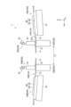
- FIG. 1 is a diagram for explaining an outline of an example of a fusion splicing device.
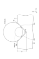
- FIG. 2 is a cross-sectional view for explaining a V-groove in an example fusion splicer.
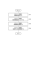
- FIG. 3 is a flow diagram showing the flow of an example fusion splicing method.
- An object of the present disclosure is to provide an optical fiber fusion splicing method and a fusion splicing device capable of shortening the length of the exposed glass fiber while suppressing the manufacturing cost of the device.
- a fusion splicing method is a method of fusion splicing an optical fiber strand in which the outer periphery of a glass fiber is coated with a coating portion to another optical fiber. This method comprises the steps of: exposing the glass fiber in the tip region by removing the coating of the tip region of the optical fiber strand; A step of arranging the optical fiber strand in the first V-groove so that the end face of the fiber faces each other, and a step of pressing the optical fiber strand arranged in the first V-groove against the first V-groove by a clamp.
- the step of arranging the optical fiber strand in the first V-groove includes arranging the unremoved coating portion region of the optical fiber strand in the first V-groove and changing the distance between the end faces.
- the optical fiber strand is slid on the V groove of 1.
- a fusion splicing device is a device that fusion splices an optical fiber bare wire in which the outer periphery of a glass fiber is coated with a coating portion to another optical fiber.
- This device has a first V-groove in which an optical fiber bare wire is placed, a second V-groove in which a glass fiber or other optical fiber contained in another optical fiber is placed, and a A clamp that presses the placed optical fiber strand to the bottom of the groove, an end face of the glass fiber of the optical fiber strand pressed into the first V-groove by the clamp, and other light placed in the second V-groove.
- the optical fiber strand pressed against the first V-groove by the clamp is slidably movable relative to the first V-groove.
- the coated portion of the optical fiber strand in which the glass fiber in the tip region is exposed is arranged in the first V-groove, and the optical fiber extends over the first V-groove.
- the movement of the optical fiber in the axial direction is achieved by the sliding of the coated portion of the strand. Therefore, the length of the exposed glass fiber can be shortened compared to the case where the exposed glass fiber in the optical fiber strand is arranged in the V-groove and slid.
- the manufacturing cost of the apparatus can be suppressed.
- the depth of the first V-groove may be set to 0.09 mm or more and 0.30 mm or less.
- the inclined surface forming the first V-groove is a plane tangential to the outer peripheral surface of the optical fiber. The optical fiber is easily arranged on the first V-groove, and it is suppressed that the optical fiber is caught on the upper end of the first V-groove. Further, since the outer circumference of the optical fiber protrudes from the inclined surface forming the first V-groove, the optical fiber can be reliably pressed by the clamp.
- the distance between the first V-groove and the second V-groove in which the glass fiber included in the other optical fiber or the other optical fiber is arranged may be set to 8 mm or more. With this configuration, damage to the coating due to arc discharge is suppressed.
- the force of the clamp pressing the optical fiber may be 14 gf or less. With this configuration, the friction generated between the optical fiber strand and the first V-groove can be reduced.
- FIG. 1 is a diagram for explaining an overview of a fusion splicing device 1 according to one aspect of the present disclosure.
- the fusion splicing device 1 includes a base 20, a clamp 30, and a stage 40.
- a fusion splicing device 1 is a device for fusion splicing a pair of optical fiber wires 10A and 10B.
- the optical fiber strands 10 ( 10 A, 10 B) are made up of a glass fiber (bare fiber) 11 and a coated portion 12 .
- the glass fiber 11 is made of silica glass or the like.
- the glass fiber 11 has a core and a clad.
- the coating portion 12 is a portion that coats the outer periphery of the glass fiber 11 .
- the covering portion 12 may be composed of a single layer, or may be composed of a plurality of layers.
- the material for forming the covering portion 12 includes ultraviolet curable resin, non-halogen resin, polyester elastomer resin, and the like.
- the base 20 has a V-groove 22 for arranging the optical fiber strand 10 .
- An exemplary fusion splicer 1 has a pair of bases 20A and 20B.
- the pair of optical fiber strands 10A and 10B are positioned by V grooves 22 respectively provided in the pair of bases 20A and 20B.
- An example base 20 has a top surface 21 .
- a V-groove 22 is formed in the upper end surface 21 .
- the upper end surface 21 of the illustrated example is formed flat along the XY plane.
- the V-groove 22 is linearly formed along the direction in which the pair of bases 20A and 20B face each other.
- the illustrated V-groove 22 is formed along the Y direction.
- the coating portion 12 is removed from the tip region of the optical fiber wire 10, and the glass fiber 11 is exposed.
- the V-groove 22 of the base 20 is provided with a region of the coated portion 12 of the optical fiber strand 10 that has not been removed. That is, on the V-groove 22, the covering portion 12 constituting the optical fiber strand 10 is arranged over the entire area in the Y direction. In this case, the glass fiber 11 exposed from the coating portion 12 in the tip region of the optical fiber strand 10 does not come into contact with the V-groove 22 .
- a pair of optical fiber strands 10A and 10B are arranged on the pair of V-grooves 22 so that the exposed glass fibers 11 in the tip regions face each other.
- an exemplary V-groove 22 is formed to have a V-shaped cross section by a pair of inclined surfaces 22a.
- the angle of the V-groove 22, that is, the angle ⁇ between the pair of inclined surfaces 22a may be, for example, about 60 degrees to 120 degrees, but is not particularly limited.
- the groove bottom, which is the connecting portion between the pair of inclined surfaces 22a, may have a curved shape, for example.
- the depth D from the upper end of the V-groove 22 to the groove bottom where the inclined surfaces 22a are connected to each other is determined by the angle ⁇ (degrees) of the opening between the inclined surfaces 22a and the coating portion 12 of the arranged optical fiber 10. It may be set according to the size. In one example, when the radius of the outer periphery of the covering portion 12 is R, the upper limit D1 of the depth of the V-groove 22 is may be specified in
- the lower limit D2 of the depth is may be specified in
- the depth D of the V-groove 22 is determined according to the above two equations, that is, if D2 ⁇ D ⁇ D1, the optical fiber 10 placed in the V-groove 22 is is in contact with the outer peripheral surface of the covering portion 12 so that the inclined surface 22a constituting the . It's sticking out.
- the inclined surface 22a of the V-groove 22 is in contact with the covering portion 12 of the optical fiber 10 so as to be a tangential plane, the covering portion 12 is not in contact with the upper corner portion 22b of the V-groove 22 .
- the depth of the V-groove 22 is approximately 0.09 mm or more in order to correspond to the optical fiber R125 having the radius R of the coating portion 12 of 0.125 mm. It is set to 0.30 mm or less. Further, when the angle of the V-groove 22 is 90 degrees, the depth of the V-groove 22 is approximately 0.045 mm or more in order to correspond to the optical fiber strand R65 in which the radius R of the coating portion 12 is 0.065 mm. It is set to 0.150 mm or less. In the example shown in FIG. 2, the angle of the V-groove 22 is 90 degrees and the depth D of the V-groove 22 is approximately 0.12 mm.
- the depth of the V groove 22 is the lower limit of the depth corresponding to the optical fiber wire R125 having the large radius R of the coating portion 12 and the depth corresponding to the optical fiber wire R65 having the small radius R of the coating portion 12. set between the upper limit and In this case, even if either the optical fiber R125 or the optical fiber R65 is arranged in the V-groove 22, the inclined surface 22a forming the V-groove 22 should be a plane tangential to the outer peripheral surface of the coating portion 12. , and the peripheral surface of the coating portion 12 opposite to the peripheral surface facing the groove bottom of the V-groove 22 protrudes from the V-groove 22 .
- the distance L1 (see FIG. 1) between the V-grooves 22 in which the pair of optical fiber wires 10A and 10B are arranged is the length of the coated portion of the optical fiber wire 10 when arc discharge fusion splicing is performed. 12 are set to be unaffected. As described above, the region of the coated portion 12 of the optical fiber strand 10 is arranged in the V-groove 22 . Therefore, the distance from the tip of the exposed glass fiber 11 to the tip of the coated portion 12 in the bare optical fiber 10 (that is, the length of the exposed glass fiber 11) is half the distance between the pair of V-grooves 22.
- the distance L1 between the pair of V-grooves 22 is too short, it is conceivable that the covering portion 12 will melt under the influence of arc discharge.
- the distance L1 between the V-grooves 22 in which the pair of optical fiber strands 10A and 10B are arranged may be set to approximately 8 mm or more.
- Each of the example bases 20 (20A, 20B) is configured to be movable in a direction intersecting the axial direction (Y direction) of the optical fiber strand 10 . That is, each of the bases 20 can adjust the position of the V-groove 22 in the direction crossing the axial direction of the optical fiber strand 10 .
- each base 20A, 20B may be movable in directions crossing each other.
- base 20A may be movable in the X direction and base 20B may be movable in the Z direction. That is, the base 20A may include a drive system for adjusting the position in the X direction, and the base 20B may include a drive system for adjusting the position in the Z direction.
- both the bases 20A and 20B may include drive systems for adjusting their positions in the X and Z directions, respectively.
- Each of the stages 40 (40A, 40B) is movable in the Y direction, and may further include a drive system for adjusting the position in each of the X and Z directions.
- a driving device for moving the holder (stage) to which the optical fiber is fixed, the V-groove, and the clamp as a unit in the Y direction may be omitted.
- a pair of clamps 30 press the optical fiber strands 10 arranged in the pair of V-grooves 22 toward the groove bottom side.
- An example clamp 30 includes a clamp body 31 and a biasing member 33 .
- the clamp body 31 contacts the coated portion 12 of the optical fiber wire 10 and presses the optical fiber wire 10 toward the V-groove 22 .
- the clamp body 31 is arranged above the V-groove 22 .
- the bottom surface 31 a of the clamp body 31 presses the optical fiber strand 10 .
- the bottom surface 31a of the clamp body 31 is configured by, for example, a downwardly convex curved surface.
- the bottom surface 31a in the illustrated example is formed in an arc shape when viewed from the X direction.
- the biasing member 33 is a member that biases the clamp body 31 toward the V groove 22 .
- the biasing member 33 may be an elastic body such as a spring.
- An example biasing member 33 is connected to the upper portion of the clamp body 31 .
- the biasing member 33 presses the clamp body 31 downward.
- the biasing member 33 presses the optical fiber 10 placed in the V-groove 22 so that the optical fiber 10 placed in the V-groove 22 can move in the axial direction while being pressed by the clamp body 31 .
- It may be designed so that the force for gripping (hereinafter referred to as gripping force) is between 2 gf and 14 gf.
- the gripping force in this case may be considered as the force of an elastic body such as a spring that presses the clamp body.
- the stages 40 (40A, 40B) hold the respective optical fiber strands 10 at positions closer to the proximal side than the positions pressed by the clamps 30.
- An example stage 40 includes a holder 45 and a movable stage 41 that holds the holder 45 .
- the holder 45 includes a lower member 42 and an upper member 43 , and holds the coated portion of the optical fiber strand 10 by being sandwiched between the lower member 42 and the upper member 43 .
- a movable stage 41 (driving system) holds a holder 45 . Further, the movable stage 41 moves the holder 45 along the axial direction of the optical fiber 10 (the Y direction in the illustrated example).
- the optical fiber strand 10 is moved relative to the clamp 30 and the V-groove 22 so as to slide on the V-groove 22 as the holder 45 moves.
- the distance between the end faces of the glass fibers 11 in the tip regions of the optical fiber 10 pressed against the V-grooves 22 by the pair of clamps 30A and 30B can be changed.
- FIG. 3 is a flow diagram showing an example of a fusion splicing method using the fusion splicing device 1.
- FIG. 3 is a flow diagram showing an example of a fusion splicing method using the fusion splicing device 1.
- the covering portion 12 in the tip region of each optical fiber strand 10 is removed (step S1).
- the glass fiber 11 is exposed in the tip region of the optical fiber strand 10 .
- the length of the exposed glass fiber 11 is not particularly limited, it may be, for example, about 3 mm.
- each of the pair of optical fiber strands 10A and 10B is held by a holder 45 on a movable stage 41.
- Each optical fiber strand 10 is arranged in the V-groove 22 so that the end faces of the glass fiber 11 in the exposed tip region face each other.
- the optical fiber wires 10 placed in the V-groove 22 are pressed against the V-groove 22 by the clamps 30 respectively.
- a region of the coated portion 12 that is not removed from the optical fiber strand 10 is arranged in the V-groove 22 .
- the optical fiber element is arranged so that the distance between the pair of glass fibers 11 is 2 mm or less.
- Line 10 will be set.
- the force with which the clamp 30 presses the optical fiber strand 10 may be 14 gf or less.
- step S3 the positions of the end surfaces of the glass fibers 11 in the tip region are adjusted so that the positions of the cores of the optical fiber strands 10 pressed against the V-grooves 22 by the clamps 30 are aligned in the X and Z directions.
- step S3 the positions of the end surfaces of the pair of glass fibers 11 in the X-axis direction and the Z-axis direction are controlled by driving the base 20 . Further, by driving the stage 40 to slide the optical fiber 10 on the V-groove 22, the position of the optical fiber 10 in the Y-axis direction is controlled to provide a predetermined end surface interval.
- step S4 the end faces of the glass fibers 11 are fusion-spliced by, for example, arc discharge using electrodes (not shown).
- the fusion splicing method is a method of fusion splicing the optical fiber strand 10A in which the outer periphery of the glass fiber 11 is coated with the coating portion 12 to another optical fiber strand 10B.
- This method includes a step of exposing the glass fiber 11 in the tip region by removing the coating 12 in the tip region of each optical fiber strand 10, and exposing the exposed glass fiber 11 in the tip region of the optical fiber strand 10A.
- the step of placing the optical fiber wire 10A in the V-groove 22 includes placing the region of the unremoved coating portion 12 of the optical fiber wire 10A in the V-groove 22 and changing the distance between the end faces of the optical fiber wire 10A.
- the optical fiber strand 10A is slid over 22 .
- the fusion splicing device 1 is a device for fusion splicing an optical fiber bare wire in which the outer periphery of a glass fiber 11 is coated with a coating portion 12 to another optical fiber.
- This device has a V-groove 22 (first V-groove) of a base 20A in which the optical fiber strand 10A is arranged, and a base in which the glass fiber 11 included in the optical fiber strand 10B or the optical fiber strand 10B is arranged.
- the base 20 includes the end face of the glass fiber 11 of the optical fiber strand 10A pressed into the V groove 22 of the base 20A by the clamp 30A, and the glass fiber 11 contained in the optical fiber strand 10B arranged in the V groove 22 of the base 20B. At least one of the optical fiber strand 10A and the optical fiber strand 10B is moved so as to change the distance from the end face of the base 20B or the end face of the glass fiber 11 placed in the V-groove 22 of the base 20B.
- the optical fiber strand 10A pressed against the V-groove 22 of the base 20A by the clamp 30A is slidably movable relative to the V-groove 22 of the base 20A.
- the end faces of a pair of glass fibers are butted against each other by sliding the glass fibers on the V-groove.
- the glass fiber slide only in the Y direction.
- the coating contacts the V-groove the movement of the glass fiber is impeded and the glass fiber can move in the X and Z directions as well. Therefore, the length of the exposed glass fiber can be set long enough to be equal to or greater than the sum of the length of the V-groove and the distance traveled by the glass fiber sliding over the V-groove.
- the region of the coated portion 12 in the optical fiber strand 10 where the glass fiber 11 in the tip region is exposed is arranged in the V groove 22.
- the axial movement is performed by sliding the optical fiber strand 10 . Therefore, the exposed length of the glass fiber 11 (that is, the length of the coating portion 12 to be removed) can be shortened compared to the case where the glass fiber 11 is placed in the V-groove 22 and slid. Furthermore, since it is not necessary to move the V-groove 22 and the clamp 30 together with the optical fiber 10, there is no need for a drive system for integrally moving the V-groove and the clamp together with the optical fiber 10. You can keep costs down.
- the depth of the V-groove 22 may be set to 0.09 mm or more and 0.30 mm or less.
- the inclined surface 22a forming the V-groove 22 is arranged to be a tangent plane to the outer peripheral surface of the optical fiber wire 10. Since they are in contact with each other, the optical fiber strand 10 is prevented from being caught on the upper end of the inclined surface 22a. Further, since the outer periphery of the optical fiber 10 protrudes from the V-groove 22, the optical fiber 10 can be reliably pressed by the clamp 30.
- the distance between the V-grooves 22 in which the pair of optical fiber wires 10A and 10B are arranged may be set to 8 mm or more. In this configuration, when the end faces of the pair of optical fiber wires 10A and 10B are butted against each other, the distance between the covering portions 12 can be properly maintained, so that the covering portions 12 are prevented from being damaged by arc discharge. is suppressed.
- the clamp 30 may press the optical fiber 10 with a force of 2 gf or more and 14 gf or less. With this configuration, the frictional force generated between the optical fiber strand 10 and the V-groove 22 can be reduced. 10 can be slid properly.
- the V-grooves may be formed in a base whose relative positions are fixed. That is, the fusion splicer may be a device that performs alignment by a so-called fixed V-groove method.
Landscapes
- Physics & Mathematics (AREA)
- Engineering & Computer Science (AREA)
- Plasma & Fusion (AREA)
- General Physics & Mathematics (AREA)
- Optics & Photonics (AREA)
- Mechanical Coupling Of Light Guides (AREA)
Abstract
Priority Applications (2)
| Application Number | Priority Date | Filing Date | Title |
|---|---|---|---|
| CN202280069915.0A CN118119869A (zh) | 2021-11-11 | 2022-11-09 | 光纤的熔接方法和光纤的熔接装置 |
| JP2023559874A JPWO2023085332A1 (fr) | 2021-11-11 | 2022-11-09 |
Applications Claiming Priority (2)
| Application Number | Priority Date | Filing Date | Title |
|---|---|---|---|
| JP2021-183914 | 2021-11-11 | ||
| JP2021183914 | 2021-11-11 |
Publications (1)
| Publication Number | Publication Date |
|---|---|
| WO2023085332A1 true WO2023085332A1 (fr) | 2023-05-19 |
Family
ID=86335755
Family Applications (1)
| Application Number | Title | Priority Date | Filing Date |
|---|---|---|---|
| PCT/JP2022/041759 Ceased WO2023085332A1 (fr) | 2021-11-11 | 2022-11-09 | Procédé d'épissage par fusion pour fibres optiques et dispositif d'épissage par fusion pour fibres optiques |
Country Status (3)
| Country | Link |
|---|---|
| JP (1) | JPWO2023085332A1 (fr) |
| CN (1) | CN118119869A (fr) |
| WO (1) | WO2023085332A1 (fr) |
Citations (2)
| Publication number | Priority date | Publication date | Assignee | Title |
|---|---|---|---|---|
| JPH05188233A (ja) * | 1992-01-13 | 1993-07-30 | Furukawa Electric Co Ltd:The | 光ファイバ接続治具 |
| JP2002286963A (ja) * | 2001-03-23 | 2002-10-03 | Sumitomo Electric Ind Ltd | 光ファイバの融着接続方法 |
-
2022
- 2022-11-09 CN CN202280069915.0A patent/CN118119869A/zh active Pending
- 2022-11-09 WO PCT/JP2022/041759 patent/WO2023085332A1/fr not_active Ceased
- 2022-11-09 JP JP2023559874A patent/JPWO2023085332A1/ja active Pending
Patent Citations (2)
| Publication number | Priority date | Publication date | Assignee | Title |
|---|---|---|---|---|
| JPH05188233A (ja) * | 1992-01-13 | 1993-07-30 | Furukawa Electric Co Ltd:The | 光ファイバ接続治具 |
| JP2002286963A (ja) * | 2001-03-23 | 2002-10-03 | Sumitomo Electric Ind Ltd | 光ファイバの融着接続方法 |
Also Published As
| Publication number | Publication date |
|---|---|
| JPWO2023085332A1 (fr) | 2023-05-19 |
| CN118119869A (zh) | 2024-05-31 |
Similar Documents
| Publication | Publication Date | Title |
|---|---|---|
| EP1302790A1 (fr) | Porte-conducteur de fibre optique, dispositif de connexion par fusion, dispositif de decoupe et procede de connexion de fibre optique | |
| CN100406941C (zh) | 光纤连接器和连接方法 | |
| JP2006221031A (ja) | 光学接続構造 | |
| CN101868744B (zh) | 光纤连接部件及其安装方法 | |
| JP7347762B2 (ja) | 光ファイバの融着接続方法 | |
| US8915100B2 (en) | Optical fiber end processing method and optical fiber end processing apparatus | |
| JP5416721B2 (ja) | 光ファイバ端部加工方法および光ファイバ端部加工装置 | |
| JPH04145403A (ja) | 多芯リボンテープ光ファイバ用分岐合流器およびその製造方法 | |
| JP5113344B2 (ja) | 光ファイバホルダ及びその使用方法 | |
| CN100549742C (zh) | 光互联器件 | |
| CN114041075B (zh) | 光纤排列方法、光纤熔接方法、带连接器光纤带的制造方法以及间歇连结型的光纤带 | |
| WO2023085332A1 (fr) | Procédé d'épissage par fusion pour fibres optiques et dispositif d'épissage par fusion pour fibres optiques | |
| CN1867850A (zh) | 用于制造带缆的装置及方法 | |
| CN107615122B (zh) | 光纤保持构件以及熔接机 | |
| JPH11305151A (ja) | 光スイッチの結合部及びその製造方法 | |
| JP4096493B2 (ja) | 端末ロッドレンズ付き光ファイバ及びその製造方法 | |
| WO2011061805A1 (fr) | Mécanisme de serrage de fibre | |
| US12554068B2 (en) | Optical fiber holder and method for connecting coated optical fibers | |
| JP2005148580A (ja) | 光学接続構造および光学接続方法 | |
| JP2004045935A (ja) | 光ファイバ接続用部品、光ファイバ接続構造および光ファイバ接続方法 | |
| JP2003156657A (ja) | 光ファイバアレイの製造方法 | |
| JP2025014092A (ja) | 融着接続機 | |
| JPH0827413B2 (ja) | 多心光ファイバの一括融着接続方法 | |
| KR20250086781A (ko) | 광섬유 절단 디바이스 및 광섬유 절단 방법 | |
| JPH06222241A (ja) | 光ファイバカプラ製造装置及び製造方法 |
Legal Events
| Date | Code | Title | Description |
|---|---|---|---|
| 121 | Ep: the epo has been informed by wipo that ep was designated in this application |
Ref document number: 22892830 Country of ref document: EP Kind code of ref document: A1 |
|
| ENP | Entry into the national phase |
Ref document number: 2023559874 Country of ref document: JP Kind code of ref document: A |
|
| WWE | Wipo information: entry into national phase |
Ref document number: 202280069915.0 Country of ref document: CN |
|
| 122 | Ep: pct application non-entry in european phase |
Ref document number: 22892830 Country of ref document: EP Kind code of ref document: A1 |