WO2023112800A1 - 液体燃料合成システム及び液体燃料合成方法 - Google Patents
液体燃料合成システム及び液体燃料合成方法 Download PDFInfo
- Publication number
- WO2023112800A1 WO2023112800A1 PCT/JP2022/045151 JP2022045151W WO2023112800A1 WO 2023112800 A1 WO2023112800 A1 WO 2023112800A1 JP 2022045151 W JP2022045151 W JP 2022045151W WO 2023112800 A1 WO2023112800 A1 WO 2023112800A1
- Authority
- WO
- WIPO (PCT)
- Prior art keywords
- liquid fuel
- gas
- raw material
- sweep gas
- hydrogen
- Prior art date
- Legal status (The legal status is an assumption and is not a legal conclusion. Google has not performed a legal analysis and makes no representation as to the accuracy of the status listed.)
- Ceased
Links
Images



Classifications
-
- B—PERFORMING OPERATIONS; TRANSPORTING
- B01—PHYSICAL OR CHEMICAL PROCESSES OR APPARATUS IN GENERAL
- B01J—CHEMICAL OR PHYSICAL PROCESSES, e.g. CATALYSIS OR COLLOID CHEMISTRY; THEIR RELEVANT APPARATUS
- B01J8/00—Chemical or physical processes in general, conducted in the presence of fluids and solid particles; Apparatus for such processes
- B01J8/008—Details of the reactor or of the particulate material; Processes to increase or to retard the rate of reaction
- B01J8/009—Membranes, e.g. feeding or removing reactants or products to or from the catalyst bed through a membrane
-
- B—PERFORMING OPERATIONS; TRANSPORTING
- B01—PHYSICAL OR CHEMICAL PROCESSES OR APPARATUS IN GENERAL
- B01D—SEPARATION
- B01D53/00—Separation of gases or vapours; Recovering vapours of volatile solvents from gases; Chemical or biological purification of waste gases, e.g. engine exhaust gases, smoke, fumes, flue gases, aerosols
- B01D53/22—Separation of gases or vapours; Recovering vapours of volatile solvents from gases; Chemical or biological purification of waste gases, e.g. engine exhaust gases, smoke, fumes, flue gases, aerosols by diffusion
-
- B—PERFORMING OPERATIONS; TRANSPORTING
- B01—PHYSICAL OR CHEMICAL PROCESSES OR APPARATUS IN GENERAL
- B01D—SEPARATION
- B01D53/00—Separation of gases or vapours; Recovering vapours of volatile solvents from gases; Chemical or biological purification of waste gases, e.g. engine exhaust gases, smoke, fumes, flue gases, aerosols
- B01D53/22—Separation of gases or vapours; Recovering vapours of volatile solvents from gases; Chemical or biological purification of waste gases, e.g. engine exhaust gases, smoke, fumes, flue gases, aerosols by diffusion
- B01D53/229—Integrated processes (Diffusion and at least one other process, e.g. adsorption, absorption)
-
- B—PERFORMING OPERATIONS; TRANSPORTING
- B01—PHYSICAL OR CHEMICAL PROCESSES OR APPARATUS IN GENERAL
- B01D—SEPARATION
- B01D53/00—Separation of gases or vapours; Recovering vapours of volatile solvents from gases; Chemical or biological purification of waste gases, e.g. engine exhaust gases, smoke, fumes, flue gases, aerosols
- B01D53/26—Drying gases or vapours
- B01D53/265—Drying gases or vapours by refrigeration (condensation)
-
- C—CHEMISTRY; METALLURGY
- C07—ORGANIC CHEMISTRY
- C07C—ACYCLIC OR CARBOCYCLIC COMPOUNDS
- C07C29/00—Preparation of compounds having hydroxy or O-metal groups bound to a carbon atom not belonging to a six-membered aromatic ring
- C07C29/15—Preparation of compounds having hydroxy or O-metal groups bound to a carbon atom not belonging to a six-membered aromatic ring by reduction of oxides of carbon exclusively
- C07C29/151—Preparation of compounds having hydroxy or O-metal groups bound to a carbon atom not belonging to a six-membered aromatic ring by reduction of oxides of carbon exclusively with hydrogen or hydrogen-containing gases
- C07C29/152—Preparation of compounds having hydroxy or O-metal groups bound to a carbon atom not belonging to a six-membered aromatic ring by reduction of oxides of carbon exclusively with hydrogen or hydrogen-containing gases characterised by the reactor used
-
- C—CHEMISTRY; METALLURGY
- C10—PETROLEUM, GAS OR COKE INDUSTRIES; TECHNICAL GASES CONTAINING CARBON MONOXIDE; FUELS; LUBRICANTS; PEAT
- C10G—CRACKING HYDROCARBON OILS; PRODUCTION OF LIQUID HYDROCARBON MIXTURES, e.g. BY DESTRUCTIVE HYDROGENATION, OLIGOMERISATION, POLYMERISATION; RECOVERY OF HYDROCARBON OILS FROM OIL-SHALE, OIL-SAND, OR GASES; REFINING MIXTURES MAINLY CONSISTING OF HYDROCARBONS; REFORMING OF NAPHTHA; MINERAL WAXES
- C10G2/00—Production of liquid hydrocarbon mixtures of undefined composition from oxides of carbon
- C10G2/50—Production of liquid hydrocarbon mixtures of undefined composition from oxides of carbon from carbon dioxide with hydrogen
-
- B—PERFORMING OPERATIONS; TRANSPORTING
- B01—PHYSICAL OR CHEMICAL PROCESSES OR APPARATUS IN GENERAL
- B01D—SEPARATION
- B01D2257/00—Components to be removed
- B01D2257/80—Water
-
- B—PERFORMING OPERATIONS; TRANSPORTING
- B01—PHYSICAL OR CHEMICAL PROCESSES OR APPARATUS IN GENERAL
- B01J—CHEMICAL OR PHYSICAL PROCESSES, e.g. CATALYSIS OR COLLOID CHEMISTRY; THEIR RELEVANT APPARATUS
- B01J19/00—Chemical, physical or physico-chemical processes in general; Their relevant apparatus
- B01J19/24—Stationary reactors without moving elements inside
- B01J19/2475—Membrane reactors
Definitions
- the present invention relates to a liquid fuel synthesizing system and a liquid fuel synthesizing method.
- Patent Document 1 discloses a liquid fuel synthesizing system that includes a membrane reactor, a source gas supply section, and a sweep gas supply section.
- the membrane reactor is equipped with a catalyst that advances the conversion reaction of a raw material gas containing hydrogen and carbon dioxide into methanol, and a separation membrane that allows water vapor, which is a by-product of the conversion reaction, to pass therethrough.
- the raw material gas supply unit supplies the raw material gas to the non-permeation side of the separation membrane.
- the sweep gas supply unit supplies a sweep gas to the permeation side of the separation membrane.
- the water vapor that permeates the separation membrane is discharged from the membrane reactor together with the sweep gas.
- the present invention has been made in view of the above situation, and aims to provide a liquid fuel synthesizing system and a liquid fuel synthesizing method capable of improving the utilization rate of raw material gas.
- a liquid fuel synthesis system includes a liquid fuel synthesis section and a sweep gas supply section.
- the liquid fuel synthesizing section permeates the product of the conversion reaction from the raw material gas containing at least hydrogen and carbon dioxide to the liquid fuel.
- the sweep gas supply unit supplies the liquid fuel synthesizing unit with a sweep gas for sweeping the product that has permeated the separation membrane.
- the sweep gas contains hydrogen or carbon dioxide as a main component.
- the liquid fuel synthesis system according to the second aspect of the present invention relates to the first aspect, and the sweep gas contains hydrogen as a main component.
- the liquid fuel synthesizing system according to the third aspect of the present invention relates to the second aspect, and the sweep gas contains carbon dioxide as an auxiliary component.
- a liquid fuel synthesizing system is a liquid fuel synthesizing system according to any one of the first to third aspects, which is discharged from the liquid fuel synthesizing section and removes moisture from the exhaust gas containing the sweep gas and products. Equipped with a moisture removing section.
- a liquid fuel synthesizing system relates to the fourth aspect, wherein the water removing section includes a heat exchanger using a material gas containing at least hydrogen and carbon dioxide as a refrigerant.
- a liquid fuel synthesizing system relates to the fifth aspect, in which the pressure of the mixed gas of the raw material gas and the sweep gas that has passed through the moisture removing section is increased and supplied to the liquid fuel synthesizing section. It has a pressure section.
- the raw material gas containing at least hydrogen and carbon dioxide is supplied to the non-permeate side of the separation membrane while the conversion reaction from the raw material gas to the liquid fuel proceeds. and supplying a sweep gas to the permeate side of the separation membrane for sweeping the products produced by the conversion reaction and permeating the separation membrane.
- the sweep gas contains hydrogen or carbon dioxide as a main component.
- the liquid fuel synthesizing method according to the eighth aspect of the present invention relates to the seventh aspect, further comprising the step of removing moisture from the sweep gas and the exhaust gas containing the product.
- the method for synthesizing liquid fuel according to the ninth aspect of the present invention relates to the eighth aspect, and in the step of removing moisture from the exhaust gas, a material gas containing at least hydrogen and carbon dioxide is used as a refrigerant.
- the liquid fuel synthesizing method according to the tenth aspect of the present invention relates to the ninth aspect, further comprising the step of increasing the pressure of the mixed gas of the raw material gas and the sweep gas after being used as a refrigerant.
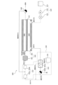
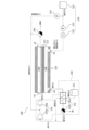
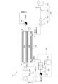
- Schematic diagram showing the configuration of a liquid fuel synthesizing system according to an embodiment Schematic diagram showing the configuration of a liquid fuel synthesizing system according to Modification 2 Schematic diagram showing the configuration of a liquid fuel synthesizing system according to modification 5
- Schematic diagram showing the configuration of a liquid fuel synthesizing system according to modification 5 Schematic diagram showing the configuration of a liquid fuel synthesizing system according to modification 5
- Schematic diagram showing the configuration of a liquid fuel synthesizing system according to modification 5 Schematic diagram showing the configuration of a liquid fuel synthesizing system according to modification 5
- FIG. 1 is a schematic diagram showing the configuration of a liquid fuel synthesizing system 100. As shown in FIG. The liquid fuel synthesis system 100 includes a liquid fuel synthesis section 110 , a sweep gas supply section 120 , a source gas supply section 130 and a first drain trap 140 .
- the liquid fuel synthesizing unit 110 is a so-called membrane reactor for converting raw material gas into liquid fuel.
- the shape of the liquid fuel synthesizing section 110 is not particularly limited, but may be, for example, a monolithic shape, a flat plate shape, a tubular shape, a cylindrical shape, a columnar shape, a polygonal columnar shape, or the like.
- a monolithic shape means a shape having a plurality of cells penetrating in the longitudinal direction, and is a concept including a honeycomb shape.
- the raw material gas is supplied from the raw material gas supply unit 130 to the liquid fuel synthesizing unit 110 .
- the source gas contains at least hydrogen and carbon dioxide.
- the source gas may contain carbon monoxide.
- the source gas may be a so-called synthesis gas (Syngas).
- the liquid fuel is a fuel that is liquid at room temperature and pressure, or a fuel that can be liquefied at room temperature and pressure. Examples of fuels in a liquid state at normal temperature and pressure include methanol, ethanol, liquid fuels represented by C n H 2 (m-2n) (m is an integer less than 90, n is an integer less than 30), and these mixtures. Fuels that can be liquefied at room temperature and under pressure include, for example, propane, butane, and mixtures thereof.
- reaction formula (1) for synthesizing methanol by catalytically hydrogenating a raw material gas containing carbon dioxide and hydrogen in the presence of a catalyst is as follows.
- the above reaction is an equilibrium reaction, and in order to increase both the conversion rate and the reaction rate, it is preferable to carry out the reaction at high temperature and high pressure (eg, 180°C or higher, 2 MPa or higher).
- the liquid fuel is in a gaseous state when it is synthesized, and is maintained in a gaseous state at least until it flows out from the liquid fuel synthesizing section 110 . It is preferable that the liquid fuel synthesizing unit 110 have heat resistance and pressure resistance suitable for desired synthesizing conditions of the liquid fuel.
- the liquid fuel synthesizing section 110 has a catalyst layer 111, a separation membrane 112, a non-permeate side space 110A, and a permeate side space 110B.
- the catalyst layer 111 is arranged in the non-permeation side space 110A. In the catalyst layer 111, the conversion reaction from the source gas to the liquid fuel proceeds.
- the catalyst layer 111 is a porous body composed of a porous material and a catalyst.
- the average pore diameter of the catalyst layer 111 can be 5 ⁇ m or more and 25 ⁇ m or less.
- the average pore diameter of the catalyst layer 111 can be measured by mercury porosimetry.
- the porosity of the catalyst layer 111 can be 25% or more and 50% or less.
- the average particle size of the porous material forming the catalyst layer 111 can be set to 1 ⁇ m or more and 100 ⁇ m or less. In the present embodiment, the average particle size is the arithmetic average of the maximum diameters of 30 particles (randomly selected) measured by cross-sectional microstructure observation using a SEM (Scanning Electron Microscope).
- a ceramic material As the porous material, a ceramic material, a metal material, a resin material, or the like can be used, and a ceramic material is particularly suitable.
- Alumina Al 2 O 3
- titania TiO 2
- mullite Al 2 O 3 SiO 2
- cerubene cordierite
- cordierite Mg 2 Al 4 Si 5 O 18
- Alumina is preferred in consideration of availability, clay stability and corrosion resistance.
- At least one of titania, mullite, sinterable alumina, silica, glass frit, clay mineral, and sinterable cordierite can be used as the inorganic binder for the ceramic material.
- the ceramic material does not have to contain an inorganic binder.
- the catalyst advances the conversion reaction from raw material gas to liquid fuel.
- a catalyst is disposed within the pores of the porous material.
- the catalyst may be supported on the inner surfaces of the pores.
- a carrier that supports the catalyst may adhere to the inner surfaces of the pores.
- a known catalyst suitable for the conversion reaction to the desired liquid fuel may be used as the catalyst.
- metal catalysts copper, palladium, etc.
- oxide catalysts zinc oxide, zirconia, gallium oxide, etc.
- composite catalysts of these copper-zinc oxide, copper-zinc oxide-alumina, copper -zinc oxide-chromium oxide-alumina, copper-cobalt-titania, and catalysts obtained by modifying these with palladium
- the separation membrane 112 allows water vapor, which is one of the products of the conversion reaction from the source gas to the liquid fuel, to permeate.
- the equilibrium shift effect can be used to shift the reaction equilibrium of the above formula (1) to the product side.
- the molecular diameter of water (0.26 nm) is close to the molecular diameter of hydrogen (0.296 nm). Therefore, in the present embodiment, it is assumed that not only water vapor, which is a product of the conversion reaction, but also part of the hydrogen contained in the raw material gas permeates through the separation membrane 112 .
- Separation membrane 112 preferably has a water vapor permeability coefficient of 100 nmol/(s ⁇ Pa ⁇ m 2 ) or more.
- the water vapor permeability coefficient can be determined by a known method (see Ind. Eng. Chem. Res., 40, 163-175 (2001)).
- the separation membrane 112 preferably has a separation factor of 100 or more.
- the higher the separation factor the easier it is for water vapor to permeate, and the less it is for components other than water vapor (hydrogen, carbon dioxide, liquid fuel, etc.) to permeate.
- the separation factor can be determined by a known method (see Fig. 1 of "Separation and Purification Technology 239 (2020) 116533").
- An inorganic membrane can be used as the separation membrane 112 .
- An inorganic film is preferable because it has heat resistance, pressure resistance, and water vapor resistance.
- inorganic membranes include zeolite membranes, silica membranes, alumina membranes, and composite membranes thereof.
- zeolite membranes silica membranes, alumina membranes, and composite membranes thereof.
- an LTA-type zeolite membrane in which the molar ratio (Si/Al) of silicon element (Si) and aluminum element (Al) is 1.0 or more and 3.0 or less is preferable because it has excellent water vapor permeability. be.
- separation membrane 112 may be supported by a porous substrate.
- the non-permeation-side space 110A is the space on the non-permeation side of the separation membrane 112 .
- the raw material gas is supplied from the raw material gas supply unit 130 to the non-permeation side space 110A.
- the raw material gas flows into the non-permeation side space 110A through the inlet a1.
- the liquid fuel synthesized in the catalyst layer 111 flows out from the non-permeate side space 110A through the outlet a2.
- the liquid fuel flowing out from the outlet a2 may contain unreacted residual raw material gas.
- the residual raw material gas mixed in the liquid fuel is separated from the liquid fuel in the first drain trap 140 .
- the separated residual raw material gas is returned to the raw material gas supply unit 130 (specifically, a second booster pump 133b described later).
- the residual source gas contains at least one of hydrogen and carbon dioxide.
- the permeation-side space 110B is the space on the permeation side of the separation membrane 112 . Water vapor and hydrogen that have passed through the separation membrane 112 flow into the permeation-side space 110B.
- a sweep gas is supplied from the sweep gas supply unit 120 to the permeation-side space 110B. The sweep gas flows into the permeation side space 110B through the inlet b1. The exhaust gas containing the sweep gas and water vapor flows out of the permeation side space 110B through the outlet b2.
- the sweep gas supply unit 120 is arranged on the upstream side of the permeation side space 110B.
- the sweep gas supply section 120 has a storage section 121 , a flow rate adjustment mechanism 122 and a heating section 123 .
- the storage unit 121 stores the sweep gas.
- the sweep gas contains hydrogen or carbon dioxide as a main component.
- the sweep gas containing hydrogen or carbon dioxide as a main component allows the hydrogen permeating the separation membrane 112 to be reused as part of the source gas without being separated from the sweep gas. As a result, it is possible to easily improve the utilization rate of the raw material gas. Containing hydrogen or carbon dioxide as a main component means that the content of hydrogen or carbon dioxide is the highest among the gases contained in the sweep gas.
- the sweep gas may contain only one of hydrogen and carbon dioxide, but may contain both hydrogen and carbon dioxide.
- the specific heat of the sweep gas can be increased compared to when the sweep gas contains only one of hydrogen and carbon dioxide. Heat removal efficiency can be improved.
- the sweep gas preferably contains hydrogen as its main component.
- the hydrogen content in the water sweep gas is not particularly limited, but can be, for example, 60 mol % or more and 100 mol % or less.
- the sweep gas preferably contains carbon dioxide as an auxiliary component.
- carbon dioxide as an auxiliary component.
- Containing carbon dioxide as a secondary component means that the content of carbon dioxide in the gases contained in the sweep gas is the second highest after hydrogen (ie, second highest).
- the content of carbon dioxide in the sweep gas is not particularly limited, but can be, for example, 5 mol % or more and 40 mol % or less.
- the flow rate adjustment mechanism 122 adjusts the flow rate of the sweep gas supplied from the reservoir 121 .
- a pump, a blower, or the like can be used as the flow rate adjustment mechanism 122 .
- the flow rate adjustment mechanism 122 can be omitted.
- the heating unit 123 heats the sweep gas to a desired temperature.
- the heating unit 123 is not particularly limited as long as it can heat the sweep gas.
- the heating unit 123 may heat using a regenerative heat exchanger that utilizes heat exchange with a heat exchanger 132a, which will be described later.
- the source gas supply unit 130 is arranged downstream of the non-permeation side space 110A.
- the raw material gas supply unit 130 has a raw material gas source 131 , a water removing unit 132 , and a pressure increasing unit 133 .
- the material gas source 131 stores material gas.
- the material gas contains at least hydrogen and carbon dioxide.
- the material gas may contain carbon monoxide.
- the source gas may be a so-called synthesis gas (Syngas).
- Syngas synthesis gas
- the moisture removal unit 132 removes moisture from the exhaust gas discharged from the liquid fuel synthesizing unit and containing the sweep gas and water vapor. This separates the sweep gas from the exhaust gas.
- the moisture remover 132 includes a heat exchanger 132a and a second drain trap 132b.
- the heat exchanger 132a has a first flow path c1 through which the raw material gas supplied from the raw material gas source 131 flows, and a second flow path c2 through which the exhaust gas discharged from the liquid fuel synthesizing section 110 flows.
- the heat exchanger 132a condenses water vapor in the exhaust gas into water by using the material gas as a refrigerant. As a result, heating of the raw material gas and cooling of the exhaust gas can be performed simultaneously, so that the thermal efficiency of the liquid fuel synthesizing system 100 can be improved.
- the second drain trap 132b is arranged downstream of the heat exchanger 132a.
- a second drain trap 132b separates the water condensed in the heat exchanger 132a from the sweep gas.
- the sweep gas separated by the second drain trap 132b is mixed with the material gas that has passed through the heat exchanger 132a on the downstream side of the second drain trap 132b. As a result, a mixed gas in which the sweep gas and the material gas are mixed is generated.
- the mixed gas is supplied to the pressure increasing section 133.
- the pressure increasing section 133 is arranged downstream of the second drain trap 132 b and upstream of the liquid fuel synthesizing section 110 .
- the pressure increasing unit 133 increases the pressure of the source gas and the sweep gas that have passed through the water removing unit 132 and supplies the increased pressure to the liquid fuel synthesizing unit 110 .
- the pressure booster 133 includes a first boost pump 133a and a second boost pump 133b.
- the first boosting pump 133a boosts the mixed gas to a predetermined first pressure.
- the mixed gas pressurized by the first booster pump 133 a is mixed with the residual raw material gas separated from the liquid fuel in the first drain trap 140 .
- a raw material gas in which the mixed gas and the residual raw material gas are mixed is generated.
- the second boosting pump 133b boosts the raw material gas to a predetermined second pressure.
- the second pressure is a pressure suitable for conversion reaction from raw material gas to liquid fuel, and is higher than the first pressure.
- the raw material gas pressurized by the second booster pump 133b is supplied to the non-permeation side space 110A of the liquid fuel synthesizing section 110. As shown in FIG.
- the liquid fuel synthesizing method includes a step of supplying a raw material gas to the non-permeate side of the separation membrane 112 and supplying a sweep gas containing hydrogen or carbon dioxide as a main component to the permeate side of the separation membrane 112 .
- a sweep gas containing hydrogen or carbon dioxide as a main component to the permeate side of the separation membrane 112 .
- the conversion reaction from the source gas to the liquid fuel proceeds.
- water vapor permeating through the separation membrane 112 is taken into the sweep gas.
- the liquid fuel synthesis method further comprises a step of removing moisture from the sweep gas and the exhaust gas containing water vapor.
- the material gas is used as a refrigerant in this step.
- the liquid fuel synthesizing method further includes a step of increasing the pressure of the mixed gas of the raw material gas and the sweep gas after being used as a refrigerant.
- the raw material gas is preferably generated by mixing the residual raw material gas separated from the liquid fuel with the mixed gas. This makes it possible to improve the utilization efficiency of the raw material gas.
- the catalyst layer 111 is arranged on the separation membrane 112, but it is not limited to this.
- the non-permeate side space 110A may be filled with a particulate catalyst.
- the particle size (diameter) of the particulate catalyst is not particularly limited, it can be, for example, 0.5 mm or more and 10 mm or less.
- the liquid fuel synthesizing system 100 is provided with the liquid fuel synthesizing unit 110, which is a membrane reactor, but is not limited to this.
- the liquid fuel synthesis system 100 may include a liquid fuel synthesis section 160 having a catalyst section 161 and a separation section 162, as shown in FIG.
- a raw material gas is supplied from the raw material gas supply unit 130 to the catalyst unit 161 .
- the catalyst described in the above embodiment is arranged in the catalyst portion 161 .
- the catalyst unit 161 converts the source gas into liquid fuel.
- the separation section 162 has a separation membrane 112, a non-permeate side space 160A and a permeate side space 160B.
- Liquid fuel, water vapor, and residual fuel gas flow into the non-permeation side space 160A. Water vapor permeates the separation membrane 112 . Also, part of the hydrogen contained in the residual fuel gas permeates the separation membrane 112 . The liquid fuel flows out from the non-permeate side space 160A without permeating the separation membrane 112 .
- the sweep gas contains hydrogen or carbon dioxide as a main component, so that the hydrogen that permeates the separation membrane 112 can be reused as part of the source gas without being separated from the sweep gas. As a result, it is possible to easily improve the utilization rate of the raw material gas.
- the material gas supplied from the material gas source 131 is used as the refrigerant for the heat exchanger 132a, but the present invention is not limited to this. Water or the like may be used as the refrigerant for the heat exchanger 132a. In this case, the material gas may be directly mixed with the sweep gas flowing out of the second drain trap 132b without passing through the heat exchanger 132a.
- part of the residual raw material gas may be mixed with the sweep gas flowing out from the reservoir 121 and supplied to the flow rate adjustment mechanism 122 .
- part of the residual raw material gas is used as part of the sweep gas.
- the mixed amount of the remaining raw material gas can be adjusted by the flow rate adjusting mechanism 124 .
- all of the remaining raw material gas may be mixed with the sweep gas flowing out from the storage section 121 and supplied to the flow rate adjustment mechanism 122 .
- the remaining raw material gas flows to the flow rate adjusting mechanism 122 side because the check valve 125 restricts the remaining raw material gas from flowing to the storing section 121 side.
- all of the remaining source gas is used as part of the sweep gas.
- the sweep gas supply unit 120 may not have the storage unit 121 and part of the residual raw material gas may be supplied to the flow rate adjustment mechanism 122 .
- part of the residual raw material gas is used as it is as the sweep gas.
- the supply amount of the sweep gas (residual raw material gas) can be adjusted by the flow rate adjustment mechanism 122 .
- the sweep gas supply unit 120 may not have the storage unit 121 and all of the remaining raw material gas may be supplied to the flow rate adjustment mechanism 122 . In this case, all of the remaining raw material gas is used as it is as the sweep gas.
- the separation membrane 112 is configured to permeate water vapor, which is one of the products of the conversion reaction from the raw material gas to the liquid fuel, but is not limited to this.
- the separation membrane 112 may permeate the liquid fuel itself produced by the conversion reaction from the source gas to the liquid fuel. Also in this case, the reaction equilibrium of the above formula (1) can be shifted to the product side.
- the separation membrane 112 is permeable to the liquid fuel, even when the liquid fuel is generated by a reaction that does not generate water vapor (for example, 2H 2 +CO ⁇ CH 3 OH), the reaction equilibrium is shifted to the product side. be able to.
- a reaction that does not generate water vapor for example, 2H 2 +CO ⁇ CH 3 OH
- liquid fuel synthesizing system 110 liquid fuel synthesizing section 111 catalyst layer 112 separation membrane 110A non-permeate side space 110B permeate side space 120 sweep gas supply section 130 source gas supply section
Landscapes
- Chemical & Material Sciences (AREA)
- Organic Chemistry (AREA)
- Chemical Kinetics & Catalysis (AREA)
- Oil, Petroleum & Natural Gas (AREA)
- Engineering & Computer Science (AREA)
- General Chemical & Material Sciences (AREA)
- Analytical Chemistry (AREA)
- Thermal Sciences (AREA)
- Physics & Mathematics (AREA)
- Separation Using Semi-Permeable Membranes (AREA)
- Hydrogen, Water And Hydrids (AREA)
- Carbon And Carbon Compounds (AREA)
- Liquid Carbonaceous Fuels (AREA)
- Production Of Liquid Hydrocarbon Mixture For Refining Petroleum (AREA)
- Organic Low-Molecular-Weight Compounds And Preparation Thereof (AREA)
Abstract
Description
図1は、液体燃料合成システム100の構成を示す模式図である。液体燃料合成システム100は、液体燃料合成部110と、掃引ガス供給部120と、原料ガス供給部130と、第1ドレントラップ140とを備える。
次に、液体燃料合成システム100を用いた液体燃料合成方法について説明する。
以上、本発明の一実施形態について説明したが、本発明は上記実施形態に限定されるものではなく、発明の要旨を逸脱しない範囲で種々の変更が可能である。
上記実施形態では、触媒層111が分離膜112上に配置されることとしたが、これに限られない。例えば、非透過側空間110Aに粒子状の触媒が充填されていてもよい。粒子状の触媒の粒子径(直径)は特に制限されないが、例えば0.5mm以上10mm以下とすることができる。
上記実施形態において、液体燃料合成システム100は、メンブレンリアクタである液体燃料合成部110を備えることとしたが、これに限られない。
図1及び図2では、分離膜112の側面視において、原料ガスと掃引ガスとが逆向き(すなわち、対向する向き)に流れることとしたが、互いに同じ向き(すなわち、平行な向き)に流れてもよい。
上記実施形態では、素材ガス源131から供給される素材ガスを熱交換器132aの冷媒として用いることとしたが、これに限られない。熱交換器132aの冷媒としては、水などを用いてもよい。この場合、素材ガスは、熱交換器132aを通過することなく、第2ドレントラップ132bから流出する掃引ガスに直接混合させてよい。
上記実施形態では、第1ドレントラップ140において液体燃料から分離された残原料ガスは、原料ガス供給部130に全て戻されることとしたが、これに限られない。
上記実施形態において、分離膜112は、原料ガスから液体燃料への転化反応の生成物の一つである水蒸気を透過させることとしたが、これに限られない。分離膜112は、原料ガスから液体燃料への転化反応によって生成される液体燃料自体を透過させてもよい。この場合においても、上記式(1)の反応平衡を生成物側にシフトさせることができる。
100 液体燃料合成システム
110 液体燃料合成部
111 触媒層
112 分離膜
110A 非透過側空間
110B 透過側空間
120 掃引ガス供給部
130 原料ガス供給部
Claims (10)
- 少なくとも水素及び二酸化炭素を含有する原料ガスから液体燃料への転化反応における生成物を透過させる分離膜を有する液体燃料合成部と、
前記分離膜を透過した前記生成物を掃引するための掃引ガスを前記液体燃料合成部に供給する掃引ガス供給部と、
を備え、
前記掃引ガスは、水素又は二酸化炭素を主成分として含有する、
液体燃料合成システム。 - 前記掃引ガスは、水素を主成分として含有する、
請求項1に記載の液体燃料合成システム。 - 前記掃引ガスは、二酸化炭素を副成分として含有する、
請求項2に記載の液体燃料合成システム。 - 前記液体燃料合成部から排出され、前記掃引ガス及び前記生成物を含有する排ガスから水分を除去する水分除去部を備える、
請求項1乃至3のいずれかに記載の液体燃料合成システム。 - 前記水分除去部は、少なくとも水素及び二酸化炭素を含有する素材ガスを冷媒として用いる熱交換器を含む、
請求項4に記載の液体燃料合成システム。 - 前記水分除去部を通過した前記素材ガスと前記掃引ガスとの混合ガスを増圧して前記液体燃料合成部に供給する増圧部を備える、
請求項5に記載の液体燃料合成システム。 - 少なくとも水素及び二酸化炭素を含有する原料ガスを分離膜の非透過側に供給することによって前記原料ガスから液体燃料への転化反応を進行させながら、前記転化反応によって生成されて前記分離膜を透過する生成物を掃引するための掃引ガスを前記分離膜の透過側に供給する工程を備え、
前記掃引ガスは、水素又は二酸化炭素を主成分として含有する、
液体燃料合成方法。 - 前記掃引ガス及び前記生成物を含有する排ガスから水分を除去する工程を更に備える、
請求項7に記載の液体燃料合成方法。 - 前記排ガスから水分を除去する工程では、少なくとも水素及び二酸化炭素を含有する素材ガスを冷媒として用いる、
請求項8に記載の液体燃料合成方法。 - 冷媒として用いられた後の前記素材ガスと前記掃引ガスとの混合ガスを増圧する工程を更に備える、
請求項9に記載の液体燃料合成方法。
Priority Applications (6)
| Application Number | Priority Date | Filing Date | Title |
|---|---|---|---|
| AU2022408465A AU2022408465B2 (en) | 2021-12-17 | 2022-12-07 | Liquid fuel synthesis system and liquid fuel synthesis method |
| JP2023535374A JP7850507B2 (ja) | 2021-12-17 | 2022-12-07 | 液体燃料合成システム及び液体燃料合成方法 |
| EP22907327.5A EP4296336A4 (en) | 2021-12-17 | 2022-12-07 | SYSTEM AND METHOD FOR THE SYNTHESIS OF LIQUID FUEL |
| CN202280026317.5A CN117157379A (zh) | 2021-12-17 | 2022-12-07 | 液体燃料合成系统以及液体燃料合成方法 |
| US18/363,014 US20230372887A1 (en) | 2021-12-17 | 2023-08-01 | Liquid fuel synthesis system and liquid fuel synthesis method |
| JP2024041321A JP2024069505A (ja) | 2021-12-17 | 2024-03-15 | 液体燃料合成システム及び液体燃料合成方法 |
Applications Claiming Priority (4)
| Application Number | Priority Date | Filing Date | Title |
|---|---|---|---|
| JP2021-204940 | 2021-12-17 | ||
| JP2021204940 | 2021-12-17 | ||
| JP2022074719 | 2022-04-28 | ||
| JP2022-074719 | 2022-04-28 |
Related Child Applications (1)
| Application Number | Title | Priority Date | Filing Date |
|---|---|---|---|
| US18/363,014 Continuation US20230372887A1 (en) | 2021-12-17 | 2023-08-01 | Liquid fuel synthesis system and liquid fuel synthesis method |
Publications (1)
| Publication Number | Publication Date |
|---|---|
| WO2023112800A1 true WO2023112800A1 (ja) | 2023-06-22 |
Family
ID=86774590
Family Applications (1)
| Application Number | Title | Priority Date | Filing Date |
|---|---|---|---|
| PCT/JP2022/045151 Ceased WO2023112800A1 (ja) | 2021-12-17 | 2022-12-07 | 液体燃料合成システム及び液体燃料合成方法 |
Country Status (5)
| Country | Link |
|---|---|
| US (1) | US20230372887A1 (ja) |
| EP (1) | EP4296336A4 (ja) |
| JP (2) | JP7850507B2 (ja) |
| AU (1) | AU2022408465B2 (ja) |
| WO (1) | WO2023112800A1 (ja) |
Cited By (2)
| Publication number | Priority date | Publication date | Assignee | Title |
|---|---|---|---|---|
| WO2024048637A1 (ja) * | 2022-09-02 | 2024-03-07 | 日本碍子株式会社 | 液体燃料製造システムおよび液体燃料の製造方法 |
| JPWO2024048636A1 (ja) * | 2022-09-02 | 2024-03-07 |
Families Citing this family (1)
| Publication number | Priority date | Publication date | Assignee | Title |
|---|---|---|---|---|
| WO2026014060A1 (ja) * | 2024-07-11 | 2026-01-15 | 日本碍子株式会社 | 燃料製造システム |
Citations (4)
| Publication number | Priority date | Publication date | Assignee | Title |
|---|---|---|---|---|
| JPH09511509A (ja) * | 1994-04-08 | 1997-11-18 | メサノール カサーレ ソシエテ アノニーム | メタノールの製造方法 |
| JP2018008940A (ja) | 2016-07-04 | 2018-01-18 | 公益財団法人地球環境産業技術研究機構 | メタノール製造方法およびメタノール製造装置 |
| JP2019156658A (ja) * | 2018-03-08 | 2019-09-19 | Jfeスチール株式会社 | 二酸化炭素の再利用方法 |
| JP7151832B1 (ja) * | 2021-06-11 | 2022-10-12 | Jfeスチール株式会社 | 膜反応器における未利用ガスの再利用方法 |
Family Cites Families (1)
| Publication number | Priority date | Publication date | Assignee | Title |
|---|---|---|---|---|
| EP1089956B1 (en) * | 1998-06-11 | 2003-11-05 | Sasol Technology (Proprietary) Limited | Production of hydrocarbons |
-
2022
- 2022-12-07 WO PCT/JP2022/045151 patent/WO2023112800A1/ja not_active Ceased
- 2022-12-07 JP JP2023535374A patent/JP7850507B2/ja active Active
- 2022-12-07 AU AU2022408465A patent/AU2022408465B2/en active Active
- 2022-12-07 EP EP22907327.5A patent/EP4296336A4/en active Pending
-
2023
- 2023-08-01 US US18/363,014 patent/US20230372887A1/en active Pending
-
2024
- 2024-03-15 JP JP2024041321A patent/JP2024069505A/ja active Pending
Patent Citations (4)
| Publication number | Priority date | Publication date | Assignee | Title |
|---|---|---|---|---|
| JPH09511509A (ja) * | 1994-04-08 | 1997-11-18 | メサノール カサーレ ソシエテ アノニーム | メタノールの製造方法 |
| JP2018008940A (ja) | 2016-07-04 | 2018-01-18 | 公益財団法人地球環境産業技術研究機構 | メタノール製造方法およびメタノール製造装置 |
| JP2019156658A (ja) * | 2018-03-08 | 2019-09-19 | Jfeスチール株式会社 | 二酸化炭素の再利用方法 |
| JP7151832B1 (ja) * | 2021-06-11 | 2022-10-12 | Jfeスチール株式会社 | 膜反応器における未利用ガスの再利用方法 |
Non-Patent Citations (2)
| Title |
|---|
| IND. ENG. CHEM. RES., vol. 40, 2001, pages 163 - 175 |
| See also references of EP4296336A4 |
Cited By (6)
| Publication number | Priority date | Publication date | Assignee | Title |
|---|---|---|---|---|
| WO2024048637A1 (ja) * | 2022-09-02 | 2024-03-07 | 日本碍子株式会社 | 液体燃料製造システムおよび液体燃料の製造方法 |
| JPWO2024048636A1 (ja) * | 2022-09-02 | 2024-03-07 | ||
| WO2024048636A1 (ja) * | 2022-09-02 | 2024-03-07 | 日本碍子株式会社 | 液体燃料製造システムおよび液体燃料の製造方法 |
| JPWO2024048637A1 (ja) * | 2022-09-02 | 2024-03-07 | ||
| JP7825057B2 (ja) | 2022-09-02 | 2026-03-05 | 日本碍子株式会社 | 液体燃料製造システムおよび液体燃料の製造方法 |
| JP7825058B2 (ja) | 2022-09-02 | 2026-03-05 | 日本碍子株式会社 | 液体燃料製造システムおよび液体燃料の製造方法 |
Also Published As
| Publication number | Publication date |
|---|---|
| EP4296336A4 (en) | 2024-10-16 |
| JP7850507B2 (ja) | 2026-04-23 |
| EP4296336A1 (en) | 2023-12-27 |
| JP2024069505A (ja) | 2024-05-21 |
| AU2022408465B2 (en) | 2025-06-19 |
| US20230372887A1 (en) | 2023-11-23 |
| JPWO2023112800A1 (ja) | 2023-06-22 |
| AU2022408465A9 (en) | 2024-09-19 |
| AU2022408465A1 (en) | 2023-08-24 |
Similar Documents
| Publication | Publication Date | Title |
|---|---|---|
| US20230372887A1 (en) | Liquid fuel synthesis system and liquid fuel synthesis method | |
| US20250197732A1 (en) | Liquid fuel production system and liquid fuel production method | |
| JP2024103728A (ja) | メンブレンリアクタ | |
| US20250197751A1 (en) | Liquid fuel production system and liquid fuel production method | |
| JP7823205B2 (ja) | 液体燃料製造システムおよび液体燃料の製造方法 | |
| CN117157379A (zh) | 液体燃料合成系统以及液体燃料合成方法 | |
| CN115943194B (zh) | 液体燃料合成系统 | |
| US20250197748A1 (en) | Method for producing liquid fuel and liquid fuel synthesis system | |
| US20250197749A1 (en) | Method for producing liquid fuel and liquid fuel synthesis system | |
| JP7637310B2 (ja) | リアクタモジュール |
Legal Events
| Date | Code | Title | Description |
|---|---|---|---|
| WWE | Wipo information: entry into national phase |
Ref document number: 2023535374 Country of ref document: JP |
|
| 121 | Ep: the epo has been informed by wipo that ep was designated in this application |
Ref document number: 22907327 Country of ref document: EP Kind code of ref document: A1 |
|
| ENP | Entry into the national phase |
Ref document number: 2022408465 Country of ref document: AU Date of ref document: 20221207 Kind code of ref document: A |
|
| WWE | Wipo information: entry into national phase |
Ref document number: 2022907327 Country of ref document: EP |
|
| ENP | Entry into the national phase |
Ref document number: 2022907327 Country of ref document: EP Effective date: 20230919 |
|
| NENP | Non-entry into the national phase |
Ref country code: DE |