WO2023120523A1 - 作業車 - Google Patents
作業車 Download PDFInfo
- Publication number
- WO2023120523A1 WO2023120523A1 PCT/JP2022/046884 JP2022046884W WO2023120523A1 WO 2023120523 A1 WO2023120523 A1 WO 2023120523A1 JP 2022046884 W JP2022046884 W JP 2022046884W WO 2023120523 A1 WO2023120523 A1 WO 2023120523A1
- Authority
- WO
- WIPO (PCT)
- Prior art keywords
- trunnion shaft
- gear
- shaft
- continuously variable
- variable transmission
- Prior art date
- Legal status (The legal status is an assumption and is not a legal conclusion. Google has not performed a legal analysis and makes no representation as to the accuracy of the status listed.)
- Ceased
Links
Images





Classifications
-
- B—PERFORMING OPERATIONS; TRANSPORTING
- B62—LAND VEHICLES FOR TRAVELLING OTHERWISE THAN ON RAILS
- B62D—MOTOR VEHICLES; TRAILERS
- B62D49/00—Tractors
- B62D49/06—Tractors adapted for multi-purpose use
-
- F—MECHANICAL ENGINEERING; LIGHTING; HEATING; WEAPONS; BLASTING
- F16—ENGINEERING ELEMENTS AND UNITS; GENERAL MEASURES FOR PRODUCING AND MAINTAINING EFFECTIVE FUNCTIONING OF MACHINES OR INSTALLATIONS; THERMAL INSULATION IN GENERAL
- F16H—GEARING
- F16H61/00—Control functions within control units of change-speed- or reversing-gearings for conveying rotary motion ; Control of exclusively fluid gearing, friction gearing, gearings with endless flexible members or other particular types of gearing
- F16H61/26—Generation or transmission of movements for final actuating mechanisms
- F16H61/28—Generation or transmission of movements for final actuating mechanisms with at least one movement of the final actuating mechanism being caused by a non-mechanical force, e.g. power-assisted
- F16H61/32—Electric motors , actuators or related electrical control means therefor
-
- F—MECHANICAL ENGINEERING; LIGHTING; HEATING; WEAPONS; BLASTING
- F16—ENGINEERING ELEMENTS AND UNITS; GENERAL MEASURES FOR PRODUCING AND MAINTAINING EFFECTIVE FUNCTIONING OF MACHINES OR INSTALLATIONS; THERMAL INSULATION IN GENERAL
- F16H—GEARING
- F16H61/00—Control functions within control units of change-speed- or reversing-gearings for conveying rotary motion ; Control of exclusively fluid gearing, friction gearing, gearings with endless flexible members or other particular types of gearing
- F16H61/38—Control of exclusively fluid gearing
- F16H61/40—Control of exclusively fluid gearing hydrostatic
- F16H61/42—Control of exclusively fluid gearing hydrostatic involving adjustment of a pump or motor with adjustable output or capacity
- F16H61/435—Pump capacity control by electric actuators
-
- B—PERFORMING OPERATIONS; TRANSPORTING
- B60—VEHICLES IN GENERAL
- B60Y—INDEXING SCHEME RELATING TO ASPECTS CROSS-CUTTING VEHICLE TECHNOLOGY
- B60Y2200/00—Type of vehicle
- B60Y2200/20—Off-Road Vehicles
- B60Y2200/22—Agricultural vehicles
- B60Y2200/221—Tractors
-
- F—MECHANICAL ENGINEERING; LIGHTING; HEATING; WEAPONS; BLASTING
- F16—ENGINEERING ELEMENTS AND UNITS; GENERAL MEASURES FOR PRODUCING AND MAINTAINING EFFECTIVE FUNCTIONING OF MACHINES OR INSTALLATIONS; THERMAL INSULATION IN GENERAL
- F16H—GEARING
- F16H61/00—Control functions within control units of change-speed- or reversing-gearings for conveying rotary motion ; Control of exclusively fluid gearing, friction gearing, gearings with endless flexible members or other particular types of gearing
- F16H61/38—Control of exclusively fluid gearing
- F16H61/40—Control of exclusively fluid gearing hydrostatic
- F16H61/42—Control of exclusively fluid gearing hydrostatic involving adjustment of a pump or motor with adjustable output or capacity
- F16H61/439—Control of the neutral position, e.g. by zero tilt rotation holding means
-
- F—MECHANICAL ENGINEERING; LIGHTING; HEATING; WEAPONS; BLASTING
- F16—ENGINEERING ELEMENTS AND UNITS; GENERAL MEASURES FOR PRODUCING AND MAINTAINING EFFECTIVE FUNCTIONING OF MACHINES OR INSTALLATIONS; THERMAL INSULATION IN GENERAL
- F16H—GEARING
- F16H63/00—Control outputs from the control unit to change-speed- or reversing-gearings for conveying rotary motion or to other devices than the final output mechanism
- F16H63/02—Final output mechanisms therefor; Actuating means for the final output mechanisms
- F16H63/04—Final output mechanisms therefor; Actuating means for the final output mechanisms a single final output mechanism being moved by a single final actuating mechanism
- F16H63/06—Final output mechanisms therefor; Actuating means for the final output mechanisms a single final output mechanism being moved by a single final actuating mechanism the final output mechanism having an indefinite number of positions
- F16H63/062—Final output mechanisms therefor; Actuating means for the final output mechanisms a single final output mechanism being moved by a single final actuating mechanism the final output mechanism having an indefinite number of positions electric or electro-mechanical actuating means
Definitions
- the present invention relates to a working vehicle in which a trunnion shaft of a hydrostatic continuously variable transmission is controlled by an electric motor.
- the present invention is a work vehicle capable of stably shifting gears by suppressing backlash at gear meshing points provided in an operation system from an electric motor to a trunnion shaft of a hydrostatic continuously variable transmission with a simple structure. is intended to provide
- the work vehicle of the present invention is a hydrostatic continuously variable transmission for power output; an electric motor for speed change operation; a linking mechanism linking the speed change operation shaft of the electric motor and the trunnion shaft of the hydrostatic continuously variable transmission;
- the linking mechanism has a first linking part that has a first gear and is linked to the shift operation shaft, and a second linking part that has a second gear that meshes with the first gear and is linked to the trunnion shaft. and
- the second gear is pressed and biased against the first gear so that the tooth flanks of the first gear and the tooth flanks of the second gear are in contact with each other in the direction of rotation opposite to the direction of rotation of the first gear. It is equipped with a force mechanism.
- the linking mechanism linking the speed change operation shaft of the electric motor and the trunnion shaft of the hydrostatic continuously variable transmission is provided with the first gear and the second gear.
- An urging mechanism that urges the tooth flanks to abut against each other is provided between them. Therefore, without requiring a complicated structure such as a two-ply gear transmission mechanism, the first gear and the second gear can be operated with their tooth flanks always in contact with each other. There is an advantage that the trunnion shaft of the type continuously variable transmission can be stably operated.
- the biasing mechanism includes a swing arm that swings integrally with the trunnion shaft, and an operating body that swings around an axis parallel to the axis of the trunnion shaft, A cam is provided on the swing arm, A cam follower is provided on the operating body, a biasing spring that biases the cam follower toward the cam; It is preferable that the swinging direction of the swinging arm accompanying the pressing action of the biasing spring and the cam follower on the cam is a direction in which the tooth surface of the second gear approaches the tooth surface of the first gear. .
- the swing arm that swings integrally with the trunnion shaft and the operating body that swings about an axis parallel to the axis of the trunnion shaft are provided, and the cam provided on the swing arm , the biasing mechanism can be configured with a simple structure that only includes a biasing spring that biases the cam follower provided on the operating body.
- the second gear and the cam are formed on the swing arm at different positions in the axial direction of the trunnion shaft.
- the distance between a line segment passing through the axis of the trunnion shaft and a line segment passing through the axis of the speed change operation shaft in a direction orthogonal to a virtual line segment connecting the trunnion shaft and the speed change operation shaft It is preferable that a swinging fulcrum of the operating body is provided inside.
- the cam follower provided on the operating body and the cam provided on the swing arm can effectively act, and the urging mechanism can be arranged in a well-organized and compact manner.
- a casing housing the linking mechanism and the urging mechanism is attached to the outer wall of the hydrostatic continuously variable transmission.
- the outer wall of the hydrostatic continuously variable transmission can be used as mounting means for the casing that incorporates the linking mechanism and the biasing mechanism.
- the electric motor is supported by the casing outside the casing.
- the casing for housing the linking mechanism and the biasing mechanism is used as supporting means for the electric motor, making it easy to simplify the structure.
- a sensor for detecting a swash plate angle of the hydrostatic continuously variable transmission is supported by the casing.
- the casing can be used as support means for the sensor.
- the biasing mechanism includes an operating body that swings about an axis parallel to the axis of the trunnion shaft, a biasing spring that biases a cam follower provided on the operating body toward a cam formed on a swinging arm that swings integrally with the trunnion shaft; It is preferable that the biasing spring is a torsion spring that is wound around a shaft that supports the operating body and that is housed inside the casing.
- the structure of the biasing mechanism can be made relatively compact and simple by using the torsion spring wound around the shaft supporting the operating body as the biasing spring and housed inside the casing. easy to configure.
- the end of the torsion spring on the side receiving the reaction force acting on the cam follower is supported by the casing.
- the casing can be used to receive the reaction force of the torsion spring, thereby simplifying the structure.
- the pump of the hydrostatic continuously variable transmission is a main transmission mechanism provided in a tractor, and the trunnion shaft changes the swash plate angle of the pump.
- the pump of the hydrostatic continuously variable transmission can be used as the main transmission mechanism of the tractor.
- the motor of the hydrostatic continuously variable transmission is an auxiliary transmission mechanism provided in the tractor.
- the motor of the hydrostatic continuously variable transmission can be used as the auxiliary transmission mechanism of the tractor.
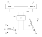
- FIG. 2 is a block diagram showing a control circuit of a shift operating system
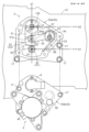
- FIG. 3 is a cross-sectional view showing an electric motor and a relay operating device that operate a trunnion shaft of the hydrostatic continuously variable transmission
- FIG. 4 is an explanatory diagram showing an electric motor and a relay operating device that operate a trunnion shaft of the hydrostatic continuously variable transmission
- FIG. 11 is a side view showing the neutral urging device showing a state in which the trunnion shaft is operated to a neutral position
- FIG. 11 is a side view showing the neutral urging device in a state where the trunnion shaft is operated to the maximum speed position on the forward side
- FIG. 4 is a side view showing the neutral urging device in a state where the trunnion shaft is operated to the maximum speed position on the reverse side
- FIG. 11 is a side view showing the neutral urging device in a state where the trunnion shaft is operated to the maximum speed position on the
- FIG. 1 is a side view showing the entire tractor, which is an example of a work vehicle equipped with a hydrostatic continuously variable transmission 12 according to an embodiment of the present invention.
- the tractor comprises a vehicle body 1 having left and right front wheels 1F steerable and drivable and left and right rear wheels 1R drivable.
- a driving unit 2 is provided in the front part of the vehicle body 1, and an operation part 3 with an operation cabin 30 is provided in the rear part of the vehicle body 1.
- the vehicle body 1 includes a vehicle body frame 10 that supports the driving section 2 and the driving section 3 on the front wheels 1F and the rear wheels 1R.
- the vehicle body frame 10 includes an engine mounting frame 10F supported by the front wheels 1F, an engine 20 provided in the driving unit 2, a transmission case 11 having a front end connected to the rear of the engine 20, and a rear end of the transmission case 11. and a transmission case 13 having a front end connected to the rear end of the hydrostatic continuously variable transmission 12 .
- the transmission case 13 is supported by the rear wheels 1R.
- a link mechanism 15 having a pair of left and right lift arms 14 provided at the rear portion of the transmission case 13 so as to be capable of swinging up and down, and a power take-off shaft 16 provided at the rear portion of the body frame 10 are provided.
- this tractor can connect a working device such as a rotary tillage device (not shown) to the rear portion of the vehicle body via a link mechanism 15 so as to be able to move up and down. It is configured to be able to transmit the driving force from the rotary tillage device (not shown)
- a driver's seat 31 In the operation cabin 30 of the operation unit 3, there are a driver's seat 31, a steering handle 32 as a control operation tool, a main shift lever 33 as a shift operation tool, a shuttle lever 34 as a forward/reverse shift operation tool, and the like. Equipped with various operating tools.
- the main shift lever 33 is arranged in front of the left rear wheel fender 37 among the left and right rear wheel fenders 37, and is arranged so that the driver can operate it while sitting on the driver's seat 31.
- the shuttle lever 34 is provided on the left side of a handle post 38 to which the steering handle 32 is attached, and is provided so that the driver sitting on the driver's seat 31 can operate it with his left hand.
- the hydrostatic continuously variable transmission 12 to which the power of the engine 20 is transmitted includes an axial plunger type hydraulic pump (not shown) and a hydraulic motor (not shown).
- the swash plate angle (not shown) of the hydraulic pump By adjusting the swash plate angle (not shown) of the hydraulic pump, the rotational speed of the output shaft (not shown) output from the hydraulic motor (not shown) is changed. It is configured to transmit the speed-changed power of the output shaft to the transmission case 13 .
- the swash plate angle of the hydraulic pump is changed by rotating a trunnion shaft 12b projecting laterally outward from an outer wall 12a of the hydrostatic continuously variable transmission 12 in forward and reverse directions. Rotating operation of the trunnion shaft 12b is performed by an electric motor 4, which functions as an electric actuator provided outside the hydrostatic continuously variable transmission 12 and which can rotate forward and backward.
- the main gear shift lever 33 and the shuttle lever 34 are operated by a detection signal of a volume (variable resistor) 33a provided at the swing fulcrum of the main gear lever 33 and a swing fulcrum of the shuttle lever 34.
- a detection signal from a volume (variable resistor) 34 a provided in the unit is detected, and the detection result is input to an ECU (electronic control unit) 35 .
- the ECU 35 is connected to a power supply section 36 and is supplied with control power from the power supply section 36 .
- a control signal from the ECU 35 is transmitted to the electric motor 4 by CAN communication.
- the electric motor 4 is supplied with electric power for driving from the power supply unit 36, and based on the control signal from the ECU 35, the trunnion shaft 12b is rotated in the forward and reverse directions to operate the hydrostatic continuously variable transmission. 12 change the swashplate angle.
- the main shift lever 33 is configured to be steplessly operable to any shift position between the lowest speed position Ls, which is zero speed, and the highest speed position Hs.
- the operating position of the main shift lever 33 is detected by a volume 33a of the main shift lever 33, and this detection signal is input to the ECU 35 as a commanded speed signal.
- the shuttle lever 34 is not stepless, but is configured so that the operation position can be switched among three preset positions of a forward position FF, a neutral position NN, and a reverse position RR.
- a volume 34a of the shuttle lever 34 detects to which of the three positions the shuttle lever 34 has been switched.
- a detection signal of the operation position of the volume 34a is input to the ECU 35 as a signal indicating the instructed traveling direction.
- the ECU 35 obtains the instructed forward or reverse travel speed from the detection signal of the volume 33a that detects the operating position of the main shift lever 33 and the detection signal of the volume 34a that detects the operating position of the shuttle lever 34.
- a control signal is output to the electric motor 4 so that the The electric motor 4 rotates the trunnion shaft 12b forward and backward based on a control signal from the ECU 35, and hydrostatic pressure is applied so that the trunnion shaft 12b is driven at the commanded driving speed in the commanded traveling direction. It controls the operation of the continuously variable transmission 12 .
- the relay operating device 5 is attached to the outer wall 12a on the right lateral side of the hydrostatic continuously variable transmission 12. As shown in FIGS. The relay operation device 5 is for transmitting the speed change operation by the electric motor 4 to the hydrostatic continuously variable transmission 12, and is constructed as follows.
- the relay operating device 5 links the speed change operation shaft 41 provided in the electric motor 4 with the trunnion shaft 12 b of the hydrostatic continuously variable transmission 12 to shift the speed of the electric motor 4 .
- Backlash occurs at a linking mechanism 5A that transmits an operation to the trunnion shaft 12b, and at a meshing point between a driving gear 42 (corresponding to a first gear) and a driven gear 52 (corresponding to a second gear) provided in the linking mechanism 5A. and an urging mechanism 5B for suppressing.
- the linking mechanism 5A and the biasing mechanism 5B are housed in a common casing 50.
- the casing 50 is detachably fixed to the outer wall 12a of the hydrostatic continuously variable transmission 12 using fixing tools such as stop bolts 17.
- fixing tools such as stop bolts 17.
- the linking mechanism 5A includes a drive gear 42 as a first linking portion G1 linked to a speed change operation shaft 41 configured by the output shaft of the electric motor 4, and a driven gear 52 as a second linking portion G2 linked to the trunnion shaft 12b. and have.
- the electric motor 4 includes a motor case 40 in which a rotor and a stator are housed, and a shift operation shaft 41 projecting from the motor case 40 .
- the motor case 40 is connected and fixed to the outside of a casing lid portion 50b of the casing 50, which will be described later.
- a shift operating shaft 41 protruding from the motor case 40 is installed in a state of penetrating the casing lid portion 50b and protruding into the casing main body 50a of the casing 50. As shown in FIG.
- the driving gear 42 is fitted on the gear shift operation shaft 41 so as to rotate forward and backward integrally with the axis P1 of the gear shift operation shaft 41 .
- a driven gear 52 meshing with the drive gear 42 is formed at the end of a swing arm 51 that swings integrally with the trunnion shaft 12b. That is, the swing arm 51 is mounted so as to swing integrally with the trunnion shaft 12b around the axis P2 of the trunnion shaft 12b.
- a gear having a pitch circle centered on the axis P2 of the trunnion shaft 12b is formed at the edge of the swing arm 51 at a position away from the axis P2 of the trunnion shaft 12b.
- the biasing mechanism 5B includes a swing arm 51 that swings integrally with the trunnion shaft 12b, and an operating body 55 that swings about an axis P3 parallel to the axis P2 of the trunnion shaft 12b.
- a cam 51 a for guiding a cam follower 56 provided on the operation body 55 is formed on the swing arm 51 .
- the cam 51a is formed at a location closer to the axis P2 of the trunnion shaft 12b than the location where the driven gear 52 is formed on the swing arm 51. As shown in FIG.
- the cam 51a is positioned between the axis P2 of the trunnion shaft 12b and the speed change operation shaft 41, as shown in FIGS. It is formed so as to be line symmetric with respect to the imaginary line segment a1 connecting with the axis P1.
- both the driven gear 52 and the cam 51a are formed at different positions in the axial direction of the trunnion shaft 12b. That is, as shown in FIGS. 3 and 4, the swing arm 51 is mounted on the trunnion shaft 12b and is constructed of a plate-like member extending toward the side where the speed change operation shaft 41 exists.
- the trunnion shaft 12b is a stepped plate material in which the plate thickness on the side closer to the axis P2 is thicker than the plate thickness on the side far from the axis P2.
- the cam 51a is formed at a stepped portion that serves as a boundary between a thick portion of the trunnion shaft 12b near the axis P2 and having a large thickness and a thin portion far from the axis P2 and having a small thickness.
- a driven gear 52 is formed at the edge portion of the swing arm 51, which is farther from the axis P2 of the trunnion shaft 12b than the cam 51a exists.
- the operating body 55 is supported by a shaft portion 53 having an axis P3 parallel to the axis P2 of the trunnion shaft 12b, and an eccentric ring portion 54 is formed integrally with the shaft portion 53.
- the operating body 55 is provided with a biasing spring 57 that biases the cam follower 56 toward the cam 51a.
- the urging spring 57 is composed of a torsion spring, and is mounted on the shaft portion 53 with its intermediate portion wound around the eccentric ring portion 54, one end portion wound around the shaft portion 56a of the cam follower 56, and the other end portion connected to the casing. It is in contact with the inner surface of the peripheral wall of 50 .
- the inner surface of the peripheral wall of the casing 50 receives a reaction force against the other end of the urging spring 57, and the one end of the urging spring 57 always urges the cam follower 56 against the cam 51a.
- the biasing force of the biasing spring 57 is not strong enough to forcibly swing the swing arm 51 to return the trunnion shaft 12b to the neutral position. It has an urging force to the extent that the swing arm 51 can swing by the amount of backlash.
- the axis P3 which is the swinging fulcrum of the operating body 55, is perpendicular to the imaginary line segment a1 connecting the axis P2 of the trunnion shaft 12b and the axis P1 of the shift operating shaft 41. It is provided within the space between a line segment b2 passing through the axis P2 of the trunnion shaft 12b and a line segment b1 passing through the axis P1 of the speed change operation shaft 41.
- the eccentric ring portion 54 formed integrally with the shaft portion 53 around the axis P3 the urging direction of the urging spring 57 mounted in a state in which the eccentric ring portion 54 is wound can be slightly adjusted. can be adjusted to fine tune the corresponding position of the cam follower 56 relative to the cam 51a.
- the casing 50 housing the linking mechanism 5A and the urging mechanism 5B includes a casing main body 50a having a peripheral wall portion and a lid-like casing lid portion 50b closing the open side of the casing body 50a. ing.
- the casing 50 is fixed to the hydrostatic continuously variable transmission 12 with the bottom of the casing main body 50 a facing the outer wall 12 a of the hydrostatic continuously variable transmission 12 .
- the electric motor 4 is fixed to the casing lid portion 50b and can be attached to and detached from the hydrostatic continuously variable transmission 12 together with the casing 50. As shown in FIG.
- a feedback volume (variable resistor) is attached to the casing lid portion 50b as a sensor 6 for detecting the rotational state of the trunnion shaft 12b.
- the sensor 6 can detect the swash plate angle of the hydrostatic continuously variable transmission 12 in real time by detecting the rotation angle of the trunnion shaft 12b that is rotated according to the change in the swing angle of the swing arm 51. It is like this.
- a detection signal corresponding to the detected rotation angle of the trunnion shaft 12 b is output to the ECU 35 as feedback information for detecting a change in the swash plate angle of the hydrostatic continuously variable transmission 12 .
- a part of the casing lid portion 50b is provided with an opening through which the inside of the casing 50 can be visually observed, or an internal viewing portion 58 made of a transparent portion.
- This internal visual observation part 58 is formed near the eccentric ring portion 54 and can be conveniently used when confirming the adjustment state by the eccentric ring portion 54 from the outside.
- the electric motor 4 moves the trunnion shaft 12b to the neutral position as shown in FIG. to operate.
- the direction of action of the biasing force f1 of the biasing spring 57 that biases the cam follower 56 of the relay operation device 5 toward the cam 51a is between the axis P2 of the trunnion shaft 12b and the axis P1 of the speed change operation shaft 41. It faces the side where the axis P2 of the trunnion shaft 12b exists at a position coinciding with the connecting line segment a1.
- the directions of the reaction forces of the cam 51a at the position contacting the cam follower 56 are the directions of the reaction forces f2 and f2 shown in FIG. Since the directions of action of the reaction forces f2 and f2 intersect each other at substantially the same angle in opposite directions across the line segment a1, the swing arm 51 also rotates clockwise around the axis P2 of the trunnion shaft 12b. It does not swing counterclockwise and is kept in a neutral position.
- the cam follower 56 is swung relatively to the right, contrary to the direction of the reaction force f2 acting on the cam follower 56 (to the left).
- the driven gear 52 on the rocking arm 51 side is moved in the direction fa in which it abuts against the tooth surface of the driving gear 42, and this position is maintained. state. That is, during forward traveling, the driven gear 52 on the swing arm 51 side is always driven in contact with the tooth surface of the drive gear 42, and the vehicle is driven in a state in which almost no backlash occurs.
- the reaction force f2 acting on the cam follower 56 is directed relatively leftward, opposite to the direction (rightward).
- the driven gear 52 on the side of the swing arm 51 is moved in the direction fa in which it contacts the tooth surface of the driving gear 42, and this position is reached. is maintained.
- the driven gear 52 on the swing arm 51 side is always driven in contact with the tooth surface of the driving gear 42, and the vehicle is driven with almost no backlash.
- the single drive gear 42 is provided in the first linking portion G1 linked to the shift operation shaft 41, and the single driven gear is provided in the second linking portion G2 linked to the trunnion shaft 12b.
- the structure provided with 52 is shown as an example, it is not necessarily limited to this structure.
- the first linking portion G1 may be provided with a plurality of gears
- the second linking portion G2 may be provided with a plurality of gears
- both the first linking portion G1 and the second linking portion G2 may be provided with a plurality of gears. may be provided.
- Other configurations may employ configurations similar to those of the above-described embodiment.
- the swing arm 51 swinging integrally with the trunnion shaft 12b is provided with the cam 51a, and the operation body 55 is provided with the cam follower 56.
- the structure is not necessarily limited to this structure. not something.
- a structure in which the swing arm 51 is provided with the cam follower 56 and the operation body 55 is provided with the cam 51a may be employed.
- Other configurations may employ configurations similar to those of the above-described embodiment.
- the structure in which the driven gear 52 and the cam 51a are formed on the swing arm 51 that swings integrally with the trunnion shaft 12b was illustrated, but the structure is not necessarily limited to this structure.
- the driven gear 52 is attached to a member different from the swing arm 51, or the driven gear 52 is directly attached to the trunnion shaft 12b and the cam 51a is formed on the swing arm 51 separately provided. Any suitable structure can be employed. Other configurations may employ configurations similar to those of the above-described embodiment.
- a line segment b2 passing through the axis P2 of the trunnion shaft 12b and the axis P1 of the shift operation shaft 41 are arranged in a direction orthogonal to the virtual line segment a1 connecting the trunnion shaft 12b and the shift operation shaft 41.
- the structure in which the shaft center P3 serving as the swinging fulcrum of the operating body 55 is provided within the interval from the line segment b1 passing through is illustrated, the structure is not necessarily limited to this structure.
- the axis P3, which is the swinging fulcrum of the operating body 55 may be provided at a position outside the interval between the line segment b2 and the line segment b1.
- Other configurations may employ configurations similar to those of the above-described embodiment.
- the structure in which the biasing mechanism 5B is housed in the casing 50 and the electric motor 4 is supported by the casing 50 is illustrated, but the structure is not necessarily limited to this structure.
- the casing 50 that houses the biasing mechanism 5B may not be provided, and the biasing mechanism 5B and the electric motor 4 may be appropriately stored in the space inside the machine body.
- Other configurations may employ configurations similar to those of the above-described embodiment.
- the casing 50 of the relay operating device 5 is attached to the outer wall 12a of the hydrostatic continuously variable transmission 12, and the sensor 6 for detecting the swash plate angle of the hydrostatic continuously variable transmission 12 is provided.
- the structure supported by the casing 50 is illustrated, it is not necessarily limited to this structure.
- the casing 50 of the relay operation device 5 may be attached to a location other than the outer wall 12a of the hydrostatic continuously variable transmission 12.
- the sensor 6 is supported by the outer wall 12a of the hydrostatic continuously variable transmission 12 so as to be able to detect the rotation angle of the trunnion shaft 12b at a position different from the casing 50.
- the swash plate angle of the continuously variable transmission 12 may be detected.
- Other configurations may employ configurations similar to those of the above-described embodiment.
- the urging spring 57 has a structure using a torsion spring inside the casing 50, but the urging spring 57 is not limited to a torsion spring, and may be a coil spring or the like. You can adopt anything. Other configurations may employ configurations similar to those of the above-described embodiment.
- the pump of the hydrostatic continuously variable transmission 12 has a structure in which it is a main transmission provided in the tractor, but it is not necessarily limited to this structure.
- it may be a transmission mechanism other than the main transmission mechanism provided in the tractor.
- the motor of the hydrostatic continuously variable transmission 12 may be used as an auxiliary transmission mechanism provided in the tractor.
- Other configurations may employ configurations similar to those of the above-described embodiment.
- the present invention can be applied to various work vehicles such as tractors, combine harvesters, rice transplanters, and trucks as work vehicles having a neutral operating device in an operation system from an electric motor to a hydrostatic continuously variable transmission.
Landscapes
- Engineering & Computer Science (AREA)
- General Engineering & Computer Science (AREA)
- Mechanical Engineering (AREA)
- Chemical & Material Sciences (AREA)
- Combustion & Propulsion (AREA)
- Transportation (AREA)
- Control Of Fluid Gearings (AREA)
- Gear-Shifting Mechanisms (AREA)
Abstract
作業車は、動力出力用の静油圧式無段変速装置12と、変速操作用の電動モータ4と、電動モータ4の変速操作軸41と静油圧式無段変速装置12のトラニオン軸12bとを連係する連係機構5Aと、が備えられ、連係機構5Aに、変速操作軸41に連係する第一連係部G1と、トラニオン軸12bに連係する第二連係部G2と、が備えられ、第一連係部G1に備えた第一ギヤ42に対して噛合する第二連係部G2の第二ギヤ52を、第一ギヤ42の回転方向とは逆の回転方向において、歯面同士が当接するように第一ギヤ42に押しつけ付勢する付勢機構5Bが備えられている。
Description
本発明は、静油圧式無段変速装置のトラニオン軸を電動モータで変速制御するようにした作業車に関する。
この種の作業車としては、電動モータの出力部に備えた駆動ギヤに対して、中継用のクランクレバーに備えた従動ギヤ部分を噛合させて、電動モータの出力により静油圧式無段変速装置のトラニオン軸を正逆に操作するようにした構造のものがある(例えば、特許文献1参照)。
特許文献1に記載された先行技術のように、電動モータからの出力でトラニオン軸の操作を行う構造のものでは、例えば、油圧アクチュエータを用いてトラニオン軸の操作を行う構造のものに比べて、圧油のリーク等によって操作位置の不安定さを招く虞が少ない点で有利である。
しかしながら、電動モータを用いた場合には、操作速度を減速するために用いるギヤ噛合箇所でのバックラッシュによる位置の不安定さや、フィードバックの感度によってはチャタリングが発生するなどの問題がある点で改善の余地がある。このようなギヤ噛合箇所でのバックラッシュ発生を回避するための手段として、例えば二枚重ねにした特殊構造のギヤを用いた場合には、組付け分解時の調整の煩わしさや、構造の複雑さを招くなどの問題がある。
しかしながら、電動モータを用いた場合には、操作速度を減速するために用いるギヤ噛合箇所でのバックラッシュによる位置の不安定さや、フィードバックの感度によってはチャタリングが発生するなどの問題がある点で改善の余地がある。このようなギヤ噛合箇所でのバックラッシュ発生を回避するための手段として、例えば二枚重ねにした特殊構造のギヤを用いた場合には、組付け分解時の調整の煩わしさや、構造の複雑さを招くなどの問題がある。
本発明は、電動モータから静油圧式無段変速装置のトラニオン軸への操作系に設けたギヤ噛合箇所でのバックラッシュ発生を簡単な構造で抑制して、安定した変速操作を行い得る作業車を提供しようとするものである。
本発明の作業車は、
動力出力用の静油圧式無段変速装置と、
変速操作用の電動モータと、
前記電動モータの変速操作軸と前記静油圧式無段変速装置のトラニオン軸とを連係する連係機構と、が備えられ、
前記連係機構に、第一ギヤを有し、前記変速操作軸に連係する第一連係部と、前記第一ギヤに対して噛合する第二ギヤを有し、前記トラニオン軸に連係する第二連係部と、が備えられ、
前記第一ギヤの回転方向とは逆の回転方向において前記第一ギヤの歯面と前記第二ギヤの歯面が当接するように、前記第二ギヤを前記第一ギヤに押しつけ付勢する付勢機構が備えられたものである。
動力出力用の静油圧式無段変速装置と、
変速操作用の電動モータと、
前記電動モータの変速操作軸と前記静油圧式無段変速装置のトラニオン軸とを連係する連係機構と、が備えられ、
前記連係機構に、第一ギヤを有し、前記変速操作軸に連係する第一連係部と、前記第一ギヤに対して噛合する第二ギヤを有し、前記トラニオン軸に連係する第二連係部と、が備えられ、
前記第一ギヤの回転方向とは逆の回転方向において前記第一ギヤの歯面と前記第二ギヤの歯面が当接するように、前記第二ギヤを前記第一ギヤに押しつけ付勢する付勢機構が備えられたものである。
本発明によると、電動モータの変速操作軸と静油圧式無段変速装置のトラニオン軸とを連係する連係機構に第一ギヤと第二ギヤとが備えられ、その第一ギヤと第二ギヤとの間で、歯面同士が当接するように付勢する付勢機構が備えられている。
したがって、二枚重ねのギヤ伝動機構などの複雑な構造を要することなく、第一ギヤと第二ギヤとを、常に歯面同士が当接する状態にして変速操作でき、電動モータの変速操作軸から静油圧式無段変速装置のトラニオン軸への操作を安定良く行わせることができる利点がある。
したがって、二枚重ねのギヤ伝動機構などの複雑な構造を要することなく、第一ギヤと第二ギヤとを、常に歯面同士が当接する状態にして変速操作でき、電動モータの変速操作軸から静油圧式無段変速装置のトラニオン軸への操作を安定良く行わせることができる利点がある。
本発明において、
前記付勢機構に、前記トラニオン軸と一体に揺動する揺動アームと、前記トラニオン軸の軸心と平行な軸心回りで揺動作動する操作体と、が備えられ、
前記揺動アームにカムが備えられ、
前記操作体にカムフォロワが備えられ、
前記カムフォロワを前記カムに向けて付勢する付勢バネが備えられ、
前記付勢バネ及び前記カムフォロワによる前記カムへの押圧作用に伴う前記揺動アームの揺動方向が、前記第二ギヤの歯面を前記第一ギヤの歯面に近づける方向であると好適である。
前記付勢機構に、前記トラニオン軸と一体に揺動する揺動アームと、前記トラニオン軸の軸心と平行な軸心回りで揺動作動する操作体と、が備えられ、
前記揺動アームにカムが備えられ、
前記操作体にカムフォロワが備えられ、
前記カムフォロワを前記カムに向けて付勢する付勢バネが備えられ、
前記付勢バネ及び前記カムフォロワによる前記カムへの押圧作用に伴う前記揺動アームの揺動方向が、前記第二ギヤの歯面を前記第一ギヤの歯面に近づける方向であると好適である。
本構成によれば、トラニオン軸と一体に揺動する揺動アームと、トラニオン軸の軸心と平行な軸心回りで揺動作動する操作体と、を備えるとともに、揺動アームに備えたカムに向けて、操作体に備えられたカムフォロワを付勢する付勢バネを備えるだけの簡単な構造で付勢機構を構成することができる。
本発明において、前記第二ギヤと前記カムとは、前記トラニオン軸の軸心方向での位置が互いに異なる箇所において、前記揺動アームに形成されていると好適である。
本構成によると、揺動アーム自体に第二ギヤとカムとの両方が形成されることで、部品点数が少なくて済み、かつ配設のための平面的な面積も少なくて済む。
本発明において、前記トラニオン軸と前記変速操作軸とを結ぶ仮想線分に直交する方向において、前記トラニオン軸の軸心を通る線分と、前記変速操作軸の軸心を通る線分との間隔内に、前記操作体の揺動支点が設けられていると好適である。
本構成によると、操作体に備えたカムフォロワと揺動アームに備えたカムとが効果的に作用し得るとともに、付勢機構をまとまりよくコンパクトに配設し易い。
本発明において、前記静油圧式無段変速装置の外壁に、前記連係機構及び前記付勢機構を内装するケーシングが取り付けられていると好適である。
本構成によると、静油圧式無段変速装置の外壁を、連係機構や付勢機構を内装するケーシングの取付手段として利用することができる。
本発明において、前記電動モータは前記ケーシングの外部で前記ケーシングに支持されていると好適である。
本構成によると、連係機構や付勢機構を内装するためのケーシングを、電動モータの支持手段として利用し、構造の簡素化を図り易い。
本発明において、前記静油圧式無段変速装置の斜板角度を検出するセンサが前記ケーシングに支持されていると好適である。
本構成によると、ケーシングをセンサの支持手段として利用できる。
本発明において、前記付勢機構に、前記トラニオン軸の軸心と平行な軸心回りで揺動作動する操作体が備えられ、
前記操作体に備えたカムフォロワを、前記トラニオン軸と一体に揺動する揺動アームに形成されたカムに向けて付勢する付勢バネが備えられ、
前記付勢バネは、前記操作体を支持する軸部に巻回された状態で、前記ケーシングに内装されたトーションバネであると好適である。
前記操作体に備えたカムフォロワを、前記トラニオン軸と一体に揺動する揺動アームに形成されたカムに向けて付勢する付勢バネが備えられ、
前記付勢バネは、前記操作体を支持する軸部に巻回された状態で、前記ケーシングに内装されたトーションバネであると好適である。
本構成によると、付勢バネとして、操作体を支持する軸部に巻回された状態でケーシングに内装されたトーションバネを用いることにより、付勢機構の構造を、比較的コンパクトで、かつ簡素に構成し易い。
本発明において、前記トーションバネは、前記カムフォロワに作用する反力を受ける側の端部が前記ケーシングに支持されていると好適である。
本構成によると、ケーシングをトーションバネの反力受けに利用して、構造の簡素化を図り得る。
本発明において、前記静油圧式無段変速装置のポンプが、トラクタに備えた主変速機構であり、前記トラニオン軸は、前記ポンプの斜板角度を変更するものであると好適である。
本構成によると、トラクタの主変速機構として静油圧式無段変速装置のポンプを用いることができる。
本発明において、前記静油圧式無段変速装置のモータが、前記トラクタに備えた副変速機構であると好適である。
本構成によると、トラクタの副変速機構として静油圧式無段変速装置のモータを用いることができる。
以下、本発明の作業車にかかる実施形態の一例を図面の記載に基づいて説明する。
尚、本実施形態での説明における前後方向及び左右方向は、特段の説明がない限り、次のように記載している。つまり、本発明を適用した作業車の作業走行時における前進側の進行方向(図1における矢印F参照)が「前」、後進側への進行方向(図1における矢印B参照)が「後」、その前後方向での前向き姿勢を基準としての右側に相当する方向(図3における矢印R参照)が「右」、同様に左側に相当する方向(図3における矢印L参照)が「左」である。
尚、本実施形態での説明における前後方向及び左右方向は、特段の説明がない限り、次のように記載している。つまり、本発明を適用した作業車の作業走行時における前進側の進行方向(図1における矢印F参照)が「前」、後進側への進行方向(図1における矢印B参照)が「後」、その前後方向での前向き姿勢を基準としての右側に相当する方向(図3における矢印R参照)が「右」、同様に左側に相当する方向(図3における矢印L参照)が「左」である。
〔全体構成〕
図1は、本発明の実施形態にかかる静油圧式無段変速装置12が装備された作業車の一例であるトラクタの全体を示す側面図である。この図に示すように、トラクタは、左及び右の前車輪1Fが操向及び駆動自在に装備され、左及び右の後車輪1Rが駆動自在に装備された車体1を備えている。車体1の前部に原動部2が設けられ、車体1の後部に運転キャビン30付きの運転部3が設けられている。車体1は、前車輪1F及び後車輪1Rに、原動部2及び運転部3を支持させる車体フレーム10を備えている。
図1は、本発明の実施形態にかかる静油圧式無段変速装置12が装備された作業車の一例であるトラクタの全体を示す側面図である。この図に示すように、トラクタは、左及び右の前車輪1Fが操向及び駆動自在に装備され、左及び右の後車輪1Rが駆動自在に装備された車体1を備えている。車体1の前部に原動部2が設けられ、車体1の後部に運転キャビン30付きの運転部3が設けられている。車体1は、前車輪1F及び後車輪1Rに、原動部2及び運転部3を支持させる車体フレーム10を備えている。
車体フレーム10は、前車輪1Fに支持されたエンジン搭載フレーム10Fと、原動部2が備えるエンジン20と、エンジン20の後部に前端部が連結された伝動ケース11と、伝動ケース11の後端部に前端部が連結された静油圧式無段変速装置12と、静油圧式無段変速装置12の後端部に前端部が連結されたミッションケース13と、を備えるモノコック構造となっている。
ミッションケース13は後車輪1Rに支持されている。このミッションケース13の後部に揺動昇降操作自在に設けた左右一対のリフトアーム14を有したリンク機構15、及び車体フレーム10の後部に設けた動力取り出し軸16が備えられている。
ミッションケース13は後車輪1Rに支持されている。このミッションケース13の後部に揺動昇降操作自在に設けた左右一対のリフトアーム14を有したリンク機構15、及び車体フレーム10の後部に設けた動力取り出し軸16が備えられている。
このトラクタは、たとえば車体後部にリンク機構15を介してロータリ耕耘装置(図示せず)等の作業装置を昇降操作可能に連結することができ、かつ、連結されたロータリ耕耘装置に動力取り出し軸16から駆動力を伝達することができるように構成されている。
運転部3の運転キャビン30内には、運転座席31、及び操縦操作具としてのステアリングハンドル32の他、変速操作具としての主変速レバー33、及び前後進変速操作具としてのシャトルレバー34等の各種操作具が配備されている。
主変速レバー33は、左右の後輪フェンダ37のうちの、左側の後輪フェンダ37の前面に配設され、運転座席31に塔座した姿勢で運転者が操作可能であるように配設されている。シャトルレバー34は、ステアリングハンドル32を取り付けたハンドルポスト38の左側部に装備されており、運転座席31に塔座した姿勢の運転者が左手で操作可能であるように設けてある。
主変速レバー33は、左右の後輪フェンダ37のうちの、左側の後輪フェンダ37の前面に配設され、運転座席31に塔座した姿勢で運転者が操作可能であるように配設されている。シャトルレバー34は、ステアリングハンドル32を取り付けたハンドルポスト38の左側部に装備されており、運転座席31に塔座した姿勢の運転者が左手で操作可能であるように設けてある。
〔変速制御系〕
エンジン20の動力が伝えられる静油圧式無段変速装置12では、アキシャルプランジャ型の油圧ポンプ(図外)及び油圧モータ(図外)を備えている。油圧ポンプの斜板角(図外)が変更調節されることにより油圧モータ(図外)から出力される出力軸(図外)の回転数が変更される。この出力軸の変速された動力をミッションケース13に伝達するように構成されている。
油圧ポンプの斜板角の変更は、静油圧式無段変速装置12の外壁12aから横外方へ突出するトラニオン軸12bの正逆方向の回動操作によって行われる。トラニオン軸12bの回動操作は、静油圧式無段変速装置12の外部に設けた電動アクチュエータとしての正逆転可能な電動モータ4によって行われる。
エンジン20の動力が伝えられる静油圧式無段変速装置12では、アキシャルプランジャ型の油圧ポンプ(図外)及び油圧モータ(図外)を備えている。油圧ポンプの斜板角(図外)が変更調節されることにより油圧モータ(図外)から出力される出力軸(図外)の回転数が変更される。この出力軸の変速された動力をミッションケース13に伝達するように構成されている。
油圧ポンプの斜板角の変更は、静油圧式無段変速装置12の外壁12aから横外方へ突出するトラニオン軸12bの正逆方向の回動操作によって行われる。トラニオン軸12bの回動操作は、静油圧式無段変速装置12の外部に設けた電動アクチュエータとしての正逆転可能な電動モータ4によって行われる。
図2に示すように、主変速レバー33及びシャトルレバー34の操作は、主変速レバー33の揺動支点部に備えたボリューム(可変抵抗器)33aの検出信号、及びシャトルレバー34の揺動支点部に備えたボリューム(可変抵抗器)34aの検出信号、によって検出され、その検出結果がECU(電子制御ユニット)35に入力される。
ECU35は電源部36に接続されており、電源部36から制御用の電力が供給されている。ECU35からの制御信号がCAN通信によって電動モータ4に送信される。電動モータ4には電源部36からの駆動用の電力が供給されており、ECU35からの制御信号に基づいて、トラニオン軸12bを正逆方向に回動操作して、静油圧式無段変速装置12の斜板角度を変更する。
ECU35は電源部36に接続されており、電源部36から制御用の電力が供給されている。ECU35からの制御信号がCAN通信によって電動モータ4に送信される。電動モータ4には電源部36からの駆動用の電力が供給されており、ECU35からの制御信号に基づいて、トラニオン軸12bを正逆方向に回動操作して、静油圧式無段変速装置12の斜板角度を変更する。
主変速レバー33は、零速となる最低速位置Lsから、最高速位置Hsまでの間で、任意の変速位置に無段階で変速操作可能に構成されている。主変速レバー33の操作位置は、主変速レバー33のボリューム33aで検出され、この検出信号が指令された速度信号としてECU35に入力される。
シャトルレバー34は、無段階ではなく、前進位置FF、中立位置NN、後進位置RR、の予め設定された三位置に操作位置を切り換え可能に構成されている。シャトルレバー34が上記三位置のうちの何れの操作位置に切り換えられたかが、シャトルレバー34のボリューム34aで検出される。このボリューム34aでの操作位置の検出信号が指令された進行方向を示す信号としてECU35に入力される。
シャトルレバー34は、無段階ではなく、前進位置FF、中立位置NN、後進位置RR、の予め設定された三位置に操作位置を切り換え可能に構成されている。シャトルレバー34が上記三位置のうちの何れの操作位置に切り換えられたかが、シャトルレバー34のボリューム34aで検出される。このボリューム34aでの操作位置の検出信号が指令された進行方向を示す信号としてECU35に入力される。
ECU35では、主変速レバー33の操作位置を検出したボリューム33aの検出信号と、シャトルレバー34の操作位置を検出したボリューム34aの検出信号から、指令された前進側又は後進側での走行速度が得られるように、電動モータ4に対して制御信号を出力する。
電動モータ4では、ECU35からの制御信号に基づいて、トラニオン軸12bを正逆方向に回動操作して、指令された駆動速度で指令された進行方向への駆動が行われるように、静油圧式無段変速装置12の作動を制御する。
電動モータ4では、ECU35からの制御信号に基づいて、トラニオン軸12bを正逆方向に回動操作して、指令された駆動速度で指令された進行方向への駆動が行われるように、静油圧式無段変速装置12の作動を制御する。
〔中継操作装置〕
図1、図3、及び図4に示されるように、静油圧式無段変速装置12の右横側方の外壁12aに、中継操作装置5が取り付けられている。
この中継操作装置5は、電動モータ4による変速操作を静油圧式無段変速装置12に伝えるためのものであり、次のように構成されている。
図1、図3、及び図4に示されるように、静油圧式無段変速装置12の右横側方の外壁12aに、中継操作装置5が取り付けられている。
この中継操作装置5は、電動モータ4による変速操作を静油圧式無段変速装置12に伝えるためのものであり、次のように構成されている。
図3及び図4に示すように、中継操作装置5は、電動モータ4に備えた変速操作軸41と静油圧式無段変速装置12のトラニオン軸12bとを連係させて、電動モータ4の変速操作をトラニオン軸12bに伝える連係機構5Aと、その連係機構5Aに備えた駆動ギヤ42(第一ギヤに相当する)と従動ギヤ52(第二ギヤに相当する)との噛合箇所におけるバックラッシュ発生を抑制するための付勢機構5Bと、を備えている。
これらの連係機構5Aと付勢機構5Bとは、共通のケーシング50に内装されている。ケーシング50は、静油圧式無段変速装置12の外壁12aに対して止めボルト17等の固定具を用いて脱着可能に固定されている。
これらの連係機構5Aと付勢機構5Bとは、共通のケーシング50に内装されている。ケーシング50は、静油圧式無段変速装置12の外壁12aに対して止めボルト17等の固定具を用いて脱着可能に固定されている。
連係機構5Aは、電動モータ4の出力軸によって構成された変速操作軸41に連係する第一連係部G1としての駆動ギヤ42と、トラニオン軸12bに連係する第二連係部G2としての従動ギヤ52と、を備えている。
電動モータ4には、ローターやステータを内装するモータケース40と、モータケース40から突出する変速操作軸41と、が備えられている。モータケース40が、ケーシング50のうちの、後述するケーシング蓋部50bの外側に連結固定されている。モータケース40から突出する変速操作軸41が、ケーシング蓋部50bを貫いて、ケーシング50のうちの、ケーシング本体50a内部に突入する状態で設置されている。
電動モータ4には、ローターやステータを内装するモータケース40と、モータケース40から突出する変速操作軸41と、が備えられている。モータケース40が、ケーシング50のうちの、後述するケーシング蓋部50bの外側に連結固定されている。モータケース40から突出する変速操作軸41が、ケーシング蓋部50bを貫いて、ケーシング50のうちの、ケーシング本体50a内部に突入する状態で設置されている。
駆動ギヤ42は、変速操作軸41の軸心P1と一体に正逆回動するように、変速操作軸41に外嵌する状態で設けられている。そして、駆動ギヤ42に噛合する従動ギヤ52は、トラニオン軸12bと一体に揺動する揺動アーム51の端部に形成されている。つまり、揺動アーム51は、トラニオン軸12bの軸心P2回りで、トラニオン軸12bと一体に揺動するように装着してある。そして、トラニオン軸12bの軸心P2から離れた位置における揺動アーム51の端縁部分に、トラニオン軸12bの軸心P2を中心とするピッチ円を有したギヤが形成され、これが従動ギヤ52を構成している。
付勢機構5Bは、トラニオン軸12bと一体に揺動する揺動アーム51と、トラニオン軸12bの軸心P2と平行な軸心P3回りで揺動作動する操作体55と、を備えている。そして、揺動アーム51には、操作体55に備えるカムフォロワ56を案内するためのカム51aが形成されている。このカム51aは、揺動アーム51に従動ギヤ52が形成されている箇所よりも、トラニオン軸12bの軸心P2に近い箇所に形成されている。
カム51aは、静油圧式無段変速装置12のトラニオン軸12bが中立位置に位置している状態では、図4及び図5に示すように、トラニオン軸12bの軸心P2と変速操作軸41の軸心P1とを結ぶ仮想線分a1を境にした線対称であるように形成されている。
カム51aは、静油圧式無段変速装置12のトラニオン軸12bが中立位置に位置している状態では、図4及び図5に示すように、トラニオン軸12bの軸心P2と変速操作軸41の軸心P1とを結ぶ仮想線分a1を境にした線対称であるように形成されている。
上記の揺動アーム51は単一の部材で構成されているが、トラニオン軸12bの軸心方向での位置が互いに異なる箇所において、従動ギヤ52とカム51aとの両者が形成されている。つまり、揺動アーム51は、図3及び図4に示すように、トラニオン軸12bに装着され、変速操作軸41の存在する側へ向けて延出された板状の部材で構成されているのであるが、トラニオン軸12bの軸心P2に近い側の板厚が軸心P2から遠い側の板厚よりも厚い段付きの板材となっている。
そして、トラニオン軸12bの軸心P2に近く板厚が大である肉厚箇所と、軸心P2から遠く板厚が小である薄肉箇所との境界となる段差部分に前記カム51aが形成され、そのカム51aの存在箇所よりもトラニオン軸12bの軸心P2から遠い箇所であるところの、揺動アーム51の端縁部分に、従動ギヤ52が形成されている。
そして、トラニオン軸12bの軸心P2に近く板厚が大である肉厚箇所と、軸心P2から遠く板厚が小である薄肉箇所との境界となる段差部分に前記カム51aが形成され、そのカム51aの存在箇所よりもトラニオン軸12bの軸心P2から遠い箇所であるところの、揺動アーム51の端縁部分に、従動ギヤ52が形成されている。
操作体55は、トラニオン軸12bの軸心P2と平行な軸心P3を有した軸部53に支持されており、軸部53には偏心輪部分54が一体に形成されている。
操作体55には、カムフォロワ56をカム51aに向けて付勢する付勢バネ57が備えられている。付勢バネ57はトーションバネによって構成され、中間部が偏心輪部分54を巻回する状態で軸部53に装着され、一端部がカムフォロワ56の軸部56aに巻回され、他端部がケーシング50の周壁内面に当接している。
この構造により、ケーシング50の周壁内面が付勢バネ57の他端部に対する反力受けとなり、付勢バネ57の一端部がカムフォロワ56をカム51aに対して常に押し付ける方向に付勢している。
付勢バネ57の付勢力は、揺動アーム51を強制的に揺動させてトラニオン軸12bを中立に戻すほどの付勢力を有したものではなく、駆動ギヤ42と従動ギヤ52との間におけるバックラッシュ分だけ揺動アーム51を揺動させ得る程度の付勢力を有したものである。
操作体55には、カムフォロワ56をカム51aに向けて付勢する付勢バネ57が備えられている。付勢バネ57はトーションバネによって構成され、中間部が偏心輪部分54を巻回する状態で軸部53に装着され、一端部がカムフォロワ56の軸部56aに巻回され、他端部がケーシング50の周壁内面に当接している。
この構造により、ケーシング50の周壁内面が付勢バネ57の他端部に対する反力受けとなり、付勢バネ57の一端部がカムフォロワ56をカム51aに対して常に押し付ける方向に付勢している。
付勢バネ57の付勢力は、揺動アーム51を強制的に揺動させてトラニオン軸12bを中立に戻すほどの付勢力を有したものではなく、駆動ギヤ42と従動ギヤ52との間におけるバックラッシュ分だけ揺動アーム51を揺動させ得る程度の付勢力を有したものである。
操作体55の揺動支点となる軸心P3は、図4に示すように、トラニオン軸12bの軸心P2と変速操作軸41の軸心P1とを結ぶ仮想線分a1に直交する方向において、前記トラニオン軸12bの軸心P2を通る線分b2と、前記変速操作軸41の軸心P1を通る線分b1との間隔内に設けられている。
軸部53に一体に形成されている偏心輪部分54を軸心P3回りで回動させることにより、偏心輪部分54を巻回する状態で装着されている付勢バネ57の付勢方向を微調節し、カム51aに対するカムフォロワ56の対応位置を微調節することができる。
軸部53に一体に形成されている偏心輪部分54を軸心P3回りで回動させることにより、偏心輪部分54を巻回する状態で装着されている付勢バネ57の付勢方向を微調節し、カム51aに対するカムフォロワ56の対応位置を微調節することができる。
連係機構5A及び付勢機構5Bを内装するケーシング50は、図3及び図4に示すように、周壁部分を有したケーシング本体50aと、その開放側を閉塞する蓋状のケーシング蓋部50bを備えている。
図3に示すように、ケーシング本体50aの底部が静油圧式無段変速装置12の外壁12aに対向する状態で、ケーシング50が静油圧式無段変速装置12に固定される。電動モータ4はケーシング蓋部50bに固定されており、ケーシング50とともに静油圧式無段変速装置12に対して脱着することができる。
図3に示すように、ケーシング本体50aの底部が静油圧式無段変速装置12の外壁12aに対向する状態で、ケーシング50が静油圧式無段変速装置12に固定される。電動モータ4はケーシング蓋部50bに固定されており、ケーシング50とともに静油圧式無段変速装置12に対して脱着することができる。
ケーシング蓋部50bには、図3及び図4に示すように、トラニオン軸12bの回動状態を検出するためのセンサ6として、フィードバック用のボリューム(可変抵抗器)が装着されている。このセンサ6は、揺動アーム51の揺動角度変化にともなって回転操作されるトラニオン軸12bの回転角度を検出することで、静油圧式無段変速装置12の斜板角度をリアルタイムで検出できるようにしてある。このトラニオン軸12bの検出された回転角度に対応する検出信号が、静油圧式無段変速装置12の斜板角の変化を検出するフィードバック情報としてECU35に出力される。
また、ケーシング蓋部50bの一部には、図4に示すように、ケーシング50の内部を目視可能な開口、もしくは透明部分による内部目視部58が設けられている。この内部目視部58は、偏心輪部分54の近く位置に形成されており、偏心輪部分54による調節状態を外部から確認する際に便利に用いることができる。
〔中継操作装置の動作〕
図2及び図5乃至図7に基づいて、電動モータ4の変速操作をトラニオン軸12bに伝える際の、中継操作装置5での動作形態について説明する。
図2及び図5乃至図7に基づいて、電動モータ4の変速操作をトラニオン軸12bに伝える際の、中継操作装置5での動作形態について説明する。
主変速レバー33が最低速位置Lsに操作されている場合、又はシャトルレバー34が中立位置NNに操作されている場合には、電動モータ4は、図5に示すようにトラニオン軸12bを中立位置に操作する。
この状態において、中継操作装置5のカムフォロワ56をカム51aに向けて付勢する付勢バネ57付勢力f1の作用方向は、トラニオン軸12bの軸心P2と変速操作軸41の軸心P1とを結ぶ線分a1と合致する位置で、トラニオン軸12bの軸心P2が存在する側に向いている。
このとき、カムフォロワ56に当接する位置におけるカム51aの反力の方向は、図5に示す反力f2,f2の方向である。反力f2,f2の作用方向は、前記線分a1を挟んで互いに逆向きにほぼ等角度で交差しているので、揺動アーム51は、トラニオン軸12bの軸心P2回りで時計方向にも反時計方向にも揺動せず、中立位置に保たれる。
この状態において、中継操作装置5のカムフォロワ56をカム51aに向けて付勢する付勢バネ57付勢力f1の作用方向は、トラニオン軸12bの軸心P2と変速操作軸41の軸心P1とを結ぶ線分a1と合致する位置で、トラニオン軸12bの軸心P2が存在する側に向いている。
このとき、カムフォロワ56に当接する位置におけるカム51aの反力の方向は、図5に示す反力f2,f2の方向である。反力f2,f2の作用方向は、前記線分a1を挟んで互いに逆向きにほぼ等角度で交差しているので、揺動アーム51は、トラニオン軸12bの軸心P2回りで時計方向にも反時計方向にも揺動せず、中立位置に保たれる。
シャトルレバー34が前進位置FFに操作され、主変速レバー33が最低速位置Lsから最高速位置Hsに近づくように操作されている場合には、電動モータ4は、図6に示すように駆動ギヤ42を反時計回りに回動させ、これに伴って揺動アーム51が時計回りに揺動する。その結果、トラニオン軸12bも時計回りに回動して、静油圧式無段変速装置12の斜板角度を所定量変化させ、前進走行が行われる。
このとき、カムフォロワ56に当接する位置におけるカム51aの反力の方向は、図6に示す反力f2の方向である。
反力f2の作用方向は、前記線分a1の片側、図6中では左側に向いている。このとき、操作体55の軸心P3からカムフォロワ56までの距離は一定であるため、カムフォロワ56に作用している反力f2の向き(左方向)とは逆に、相対的に右方向へ揺動アーム51を引き寄せるように作用し、図中の拡大部分に示すように、揺動アーム51側の従動ギヤ52が駆動ギヤ42の歯面に当接する方向faに寄せられて、この位置を保つ状態となる。つまり、前進走行中は、常に揺動アーム51側の従動ギヤ52が駆動ギヤ42の歯面に当接した状態で駆動され、ほとんどバックラッシュが生じない状態で駆動される。
このとき、カムフォロワ56に当接する位置におけるカム51aの反力の方向は、図6に示す反力f2の方向である。
反力f2の作用方向は、前記線分a1の片側、図6中では左側に向いている。このとき、操作体55の軸心P3からカムフォロワ56までの距離は一定であるため、カムフォロワ56に作用している反力f2の向き(左方向)とは逆に、相対的に右方向へ揺動アーム51を引き寄せるように作用し、図中の拡大部分に示すように、揺動アーム51側の従動ギヤ52が駆動ギヤ42の歯面に当接する方向faに寄せられて、この位置を保つ状態となる。つまり、前進走行中は、常に揺動アーム51側の従動ギヤ52が駆動ギヤ42の歯面に当接した状態で駆動され、ほとんどバックラッシュが生じない状態で駆動される。
シャトルレバー34が後進位置RRに操作され、主変速レバー33が最低速位置Lsから最高速位置Hsに近づくように操作されている場合には、電動モータ4は、図7に示すように駆動ギヤ42を時計回りに回動させ、これに伴って揺動アーム51が反時計回りに揺動する。その結果、トラニオン軸12bも反時計回りに回動して、静油圧式無段変速装置12の斜板角度を所定量変化させ、後進走行が行われる。
このとき、カムフォロワ56に当接する位置におけるカム51aの反力の方向は、図7に示す反力f2の方向である。
反力f2の作用方向は、前記線分a1の片側、図7中では右側に向いている。このとき、操作体55の軸心P3からカムフォロワ56までの距離は一定であるため、カムフォロワ56に作用している反力f2の向き(右方向)とは逆に、相対的に左方向へ向けて揺動アーム51を押すように作用し、図中の拡大部分に示すように、揺動アーム51側の従動ギヤ52が駆動ギヤ42の歯面に当接する方向faに寄せられて、この位置を保つ状態となる。つまり、後進走行中は、常に揺動アーム51側の従動ギヤ52が駆動ギヤ42の歯面に当接した状態で駆動され、ほとんどバックラッシュが生じない状態で駆動される。
このとき、カムフォロワ56に当接する位置におけるカム51aの反力の方向は、図7に示す反力f2の方向である。
反力f2の作用方向は、前記線分a1の片側、図7中では右側に向いている。このとき、操作体55の軸心P3からカムフォロワ56までの距離は一定であるため、カムフォロワ56に作用している反力f2の向き(右方向)とは逆に、相対的に左方向へ向けて揺動アーム51を押すように作用し、図中の拡大部分に示すように、揺動アーム51側の従動ギヤ52が駆動ギヤ42の歯面に当接する方向faに寄せられて、この位置を保つ状態となる。つまり、後進走行中は、常に揺動アーム51側の従動ギヤ52が駆動ギヤ42の歯面に当接した状態で駆動され、ほとんどバックラッシュが生じない状態で駆動される。
〔別実施形態〕
以下に、別実施形態を示す。下記の各別実施形態は、矛盾が生じない限り、複数組み合わせて用いてもよい。なお、本発明の範囲は、これらの実施形態の内容に限定されるものではない。
以下に、別実施形態を示す。下記の各別実施形態は、矛盾が生じない限り、複数組み合わせて用いてもよい。なお、本発明の範囲は、これらの実施形態の内容に限定されるものではない。
(1)上述した実施形態においては、変速操作軸41に連係する第一連係部G1に単一の駆動ギヤ42が設けられ、トラニオン軸12bに連係する第二連係部G2に単一の従動ギヤ52が設けられた構造のものを例示したが、必ずしもこの構造に限定されるものではない。
例えば、第一連係部G1に複数個のギヤを備えたり、第二連係部G2に複数個のギヤを備えたり、あるいは第一連係部G1と第二連係部G2との双方に複数個のギヤを備えたものであってもよい。
その他の構成は、前述した実施形態と同様の構成を採用すればよい。
例えば、第一連係部G1に複数個のギヤを備えたり、第二連係部G2に複数個のギヤを備えたり、あるいは第一連係部G1と第二連係部G2との双方に複数個のギヤを備えたものであってもよい。
その他の構成は、前述した実施形態と同様の構成を採用すればよい。
(2)実施形態では、トラニオン軸12bと一体に揺動する揺動アーム51にカム51aを備え、操作体55にカムフォロワ56が備えられた構造のものを例示したが、必ずしもこの構造に限定されるものではない。例えば、揺動アーム51にカムフォロワ56を備え、操作体55にカム51aが備えられた構造であってもよい。
その他の構成は、前述した実施形態と同様の構成を採用すればよい。
その他の構成は、前述した実施形態と同様の構成を採用すればよい。
(3)実施形態では、トラニオン軸12bと一体に揺動する揺動アーム51に、従動ギヤ52とカム51aが形成された構造のものを例示したが、必ずしもこの構造に限定されるものではない。例えば、従動ギヤ52を揺動アーム51とは別の部材に取り付ける、あるいは、従動ギヤ52をトラニオン軸12bに直接取り付けて、これとは別に備えた揺動アーム51にカム51aを形成するなど、適宜の構造を採用することができる。
その他の構成は、前述した実施形態と同様の構成を採用すればよい。
その他の構成は、前述した実施形態と同様の構成を採用すればよい。
(4)実施形態では、トラニオン軸12bと変速操作軸41とを結ぶ仮想線分a1に直交する方向において、トラニオン軸12bの軸心P2を通る線分b2と、変速操作軸41の軸心P1を通る線分b1との間隔内に、操作体55の揺動支点となる軸心P3が設けられた構造のものを例示したが、必ずしもこの構造に限定されるものではない。例えば、操作体55の揺動支点となる軸心P3が上記の線分b2と線分b1との間隔から外れた位置に設けられたものであってもよい。
その他の構成は、前述した実施形態と同様の構成を採用すればよい。
その他の構成は、前述した実施形態と同様の構成を採用すればよい。
(5)実施の形態では、付勢機構5Bがケーシング50に内装され、そのケーシング50に電動モータ4が支持された構造のものを例示したが、必ずしもこの構造に限定されるものではない。例えば、付勢機構5Bを内装するケーシング50を備えず、付勢機構5Bも電動モータ4も適宜機体内部の空間に格納したものであってもよい。
その他の構成は、前述した実施形態と同様の構成を採用すればよい。
その他の構成は、前述した実施形態と同様の構成を採用すればよい。
(6)実施の形態では、中継操作装置5のケーシング50が静油圧式無段変速装置12の外壁12aに取り付けられるとともに、静油圧式無段変速装置12の斜板角度を検出するセンサ6がケーシング50に支持された構造のものを例示したが、必ずしもこの構造に限定されるものではない。例えば、中継操作装置5のケーシング50を静油圧式無段変速装置12の外壁12a以外の箇所に取り付けたものであっても差し支えない。この場合、センサ6は、ケーシング50とは別の位置でトラニオン軸12bの回転角を検出可能であるように、静油圧式無段変速装置12の外壁12aに支持させる等して、静油圧式無段変速装置12の斜板角度を検出するようにしてもよい。
その他の構成は、前述した実施形態と同様の構成を採用すればよい。
その他の構成は、前述した実施形態と同様の構成を採用すればよい。
(7)実施の形態では、付勢バネ57として、ケーシング50に内装されたトーションバネを用いた構造のものを例示したが、付勢バネ57としては、トーションバネに限らずコイルバネなど、適宜のものを採用してもよい。
その他の構成は、前述した実施形態と同様の構成を採用すればよい。
その他の構成は、前述した実施形態と同様の構成を採用すればよい。
(8)実施の形態では、静油圧式無段変速装置12のポンプが、トラクタに備えた主変速機構である構造のものを採用したが、必ずしもこの構造に限定されるものではない。例えば、トラクタに備えた主変速機構以外の変速機構であっても差し支えない。
また、静油圧式無段変速装置12のモータが、トラクタに備えた副変速機構として用いられるものであっても差し支えない。
その他の構成は、前述した実施形態と同様の構成を採用すればよい。
また、静油圧式無段変速装置12のモータが、トラクタに備えた副変速機構として用いられるものであっても差し支えない。
その他の構成は、前述した実施形態と同様の構成を採用すればよい。
本発明は、電動モータから静油圧式無段変速装置に至る操作系に中立操作装置を備える作業車として、トラクタの他、コンバイン、田植機、運搬車など各種の作業車に適用し得る。
4 電動モータ
5A 連係機構
5B 付勢機構
6 センサ
12 静油圧式無段変速装置
12b トラニオン軸
41 変速操作軸
42 第一ギヤ(駆動ギヤ)
50 ケーシング
51 揺動アーム
51a カム
52 第二ギヤ(従動ギヤ)
55 操作体
56 カムフォロワ
57 付勢バネ
G1 第一連係部
G2 第二連係部
P1 軸心
P2 軸心
P3 軸心(揺動支点)
a1 仮想線分
b1 線分
b2 線分
5A 連係機構
5B 付勢機構
6 センサ
12 静油圧式無段変速装置
12b トラニオン軸
41 変速操作軸
42 第一ギヤ(駆動ギヤ)
50 ケーシング
51 揺動アーム
51a カム
52 第二ギヤ(従動ギヤ)
55 操作体
56 カムフォロワ
57 付勢バネ
G1 第一連係部
G2 第二連係部
P1 軸心
P2 軸心
P3 軸心(揺動支点)
a1 仮想線分
b1 線分
b2 線分
Claims (11)
- 動力出力用の静油圧式無段変速装置と、
変速操作用の電動モータと、
前記電動モータの変速操作軸と前記静油圧式無段変速装置のトラニオン軸とを連係する連係機構と、が備えられ、
前記連係機構に、前記変速操作軸に連係する第一連係部と、前記トラニオン軸に連係する第二連係部と、が備えられ、
前記第一連係部に備えた第一ギヤに対して噛合する前記第二連係部の第二ギヤを、前記第一ギヤの回転方向とは逆の回転方向において、歯面同士が当接するように前記第一ギヤに押しつけ付勢する付勢機構が備えられた作業車。 - 前記付勢機構に、前記トラニオン軸と一体に揺動する揺動アームと、前記トラニオン軸の軸心と平行な軸心回りで揺動作動する操作体と、が備えられ、
前記揺動アームにカムが備えられ、
前記操作体にカムフォロワが備えられ、
前記カムフォロワを前記カムに向けて付勢する付勢バネが備えられ、
前記付勢バネ及び前記カムフォロワによる前記カムへの押圧作用に伴う前記揺動アームの揺動方向が、前記第二ギヤの歯面を前記第一ギヤの歯面に近づける方向である請求項1記載の作業車。 - 前記第二ギヤと前記カムとは、前記トラニオン軸の軸心方向での位置が互いに異なる箇所において、前記揺動アームに形成されている請求項2記載の作業車。
- 前記トラニオン軸と前記変速操作軸とを結ぶ仮想線分に直交する方向において、前記トラニオン軸の軸心を通る線分と、前記変速操作軸の軸心を通る線分との間隔内に、前記操作体の揺動支点が設けられている請求項2又は3記載の作業車。
- 前記静油圧式無段変速装置の外壁に、前記連係機構及び前記付勢機構を内装するケーシングが取り付けられている請求項1~4のいずれか一項記載の作業車。
- 前記電動モータは前記ケーシングの外部で前記ケーシングに支持されている請求項5記載の作業車。
- 前記静油圧式無段変速装置の斜板角度を検出するセンサが前記ケーシングに支持されている請求項5又は6記載の作業車。
- 前記付勢機構に、前記トラニオン軸の軸心と平行な軸心回りで揺動作動する操作体が備えられ、
前記操作体に備えたカムフォロワを、前記トラニオン軸と一体に揺動する揺動アームに形成されたカムに向けて付勢する付勢バネが備えられ、
前記付勢バネは、前記操作体を支持する軸部に巻回された状態で、前記ケーシングに内装されたトーションバネである請求項5~7のいずれか一項記載の作業車。 - 前記トーションバネは、前記カムフォロワに作用する反力を受ける側の端部が前記ケーシングに支持されている請求項8記載の作業車。
- 前記静油圧式無段変速装置のポンプが、トラクタに備えた主変速機構であり、前記トラニオン軸は、前記ポンプの斜板角度を変更するものである請求項1~9のいずれか一項記載の作業車。
- 前記静油圧式無段変速装置のモータが、前記トラクタに備えた副変速機構である請求項10記載の作業車。
Priority Applications (2)
| Application Number | Priority Date | Filing Date | Title |
|---|---|---|---|
| EP22911225.5A EP4455516A4 (en) | 2021-12-24 | 2022-12-20 | WORK VEHICLE |
| US18/664,345 US20240295265A1 (en) | 2021-12-24 | 2024-05-15 | Work vehicle |
Applications Claiming Priority (2)
| Application Number | Priority Date | Filing Date | Title |
|---|---|---|---|
| JP2021211674A JP7542517B2 (ja) | 2021-12-24 | 2021-12-24 | 作業車 |
| JP2021-211674 | 2021-12-24 |
Related Child Applications (1)
| Application Number | Title | Priority Date | Filing Date |
|---|---|---|---|
| US18/664,345 Continuation US20240295265A1 (en) | 2021-12-24 | 2024-05-15 | Work vehicle |
Publications (1)
| Publication Number | Publication Date |
|---|---|
| WO2023120523A1 true WO2023120523A1 (ja) | 2023-06-29 |
Family
ID=86902519
Family Applications (1)
| Application Number | Title | Priority Date | Filing Date |
|---|---|---|---|
| PCT/JP2022/046884 Ceased WO2023120523A1 (ja) | 2021-12-24 | 2022-12-20 | 作業車 |
Country Status (4)
| Country | Link |
|---|---|
| US (1) | US20240295265A1 (ja) |
| EP (1) | EP4455516A4 (ja) |
| JP (1) | JP7542517B2 (ja) |
| WO (1) | WO2023120523A1 (ja) |
Citations (6)
| Publication number | Priority date | Publication date | Assignee | Title |
|---|---|---|---|---|
| JPH1054461A (ja) * | 1996-08-09 | 1998-02-24 | Kubota Corp | 作業機の無段変速装置 |
| JP2005155846A (ja) * | 2003-11-27 | 2005-06-16 | Iseki & Co Ltd | 油圧式変速装置 |
| JP2009150414A (ja) | 2007-12-18 | 2009-07-09 | Iseki & Co Ltd | 無段変速式作業車両 |
| JP2012031884A (ja) * | 2010-07-28 | 2012-02-16 | Kubota Corp | 静油圧式無段変速装置の中立付勢装置 |
| JP2012036774A (ja) * | 2010-08-04 | 2012-02-23 | Kanzaki Kokyukoki Manufacturing Co Ltd | 電動操作型油圧アクチュエータユニット及び油圧四輪駆動作業車輌 |
| US9114798B1 (en) * | 2012-12-12 | 2015-08-25 | Hydro-Gear Limited Partnership | Electric actuator for drive apparatus |
Family Cites Families (4)
| Publication number | Priority date | Publication date | Assignee | Title |
|---|---|---|---|---|
| FR1431758A (fr) * | 1965-01-28 | 1966-03-18 | Richier Sa | Dispositif de commande à distance, particulièrement applicable aux transmissions hydrauliques |
| US6321612B1 (en) * | 1998-04-14 | 2001-11-27 | Mannesmann Sachs Ag | Actuating mechanism for the automatic operation of a gear-shift in a transmission |
| JP4320994B2 (ja) * | 1999-10-27 | 2009-08-26 | 日本精工株式会社 | 変速機用電動駆動装置 |
| US7165398B1 (en) * | 2002-11-07 | 2007-01-23 | Hydro-Gear Limited Partnership | System and method for electronic actuation of axle driving apparatus |
-
2021
- 2021-12-24 JP JP2021211674A patent/JP7542517B2/ja active Active
-
2022
- 2022-12-20 WO PCT/JP2022/046884 patent/WO2023120523A1/ja not_active Ceased
- 2022-12-20 EP EP22911225.5A patent/EP4455516A4/en active Pending
-
2024
- 2024-05-15 US US18/664,345 patent/US20240295265A1/en active Pending
Patent Citations (6)
| Publication number | Priority date | Publication date | Assignee | Title |
|---|---|---|---|---|
| JPH1054461A (ja) * | 1996-08-09 | 1998-02-24 | Kubota Corp | 作業機の無段変速装置 |
| JP2005155846A (ja) * | 2003-11-27 | 2005-06-16 | Iseki & Co Ltd | 油圧式変速装置 |
| JP2009150414A (ja) | 2007-12-18 | 2009-07-09 | Iseki & Co Ltd | 無段変速式作業車両 |
| JP2012031884A (ja) * | 2010-07-28 | 2012-02-16 | Kubota Corp | 静油圧式無段変速装置の中立付勢装置 |
| JP2012036774A (ja) * | 2010-08-04 | 2012-02-23 | Kanzaki Kokyukoki Manufacturing Co Ltd | 電動操作型油圧アクチュエータユニット及び油圧四輪駆動作業車輌 |
| US9114798B1 (en) * | 2012-12-12 | 2015-08-25 | Hydro-Gear Limited Partnership | Electric actuator for drive apparatus |
Non-Patent Citations (1)
| Title |
|---|
| See also references of EP4455516A4 |
Also Published As
| Publication number | Publication date |
|---|---|
| US20240295265A1 (en) | 2024-09-05 |
| EP4455516A1 (en) | 2024-10-30 |
| JP2023095653A (ja) | 2023-07-06 |
| EP4455516A4 (en) | 2025-12-24 |
| JP7542517B2 (ja) | 2024-08-30 |
Similar Documents
| Publication | Publication Date | Title |
|---|---|---|
| JP4101083B2 (ja) | 作業車の走行変速制御装置 | |
| WO2010131576A1 (ja) | 作業車両の変速装置 | |
| EP3421283A1 (en) | Working vehicle | |
| JP4327362B2 (ja) | 車両の変速及び操向用伝動装置 | |
| JP3936854B2 (ja) | 作業車両の変速装置 | |
| JP5331569B2 (ja) | 作業車両の変速装置 | |
| JP3868257B2 (ja) | 作業車両の変速装置 | |
| JP2009270607A (ja) | 作業車の変速操作装置 | |
| JP7542517B2 (ja) | 作業車 | |
| JP3947640B2 (ja) | クローラ式走行車両 | |
| JP5771119B2 (ja) | 作業車 | |
| JP2025093793A (ja) | 作業車 | |
| JP2000025639A (ja) | 車両の操向駆動装置 | |
| JP2025093792A (ja) | 作業車 | |
| JP4779196B2 (ja) | 作業車両 | |
| JP4257100B2 (ja) | トラクタのpto駆動装置 | |
| JP5242534B2 (ja) | 変速操作機構 | |
| JPH1159209A (ja) | 歩行型管理機における無段変速操作装置 | |
| JP3773830B2 (ja) | 作業車両の非常用走行機構 | |
| JP5686471B2 (ja) | 作業車両 | |
| JP5809039B2 (ja) | 作業機 | |
| JP2000168383A (ja) | 作業車両の変速装置 | |
| JP2524654Y2 (ja) | 作業用走行機体における油圧ポンプの取付け構造 | |
| JP4826285B2 (ja) | 作業車両における変速操作装置 | |
| JP4519503B2 (ja) | 四輪駆動・前輪増速駆動切換機構 |
Legal Events
| Date | Code | Title | Description |
|---|---|---|---|
| 121 | Ep: the epo has been informed by wipo that ep was designated in this application |
Ref document number: 22911225 Country of ref document: EP Kind code of ref document: A1 |
|
| NENP | Non-entry into the national phase |
Ref country code: DE |
|
| ENP | Entry into the national phase |
Ref document number: 2022911225 Country of ref document: EP Effective date: 20240724 |