WO2023127049A1 - 基板処理モジュールおよびそれを備える基板処理装置 - Google Patents
基板処理モジュールおよびそれを備える基板処理装置 Download PDFInfo
- Publication number
- WO2023127049A1 WO2023127049A1 PCT/JP2021/048655 JP2021048655W WO2023127049A1 WO 2023127049 A1 WO2023127049 A1 WO 2023127049A1 JP 2021048655 W JP2021048655 W JP 2021048655W WO 2023127049 A1 WO2023127049 A1 WO 2023127049A1
- Authority
- WO
- WIPO (PCT)
- Prior art keywords
- chuck
- substrate
- tank
- substrate processing
- substrates
- Prior art date
- Legal status (The legal status is an assumption and is not a legal conclusion. Google has not performed a legal analysis and makes no representation as to the accuracy of the status listed.)
- Ceased
Links
Images








Classifications
-
- H—ELECTRICITY
- H10—SEMICONDUCTOR DEVICES; ELECTRIC SOLID-STATE DEVICES NOT OTHERWISE PROVIDED FOR
- H10P—GENERIC PROCESSES OR APPARATUS FOR THE MANUFACTURE OR TREATMENT OF DEVICES COVERED BY CLASS H10
- H10P72/00—Handling or holding of wafers, substrates or devices during manufacture or treatment thereof
- H10P72/70—Handling or holding of wafers, substrates or devices during manufacture or treatment thereof for supporting or gripping
- H10P72/76—Handling or holding of wafers, substrates or devices during manufacture or treatment thereof for supporting or gripping using mechanical means, e.g. clamps or pinches
- H10P72/7604—Handling or holding of wafers, substrates or devices during manufacture or treatment thereof for supporting or gripping using mechanical means, e.g. clamps or pinches the wafers being placed on a susceptor, stage or support
- H10P72/7624—Handling or holding of wafers, substrates or devices during manufacture or treatment thereof for supporting or gripping using mechanical means, e.g. clamps or pinches the wafers being placed on a susceptor, stage or support characterised by the mechanical construction of the susceptor, stage or support
-
- B—PERFORMING OPERATIONS; TRANSPORTING
- B08—CLEANING
- B08B—CLEANING IN GENERAL; PREVENTION OF FOULING IN GENERAL
- B08B3/00—Cleaning by methods involving the use or presence of liquid or steam
- B08B3/04—Cleaning involving contact with liquid
- B08B3/08—Cleaning involving contact with liquid the liquid having chemical or dissolving effect
-
- H—ELECTRICITY
- H10—SEMICONDUCTOR DEVICES; ELECTRIC SOLID-STATE DEVICES NOT OTHERWISE PROVIDED FOR
- H10P—GENERIC PROCESSES OR APPARATUS FOR THE MANUFACTURE OR TREATMENT OF DEVICES COVERED BY CLASS H10
- H10P72/00—Handling or holding of wafers, substrates or devices during manufacture or treatment thereof
- H10P72/04—Apparatus for manufacture or treatment
- H10P72/0402—Apparatus for fluid treatment
- H10P72/0406—Apparatus for fluid treatment for cleaning followed by drying, rinsing, stripping, blasting or the like
- H10P72/0411—Apparatus for fluid treatment for cleaning followed by drying, rinsing, stripping, blasting or the like for wet cleaning or washing
- H10P72/0414—Apparatus for fluid treatment for cleaning followed by drying, rinsing, stripping, blasting or the like for wet cleaning or washing using mainly spraying means, e.g. nozzles
-
- B—PERFORMING OPERATIONS; TRANSPORTING
- B08—CLEANING
- B08B—CLEANING IN GENERAL; PREVENTION OF FOULING IN GENERAL
- B08B13/00—Accessories or details of general applicability for machines or apparatus for cleaning
-
- H—ELECTRICITY
- H10—SEMICONDUCTOR DEVICES; ELECTRIC SOLID-STATE DEVICES NOT OTHERWISE PROVIDED FOR
- H10P—GENERIC PROCESSES OR APPARATUS FOR THE MANUFACTURE OR TREATMENT OF DEVICES COVERED BY CLASS H10
- H10P72/00—Handling or holding of wafers, substrates or devices during manufacture or treatment thereof
- H10P72/04—Apparatus for manufacture or treatment
- H10P72/0402—Apparatus for fluid treatment
- H10P72/0406—Apparatus for fluid treatment for cleaning followed by drying, rinsing, stripping, blasting or the like
- H10P72/0411—Apparatus for fluid treatment for cleaning followed by drying, rinsing, stripping, blasting or the like for wet cleaning or washing
- H10P72/0416—Apparatus for fluid treatment for cleaning followed by drying, rinsing, stripping, blasting or the like for wet cleaning or washing with the semiconductor substrates being dipped in baths or vessels
-
- H—ELECTRICITY
- H10—SEMICONDUCTOR DEVICES; ELECTRIC SOLID-STATE DEVICES NOT OTHERWISE PROVIDED FOR
- H10P—GENERIC PROCESSES OR APPARATUS FOR THE MANUFACTURE OR TREATMENT OF DEVICES COVERED BY CLASS H10
- H10P72/00—Handling or holding of wafers, substrates or devices during manufacture or treatment thereof
- H10P72/04—Apparatus for manufacture or treatment
- H10P72/0451—Apparatus for manufacturing or treating in a plurality of work-stations
- H10P72/0452—Apparatus for manufacturing or treating in a plurality of work-stations characterised by the layout of the process chambers
- H10P72/0456—Apparatus for manufacturing or treating in a plurality of work-stations characterised by the layout of the process chambers in-line arrangement
-
- H—ELECTRICITY
- H10—SEMICONDUCTOR DEVICES; ELECTRIC SOLID-STATE DEVICES NOT OTHERWISE PROVIDED FOR
- H10P—GENERIC PROCESSES OR APPARATUS FOR THE MANUFACTURE OR TREATMENT OF DEVICES COVERED BY CLASS H10
- H10P72/00—Handling or holding of wafers, substrates or devices during manufacture or treatment thereof
- H10P72/30—Handling or holding of wafers, substrates or devices during manufacture or treatment thereof for conveying, e.g. between different workstations
- H10P72/32—Handling or holding of wafers, substrates or devices during manufacture or treatment thereof for conveying, e.g. between different workstations between different workstations
- H10P72/3212—Handling or holding of wafers, substrates or devices during manufacture or treatment thereof for conveying, e.g. between different workstations between different workstations the substrates to be conveyed not being semiconductor wafers or large planar substrates, e.g. chips or lead frames
-
- H—ELECTRICITY
- H10—SEMICONDUCTOR DEVICES; ELECTRIC SOLID-STATE DEVICES NOT OTHERWISE PROVIDED FOR
- H10P—GENERIC PROCESSES OR APPARATUS FOR THE MANUFACTURE OR TREATMENT OF DEVICES COVERED BY CLASS H10
- H10P72/00—Handling or holding of wafers, substrates or devices during manufacture or treatment thereof
- H10P72/30—Handling or holding of wafers, substrates or devices during manufacture or treatment thereof for conveying, e.g. between different workstations
- H10P72/33—Handling or holding of wafers, substrates or devices during manufacture or treatment thereof for conveying, e.g. between different workstations into and out of processing chamber
- H10P72/3312—Vertical transfer of a batch of workpieces
-
- H—ELECTRICITY
- H10—SEMICONDUCTOR DEVICES; ELECTRIC SOLID-STATE DEVICES NOT OTHERWISE PROVIDED FOR
- H10P—GENERIC PROCESSES OR APPARATUS FOR THE MANUFACTURE OR TREATMENT OF DEVICES COVERED BY CLASS H10
- H10P72/00—Handling or holding of wafers, substrates or devices during manufacture or treatment thereof
- H10P72/70—Handling or holding of wafers, substrates or devices during manufacture or treatment thereof for supporting or gripping
- H10P72/76—Handling or holding of wafers, substrates or devices during manufacture or treatment thereof for supporting or gripping using mechanical means, e.g. clamps or pinches
- H10P72/7604—Handling or holding of wafers, substrates or devices during manufacture or treatment thereof for supporting or gripping using mechanical means, e.g. clamps or pinches the wafers being placed on a susceptor, stage or support
- H10P72/7612—Handling or holding of wafers, substrates or devices during manufacture or treatment thereof for supporting or gripping using mechanical means, e.g. clamps or pinches the wafers being placed on a susceptor, stage or support characterised by lifting arrangements, e.g. lift pins
Definitions
- the present invention relates to a substrate processing module for processing substrates and a substrate processing apparatus including the same.
- Patent Document 1 discloses a substrate processing apparatus in which a plurality of pairs of chemical liquid tanks and cleaning tanks are arranged in the longitudinal direction of the apparatus, and which has a main transport mechanism and a sub-transport mechanism.
- a main transport mechanism longitudinally moves a plurality of substrates from one end of the apparatus to the other end thereof.
- the sub-transport mechanism moves the plurality of substrates in the longitudinal direction and the vertical direction within the range of the pair of chemical bath and cleaning bath.
- An object of the present invention is to improve the throughput of a substrate processing apparatus that processes substrates using a plurality of tanks by increasing the operation rate of each of the plurality of tanks.
- a first tank and a second tank arranged in a first direction and capable of arranging a substrate; and two first transport units that transport the substrate
- One of the first transport units includes a first chuck that can be raised and lowered and is arranged in the first tank while holding the substrate
- the other first transport unit includes a second chuck that can be raised and lowered and is arranged in the second tank while holding the substrate, At least one of the first chuck and the second chuck is movable between a position above the first tank and a position above the second tank,
- a substrate processing module is provided, wherein the first chuck and the second chuck are configured to transfer substrates therebetween.
- a substrate processing apparatus comprising the substrate processing module and another module connected to the substrate processing module in a second direction crossing the first direction.
- the present invention in a substrate processing apparatus that processes substrates using a plurality of tanks, it is possible to increase the operation rate of each of the plurality of tanks and improve the throughput of the substrate processing apparatus.
- FIG. 1 is a perspective view of a substrate processing apparatus according to Embodiment 1 of the present invention.
- Perspective view of a chemical module in a substrate processing apparatus A perspective view showing a state in which the first chuck of one first transfer section and the second chuck of the other first transfer section are positioned above the first tank and the second tank, respectively.
- FIG. 11 is a diagram showing transfer of a substrate between the first chuck and the second chuck; FIG.
- FIG. 4 is a perspective view of a second transfer section holding a substrate in the substrate processing apparatus according to the first embodiment;
- FIG. 4 is a perspective view showing chucks in the second transfer section of the substrate processing apparatus according to the first embodiment;
- Diagram showing chuck holding and releasing a substrate FIG. 11 is a view showing transfer of a substrate from the chuck of the second transfer section to the second chuck of the other first transfer section;
- FIG. 11 is a view showing transfer of a substrate from a first chuck of one first transfer section to a chuck of a second transfer section;
- FIG. 4 is a diagram showing one operation in one example of substrate processing performed by the substrate processing apparatus;
- FIG. 12B shows an operation following the operation shown in FIG. 12A;
- FIG. 12B is a diagram showing operations subsequent to the operations shown in FIG. 12B;
- FIG. 12C shows an operation following the operation shown in FIG. 12C;
- FIG. 12C shows an operation following the operation shown in FIG. 12D;
- FIG. 12E shows an operation following the operation shown in FIG. 12E;
- FIG. 12F shows an operation following the operation shown in FIG. 12F;
- FIG. 12G shows an operation following the operation shown in FIG. 12G;
- FIG. 12H shows an operation following the operation shown in FIG. 12H;
- FIG. 12I shows an operation following the operation shown in FIG. 12I.
- a perspective view of a substrate processing apparatus according to a second embodiment The side view of the chemical module in the substrate processing apparatus according to the second embodiment.
- FIG. 11 is a perspective view showing a plurality of first transfer parts in the substrate processing apparatus according to the second embodiment;
- FIG. 11 is a perspective view of a plurality of second transfer sections in a substrate processing apparatus according to Embodiment 3;
- FIG. 10 is a top view showing the supply of a plurality of substrates from one second transport section to the second chuck of the other first transport section;
- FIG. 11 is a side view showing recovery of a plurality of substrates from the first chuck of one first transport section to the other second transport section;
- FIG. 11 is a perspective view showing a plurality of first transfer parts in the substrate processing apparatus according to the second embodiment;
- FIG. 11 is a perspective view of a plurality of second transfer sections in a substrate processing apparatus according to Embodiment 3;
- FIG. 10 is a top view showing recovery of a plurality of substrates from the first chuck of one first transport section to the other second transport section;
- FIG. 10 is a diagram showing the transfer of substrates between the first chuck of one first transfer section and the second chuck of the other first transfer section;
- a substrate processing module includes a first tank and a second tank arranged in a first direction in which substrates can be placed, and two first transfer units for transferring the substrates,
- One of the first transporting units includes a first chuck that is arranged in the first tank while holding the substrate and is capable of moving up and down. at least one of the first chuck and the second chuck is positioned above the first tank and above the second tank and the first chuck and the second chuck are configured to transfer substrates therebetween.
- the operating rate of each of the plurality of tanks can be increased to improve the throughput of the substrate processing apparatus.
- the first chuck is a comb-shaped chuck on which the substrate is placed
- the second chuck is a comb-shaped chuck on which the substrate is placed
- the first chuck is and the second chuck may be vertically passable relative to each other.
- the first tank may be a cleaning tank
- the second tank may be a chemical tank for storing a cleaning liquid in which the substrate is immersed.
- the second chuck may be movable between a position above the first tank and a position above the second tank.
- the first chuck may receive the substrate held by the second chuck above the first tank.
- the substrate processing module may further include a second transport section that transports the substrate in a second direction intersecting with the first direction.
- the second transfer section may supply the substrate to the second chuck and collect the substrate held by the first chuck.
- the second transfer section may supply the substrate to the second chuck and recover the substrate supported by the first chuck.
- a substrate processing apparatus includes the substrate processing module and another module connected to the substrate processing module in a second direction intersecting the first direction.
- the operating rate of each of the plurality of tanks can be increased to improve the throughput of the substrate processing apparatus.
- FIG. 1 is a perspective view of a substrate processing apparatus according to Embodiment 1 of the present invention.
- the XYZ orthogonal coordinate system shown in the drawing is for facilitating understanding of the invention, and is not intended to limit the invention.
- the X-axis direction is the front-back direction (first direction) of the substrate processing apparatus
- the Y-axis direction is the left-right direction (second direction)
- the Z-axis direction is the height direction (third direction).
- a substrate processing apparatus 10 is an apparatus for processing substrates W, and includes a plurality of modules each having a different function that are connected in the Y-axis direction (second direction). It is composed by
- the substrate W is a circular thin plate, and is, for example, a semiconductor substrate, a glass substrate for liquid crystal display devices, a glass substrate for photomasks, a substrate for optical discs, a MEMS sensor substrate, a solar cell panel, or the like.
- the substrate processing apparatus 10 includes a loading module 12 , a chemical module (substrate processing module) 14 , a drying module 16 and a loading module 18 .
- These modules 12, 14, 16, and 18 are connected in the Y-axis direction (second direction).
- a substrate W is loaded into the loading module 12 from the outside, and the substrate W loaded into the loading module 12 is chemically treated in the chemical module 14 .
- the drying module 16 the substrate W that has been processed in the chemical module 14 is dried.
- the substrate W dried in the drying module 16 is carried out from the carry-out module 18 to the outside.
- the configuration of the module may be changed according to the type of substrate W and the content of processing.
- the substrate processing apparatus 10 may include multiple chemical modules 14 that perform different processes on the substrate W.
- the substrate processing apparatus 10 also has a second transport section 20 that transports the substrate W in the Y-axis direction (second direction) between the modules.
- the second transport section 20 includes an actuator 25 and a chuck 26 that is moved in the Y-axis direction by the actuator 25 .
- the actuator 25 is composed of, for example, a rail 22 provided and connected to each of the plurality of modules 12 to 18 and a moving head 24 (moving body) that moves along the rail 22 .
- the chuck 26 holds the substrate W while being supported by the moving head 24 .
- the moving head 24 moves along the rail 22 in the Y-axis direction along which the plurality of modules 12 to 18 are aligned, the chuck 26 moves to pass through each of the plurality of modules 12 to 18 . Details of the second conveying unit 20 will be described later. Thereby, a plurality of substrates W are transported in the second direction.
- FIG. 2 is a schematic perspective view of a chemical module in a substrate processing apparatus.
- the substrate W is treated, for example, by APM (ammonium hydroxide-hydrogen peroxide mixture) cleaning, SPM (sulfuric acid-hydrogen peroxide mixture) cleaning, HPM (hydrochloric acid-hydrogen peroxide mixture), DHF ( Various chemical solutions such as diluted hydrofluoric acid) cleaning and various chemical solutions such as etching and resist stripping are performed.
- APM ammonium hydroxide-hydrogen peroxide mixture
- SPM sulfuric acid-hydrogen peroxide mixture
- HPM hydroochloric acid-hydrogen peroxide mixture
- DHF Various chemical solutions such as diluted hydrofluoric acid cleaning and various chemical solutions such as etching and resist stripping are performed.
- the chemical module 14 of the substrate processing apparatus 10 has a first tank 32 and a second tank 30 arranged in the X-axis direction (first direction) as processing tanks for processing the substrates W, in which the substrates W can be arranged.
- a second tank 30 is positioned behind the substrate processing apparatus 10 and a first tank 32 is positioned in front of the substrate processing apparatus 10 .
- the second tank 30 is a chemical liquid tank for storing the chemical liquid in which the substrates W are immersed
- the first tank 32 is pure water or the like in which the substrates W treated with the chemical liquid are immersed. It is a cleaning tank that stores the cleaning liquid.
- the chemical module 14 of the substrate processing apparatus 10 has a plurality of first transfer units 34 and 36 that move the substrate W up and down in the Z-axis direction (third direction).
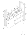
- FIG. 3A is a perspective view showing a state in which the first chuck of one first transfer section and the second chuck of the other first transfer section are positioned above the first tank and the second tank, respectively.
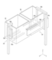
- FIG. 3B is a perspective view showing a state in which the first chuck of one first transfer section and the second chuck of the other first transfer section are positioned inside the first tank and the second tank, respectively.
- FIG. 3C is a perspective view showing a state in which both the first chuck of one first transfer section and the second chuck of the other first transfer section are positioned above the first tank.
- FIG. 4A is a side view showing a state in which the first chuck of one first transfer section and the second chuck of the other first transfer section are positioned above the first tank and the second tank, respectively.
- FIG. 4B is a side view showing a state in which the first chuck of one first transfer section and the second chuck of the other first transfer section are positioned inside the first tank and the second tank, respectively.
- FIG. 4C is a side view showing a state in which both the first chuck of one first transfer section and the second chuck of the other first transfer section are positioned above the first tank.
- 3A and 4A correspond
- FIGS. 3B and 4B correspond
- FIGS. 3C and 4C correspond.
- the other first transfer section 34 includes a second chuck 34a for holding a plurality of substrates W and a second chuck 34a. , an actuator 34c that raises and lowers the arm 34b in the Z-axis direction (third direction), and an actuator 34d that moves the actuator 34c in the X-axis direction (first direction).
- the second chuck 34a can be raised and lowered by the actuator 34c. Thereby, the second chuck 34a can be positioned within the second tub 30 as shown in FIGS. 3B and 4B.
- the actuator 34d also allows the second chuck 34a to move between a position above the second tank 30 and a position above the first tank 32, as shown in FIGS. 3A, 3C, 4A, and 4C. is.
- the first transport unit 36 includes a first chuck 36a that holds a plurality of substrates W, an arm 36b that supports the first chuck 36a, and the arm 36b that extends in the Z-axis direction (third direction) and an actuator 36c that moves up and down.
- the first chuck 36a can be raised and lowered by the actuator 36c. Thereby, the first chuck 36a can be positioned within the first tub 32, as shown in FIGS. 3B and 4B. In addition, in the case of the first embodiment, unlike the second chuck 34a, the first chuck 36a does not move in the X-axis direction (first direction).
- the actuator 34c and the actuator 34d of the first conveying unit 34 are positioned on one side (the right side in the case of the first embodiment) in the Y-axis direction (second direction) with respect to the second tank 30. are placed in The actuator 36c of the first transfer section 36 is positioned on one side of the first tank 32 in the X-axis direction (first direction), that is, in front of the first tank 32 (opposite side of the second tank 30 across the first tank 32) side).
- the second chuck 34a of the first transport unit 34 and the first chuck 36a of the first transport unit 36 correspond to each other so that the substrates W can be transferred to each other.
- the second chuck 34a and the first chuck 36a are comb-shaped chucks when viewed from above (as viewed in the Z-axis direction).
- the second chuck 34a includes a main body portion 34e connected to an arm 34b, and a main body portion 34e extending forward in the X-axis direction (first direction), and a plurality of substrates W are placed thereon. and a plurality of support rods 34f.
- the first chuck 36a includes a body portion 36d connected to the arm 36b, and a plurality of support rods 36e extending rearward in the X-axis direction from the body portion 36d and on which a plurality of substrates W are placed.
- Each of the support rods 34f and 36e is formed with a plurality of grooves (not shown) that engage with the outer peripheral edges of the plurality of substrates W to maintain the plurality of substrates W at a predetermined interval. .
- the plurality of substrates W are held by the first and second chucks 36a and 34a while being spaced apart in the X-axis direction.
- the second chuck 34a and the first chuck 36a each include four support rods 34f and 36e.
- the number of support rods on which the substrate W is placed may be three or more, and may differ between the second chuck 34a and the first chuck 36a.
- the second chuck 34a and the first chuck 36a are configured such that the plurality of support rods 34f and 36e can pass through each other in the Z-axis direction (third direction). .
- FIG. 5 is a top view showing a state in which both the first chuck of one first transfer section and the second chuck of the other first transfer section are positioned above the first tank.
- FIG. 6 is a diagram showing transfer of the substrate between the first chuck and the second chuck.
- transfer of a plurality of substrates W between the second chuck 34a and the first chuck 36a is performed above the first tank 32.
- the plurality of support rods 34f of the second chuck 34a and the plurality of support rods 36e of the first chuck 36a are positioned between the body portion 34e of the second chuck 34a and the body portion 36d of the first chuck 36a.
- the plurality of support rods 34f of the second chuck 34a and the plurality of support rods 36e of the first chuck 36a can contact the plurality of substrates W at the same time.
- the support rod 34f of the second chuck 34a and the plurality of support rods 36e of the first chuck 36a are positioned at the Z positions of the first and second chucks 36a and 34a. There is no overlap in the axial direction (third direction).
- the first and second chucks 36a, 34a can pass in the Z direction relative to each other without their support rods contacting each other.
- the plurality of substrates W remain on the plurality of support rods 36e of the first chuck 36a, and the plurality of substrates W are transferred to the first chuck 36a.
- a plurality of substrates W are supplied from the loading module 12 to the second chuck 34a of the first transport section 34 by the second transport section 20, and then transferred from the second chuck 34a to the first transport section. It is delivered to the first chuck 36 a of the section 36 . Then, the plurality of substrates W on the first chuck 36 a are collected by the second transport section 20 and transported to the drying module 16 .
- the supply of the substrate W to the second chuck 34a of the first transport unit 34 and the recovery of the substrate W from the first chuck 36a of the first transport unit 36 are performed by the common second transport unit. 20.
- FIG. 7 is a perspective view of the second transfer section holding the substrate in the substrate processing apparatus according to Embodiment 1.
- FIG. 8 is a perspective view showing a chuck in the second transport section.
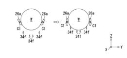
- FIG. 9 is a diagram showing the holding and releasing of the substrate on the chuck.
- the moving head 24 of the actuator 25 of the second transfer section 20 is arranged in front and above the substrate processing apparatus 10 (that is, modules 12 to 18). It moves on rails 22 extending in the Y-axis direction (second direction).
- the actuator 25 is arranged on the side of the first tank 32 in the X-axis direction (first direction).
- the actuator 25 is positioned above the first tank 32 . Therefore, the moving head 24 of the actuator 25 moves above the first tank 32 in the Y-axis direction.
- the actuator 25 of the second transfer section 20 moves from the processing space S1 in which the first tank 32 and the second tank 34 are arranged. It is arranged in an isolated drive space S2.
- the driving space S2 is provided above the processing space S1.
- the actuator 25 is laid on the inner top plate portion 14a of the chemical module 14 separating the processing space S1 and the driving space S2. That is, the inner top plate portion 14 a exists between the first tank 32 and the moving head 24 that moves on the rails 22 of the actuator 25 .
- the inner top plate portion 14 a prevents foreign matter generated by the movement of the moving head 24 on the rail 22 from falling into the first tank 32 .
- the chemical module 14 has the inner top plate portion 14a and the outer top plate portion 14b arranged thereabove.
- the actuator 25 is arranged in a drive space S2 formed between the inner top plate portion 14a and the outer top plate portion 14b.
- the chuck 26 in the second transfer section 20 rotates around the rotation center line C1 extending in the X-axis direction (first direction) of the substrate processing apparatus 10. It has a pair of rotating chuck claws 26a.
- the chuck claws 26 a are arranged to face each other in the Y-axis direction (second direction) of the substrate processing apparatus 10 .
- the chuck claws 26a of the chuck 26 have a non-circular shape when viewed in the direction in which the rotation center line C1 extends (that is, when viewed in the X-axis direction (first direction)). In the case of , it is an oval shape. In the case of the first embodiment, the rotation center line C1 passes through the shape center of the chuck claw 26a when viewed from the first direction. Note that the rotation center line C1 may deviate from the shape center as long as the chuck claws 26a can hold a plurality of substrates W.
- the shape of the chuck claws 26a is not particularly limited as long as the function of the chuck 26 is not impaired, and may be, for example, an elliptical shape, a rectangular shape, a triangular shape, or the like.
- Each chuck claw 26a has a first support surface 26b and a second support surface 26c that support the outer peripheral edges of the plurality of substrates W. As shown in FIG.
- the chuck 26 holds or releases the substrate W by rotating each of the pair of chuck claws 26a.
- the holding posture (posture indicated by the solid line) is such that the shortest distance D1 between the pair of chuck claws 26a is smaller than the size w1 of the substrate W in the Y-axis direction (second direction) of the substrate processing apparatus 10. are held by the pair of chuck claws 26a, the chuck 26 can hold the substrate W.
- the chuck 26 releases the substrate W when each of the pair of chuck claws 26a assumes a release posture (posture indicated by a broken line) in which the shortest distance D1 is larger than the size w1 of the substrate W in the Y-axis direction. be able to.
- the substrate W can pass in the Z-axis direction (third direction) of the substrate processing apparatus 10 between the pair of chuck claws 26a.
- the first and second support surfaces 26b and 26c of the pair of chuck claws 26a are engaged with the outer peripheral edges of the plurality of substrates W to maintain the plurality of substrates W at a predetermined interval.
- a plurality of grooves (not shown) are formed.
- the chuck 26 is arranged above the first tank 32 .
- the chuck 26 passes above the first tank 32 in the Y-axis direction).
- the second transport section 20 has an arm 28 that connects the moving head 24 and the chuck 26 .
- the moving head 24 is arranged above the chuck 26 as shown in FIGS. 4A to 4C. Therefore, the arm 28 connecting these extends in the height direction (Z-axis direction) of the substrate processing apparatus 10 and supports the chuck 26 at its lower end.
- the arm 28 extending in the height direction in this way is less likely to bend than the arm extending in the X-axis direction (first direction).
- the arm 28 will have at least a portion extending in the X-axis direction (first direction).
- the portion of the arm 28 extending in the first direction in this way is likely to be greatly bent by its own weight and the weight of the chuck 26 .
- the inertia of the chuck 26 tends to cause the arm 28 to bend greatly.
- the arm 28 extends at a position deviated from above the first tank 32 .
- the arm 28 does not extend.
- the arm 28 does not pass above the first tank 32 .
- foreign matter adhering to the arm 28 is prevented from falling into the first tank 32 .
- the chemical module 14 has a hanging plate that separates the arm 28 from the space S3 above the first tank 32 when viewed in the Y-axis direction (second direction). 14c.
- the hanging plate 14c extends in the Z-axis direction (third direction) from the inner top plate portion 14a. This hanging plate 14 c suppresses movement of foreign matter adhering to the arm 28 toward the first tank 32 .
- the chemical module 14 has the outer wall portion 14d disposed on the outer side of the hanging plate 14c. Arm 28 moves between flap 14c and outer wall 14d.
- the chuck 26 of the second transport section 20 passes above the first tank 32 in the Y-axis direction (second direction). Therefore, the transfer of the substrate W from the chuck 26 to the second chuck 34 a of the first transfer unit 34 (that is, the supply of the substrate W) is performed above the first tank 32 .
- FIG. 10 is a diagram showing transfer of the substrate from the chuck of the second transfer section to the second chuck of the other first transfer section.
- the chuck 26 of the second transfer section 20 that has received the plurality of substrates W in the loading module 12 arrives above the first tank 32 of the chemical module 14 .
- a plurality of support rods 34f of the second chuck 34a of the first transfer section 34 are arranged below the chuck 26.
- the second chuck 34 a rises, and the plurality of support rods 34 f come into contact with the outer peripheral edges of the plurality of substrates W held by the chuck 26 .
- the pair of chuck claws 26a of the chuck 26 rotates and the plurality of substrates W are released.
- the second chuck 34 a that has received the substrate W moves upward in the X-axis direction (first direction) of the second tank 30 and then moves into the second tank 30 .
- the chuck 26 becomes movable in the Y-axis direction (second direction).
- the transfer of the substrate W from the first chuck 36 a of the first transfer unit 36 to the chuck 26 (that is, collection of the substrate W) is also performed above the first tank 32 .
- FIG. 11 is a diagram showing transfer of a substrate from the first chuck of one of the first transfer units to the chuck of the second transfer unit.
- the chuck 26 of the second transfer section 20 arrives above the first tank 32 of the chemical module 14 .
- the pair of chuck claws 26a of the chuck 26 takes a release posture that allows the substrate W to pass therebetween in the Z-axis direction (third direction).
- the first chuck 36a of the first transfer section 36 moves upward from the inside of the first tank 32 while holding the plurality of substrates W.
- the pair of chuck claws 26a rotates to change from the release posture to the holding posture. This completes the transfer of the substrate W to the pair of chuck claws 26a.
- the first chuck 36a descends and moves into the first tank 32.
- the chuck 26 becomes movable in the Y-axis direction (second direction).
- the chuck 26 of the second transport section 20 transports the substrate W from the loading module 12 to the second chuck 34a of the first transport section 34 of the chemical module 14.
- the substrate W is transferred from the first chuck 36 a of the first transfer section 36 to the drying module 16 . That is, the chuck 26 conveys the substrate W in a dry state before processing, and also conveys the substrate W after processing that is wet with the cleaning liquid in the first tank 32 . Therefore, the pair of chuck claws 26a of the chuck 26 has a first support surface 26b for supporting the dry substrate W and a second support surface 26c for supporting the wet substrate W, as shown in FIG. Prepare.
- the center of rotation of the chuck claws 26a is placed between the first support surface 26b and the second support surface 26c.
- a groove 26d extending in the X-axis direction (first direction) along which the line C1 extends is formed.
- a nozzle (not shown) for sucking and recovering the cleaning liquid accumulated in the groove 26d may be provided on the chuck claw 26a.
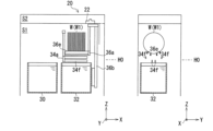
- 12A to 12J show a plurality of operations in an example substrate processing performed by the substrate processing apparatus.
- 12A to 12J each show a side view (left view) and a front view (right view) of the chemical module.
- the second chuck 34a of the first conveying unit 34 is on standby above the first tank 32 at the reference height H0 (initial position). Also, the first chuck 36 a of the first transfer section 36 is on standby in the first tank 32 . In this state, the chuck 26 of the second transport section 20 transports a plurality of substrates W (preceding substrate W1) to be processed to a position above the first tank 32 at a level higher than the reference height H0.
- the second chuck 34a of the first transfer section 34 is lifted, whereby the plurality of substrates held by the chucks 26 of the second transfer section 20 via the first support surfaces 26b are lifted.
- W previously substrate W1
- the plurality of support rods 34f come into contact with the outer peripheral edge of the substrate W (previous substrate W1) positioned between the chuck claws 26a of the chuck 26.
- the chuck 26 of the second transfer section 20 releases the plurality of substrates W.
- FIG. 12B the second chuck 34a of the first transfer section 34 is lifted, whereby the plurality of substrates held by the chucks 26 of the second transfer section 20 via the first support surfaces 26b are lifted.
- W previously substrate W1
- the plurality of support rods 34f come into contact with the outer peripheral edge of the substrate W (previous substrate W1) positioned between the chuck claws 26a of the chuck 26.
- the second chuck 34a of the first transfer section 34 on which the plurality of substrates W (preceding substrate W1) are placed moves upward in the second tank 30 in the X-axis direction (second 1 direction), and descends into the second tank 30 after the movement.
- the plurality of substrates W (preceding substrate W1) are immersed in the chemical solution in the second tank 30 and treated with the chemical solution.
- the second transfer section 20 moves to the loading module 12 to receive the substrate to be processed next (subsequent substrate).
- the second chuck 34a is lifted upward from the second tank 30, and after that, the first tank 32 in the X-axis direction (first direction).
- the second chuck 34 a of the first transport section 34 holding the plurality of substrates W (previous substrate W ⁇ b>1 ) processed with the chemical solution is arranged above the first chuck 36 a of the first transport section 36 .
- the first chuck 36a of the first transfer unit 36 is lifted, whereby the plurality of substrates W ( A preceding substrate W1) is placed on a plurality of support rods 36e of the first chuck 36a.
- the second chuck 34a descends to the initial position at the reference height H0, the transfer of the substrate W (previous substrate W1) from the second chuck 34a to the first chuck 36a is completed.
- the second chuck 34a moves above the second tank 30.
- the first chuck 36 a holding the plurality of substrates W can be lowered into the first tank 32 .
- the plurality of substrates W are immersed in the cleaning liquid in the first bath 32 and cleaned.
- the second chuck 34a moves above the first tank 32, as shown in FIG. 12G.
- a second transfer section holding a plurality of substrates W newly received by the loading module 12 (substrates W2 subsequent to the preceding substrate W1) above the second chuck 34a via a first support surface 26b. Twenty chucks 26 are arranged.
- the second chuck 34a is lifted, and the plurality of substrates W (subsequent substrates W2) held by the chucks 26 of the second transfer section 20 via the first support surfaces 26b are moved to the second position. It rests on a plurality of support rods 34f of chuck 34a.
- the chuck 26 of the second transfer section 20 releases the plurality of substrates W.
- the second chuck 34a of the first transfer unit 34 holding a plurality of substrates W moves upward in the second tank 30 in the X-axis direction (second 1 direction), and descends into the second tank 30 after the movement.
- the plurality of substrates W are immersed in the chemical solution in the second tank 30 and treated with the chemical solution.
- the plurality of substrates W preceding substrate W1 were cleaned in the first bath 32, and the plurality of substrates W (subsequent substrate W2) were chemically treated in the second bath 30. become a state.
- the first chuck 36a is lifted as shown in FIG. 12J.
- the chuck 26 of the second transfer unit 20 holds the plurality of substrates W (preceding substrate W1) placed on the plurality of support rods 36e of the first chuck 36a that has been raised, via the second support surface 26c.
- the first support surface 26b is kept from getting wet.
- the first chuck 36 a retreats into the first tank 32 , and the second transport section 20 transports the substrate W (previous substrate W ⁇ b>1 ) to the drying module 16 .
- the operation of the first and second baths 32 and 30 is By increasing the rate, the throughput of the substrate processing apparatus 10 can be improved.
- the first and second tanks 32 and 30 are kept in a state in which the substrates W are present in the first and second tanks 32 and 30 by the two first transport parts 34 and 36, and the first and second tanks 32, 30 operating rate is improved.
- the operating rate of the first and second tanks 32, 30 is improved.
- the throughput of the substrate processing apparatus 10 is improved.
- Embodiment 2 differs from Embodiment 1 described above in that the first conveying section and the second conveying section are different. Therefore, the second embodiment will be described, focusing on the differences from the first embodiment.
- symbol is attached
- FIG. 13 is a perspective view of a substrate processing apparatus according to Embodiment 2.
- FIG. 14 is a side view of a chemical module in the substrate processing apparatus according to the second embodiment.
- FIG. 15 is a perspective view of the second transport section in the substrate processing apparatus according to the second embodiment.
- FIG. 16 is a perspective view showing a plurality of first transfer parts in the substrate processing apparatus according to the second embodiment.
- the actuator 25 of the second transfer section 120 moves the second tank in the X-axis direction (first direction) of the substrate processing apparatus 110. 30 side. Also, the actuator 25 of the second transfer section 120 is arranged in the upper part of the substrate processing apparatus 110 .
- one first transport section 136 is different from the first transport section 36 according to the first embodiment. different.
- the first chuck 36a of the first transfer section 136 according to the second embodiment is substantially the same as the first chuck 36a of the above-described first embodiment.
- the positions of the arm 136b that supports the first chuck 36a of the first transfer section 136 and the actuator 136c that raises and lowers the arm 136b are different.
- the arm portion 136b and the actuator 136c are not positioned in front of the first tank 32, but in the Y-axis direction ( second direction). As a result, the size of the substrate processing apparatus in the X-axis direction (first direction) is reduced, and the size of the substrate processing apparatus can be reduced.
- the chucks 126 of the second conveying unit 120 extend forward in the X-axis direction (first direction) from the moving head 24 and are parallel to each other. , two support bars 126b extending in the X-axis direction on which a plurality of substrates W are placed, and a plurality of links 126c connecting the rotation shafts 126a and the support bars 126b. It consists of Specifically, each of the support bars 126b is suspended and supported by the corresponding rotating shaft 126a via two one-links 26c.
- each rotating shaft 126a is rotated in the first direction by a motor (not shown) mounted on the moving head 24 of the actuator 25 so that the distance D2 between the two support bars 126b can be varied. Rotated around C2.
- the chuck 126 can hold the substrate W or release the substrate W by changing the distance D2.
- the support bar 126b is formed with a plurality of grooves (not shown) that engage with the outer peripheral edges of the plurality of substrates W to maintain the plurality of substrates W at predetermined intervals.
- the chuck 126 of the second transfer section 120 moves above the first tank 32 in the Y-axis direction (second direction). That is, above the first tank 32, the chuck 126 of the second transport unit 120 supplies the substrate W to the second chuck 34a of the first transport unit 34 and the substrate W from the first chuck 136a of the first transport unit 136. and recovering the substrate W.
- Embodiment 3 differs from Embodiment 1 described above in that the second conveying section is different.
- the substrate processing apparatus 10 has one second transport section 20 as shown in FIG. Therefore, in the chemical module 14, the supply of the substrate W to the second chuck 34a of the first transport unit 34 and the recovery of the substrate W from the first chuck 36a of the first transport unit 36 are performed by this one second transport unit. 20.
- the substrate processing apparatus according to the third embodiment includes a second transport unit that supplies the substrate W to the second chuck 34a of the first transport unit 34, and a first transport unit 36 that supplies the substrate W to the second chuck 34a. It has a separate second transport that performs the collection of substrates W from 36a.
- the third embodiment will be described with a focus on this point of difference.
- symbol is attached
- FIG. 17 is a perspective view of a plurality of second transfer units in the substrate processing apparatus according to Embodiment 3.
- FIG. 18A and 18B are side and top views showing the supply of a plurality of substrates from one second transfer section to the second chuck of the other first transfer section.
- 19A and 19B are a side view and a top view showing recovery of a plurality of substrates from the first chuck of one first transport section to the other second transport section.
- the substrate processing apparatus has two second transport parts 50 and 52 as the second transport parts.
- the second transport section 50 supplies a plurality of substrates W to the second chuck 34a of the first transport section 34, but recovers a plurality of substrates W held by the first chuck 36a of the first transport section 36. do not.
- the other second transport unit 52 collects a plurality of substrates W held by the first chuck 36a of the first transport unit 36, and collects a plurality of substrates W with respect to the second chuck 34a of the first transport unit 34. No substrate W is supplied.
- the two second transport units 50 and 52 hold a plurality of substrates W in a manner different from that of the second transport unit 20 of the first embodiment described above.
- the second transport units 50 and 52 include moving heads 50a and 52a of actuators that move in the Y-axis direction (second direction), and moving heads 50a and 52a in the X-axis direction (first direction) of the substrate processing apparatus 10. and a plurality of support rods 50b, 52b extending on which a plurality of substrates W are placed.
- the illustration of rails of actuators on which the moving heads 50a and 50b move is omitted.
- the moving head 50a of the second conveying section 50 is positioned in front of the first tank 32 when viewed from above (as viewed in the Z-axis direction).
- a plurality of support rods 50b extend upward from the moving head 50a toward the second tank 30.
- the plurality of support rods 50b are arranged in a top view so that the plurality of support rods 34f of the second chuck 34a of the first conveying unit 34 can pass through the plurality of support rods 50b in the Z-axis direction (third direction). support rod 34f.
- the supply of the plurality of substrates W from the second transfer section 50 to the second chuck 34a of the first transfer section 34 is performed above the second tank 30. .
- the second chuck 34a is raised. The lifting causes the plurality of support rods 34f of the second chuck 34a to pass between the plurality of support rods 50b, thereby placing the plurality of substrates W on the plurality of support rods 34f.
- the second chuck 34 a holding the plurality of substrates W can be lowered toward the inside of the second bath 30 .
- the first chuck 36a of the first transport unit 36 is positioned in the first tank 32, and the support rods of the second transport unit 50 are positioned inside the first tank 32. Avoid contact with 50b.
- the moving head 52a of the second conveying section 52 is positioned behind the second tank 32 when viewed from above (as viewed in the Z-axis direction).
- a plurality of support rods 52b extend upward from the moving head 52a.
- the plurality of support rods 52b are arranged so that the plurality of support rods 36e of the first chuck 36a of the first transfer unit 36 can pass between the plurality of support rods 52b in the Z-axis direction (third direction). , does not overlap the plurality of support rods 36e.
- the recovery of the plurality of substrates W from the first chuck 36 a of the first transfer section 36 to the second transfer section 52 is performed above the first tank 32 .
- the first chuck 36a After the first chuck 36a that holds the plurality of substrates W is arranged above the second transfer unit 52, the first chuck 36a is lowered. The descent causes the plurality of support rods 36e of the first chuck 36a to pass between the plurality of support rods 52b, thereby placing the plurality of substrates W on the plurality of support rods 52b.
- the second chuck 34a of the first transfer unit 34 is positioned inside the second tank 30, and the second transfer unit 52 contact with the support rod 52b.
- the second transfer units 50 and 52 move in the Y-axis direction (second direction) of the substrate processing apparatus 10 at different height levels. That is, the second transport parts 50 and 52 are spaced apart from each other in the Z-axis direction (third direction) so that they do not interfere with each other even when they move while holding a plurality of substrates W.
- the first and second The throughput of the substrate processing apparatus can be improved by increasing the operating rate of each of the baths 32 and 30 .
- the third embodiment can is useful.
- the second tank 30 located on the rear side of the substrate processing apparatus 10 is a chemical liquid tank
- the first tank 32 located on the front side of the substrate processing apparatus 10 is a cleaning tank.
- the second tank 30 may be used as a cleaning tank
- the first tank 32 may be used as a chemical tank.
- the second chuck 34a and the first chuck 36a of Embodiment 1 described above are configured to be able to transfer the substrate W to each other, the transfer from the first chuck 36a of the first transfer unit 36 to the first transfer unit 34 is performed. A plurality of substrates W are transferred to the second chuck 34a.
- the second conveying unit 20 is movable in the Y-axis direction (second direction), but does not move in the Z-axis direction (third direction).
- embodiments of the present invention are not limited to this. If the second transport section of the substrate processing apparatus according to the embodiment of the present invention can supply and retrieve a plurality of substrates W to and from the first chuck of the first transport section and the second chuck of the second lifter, , regardless of its form.
- the second chuck 34a of the other first transport unit 34 is movable between a position above the second tank 30 and a position above the first tank 32, and It is possible to go up and down.
- the first chuck 36a of one of the first transfer sections 36 does not move between the upper position of the second tank 30 and the upper position of the first tank 32, but only moves up and down.
- embodiments of the present invention are not limited to this.
- the first chuck of one of the first transfer units may also move between the position above the first tank and the position above the second tank. This improves the degree of freedom in setting the transfer position of the substrate from the second chuck to the first chuck and the recovery position of the substrate from the first chuck to the second transfer section.
- the supply position of the substrates W to and the recovery position of the substrates W from the first chuck 36 a to the second transfer unit 20 are set above the first tank 32 .
- the second chuck 34a of the first conveying unit 34 and the first chuck 36a of the first conveying unit 36 are arranged from above (in the Z-axis direction). (view) is a comb-like chuck.
- embodiments of the present invention are not limited to this.
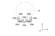
- FIG. 20 is a perspective view of a first chuck of one first transfer section and a second chuck of the other first transfer section in a substrate processing apparatus according to another embodiment.
- FIG. 21 is a diagram showing transfer of a substrate between the first chuck of one first transfer section and the second chuck of the other first transfer section.
- a second chuck 234a of a first transfer section 234 includes a body portion 234b and a body portion 234b extending from the body portion 234b in the X-axis direction (first direction). ), and a plurality of ridges 234d projecting in the Z-axis direction (third direction) from the cantilever portion 234c and extending in the X-axis direction.
- the first chuck 236a of the first transfer section 236 includes a body portion 236b, two plate-shaped cantilever portions 236c extending rearward in the X-axis direction from the body portion 236b, and two cantilever portions.
- a plurality of protrusions 236d extending in the X-axis direction while protruding in the Z-axis direction from each ridge 236c.
- a plurality of substrates W are placed on the plurality of ridges 234d of the second chuck 234a and the plurality of ridges 236d of the first chuck 236a.
- the second chuck 234a moves in the X-axis direction (first direction) toward the first chuck 236a. Due to this movement, as shown in FIG. 13, the two cantilever beams 236c of the first chuck 236a enter the gaps between the plurality of substrates W and the cantilever beams 234c of the second chuck 234a.
- the first chuck 236a rises after entering, the plurality of substrates W are placed on the plurality of ridges 236d of the first chuck 236a.
- first and second chucks 236a, 234a shown in FIGS. 20 and 21 unlike the first and second chucks 36a, 34a of the above-described first embodiment, they are cannot pass through. However, similar to the first and second chucks 36a, 34a of the first embodiment described above, the first and second chucks 236a, 234a are capable of transferring substrates W relative to each other.
- a substrate processing module includes first and second tanks arranged in a first direction in which substrates can be placed, and two first tanks for transporting the substrates. and a transport unit, wherein one of the first transport units includes a first chuck that can move up and down and is arranged in the first tank while holding the substrate, and the other of the first transport units.
- the first chuck and the second chuck are movable between an upper position of the second tank and a substrate can be transferred between the first chuck and the second chuck.
- a substrate processing apparatus includes the substrate processing module described above and another module connected to the substrate processing module in a second direction intersecting the first direction.
- a substrate processing apparatus comprising:
- the present invention is applicable to substrate processing apparatuses that process substrates using a plurality of tanks.
- substrate processing apparatus 10 substrate processing apparatus 14 substrate processing module (chemical module) 30 second tank 32 first tank 34 first transfer section 34a second chuck 36 first transfer section 36a first chuck W substrate
Landscapes
- Chemical & Material Sciences (AREA)
- Chemical Kinetics & Catalysis (AREA)
- General Chemical & Material Sciences (AREA)
- Container, Conveyance, Adherence, Positioning, Of Wafer (AREA)
- Cleaning Or Drying Semiconductors (AREA)
Abstract
Description
第1方向に配列され、基板を配置可能な第1槽および第2槽と、
前記基板を搬送する2つの第1搬送部と、を有し、
一方の前記第1搬送部が、昇降可能であって基板を保持した状態で前記第1槽内に配置される第1チャックを備え、
他方の前記第1搬送部が、昇降可能であって基板を保持した状態で前記第2槽内に配置される第2チャックを備え、
前記第1チャックおよび前記第2チャックの少なくとも一方が、前記第1槽の上方位置と前記第2槽の上方位置との間で移動可能であって、
前記第1チャックおよび前記第2チャックが、両者間で基板を受け渡し可能に構成されている、基板処理モジュールが提供される。
前記基板処理モジュールと、前記基板処理モジュールに対して前記第1の方向に交差する第2の方向に連結される別のモジュールとを備える、基板処理装置が提供される。
図1は、本発明の実施の形態1に係る基板処理装置の斜視図である。なお、図に示すX-Y-Z直交座標系は、発明の理解を容易にするためのものであって、発明を限定するものではない。X軸方向が基板処理装置の前後方向(第1方向)であって、Y軸方向が左右方向(第2方向)であって、Z軸方向が高さ方向(第3方向)である。
本実施の形態2は、第1搬送部および第2搬送部が異なる点で、上述の実施の形態1と異なる。したがって、実施の形態1と異なる点を中心に、本実施の形態2について説明する。なお、上述の実施の形態1の構成要素と実質的に同一の構成要素には、同一の符号を付している。
(実施の形態3)
本実施の形態3は、第2搬送部が異なる点で、上述の実施の形態1と異なる。
14 基板処理モジュール(ケミカルモジュール)
30 第2槽
32 第1槽
34 第1搬送部
34a 第2チャック
36 第1搬送部
36a 第1チャック
W 基板
Claims (9)
- 第1方向に配列され、基板を配置可能な第1槽および第2槽と、
前記基板を搬送する2つの第1搬送部と、を有し、
一方の前記第1搬送部が、昇降可能であって基板を保持した状態で前記第1槽内に配置される第1チャックを備え、
他方の前記第1搬送部が、昇降可能であって基板を保持した状態で前記第2槽内に配置される第2チャックを備え、
前記第1チャックおよび前記第2チャックの少なくとも一方が、前記第1槽の上方位置と前記第2槽の上方位置との間で移動可能であって、
前記第1チャックおよび前記第2チャックが、両者間で基板を受け渡し可能に構成されている、基板処理モジュール。 - 前記第1チャックが、前記基板が載置される櫛歯状のチャックであって、
前記第2チャックが、前記基板が載置される櫛歯状のチャックであって、
前記第1チャックと前記第2チャックが、互いに対して昇降方向に通過可能である、請求項1に記載の基板処理モジュール。 - 前記第1槽が、洗浄槽であって、
前記第2の槽が、薬液槽である、請求項1または2に記載の基板処理モジュール。 - 前記第2チャックが、前記第1槽の上方位置と前記第2槽の上方位置との間で移動可能である、請求項1から3のいずれか一項に記載の基板処理モジュール。
- 前記第1槽の上方位置で、前記第2チャックが保持する前記基板を、前記第1チャックが受け取る、請求項1から4のいずれか一項に記載の基板処理モジュール。
- 前記第1方向と交差する第2方向に前記基板を搬送する第2搬送部を、さらに有する、請求項1から5のいずれか一項に記載の基板処理モジュール。
- 前記第2搬送部が、前記第2チャックに対して前記基板を供給するとともに、前記第1チャックが保持する前記基板を回収する、請求項6に記載の基板処理モジュール。
- 前記第1槽の上方位置で、前記第2搬送部が、前記第2チャックに対して前記基板を供給するとともに、前記第1チャックが支持する前記基板を回収する、請求項7に記載の基板処理モジュール。
- 請求項1から8のいずれか一項に記載の前記基板処理モジュールと、前記基板処理モジュールに対して前記第1方向に交差する第2の方向に連結される別のモジュールとを備える、基板処理装置。
Priority Applications (7)
| Application Number | Priority Date | Filing Date | Title |
|---|---|---|---|
| JP2023570536A JP7814420B2 (ja) | 2021-12-27 | 2021-12-27 | 基板処理モジュールおよびそれを備える基板処理装置 |
| CN202180102330.XA CN117981054A (zh) | 2021-12-27 | 2021-12-27 | 基板处理模块和具备基板处理模块的基板处理装置 |
| PCT/JP2021/048655 WO2023127049A1 (ja) | 2021-12-27 | 2021-12-27 | 基板処理モジュールおよびそれを備える基板処理装置 |
| KR1020247008263A KR102812992B1 (ko) | 2021-12-27 | 2021-12-27 | 기판 처리 모듈 및 그것을 구비하는 기판 처리 장치 |
| US18/693,072 US20240383015A1 (en) | 2021-12-27 | 2021-12-27 | Substrate processing module and substrate processing device provided with same |
| EP21969933.7A EP4459663A4 (en) | 2021-12-27 | 2021-12-27 | SUBSTRATE PROCESSING MODULE AND SUBSTRATE PROCESSING DEVICE EQUIPPED WITH SAME |
| TW111149282A TWI921631B (zh) | 2021-12-27 | 2022-12-21 | 基板處理模組及具備該模組的基板處理裝置 |
Applications Claiming Priority (1)
| Application Number | Priority Date | Filing Date | Title |
|---|---|---|---|
| PCT/JP2021/048655 WO2023127049A1 (ja) | 2021-12-27 | 2021-12-27 | 基板処理モジュールおよびそれを備える基板処理装置 |
Publications (1)
| Publication Number | Publication Date |
|---|---|
| WO2023127049A1 true WO2023127049A1 (ja) | 2023-07-06 |
Family
ID=86998341
Family Applications (1)
| Application Number | Title | Priority Date | Filing Date |
|---|---|---|---|
| PCT/JP2021/048655 Ceased WO2023127049A1 (ja) | 2021-12-27 | 2021-12-27 | 基板処理モジュールおよびそれを備える基板処理装置 |
Country Status (6)
| Country | Link |
|---|---|
| US (1) | US20240383015A1 (ja) |
| EP (1) | EP4459663A4 (ja) |
| JP (1) | JP7814420B2 (ja) |
| KR (1) | KR102812992B1 (ja) |
| CN (1) | CN117981054A (ja) |
| WO (1) | WO2023127049A1 (ja) |
Families Citing this family (1)
| Publication number | Priority date | Publication date | Assignee | Title |
|---|---|---|---|---|
| JP1728449S (ja) * | 2022-03-30 | 2022-10-27 | 基板処理装置 |
Citations (5)
| Publication number | Priority date | Publication date | Assignee | Title |
|---|---|---|---|---|
| JPH11145249A (ja) * | 1997-11-10 | 1999-05-28 | Tokyo Electron Ltd | 基板の整列装置 |
| JP2000306880A (ja) * | 1999-04-20 | 2000-11-02 | Tokyo Electron Ltd | 処理システム |
| JP2018056158A (ja) | 2016-09-26 | 2018-04-05 | 株式会社Screenホールディングス | 基板処理方法及び基板処理装置 |
| JP2021048271A (ja) * | 2019-09-19 | 2021-03-25 | 株式会社ディスコ | 加工装置 |
| JP2021072439A (ja) * | 2019-10-28 | 2021-05-06 | 東京エレクトロン株式会社 | バッチ形成機構および基板処理装置 |
Family Cites Families (6)
| Publication number | Priority date | Publication date | Assignee | Title |
|---|---|---|---|---|
| US5976198A (en) * | 1995-06-09 | 1999-11-02 | Dainippon Screen Mfg. Co., Ltd. | Substrate transfer and bath apparatus |
| KR100483753B1 (ko) * | 1995-07-31 | 2005-04-18 | 동경 엘렉트론 주식회사 | 세정장치 |
| JP2000068364A (ja) * | 1998-08-24 | 2000-03-03 | Seiko Epson Corp | キャリアおよび表面処理方法並びに表面処理装置 |
| JP5004612B2 (ja) * | 2007-02-15 | 2012-08-22 | 大日本スクリーン製造株式会社 | 基板処理装置 |
| JP5274161B2 (ja) * | 2008-09-01 | 2013-08-28 | 株式会社東京精密 | ウェーハ収納リンス装置、ウェーハ収納リンス方法、及びウェーハ研磨装置 |
| JP7336956B2 (ja) * | 2019-10-10 | 2023-09-01 | 東京エレクトロン株式会社 | 基板処理システム、及び基板処理方法 |
-
2021
- 2021-12-27 WO PCT/JP2021/048655 patent/WO2023127049A1/ja not_active Ceased
- 2021-12-27 JP JP2023570536A patent/JP7814420B2/ja active Active
- 2021-12-27 EP EP21969933.7A patent/EP4459663A4/en active Pending
- 2021-12-27 US US18/693,072 patent/US20240383015A1/en active Pending
- 2021-12-27 KR KR1020247008263A patent/KR102812992B1/ko active Active
- 2021-12-27 CN CN202180102330.XA patent/CN117981054A/zh active Pending
Patent Citations (5)
| Publication number | Priority date | Publication date | Assignee | Title |
|---|---|---|---|---|
| JPH11145249A (ja) * | 1997-11-10 | 1999-05-28 | Tokyo Electron Ltd | 基板の整列装置 |
| JP2000306880A (ja) * | 1999-04-20 | 2000-11-02 | Tokyo Electron Ltd | 処理システム |
| JP2018056158A (ja) | 2016-09-26 | 2018-04-05 | 株式会社Screenホールディングス | 基板処理方法及び基板処理装置 |
| JP2021048271A (ja) * | 2019-09-19 | 2021-03-25 | 株式会社ディスコ | 加工装置 |
| JP2021072439A (ja) * | 2019-10-28 | 2021-05-06 | 東京エレクトロン株式会社 | バッチ形成機構および基板処理装置 |
Non-Patent Citations (1)
| Title |
|---|
| See also references of EP4459663A4 |
Also Published As
| Publication number | Publication date |
|---|---|
| EP4459663A1 (en) | 2024-11-06 |
| US20240383015A1 (en) | 2024-11-21 |
| JPWO2023127049A1 (ja) | 2023-07-06 |
| EP4459663A4 (en) | 2025-10-08 |
| CN117981054A (zh) | 2024-05-03 |
| TW202329232A (zh) | 2023-07-16 |
| KR102812992B1 (ko) | 2025-05-27 |
| JP7814420B2 (ja) | 2026-02-16 |
| KR20240122738A (ko) | 2024-08-13 |
Similar Documents
| Publication | Publication Date | Title |
|---|---|---|
| JP3510463B2 (ja) | 基板の整列装置及び整列方法 | |
| KR100989851B1 (ko) | 이송부재의 속도 조절 방법, 이를 이용한 기판 이송 방법 및 기판 처리 장치 | |
| KR100982366B1 (ko) | 기판처리장치 | |
| JP5505384B2 (ja) | 基板処理装置、基板処理方法および記憶媒体 | |
| CN104813438A (zh) | 半导体硅片的清洗方法和装置 | |
| JP2002198414A (ja) | 基板処理装置および基板処理方法 | |
| JP2018098301A (ja) | 基板処理装置 | |
| JP3450138B2 (ja) | 基板処理装置 | |
| KR20200083233A (ko) | 기판 처리 장치 및 기판 반송 방법 | |
| WO2023127049A1 (ja) | 基板処理モジュールおよびそれを備える基板処理装置 | |
| JP7814421B2 (ja) | 基板処理モジュールおよびそれを備える基板処理装置 | |
| JP5059054B2 (ja) | 基板処理システム、基板検出装置および基板検出方法 | |
| JP5875901B2 (ja) | 基板処理装置 | |
| WO2004075285A1 (ja) | 基板処理装置 | |
| TWI604522B (zh) | Semiconductor wafer cleaning method and device | |
| JP2013239645A (ja) | 被処理基板の乾燥装置及び乾燥方法 | |
| TWI921631B (zh) | 基板處理模組及具備該模組的基板處理裝置 | |
| JP3248789B2 (ja) | 基板ウェット処理方法および処理システム | |
| CN116544143A (zh) | 用于晶圆的清洗装置以及半导体设备 | |
| JPH09321118A (ja) | 基板搬送装置 | |
| KR100909988B1 (ko) | 캐리어 이송 장치 및 이를 갖는 기판 세정 시스템 | |
| KR100831263B1 (ko) | 웨이퍼 간격 조절 장치 및 이를 포함하는 기판 세정 장치 | |
| JP5579796B2 (ja) | 基板処理システム、基板検出装置および基板検出方法 | |
| JPH11145260A (ja) | 基板の保持装置 | |
| JPH11220000A (ja) | 基板処理装置 |
Legal Events
| Date | Code | Title | Description |
|---|---|---|---|
| 121 | Ep: the epo has been informed by wipo that ep was designated in this application |
Ref document number: 21969933 Country of ref document: EP Kind code of ref document: A1 |
|
| WWE | Wipo information: entry into national phase |
Ref document number: 2023570536 Country of ref document: JP |
|
| WWE | Wipo information: entry into national phase |
Ref document number: 202180102330.X Country of ref document: CN |
|
| WWE | Wipo information: entry into national phase |
Ref document number: 18693072 Country of ref document: US |
|
| WWE | Wipo information: entry into national phase |
Ref document number: 11202401909P Country of ref document: SG |
|
| NENP | Non-entry into the national phase |
Ref country code: DE |
|
| ENP | Entry into the national phase |
Ref document number: 2021969933 Country of ref document: EP Effective date: 20240729 |