WO2023132143A1 - 超音波発生装置及び超音波発生システム - Google Patents
超音波発生装置及び超音波発生システム Download PDFInfo
- Publication number
- WO2023132143A1 WO2023132143A1 PCT/JP2022/042994 JP2022042994W WO2023132143A1 WO 2023132143 A1 WO2023132143 A1 WO 2023132143A1 JP 2022042994 W JP2022042994 W JP 2022042994W WO 2023132143 A1 WO2023132143 A1 WO 2023132143A1
- Authority
- WO
- WIPO (PCT)
- Prior art keywords
- inner peripheral
- peripheral surface
- ultrasonic
- ultrasonic wave
- waveguide
- Prior art date
- Legal status (The legal status is an assumption and is not a legal conclusion. Google has not performed a legal analysis and makes no representation as to the accuracy of the status listed.)
- Ceased
Links
Images


Classifications
-
- H—ELECTRICITY
- H04—ELECTRIC COMMUNICATION TECHNIQUE
- H04R—LOUDSPEAKERS, MICROPHONES, GRAMOPHONE PICK-UPS OR LIKE ACOUSTIC ELECTROMECHANICAL TRANSDUCERS; ELECTRIC HEARING AIDS; PUBLIC ADDRESS SYSTEMS
- H04R1/00—Details of transducers, loudspeakers or microphones
- H04R1/20—Arrangements for obtaining desired frequency or directional characteristics
- H04R1/32—Arrangements for obtaining desired frequency or directional characteristics for obtaining desired directional characteristic only
- H04R1/34—Arrangements for obtaining desired frequency or directional characteristics for obtaining desired directional characteristic only by using a single transducer with sound reflecting, diffracting, directing or guiding means
-
- B—PERFORMING OPERATIONS; TRANSPORTING
- B06—GENERATING OR TRANSMITTING MECHANICAL VIBRATIONS IN GENERAL
- B06B—METHODS OR APPARATUS FOR GENERATING OR TRANSMITTING MECHANICAL VIBRATIONS OF INFRASONIC, SONIC, OR ULTRASONIC FREQUENCY, e.g. FOR PERFORMING MECHANICAL WORK IN GENERAL
- B06B3/00—Methods or apparatus specially adapted for transmitting mechanical vibrations of infrasonic, sonic, or ultrasonic frequency
-
- G—PHYSICS
- G10—MUSICAL INSTRUMENTS; ACOUSTICS
- G10K—SOUND-PRODUCING DEVICES; METHODS OR DEVICES FOR PROTECTING AGAINST, OR FOR DAMPING, NOISE OR OTHER ACOUSTIC WAVES IN GENERAL; ACOUSTICS NOT OTHERWISE PROVIDED FOR
- G10K11/00—Methods or devices for transmitting, conducting or directing sound in general; Methods or devices for protecting against, or for damping, noise or other acoustic waves in general
- G10K11/18—Methods or devices for transmitting, conducting or directing sound
-
- B—PERFORMING OPERATIONS; TRANSPORTING
- B06—GENERATING OR TRANSMITTING MECHANICAL VIBRATIONS IN GENERAL
- B06B—METHODS OR APPARATUS FOR GENERATING OR TRANSMITTING MECHANICAL VIBRATIONS OF INFRASONIC, SONIC, OR ULTRASONIC FREQUENCY, e.g. FOR PERFORMING MECHANICAL WORK IN GENERAL
- B06B1/00—Methods or apparatus for generating mechanical vibrations of infrasonic, sonic, or ultrasonic frequency
- B06B1/02—Methods or apparatus for generating mechanical vibrations of infrasonic, sonic, or ultrasonic frequency making use of electrical energy
- B06B1/06—Methods or apparatus for generating mechanical vibrations of infrasonic, sonic, or ultrasonic frequency making use of electrical energy operating with piezoelectric effect or with electrostriction
-
- B—PERFORMING OPERATIONS; TRANSPORTING
- B06—GENERATING OR TRANSMITTING MECHANICAL VIBRATIONS IN GENERAL
- B06B—METHODS OR APPARATUS FOR GENERATING OR TRANSMITTING MECHANICAL VIBRATIONS OF INFRASONIC, SONIC, OR ULTRASONIC FREQUENCY, e.g. FOR PERFORMING MECHANICAL WORK IN GENERAL
- B06B3/00—Methods or apparatus specially adapted for transmitting mechanical vibrations of infrasonic, sonic, or ultrasonic frequency
- B06B3/04—Methods or apparatus specially adapted for transmitting mechanical vibrations of infrasonic, sonic, or ultrasonic frequency involving focusing or reflecting
-
- H—ELECTRICITY
- H04—ELECTRIC COMMUNICATION TECHNIQUE
- H04R—LOUDSPEAKERS, MICROPHONES, GRAMOPHONE PICK-UPS OR LIKE ACOUSTIC ELECTROMECHANICAL TRANSDUCERS; ELECTRIC HEARING AIDS; PUBLIC ADDRESS SYSTEMS
- H04R17/00—Piezoelectric transducers; Electrostrictive transducers
-
- G—PHYSICS
- G10—MUSICAL INSTRUMENTS; ACOUSTICS
- G10K—SOUND-PRODUCING DEVICES; METHODS OR DEVICES FOR PROTECTING AGAINST, OR FOR DAMPING, NOISE OR OTHER ACOUSTIC WAVES IN GENERAL; ACOUSTICS NOT OTHERWISE PROVIDED FOR
- G10K11/00—Methods or devices for transmitting, conducting or directing sound in general; Methods or devices for protecting against, or for damping, noise or other acoustic waves in general
- G10K11/18—Methods or devices for transmitting, conducting or directing sound
- G10K11/22—Methods or devices for transmitting, conducting or directing sound for conducting sound through hollow pipes, e.g. speaking tubes
-
- G—PHYSICS
- G10—MUSICAL INSTRUMENTS; ACOUSTICS
- G10K—SOUND-PRODUCING DEVICES; METHODS OR DEVICES FOR PROTECTING AGAINST, OR FOR DAMPING, NOISE OR OTHER ACOUSTIC WAVES IN GENERAL; ACOUSTICS NOT OTHERWISE PROVIDED FOR
- G10K11/00—Methods or devices for transmitting, conducting or directing sound in general; Methods or devices for protecting against, or for damping, noise or other acoustic waves in general
- G10K11/18—Methods or devices for transmitting, conducting or directing sound
- G10K11/26—Sound-focusing or directing, e.g. scanning
- G10K11/28—Sound-focusing or directing, e.g. scanning using reflection, e.g. parabolic reflectors
Definitions
- the present invention relates to an ultrasonic generator and an ultrasonic generation system.
- Non-Patent Document 1 discloses a technique in which a plane wave generated by vibration of piezoelectric ceramics is focused by an ultrasonic focusing unit, propagated to a waveguide with a small diameter, and output from the tip of the waveguide (p7 " 2. Proposed structure” (see Fig. 2(a)).
- Non-Patent Document 1 discloses a configuration in which a through-hole is formed in the ultrasonic wave focusing portion and the waveguide so as to pass through the ultrasonic wave focusing portion and the waveguide (Fig. (b) (c) reference).
- the through-hole can be used, for example, by applying ultrasonic waves to the liquid flowing through the through-hole, sensing the vicinity of the tip of the waveguide through a sensor, and aspirating crushed tissue by ultrasonic waves output from the tip of the waveguide. It is envisioned that it will be used as a route to
- Non-Patent Document 1 is not sufficiently devised for the shape of the through-hole, and there is room for improvement in this respect.
- the purpose of the present invention is to provide a technique that can give a new action to an object in the through-hole by devising the shape of the through-hole penetrating the ultrasonic focusing part and the waveguide.
- An ultrasonic generator of the present invention comprises an ultrasonic wave generating source that generates ultrasonic waves, an ultrasonic wave focusing section that focuses the ultrasonic waves generated from the ultrasonic wave generating source, and an ultrasonic wave focused by the ultrasonic wave focusing section. and a waveguide for transmitting ultrasonic waves.
- the ultrasonic wave generator is arranged in the order of the ultrasonic wave generation source, the ultrasonic wave focusing section, and the waveguide from the rear end side.
- the ultrasonic wave focusing portion and the waveguide have through holes penetrating through the ultrasonic wave focusing portion and the waveguide in the front-rear direction.
- the inner peripheral surface forming the through hole has a first inner peripheral surface and a deformed portion arranged on the distal end side of the first inner peripheral surface.
- the first inner peripheral surface has a shape in which a cross-sectional shape cut in the front-rear direction extends linearly in the front-rear direction.
- the deformable portion is at least one of a portion arranged inside the first inner peripheral surface and a portion arranged outside the first inner peripheral surface in the cross section cut in the longitudinal direction. , are formed over a part or the entire circumference of the inner peripheral surface in the circumferential direction.
- the deformable portion provided on the inner peripheral surface forming the through hole can give a new effect to the object inside the through hole.
- the through-hole may form a channel through which liquid flows.
- the ultrasonic wave focusing portion and the waveguide When the ultrasonic waves transmitted in at least one of the ultrasonic wave focusing portion and the waveguide are applied to the liquid flowing in the through hole via the inner peripheral surface, the ultrasonic wave reaches the vicinity of the inner peripheral surface of the through hole. Liquids tend to be biased.
- the deformed portion can generate turbulence in the flow of the liquid in the through hole, so that the ultrasonic wave entering through the inner peripheral surface of the through hole penetrates the liquid as a whole. easier to reach.
- the inner peripheral surface has a second inner peripheral surface disposed on the distal end side of the deformation portion, and the second inner peripheral surface extends in the front-rear direction.
- a cross-sectional shape cut into two may have a shape extending linearly in the front-rear direction.
- the liquid that has flowed into the through-hole from the rear end side and is turbulent at the deformed portion can be made into a laminar flow on the second inner peripheral surface, or brought close to a laminar flow.
- the deformable portion may be provided at a portion of the through hole that penetrates the waveguide.
- the deformable portion may be provided at a portion of the through hole that penetrates the ultrasonic wave focusing portion.
- the ultrasonic generator it is possible to apply ultrasonic waves having a large amplitude to the liquid flowing through the portion of the through-hole that penetrates the ultrasonic wave focusing portion.
- the present invention by devising the shape of the through-hole passing through the ultrasonic focusing portion and the waveguide, it is possible to give a new action to the object in the through-hole.
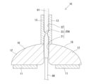
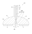
- FIG. 1 is a cross-sectional view of the ultrasonic generator of the first embodiment.
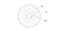
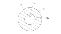
- 2 is a cross-sectional view taken along line XX of FIG. 1.
- FIG. 3 is an explanatory diagram showing a state in which liquid is supplied into the through-hole.
- FIG. 4 is a diagram showing the configuration of an ultrasonic wave generation system.
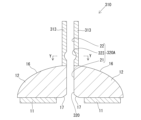
- FIG. 5 is a cross-sectional view of the ultrasonic generator of the second embodiment.
- FIG. 6 is a cross-sectional view of the ultrasonic generator of the third embodiment.
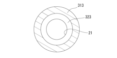
- 7 is a cross-sectional view taken along line YY of FIG. 6.
- FIG. 8 is a cross-sectional view of the ultrasonic generator of the fourth embodiment.
- FIG. 9 is a cross-sectional view of the ultrasonic generator of the fifth embodiment.
- FIG. 10 is a view equivalent to FIG. 2 of an embodiment in which a convex deformed portion is provided only on a part of the inner peripheral surface in the circumferential direction.
- FIG. 11 is a view equivalent to FIG. 7 of an embodiment in which a concave deformed portion is provided only on a part of the inner peripheral surface in the circumferential direction.
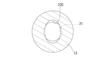
- FIG. 12 is a view equivalent to FIG. 2 of an embodiment in which an elliptical deformed portion is provided.
- FIG. 13 is a view equivalent to FIG. 2 of an embodiment in which a cross-shaped deformed portion is provided.
- FIG. 14 is a view corresponding to FIG. 2 of an embodiment provided with a star-shaped deformed portion.
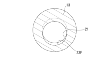
- FIG. 15 is a view equivalent to FIG. 2 of an embodiment in which a deformed portion whose central axis is shifted with respect to the central axis of the first inner peripheral surface is provided.
- FIG. 16 is a cross-sectional view of an ultrasonic generator provided with a plurality of deformable portions.
- FIG. 17 is a cross-sectional view of an ultrasonic generator provided with a second reflecting surface having a form different from that of the first embodiment.
- the ultrasonic generator 10 includes an ultrasonic generator 11 , an ultrasonic focusing unit 12 , and a waveguide 13 .
- the ultrasonic wave generator 11 generates ultrasonic waves.
- the ultrasonic wave focusing unit 12 focuses the ultrasonic waves generated from the ultrasonic wave generation source 11 .
- the waveguide 13 transmits the ultrasonic waves focused by the ultrasonic wave focusing section 12 .
- the ultrasonic wave generator 10 is configured such that an ultrasonic wave generation source 11, an ultrasonic wave focusing section 12, and a waveguide 13 are arranged in this order from the rear end side.
- the ultrasonic wave generator 11 is, for example, a piezoelectric element made of piezoelectric ceramics.
- the ultrasonic wave generating source 11 has a plate shape having a thickness in the front-rear direction.
- the ultrasonic wave generation source 11 has an annular shape (more specifically, an annular shape).
- the ultrasonic wave generation source 11 generates ultrasonic waves upon receiving an electric signal from the power supply device 100, which will be described later.
- the ultrasonic source 11 has a radiation surface 15 for generating ultrasonic waves.
- the radiation surface 15 is provided on the distal end side of the ultrasonic wave generation source 11 and arranged in a state facing forward.
- the radiation surface 15 is a flat surface and extends in a direction orthogonal to the front-rear direction of the ultrasonic generator 10 .
- the ultrasonic waves generated by the ultrasonic wave generating source 11 are plane waves traveling straight ahead.
- the ultrasonic wave generation source 11 generates ultrasonic waves at a frequency of 30 kHz or more and 3 MHz or less, for example.
- the ultrasonic wave focusing part 12 is made of metal (for example, duralumin).
- the ultrasonic wave focusing portion 12 is joined at its rear end to the radiation surface 15 of the ultrasonic wave generating source 11 .
- the ultrasound focusing section 12 has a first reflecting surface 16 and a second reflecting surface 17 .
- the first reflecting surface 16 is arranged to face the radiation surface 15 of the ultrasonic wave generation source 11 .
- the facing direction between the first reflecting surface 16 and the radiation surface 15 of the ultrasonic wave generation source 11 is parallel to the front-rear direction.
- the first reflecting surface 16 is a curved surface (for example, a parabolic surface) that is convex toward the front side (the side opposite to the ultrasonic wave generation source 11) when viewed from the outside of the ultrasonic wave focusing section 12. As shown in FIG. The first reflecting surface 16 has a concave shape when viewed from the inside of the ultrasonic wave focusing section 12 . The central portion of the first reflecting surface 16 is located ahead of the outer peripheral edge of the first reflecting surface 16 . The first reflecting surface 16 is a paraboloid of revolution with the axis A as the axis of rotation. Axis A is an axis line passing through the center of the ultrasonic wave generating source 11 and extending in the front-rear direction. The ultrasonic wave focusing part 12 has an annular shape with the axis A as the central axis.
- the second reflecting surface 17 is arranged to face the first reflecting surface 16 .
- the second reflecting surface 17 is a curved surface (for example, a parabolic surface) convex to the rear side (the side opposite to the first reflecting surface 16) when viewed from the outside of the ultrasonic wave focusing section 12. As shown in FIG.
- the second reflecting surface 17 has a concave shape when viewed from the inside of the ultrasonic wave focusing section 12 .
- the central portion of the second reflecting surface 17 is located ahead of the outer peripheral edge of the second reflecting surface 17 .
- the second reflecting surface 17 has a curved surface shape expanding toward the rear.
- the waveguide 13 has a tubular shape extending forward from the tip of the ultrasonic wave focusing section 12 .
- the waveguide 13 is described as a separate member from the ultrasonic wave focusing section 12 in this embodiment, it may be the same member as the ultrasonic wave focusing section 12 .
- the waveguide 13 is preferably made of a material having high ultrasonic wave propagation properties, such as an aluminum alloy or metallic glass.
- the waveguide 13 may be formed of a shape memory alloy made of an alloy of titanium and nickel, for example.
- the waveguide 13 can be elastically deformed.
- the ultrasonic wave focusing part 12 and the waveguide 13 have a through hole 20 penetrating through the ultrasonic wave focusing part 12 and the waveguide 13 in the front-rear direction.
- the through-hole 20 is formed by the space inside the annular ultrasonic wave focusing portion 12 and the space inside the tubular waveguide 13 .
- the rear end of the inner peripheral surface 20A forming the through hole 20 continues to the front end of the second reflecting surface 17 described above.
- the ultrasonic wave generation source 11 is arranged so as not to block the through hole 20 .
- the ultrasonic wave generation source 11 is arranged outside the outer peripheral edge of the second reflecting surface 17 in a radial direction orthogonal to the front-rear direction (hereinafter also simply referred to as “radial direction”).
- the ultrasonic wave generation source 11 has an annular shape (more specifically, an annular shape) surrounding the outer peripheral edge of the second reflecting surface 17 .
- the through-hole 20 is open to the rear of the ultrasonic wave source 11 via a space inside the ultrasonic wave source 11 .
- the inner peripheral surface 20A forming the through hole 20 has a first inner peripheral surface 21, a second inner peripheral surface 22, and a deformation portion 23.
- the first inner peripheral surface 21 is arranged ahead of the second reflecting surface 17 .
- the rear end of the first inner peripheral surface 21 continues to the front end of the second reflecting surface 17 .
- the first inner peripheral surface 21 has a cross-sectional shape cut in the front-rear direction that extends linearly in the front-rear direction.
- the first inner peripheral surface 21 has a shape obtained by linearly extending a predetermined first cross-sectional shape in the front-rear direction.
- the first cross section is a cross section obtained by cutting the first inner peripheral surface 21 in a direction perpendicular to the front-rear direction.
- the shape and size of the first cross section of the first inner peripheral surface 21 are constant in the front-rear direction.
- the shape of the first cross section of the first inner peripheral surface 21 is circular.
- the second inner peripheral surface 22 is arranged ahead of the first inner peripheral surface 21 .
- the second inner peripheral surface 22 constitutes the tip of the inner peripheral surface 20A.
- the second inner peripheral surface 22 has a cross-sectional shape cut in the front-rear direction that extends linearly in the front-rear direction.
- the second inner peripheral surface 22 has a shape obtained by linearly extending a predetermined second cross-sectional shape in the front-rear direction.
- the second cross section is a cross section obtained by cutting the second inner peripheral surface 22 in a direction perpendicular to the front-rear direction.
- the shape and size of the second cross section of the second inner peripheral surface 22 are constant in the front-rear direction.
- the shape of the second cross section of the second inner peripheral surface 22 is circular.
- the shape and size of the second cross section of the second inner peripheral surface 22 are the same as the shape and size of the first cross section of the first inner peripheral surface 21 . That is, the second cross-sectional shape is the same as the first cross-section
- the deformable portion 23 is provided between the first inner peripheral surface 21 and the second inner peripheral surface 22 in the front-rear direction, and continues to the first inner peripheral surface 21 and the second inner peripheral surface 22 . As shown in FIGS. 1 and 2, the deformed portion 23 is a portion arranged inside the first inner peripheral surface 21 in a cross section cut in the front-rear direction.
- the deformation portion 23 has a shape projecting radially inward from the first inner peripheral surface 21 and the second inner peripheral surface 22 .
- the deformable portion 23 is curved such that the central portion in the front-rear direction protrudes radially inward.
- the deformation portion 23 is formed along the entire circumference of the inner peripheral surface 20A.
- the shape of a cross section obtained by cutting the deformable portion 23 in a direction perpendicular to the front-rear direction is circular.
- the ultrasonic generation system includes an ultrasonic generator 10 and a power supply device 100 as shown in FIG.
- the power supply device 100 outputs electrical signals to the electrodes of the ultrasonic generator 10 to drive the ultrasonic generator 10 .
- the power supply device 100 includes a signal generator 101 , a power amplifier 102 and a measuring instrument 103 .
- a signal generator 101 generates an arbitrary vibration signal.
- the signal generator 101 may use, for example, a frequency response analyzer.
- the power amplifier 102 amplifies the signal output from the signal generator 101 and applies it to the ultrasonic generator 10 .
- a known Power Amplifier may be used for the power amplifier 102.
- a measuring instrument 103 monitors the signal amplified by the power amplifier 102 .
- An oscilloscope for example, may be used as the measuring instrument 103 .
- the power supply device 100 supplies the amplified signal to the ultrasonic generator 10 and monitors the applied voltage.
- the ultrasonic wave focusing unit 12 is made of metal and has electrical conductivity. It is connected to the.
- the power supply device 100 and the ultrasonic wave generating source 11 may be connected directly or via another conductive member.
- the ultrasonic generator 11 When the ultrasonic generator 11 receives an electrical signal from the power supply 100 , it generates ultrasonic waves forward from the radiation surface 15 .
- the ultrasonic waves radiated from the radiation surface 15 are reflected by the first reflecting surface 16 and converge toward the focal point of the first reflecting surface 16 .
- the focal point of the first reflecting surface 16 is the same as the focal point of the second reflecting surface 17 . Therefore, the ultrasonic wave that has passed through the focal point of the first reflecting surface 16 is reflected by the second reflecting surface 17 and introduced into the waveguide 13 as a plane wave.
- the ultrasonic waves introduced into the waveguide 13 are transmitted through the waveguide 13 and radiated from the tip of the waveguide 13 .
- the through-hole 20 penetrating through the ultrasonic focusing part 12 and the waveguide 13 constitutes a channel through which the liquid 91 flows, as shown in FIG. Inside the through hole 20, the liquid 91 supplied from the rear by the liquid supply portion 90 flows forward.
- the liquid 91 flowing through the through hole 20 receives ultrasonic waves transmitted to the ultrasonic wave focusing section 12 and the waveguide 13 by contacting the inner peripheral surface 20A forming the through hole 20 .
- the effect of applying ultrasonic waves to the liquid 91 is to generate microbubbles in the liquid 91, for example.
- the flow of the liquid 91 tends to be laminar. It is difficult for ultrasonic waves to reach liquid 91 on the inner side in the radial direction away from peripheral surface 21 .
- the ultrasonic generator 10 is provided with the deformation portion 23 ahead of the first inner peripheral surface 21 , when the liquid 91 flows from the first inner peripheral surface 21 to the deformation portion 23 , the liquid 91 The flow tends to become turbulent. For this reason, the liquid 91 alternates between the inner side and the outer side in the radial direction, and the ultrasonic waves easily reach the entire liquid 91 .
- the ultrasonic wave generator 10 has a configuration in which the channel inside the deformable portion 23 is narrower than the channel inside the first inner peripheral surface 21, so that the ultrasonic wave easily reaches the entire liquid 91 from this point of view as well. ing.
- the deformation portion 23 is provided at a portion of the through hole 20 that penetrates the waveguide 13 .
- the ultrasonic waves transmitted to the ultrasonic wave focusing part 12 and the waveguide 13 are attenuated as they go forward. Therefore, it is possible to apply an ultrasonic wave with a small amplitude to the liquid 91 flowing inside the deformation portion 23 .
- a second inner peripheral surface 22 is provided ahead of the deformation portion 23 . Therefore, the flow of the liquid 91 that has become turbulent at the deformation portion 23 is returned to a laminar flow or a state close to a laminar flow at the second inner peripheral surface 22 . Then, the liquid 91 returned to a laminar or nearly laminar flow is emitted from the tip of the ultrasonic generator 10 .
- the ultrasonic wave generator of the first embodiment has a configuration in which the deformable portion is provided at a portion of the through hole that penetrates the waveguide, but the present invention is not limited to this configuration.
- the deformable portion is provided in a portion of the through hole that penetrates the ultrasonic focusing portion.
- the same reference numerals are given to the same configurations as in the first embodiment, and detailed description thereof will be omitted.
- the ultrasonic wave generator 210 of the second embodiment includes an ultrasonic wave generation source 11, an ultrasonic wave focusing section 212, and a waveguide 213, as shown in FIG.
- the ultrasonic wave focusing portion 212 and the waveguide 213 have a through hole 220 penetrating through the ultrasonic wave focusing portion 212 and the waveguide 213 in the front-rear direction.
- 220 A of internal peripheral surfaces which form the through-hole 220 have the 1st internal peripheral surface 221, the 2nd internal peripheral surface 222, and the deformation
- the ultrasonic wave focusing section 212 is different from the ultrasonic wave focusing section 12 of the first embodiment in that the deformation section 23 is provided, but is common in other respects.
- the waveguide 213 is different from the waveguide 13 of the first embodiment in that the deformation portion 23 is not provided, but is common in other respects.
- the first inner peripheral surface 221 is different from the first inner peripheral surface 21 of the first embodiment in that the length in the front-rear direction is short, but is common in other respects.
- the second inner peripheral surface 222 is different from the second inner peripheral surface 22 of the first embodiment in that the length in the front-rear direction is long, but is common in other respects.
- the deformable portion 23 is provided at a portion of the through-hole 220 that penetrates the ultrasonic wave focusing portion 212 . Therefore, the ultrasonic wave generator 210 of the second embodiment can apply ultrasonic waves having a large amplitude to the liquid 91 flowing inside the deformable portion 23 .
- the shape of the deformation portion is not limited to the configuration of the first embodiment.
- the third embodiment another example of the deformation portion will be described.
- the same reference numerals are given to the same configurations as in the first embodiment, and detailed description thereof will be omitted.
- An ultrasonic wave generator 310 of the third embodiment includes an ultrasonic wave generation source 11, an ultrasonic wave focusing section 12, and a waveguide 313, as shown in FIG.
- the ultrasonic focusing part 12 and the waveguide 313 have a through hole 320 penetrating through the ultrasonic focusing part 12 and the waveguide 313 in the front-rear direction.
- An inner peripheral surface 320 ⁇ /b>A forming the through hole 320 has a first inner peripheral surface 21 , a second inner peripheral surface 22 and a deformation portion 323 .
- the waveguide 313 is different from the waveguide 13 of the first embodiment in that a deformation section 323 is provided in place of the deformation section 23 of the first embodiment, but other points are common.
- the deformation portion 323 is a portion arranged outside the first inner peripheral surface 21 in a cross section taken in the front-rear direction.
- the deformation portion 323 is configured as a recess formed in the inner peripheral surface 320A.
- the deformation portion 323 has a shape recessed radially outward from the first inner peripheral surface 21 and the second inner peripheral surface 22 .
- the deformable portion 323 is curved such that the center portion in the front-rear direction has a large recess.
- the deformation portion 323 is formed along the entire circumference of the inner peripheral surface 320A.
- the ultrasonic generator 310 of the third embodiment can generate turbulence in the flow of the liquid 91 flowing through the through-hole 320 by the deformable portion 323 .
- An ultrasonic wave generator 410 of the fourth embodiment includes an ultrasonic wave generation source 11, an ultrasonic wave focusing section 12, and a waveguide 413, as shown in FIG.
- the ultrasonic focusing part 12 and the waveguide 413 have a through hole 420 penetrating through the ultrasonic focusing part 12 and the waveguide 413 in the front-rear direction.
- 420 A of inner peripheral surfaces which form the through-hole 420 have the 1st inner peripheral surface 421, the 2nd inner peripheral surface 422, and the deformation
- the first inner peripheral surface 421 is arranged ahead of the second reflecting surface 17 .
- the rear end of the first inner peripheral surface 421 continues to the front end of the second reflecting surface 17 .
- the first inner peripheral surface 421 has a cross-sectional shape cut in the front-rear direction that extends linearly in the front-rear direction.
- the first inner peripheral surface 421 has a shape obtained by linearly extending a predetermined first cross-sectional shape in the front-rear direction.
- the shape and size of the first cross section of the first inner peripheral surface 421 are constant in the front-rear direction.
- the shape of the first cross section of the first inner peripheral surface 421 is circular.
- the second inner peripheral surface 422 is arranged ahead of the first inner peripheral surface 421 .
- the second inner peripheral surface 422 constitutes the tip of the inner peripheral surface 420A.
- the second inner peripheral surface 422 has a cross-sectional shape cut in the front-rear direction that extends linearly in the front-rear direction.
- the second inner peripheral surface 422 has a shape obtained by linearly extending a predetermined second cross-sectional shape in the front-rear direction.
- the shape and size of the second cross section of the second inner peripheral surface 422 are constant in the front-rear direction.
- the second cross-sectional shape of the second inner peripheral surface 422 is circular.
- the size of the second cross section of the second inner peripheral surface 422 is larger than the size of the first cross section of the first inner peripheral surface 421 . That is, in this embodiment, the second cross-sectional shape is larger than the first cross-sectional shape.
- the deformation portion 423 is provided between the first inner peripheral surface 421 and the second inner peripheral surface 422 in the front-rear direction, and continues to the first inner peripheral surface 421 and the second inner peripheral surface 422 .
- the deformed portion 423 has a curved shape that expands in diameter toward the front.
- the ultrasonic generator 410 of the fourth embodiment causes the flow of the liquid 91 flowing through the through-hole 420 to generate turbulence by the deformable portion 423 , and returns the flow to a laminar flow by the second inner peripheral surface 422 . You can get closer to the stream. As a result, the ultrasonic waves transmitted through the waveguide 413 can easily reach the entire liquid 91 flowing through the through hole 420 .
- the sensor probe 80 is inserted from behind into the through hole 220 of the ultrasonic generator 210 .
- a sensor 81 is fixed to the tip of the sensor probe 80 .
- the sensor 81 receives, for example, ultrasonic waves emitted from the waveguide 213 and reflected by an object (not shown).
- the ultrasonic generator 210 shown in FIG. 9 is provided with the deformed portion 23 protruding inward on the inner peripheral surface 220A, so that the portion where the sensor probe 80 comes into contact with the inner peripheral surface 220A can be suppressed as much as possible. As a result, leakage of ultrasonic waves through the sensor probe 80 can be suppressed. Also, when the sensor probe 80 contacts the second reflecting surface 17 , the ultrasonic waves reflected by the first reflecting surface 16 may leak from the sensor probe 80 without being reflected by the second reflecting surface 17 . However, as shown in FIG.
- the deformation portion 23 is provided on the side of the ultrasonic wave focusing portion 212 closer to the second reflecting surface 17 between the ultrasonic wave focusing portion 212 and the waveguide 213 . This configuration can more reliably prevent the sensor probe 80 from contacting the second reflecting surface 17 . In addition, it is preferable that the sensor probe 80 is hard to bend.
- the convex deformation portion 23 is integrated with the cylindrical body forming the waveguide 13, but it may be a separate body.
- the convex deforming portion 23 is integrated with the members forming the ultrasonic wave focusing portions 12 and 212, but they may be separate.
- the convex deformation portion 23 is formed along the entire circumference of the inner peripheral surface 20A forming the through hole 20.
- the deformation shown in FIG. may be configured to be formed only in a part of the inner peripheral surface 20A in the circumferential direction. That is, as shown in FIG. 10, the deformable portion 23A may have a shape protruding radially inward from a part of the inner peripheral surface 20A in the circumferential direction.
- the concave deformed portion 323 is formed along the entire circumference of the inner peripheral surface 320A forming the through hole 320.
- the modified example shown in FIG. Like 23B, the structure formed only in a part of circumferential direction in 320 A of internal peripheral surfaces may be sufficient. That is, as shown in FIG.
- the deformation portion 23B may be recessed radially outward from a part of the inner peripheral surface 20A in the circumferential direction.
- the shape of the cross section of the deformation portion is circular, but it may not be circular.
- the shape of the cross section may be elliptical like a deformation portion 23C shown in FIG.
- the waveguide 13 may be radially compressed to make the whole waveguide elliptical.
- the cross-sectional shape may be cross-shaped.
- the shape of the cross section may be a star shape.
- deformation portions 23C, 23D, and 23E shown in FIGS. 23E may be a portion arranged radially inward of the first inner peripheral surface 21, a portion arranged radially outward of the first inner peripheral surface 21, or both. It may be a part composed of. (5)
- a configuration in which the central axis is shifted from the central axis of the first inner peripheral surface 21 may be employed, as in a deformed portion 23F shown in FIG. (6)
- a plurality of deformation portions 23G, 23H, and 23I may be provided at intervals in the front-rear direction. For example, as shown in FIG.
- the configuration may be such that deformation portions 23G, 23H, and 23I are provided on both the ultrasonic wave focusing portion 612 side and the waveguide 613 side. Further, as shown in FIG. 16, both the convex deforming portion 23G illustrated in the first and second embodiments and the concave deforming portions 23H and 23I illustrated in the third embodiment are provided. There may be. Further, in FIG. 16, the deformable portions 23G, 23H, and 23I are arranged with an interval in the front-rear direction, but may be arranged continuously without an interval. Further, in FIG. 16, the convex deforming portion 23G and the concave deforming portions 23H and 23I are formed steplessly, but they may be formed stepwise.
- the first reflecting surface 16 and the second reflecting surface 17 are paraboloids. Not limited to this, both or one of the first reflecting surface 16 and the second reflecting surface 17 may not be a strict paraboloid, and may have a shape that can be approximately regarded as a paraboloid. In other words, both or one of the first reflecting surface 16 and the second reflecting surface 17 allows the ultrasonic waves generated from the ultrasonic wave generation source 11 to pass through the first reflecting surface 16 and the second reflecting surface 17 to the waveguides 13 and 13 . Any surface that is curved to reach 213, 313, and 413 may be used. The first reflecting surface 16 and the second reflecting surface 17 may be composed of a large number of minute planes.
- the shape of the second reflecting surface 17 is not limited to the shape of the first embodiment shown in FIG.
- the ultrasonic wave generating source 11 is a piezoelectric element made of piezoelectric ceramics.
- the ultrasonic source 11 can use other piezoelectric materials.
- the ultrasonic wave generation source 11 may be, for example, a piezoelectric laminate made of piezoelectric ceramics.
- the ultrasonic generators 10, 210, 310, 410 have the second inner peripheral surfaces 22, 222, 422. However, the second inner peripheral surfaces 22, 222, 422 It may be a configuration that does not have.
Landscapes
- Engineering & Computer Science (AREA)
- Physics & Mathematics (AREA)
- Acoustics & Sound (AREA)
- Mechanical Engineering (AREA)
- Signal Processing (AREA)
- Health & Medical Sciences (AREA)
- Otolaryngology (AREA)
- Multimedia (AREA)
- Transducers For Ultrasonic Waves (AREA)
- Investigating Or Analyzing Materials By The Use Of Ultrasonic Waves (AREA)
- Cleaning By Liquid Or Steam (AREA)
Abstract
Description
1-1.超音波発生装置10の構成
超音波発生装置10は、図1に示すように、超音波発生源11と、超音波集束部12と、導波路13と、を備えている。超音波発生源11は、超音波を発生する。超音波集束部12は、超音波発生源11から発生した超音波を集束する。導波路13は、超音波集束部12によって集束された超音波を伝送する。超音波発生装置10は、後端側から超音波発生源11、超音波集束部12、導波路13の順に配置されて構成されている。
超音波発生システムは、図4に示すように、超音波発生装置10と、電源装置100とを備えている。電源装置100は、超音波発生装置10の電極に電気信号を出力し、超音波発生装置10を駆動させる。
超音波発生源11は、電源装置100から電気信号を与えられると、放射面15から先方に向けて超音波を発生する。放射面15から放射された超音波は、第1反射面16で反射され、第1反射面16の焦点に向かって集束する。第1反射面16の焦点は、第2反射面17の焦点と同じとなっている。このため、第1反射面16の焦点を通過した超音波は、第2反射面17で反射され、平面波として導波路13の内部に導入される。導波路13の内部に導入された超音波は、導波路13の内部を伝送され、導波路13の先端から放射される。
第1実施形態の超音波発生装置は、変形部が貫通孔のうち導波路を貫通する部位に設けられる構成であったが、この構成に限定されない。第2実施形態では、変形部が貫通孔のうち超音波集束部を貫通する部位に設けられる例について説明する。なお、第2実施形態の説明では、第1実施形態と同一の構成については同一の符号を付し、詳しい説明を省略する。
変形部の形状は、第1実施形態の構成に限定されない。第3実施形態では、変形部の別の例について説明する。なお、第3実施形態の説明では、第1実施形態と同一の構成については同一の符号を付し、詳しい説明を省略する。
第4実施形態では、変形部の形状の第3の例について説明する。なお、第4実施形態の説明では、第1実施形態と同一の構成については同一の符号を付し、詳しい説明を省略する。
第1実施形態から第4実施形態では、貫通孔を液体が流れる流路として利用する方法について説明したが、別の利用方法を採用してもよい。第5実施形態では、第2実施形態で説明した超音波発生装置を用いて、別の利用方法の一例を説明する。
本発明は上記記述及び図面によって説明した実施形態に限定されるものではなく、例えば次のような実施形態も本発明の技術的範囲に含まれる。また、上述した実施形態や後述する実施形態の様々な特徴は、矛盾しない組み合わせであればどのように組み合わされてもよい。
(1)上記第1実施形態では、凸状の変形部23が導波路13を構成する筒体と一体であったが、別体であってもよい。上記第2実施形態及び第5実施形態では、凸状の変形部23が超音波集束部12,212を構成する部材と一体であったが別体であってもよい。
(2)上記第1実施形態では、凸状の変形部23が貫通孔20を形成する内周面20Aにおける周方向の全周に亘って形成される構成であったが、図10に示す変形部23Aのように、内周面20Aにおける周方向の一部にのみ形成される構成であってもよい。つまり、図10に示すように、変形部23Aは、内周面20Aにおける周方向の一部から径方向内側に突出した形態であってもよい。なお、上記第2実施形態の変形部23についても同様である。
(3)上記第3実施形態では、凹状の変形部323が貫通孔320を形成する内周面320Aにおける周方向の全周に亘って形成される構成であったが、図11に示す変形例23Bのように、内周面320Aにおける周方向の一部にのみ形成される構成であってもよい。つまり、図11に示すように、変形部23Bは、内周面20Aの周方向の一部から径方向外側に凹んだ形態であってもよい。
(4)上記第1実施形態では、変形部の断面の形状が円形であったが、円形でなくてもよい。例えば、図12に示す変形部23Cのように、断面の形状が楕円形であってもよい。変形部23Cのように断面の形状を楕円形とする場合、導波路13を径方向に圧縮して導波路ごと楕円形にしてもよい。また、図13に示す変形部23Dのように、断面の形状は、十字型であってもよい。また、図14に示す変形部23Eのように、断面の形状は、星形であってもよい。図12~図14に示す変形部23C,23D,23Eのように、変形部23C,23D,23Eの断面の形状が第1内周面21の断面の形状と異なる場合、変形部23C,23D,23Eは、第1内周面21よりも径方向内側に配置される部位であってもよいし、第1内周面21よりも径方向外側に配置される部位であってもよいし、両方で構成される部位であってもよい。
(5)図15に示す変形部23Fのように、第1内周面21の中心軸に対して、中心軸がずれた構成であってもよい。
(6)図16に示す超音波発生装置610のように、変形部23G,23H,23Iが、先後方向に間隔を空けて複数設けられる構成であってもよい。例えば、図16に示すように、超音波集束部612側と導波路613側との両方に変形部23G,23H,23Iが設けられる構成であってもよい。また、図16に示すように、第1実施形態及び第2実施形態で例示した凸状の変形部23Gと、第3実施形態で例示した凹状の変形部23H,23Iの両方が設けられる構成であってもよい。また、図16では、変形部23G,23H,23Iが、先後方向に間隔を空けて配置されているが、間隔をあけずに連続して配置される構成であってもよい。また、図16では、凸状の変形部23Gと、凹状の変形部23H,23Iとがそれぞれ段差なく形成されているが、段差状に形成されていてもよい。
(7)上記各実施形態では、第1反射面16及び第2反射面17が放物面であった。これに限らず、第1反射面16及び第2反射面17の両方もしくは一方は、厳密な放物面でなくともよく、近似的に放物面とみなせる形状であればよい。言い換えると、第1反射面16及び第2反射面17の両方もしくは一方は、超音波発生源11から発生した超音波が第1反射面16および第2反射面17を経由して導波路13,213,313,413へと到達するように湾曲した面であればよい。第1反射面16及び第2反射面17は、多数の微小な平面で構成されていてもよい。
(8)第2反射面17の形状は、図1に示す第1実施形態の形状に限らない。例えば、図17に示す超音波発生装置710における超音波集束部712の第2反射面717のように、後方に張り出すように湾曲した形状であってもよい。
(9)上記実施形態において超音波発生源11は圧電セラミックスからなる圧電素子である。これに限らず、超音波発生源11は、他の圧電材料を用いることができる。超音波発生源11は、例えば圧電セラミックスからなる圧電積層体などであってもよい。
(10)上記各実施形態では、超音波発生装置10,210,310,410が第2内周面22,222,422を有する構成であったが、第2内周面22,222,422を有さない構成であってもよい。
11…超音波発生源
12…超音波集束部
13…導波路
20…貫通孔
20A…内周面
21…第1内周面
22…第2内周面
23…変形部
23A…変形部
23B…変形部
23C…変形部
23D…変形部
23E…変形部
23F…変形部
23G…変形部
23H…変形部
23I…変形部
91…液体
100…電源装置
210…超音波発生装置
212…超音波集束部
213…導波路
220…貫通孔
220A…内周面
221…第1内周面
222…第2内周面
310…超音波発生装置
313…導波路
320…貫通孔
320A…内周面
323…変形部
410…超音波発生装置
413…導波路
420…貫通孔
420A…内周面
421…第1内周面
422…第2内周面
423…変形部
610…超音波発生装置
612…超音波集束部
613…導波路
710…超音波発生装置
712…超音波集束部
A…軸
Claims (6)
- 超音波を発生する超音波発生源と、
前記超音波発生源から発生した超音波を集束する超音波集束部と、
前記超音波集束部によって集束された超音波を伝送する導波路と、を備え、
後端側から前記超音波発生源、前記超音波集束部、前記導波路の順に配置されてなり、
前記超音波集束部及び前記導波路は、前記超音波集束部及び前記導波路を先後方向に貫通する貫通孔を有し、
前記貫通孔を形成する内周面は、第1内周面と、前記第1内周面よりも先端側に配置される変形部と、を有し、
前記第1内周面は、前記先後方向に切断した断面形状が前記先後方向に直線状に延びる形状をなしており、
前記変形部は、前記先後方向に切断した断面において、前記第1内周面よりも内側に配置された部位、及び前記第1内周面よりも外側に配置された部位のうち少なくとも一方であり、前記内周面の周方向の一部または全周に亘って形成される
超音波発生装置。 - 前記貫通孔は、液体が流れる流路を構成する
請求項1に記載の超音波発生装置。 - 前記内周面は、前記変形部よりも先端側に配置される第2内周面を有し、
前記第2内周面は、前記先後方向に切断した断面形状が前記先後方向に直線状に延びる形状をなしている
請求項2に記載の超音波発生装置。 - 前記変形部は、前記貫通孔のうち前記導波路を貫通する部位に設けられている
請求項2に記載の超音波発生装置。 - 前記変形部は、前記貫通孔のうち前記超音波集束部を貫通する部位に設けられている
請求項2に記載の超音波発生装置。 - 請求項1から請求項5のいずれか一項に記載の超音波発生装置と、
前記超音波発生装置に電気信号を出力する電源装置と、を備えている超音波発生システム。
Priority Applications (6)
| Application Number | Priority Date | Filing Date | Title |
|---|---|---|---|
| KR1020247015742A KR102840673B1 (ko) | 2022-01-05 | 2022-11-21 | 초음파 발생 장치 및 초음파 발생 시스템 |
| EP22918732.3A EP4462814A4 (en) | 2022-01-05 | 2022-11-21 | ULTRASONIC WAVE GENERATION DEVICE AND ULTRASONIC WAVE GENERATION SYSTEM |
| CN202280076617.4A CN118266234A (zh) | 2022-01-05 | 2022-11-21 | 超声波发生装置和超声波发生系统 |
| JP2023517342A JP7454107B2 (ja) | 2022-01-05 | 2022-11-21 | 超音波発生装置及び超音波発生システム |
| US18/716,352 US20250033085A1 (en) | 2022-01-05 | 2022-11-21 | Ultrasonic wave generation device and ultrasonic wave generation system |
| TW112100173A TW202337398A (zh) | 2022-01-05 | 2023-01-04 | 超音波產生裝置及超音波產生系統 |
Applications Claiming Priority (2)
| Application Number | Priority Date | Filing Date | Title |
|---|---|---|---|
| JP2022000370 | 2022-01-05 | ||
| JP2022-000370 | 2022-01-05 |
Publications (1)
| Publication Number | Publication Date |
|---|---|
| WO2023132143A1 true WO2023132143A1 (ja) | 2023-07-13 |
Family
ID=87073408
Family Applications (1)
| Application Number | Title | Priority Date | Filing Date |
|---|---|---|---|
| PCT/JP2022/042994 Ceased WO2023132143A1 (ja) | 2022-01-05 | 2022-11-21 | 超音波発生装置及び超音波発生システム |
Country Status (7)
| Country | Link |
|---|---|
| US (1) | US20250033085A1 (ja) |
| EP (1) | EP4462814A4 (ja) |
| JP (1) | JP7454107B2 (ja) |
| KR (1) | KR102840673B1 (ja) |
| CN (1) | CN118266234A (ja) |
| TW (1) | TW202337398A (ja) |
| WO (1) | WO2023132143A1 (ja) |
Cited By (2)
| Publication number | Priority date | Publication date | Assignee | Title |
|---|---|---|---|---|
| WO2025182608A1 (ja) * | 2024-02-26 | 2025-09-04 | 日本特殊陶業株式会社 | 超音波発生装置 |
| WO2025182607A1 (ja) * | 2024-02-26 | 2025-09-04 | 日本特殊陶業株式会社 | 超音波発生装置 |
Citations (1)
| Publication number | Priority date | Publication date | Assignee | Title |
|---|---|---|---|---|
| JP2021185646A (ja) * | 2020-05-25 | 2021-12-09 | 株式会社Mu研究所 | 超音波照射器 |
Family Cites Families (3)
| Publication number | Priority date | Publication date | Assignee | Title |
|---|---|---|---|---|
| DE883358C (de) * | 1942-03-22 | 1953-07-16 | Siemens Ag | Einrichtung zur Behandlung von Stoffen, insbesondere von Fluessigkeiten, mittels Ultraschallschwingungen |
| US6776352B2 (en) * | 2001-11-26 | 2004-08-17 | Kimberly-Clark Worldwide, Inc. | Apparatus for controllably focusing ultrasonic acoustical energy within a liquid stream |
| JP7265977B2 (ja) * | 2019-12-06 | 2023-04-27 | 日本特殊陶業株式会社 | 超音波発生装置 |
-
2022
- 2022-11-21 KR KR1020247015742A patent/KR102840673B1/ko active Active
- 2022-11-21 CN CN202280076617.4A patent/CN118266234A/zh active Pending
- 2022-11-21 WO PCT/JP2022/042994 patent/WO2023132143A1/ja not_active Ceased
- 2022-11-21 EP EP22918732.3A patent/EP4462814A4/en active Pending
- 2022-11-21 JP JP2023517342A patent/JP7454107B2/ja active Active
- 2022-11-21 US US18/716,352 patent/US20250033085A1/en active Pending
-
2023
- 2023-01-04 TW TW112100173A patent/TW202337398A/zh unknown
Patent Citations (1)
| Publication number | Priority date | Publication date | Assignee | Title |
|---|---|---|---|---|
| JP2021185646A (ja) * | 2020-05-25 | 2021-12-09 | 株式会社Mu研究所 | 超音波照射器 |
Non-Patent Citations (3)
| Title |
|---|
| KYOHEI YAMADAKANG CHENTAKASUKE IRIETAKASHI IIJIMASUSUMU MIYAKETAKESHI MORITA: "Fundamental Study of Tube-Type Double-Parabolic-Reflectors Ultrasonic Transducer", IEICE TECHNICAL REPORT US2021-9, June 2021 (2021-06-01) |
| See also references of EP4462814A4 |
| YAMADA, KYOHEI ET AL. : "Fundamental Study of Tube-Type Double-Parabolic-Reflectors Ultrasonic Transducer", IEICE TECHNICAL REPORT, IEICE, JP, vol. 121, no. 67 (US2021-9), 18 June 2021 (2021-06-18), JP , pages 6 - 11, XP009547618, ISSN: 2432-6380 * |
Cited By (2)
| Publication number | Priority date | Publication date | Assignee | Title |
|---|---|---|---|---|
| WO2025182608A1 (ja) * | 2024-02-26 | 2025-09-04 | 日本特殊陶業株式会社 | 超音波発生装置 |
| WO2025182607A1 (ja) * | 2024-02-26 | 2025-09-04 | 日本特殊陶業株式会社 | 超音波発生装置 |
Also Published As
| Publication number | Publication date |
|---|---|
| CN118266234A (zh) | 2024-06-28 |
| KR102840673B1 (ko) | 2025-07-30 |
| EP4462814A1 (en) | 2024-11-13 |
| JPWO2023132143A1 (ja) | 2023-07-13 |
| JP7454107B2 (ja) | 2024-03-21 |
| KR20240089637A (ko) | 2024-06-20 |
| TW202337398A (zh) | 2023-10-01 |
| EP4462814A4 (en) | 2025-11-19 |
| US20250033085A1 (en) | 2025-01-30 |
Similar Documents
| Publication | Publication Date | Title |
|---|---|---|
| US11576653B2 (en) | Ultrasonic generator | |
| JP7454107B2 (ja) | 超音波発生装置及び超音波発生システム | |
| JP7752431B2 (ja) | 超音波供給装置 | |
| JP6774697B1 (ja) | 超音波照射器 | |
| US5509417A (en) | Method and apparatus for phased array coupling ultrasonic energy into an acoustic waveguide wire | |
| US4260928A (en) | Electro-acoustic transducer with horn and reflector | |
| JP7488419B2 (ja) | 超音波発生装置及び超音波発生システム | |
| JP6707242B1 (ja) | アレイ型パラメトリックスピーカ | |
| US12453532B2 (en) | Ultrasonic wave generation device | |
| JP2000321256A (ja) | 超音波検査装置 | |
| KR20250170667A (ko) | 초음파 발생 장치 | |
| JPH09271097A (ja) | 超音波探触子 | |
| JP2024165449A (ja) | 超音波発生装置 | |
| JP2024064365A (ja) | 超音波発生装置 | |
| WO2025182608A1 (ja) | 超音波発生装置 | |
| KR20250170666A (ko) | 초음파 발생 장치 | |
| JP2025023388A (ja) | 超音波発生装置 | |
| JP3352632B2 (ja) | 超音波照射装置 | |
| WO2025182607A1 (ja) | 超音波発生装置 | |
| JP2024064983A (ja) | 超音波発生装置 | |
| CN118661432A (zh) | 超声波投射装置 | |
| TW202527571A (zh) | 超音波產生裝置 | |
| JPS6240920B2 (ja) | ||
| JPH06169917A (ja) | ドプラ診断用超音波探触子 | |
| JP2004132761A (ja) | 超音波探触子 |
Legal Events
| Date | Code | Title | Description |
|---|---|---|---|
| WWE | Wipo information: entry into national phase |
Ref document number: 2023517342 Country of ref document: JP |
|
| 121 | Ep: the epo has been informed by wipo that ep was designated in this application |
Ref document number: 22918732 Country of ref document: EP Kind code of ref document: A1 |
|
| ENP | Entry into the national phase |
Ref document number: 20247015742 Country of ref document: KR Kind code of ref document: A |
|
| WWE | Wipo information: entry into national phase |
Ref document number: 202280076617.4 Country of ref document: CN |
|
| WWE | Wipo information: entry into national phase |
Ref document number: 18716352 Country of ref document: US |
|
| WWE | Wipo information: entry into national phase |
Ref document number: 2022918732 Country of ref document: EP |
|
| NENP | Non-entry into the national phase |
Ref country code: DE |
|
| ENP | Entry into the national phase |
Ref document number: 2022918732 Country of ref document: EP Effective date: 20240805 |