WO2023145603A1 - Électrode négative pour batterie secondaire à électrolyte non aqueux et batterie secondaire à électrolyte non aqueux - Google Patents
Électrode négative pour batterie secondaire à électrolyte non aqueux et batterie secondaire à électrolyte non aqueux Download PDFInfo
- Publication number
- WO2023145603A1 WO2023145603A1 PCT/JP2023/001528 JP2023001528W WO2023145603A1 WO 2023145603 A1 WO2023145603 A1 WO 2023145603A1 JP 2023001528 W JP2023001528 W JP 2023001528W WO 2023145603 A1 WO2023145603 A1 WO 2023145603A1
- Authority
- WO
- WIPO (PCT)
- Prior art keywords
- negative electrode
- electrolyte secondary
- secondary battery
- graphite particles
- aqueous electrolyte
- Prior art date
- Legal status (The legal status is an assumption and is not a legal conclusion. Google has not performed a legal analysis and makes no representation as to the accuracy of the status listed.)
- Ceased
Links
Images

Classifications
-
- H—ELECTRICITY
- H01—ELECTRIC ELEMENTS
- H01M—PROCESSES OR MEANS, e.g. BATTERIES, FOR THE DIRECT CONVERSION OF CHEMICAL ENERGY INTO ELECTRICAL ENERGY
- H01M4/00—Electrodes
- H01M4/02—Electrodes composed of, or comprising, active material
- H01M4/36—Selection of substances as active materials, active masses, active liquids
- H01M4/58—Selection of substances as active materials, active masses, active liquids of inorganic compounds other than oxides or hydroxides, e.g. sulfides, selenides, tellurides, halogenides or LiCoFy; of polyanionic structures, e.g. phosphates, silicates or borates
- H01M4/583—Carbonaceous material, e.g. graphite-intercalation compounds or CFx
- H01M4/587—Carbonaceous material, e.g. graphite-intercalation compounds or CFx for inserting or intercalating light metals
-
- H—ELECTRICITY
- H01—ELECTRIC ELEMENTS
- H01M—PROCESSES OR MEANS, e.g. BATTERIES, FOR THE DIRECT CONVERSION OF CHEMICAL ENERGY INTO ELECTRICAL ENERGY
- H01M10/00—Secondary cells; Manufacture thereof
- H01M10/05—Accumulators with non-aqueous electrolyte
- H01M10/052—Li-accumulators
-
- H—ELECTRICITY
- H01—ELECTRIC ELEMENTS
- H01M—PROCESSES OR MEANS, e.g. BATTERIES, FOR THE DIRECT CONVERSION OF CHEMICAL ENERGY INTO ELECTRICAL ENERGY
- H01M10/00—Secondary cells; Manufacture thereof
- H01M10/05—Accumulators with non-aqueous electrolyte
- H01M10/056—Accumulators with non-aqueous electrolyte characterised by the materials used as electrolytes, e.g. mixed inorganic/organic electrolytes
- H01M10/0564—Accumulators with non-aqueous electrolyte characterised by the materials used as electrolytes, e.g. mixed inorganic/organic electrolytes the electrolyte being constituted of organic materials only
- H01M10/0566—Liquid materials
-
- H—ELECTRICITY
- H01—ELECTRIC ELEMENTS
- H01M—PROCESSES OR MEANS, e.g. BATTERIES, FOR THE DIRECT CONVERSION OF CHEMICAL ENERGY INTO ELECTRICAL ENERGY
- H01M4/00—Electrodes
- H01M4/02—Electrodes composed of, or comprising, active material
- H01M4/04—Processes of manufacture in general
- H01M4/0402—Methods of deposition of the material
- H01M4/0404—Methods of deposition of the material by coating on electrode collectors
-
- H—ELECTRICITY
- H01—ELECTRIC ELEMENTS
- H01M—PROCESSES OR MEANS, e.g. BATTERIES, FOR THE DIRECT CONVERSION OF CHEMICAL ENERGY INTO ELECTRICAL ENERGY
- H01M4/00—Electrodes
- H01M4/02—Electrodes composed of, or comprising, active material
- H01M4/13—Electrodes for accumulators with non-aqueous electrolyte, e.g. for lithium-accumulators; Processes of manufacture thereof
- H01M4/133—Electrodes based on carbonaceous material, e.g. graphite-intercalation compounds or CFx
-
- H—ELECTRICITY
- H01—ELECTRIC ELEMENTS
- H01M—PROCESSES OR MEANS, e.g. BATTERIES, FOR THE DIRECT CONVERSION OF CHEMICAL ENERGY INTO ELECTRICAL ENERGY
- H01M4/00—Electrodes
- H01M4/02—Electrodes composed of, or comprising, active material
- H01M4/13—Electrodes for accumulators with non-aqueous electrolyte, e.g. for lithium-accumulators; Processes of manufacture thereof
- H01M4/134—Electrodes based on metals, Si or alloys
-
- H—ELECTRICITY
- H01—ELECTRIC ELEMENTS
- H01M—PROCESSES OR MEANS, e.g. BATTERIES, FOR THE DIRECT CONVERSION OF CHEMICAL ENERGY INTO ELECTRICAL ENERGY
- H01M4/00—Electrodes
- H01M4/02—Electrodes composed of, or comprising, active material
- H01M4/13—Electrodes for accumulators with non-aqueous electrolyte, e.g. for lithium-accumulators; Processes of manufacture thereof
- H01M4/139—Processes of manufacture
- H01M4/1393—Processes of manufacture of electrodes based on carbonaceous material, e.g. graphite-intercalation compounds or CFx
-
- H—ELECTRICITY
- H01—ELECTRIC ELEMENTS
- H01M—PROCESSES OR MEANS, e.g. BATTERIES, FOR THE DIRECT CONVERSION OF CHEMICAL ENERGY INTO ELECTRICAL ENERGY
- H01M4/00—Electrodes
- H01M4/02—Electrodes composed of, or comprising, active material
- H01M4/13—Electrodes for accumulators with non-aqueous electrolyte, e.g. for lithium-accumulators; Processes of manufacture thereof
- H01M4/139—Processes of manufacture
- H01M4/1395—Processes of manufacture of electrodes based on metals, Si or alloys
-
- H—ELECTRICITY
- H01—ELECTRIC ELEMENTS
- H01M—PROCESSES OR MEANS, e.g. BATTERIES, FOR THE DIRECT CONVERSION OF CHEMICAL ENERGY INTO ELECTRICAL ENERGY
- H01M4/00—Electrodes
- H01M4/02—Electrodes composed of, or comprising, active material
- H01M4/36—Selection of substances as active materials, active masses, active liquids
- H01M4/362—Composites
- H01M4/364—Composites as mixtures
-
- H—ELECTRICITY
- H01—ELECTRIC ELEMENTS
- H01M—PROCESSES OR MEANS, e.g. BATTERIES, FOR THE DIRECT CONVERSION OF CHEMICAL ENERGY INTO ELECTRICAL ENERGY
- H01M4/00—Electrodes
- H01M4/02—Electrodes composed of, or comprising, active material
- H01M4/36—Selection of substances as active materials, active masses, active liquids
- H01M4/38—Selection of substances as active materials, active masses, active liquids of elements or alloys
- H01M4/386—Silicon or alloys based on silicon
-
- H—ELECTRICITY
- H01—ELECTRIC ELEMENTS
- H01M—PROCESSES OR MEANS, e.g. BATTERIES, FOR THE DIRECT CONVERSION OF CHEMICAL ENERGY INTO ELECTRICAL ENERGY
- H01M4/00—Electrodes
- H01M4/02—Electrodes composed of, or comprising, active material
- H01M4/36—Selection of substances as active materials, active masses, active liquids
- H01M4/58—Selection of substances as active materials, active masses, active liquids of inorganic compounds other than oxides or hydroxides, e.g. sulfides, selenides, tellurides, halogenides or LiCoFy; of polyanionic structures, e.g. phosphates, silicates or borates
- H01M4/583—Carbonaceous material, e.g. graphite-intercalation compounds or CFx
-
- H—ELECTRICITY
- H01—ELECTRIC ELEMENTS
- H01M—PROCESSES OR MEANS, e.g. BATTERIES, FOR THE DIRECT CONVERSION OF CHEMICAL ENERGY INTO ELECTRICAL ENERGY
- H01M4/00—Electrodes
- H01M4/02—Electrodes composed of, or comprising, active material
- H01M4/62—Selection of inactive substances as ingredients for active masses, e.g. binders, fillers
- H01M4/624—Electric conductive fillers
- H01M4/625—Carbon or graphite
-
- H—ELECTRICITY
- H01—ELECTRIC ELEMENTS
- H01M—PROCESSES OR MEANS, e.g. BATTERIES, FOR THE DIRECT CONVERSION OF CHEMICAL ENERGY INTO ELECTRICAL ENERGY
- H01M4/00—Electrodes
- H01M4/02—Electrodes composed of, or comprising, active material
- H01M2004/021—Physical characteristics, e.g. porosity, surface area
-
- H—ELECTRICITY
- H01—ELECTRIC ELEMENTS
- H01M—PROCESSES OR MEANS, e.g. BATTERIES, FOR THE DIRECT CONVERSION OF CHEMICAL ENERGY INTO ELECTRICAL ENERGY
- H01M4/00—Electrodes
- H01M4/02—Electrodes composed of, or comprising, active material
- H01M2004/026—Electrodes composed of, or comprising, active material characterised by the polarity
- H01M2004/027—Negative electrodes
-
- H—ELECTRICITY
- H01—ELECTRIC ELEMENTS
- H01M—PROCESSES OR MEANS, e.g. BATTERIES, FOR THE DIRECT CONVERSION OF CHEMICAL ENERGY INTO ELECTRICAL ENERGY
- H01M4/00—Electrodes
- H01M4/02—Electrodes composed of, or comprising, active material
- H01M4/04—Processes of manufacture in general
- H01M4/043—Processes of manufacture in general involving compressing or compaction
- H01M4/0435—Rolling or calendering
-
- H—ELECTRICITY
- H01—ELECTRIC ELEMENTS
- H01M—PROCESSES OR MEANS, e.g. BATTERIES, FOR THE DIRECT CONVERSION OF CHEMICAL ENERGY INTO ELECTRICAL ENERGY
- H01M4/00—Electrodes
- H01M4/02—Electrodes composed of, or comprising, active material
- H01M4/36—Selection of substances as active materials, active masses, active liquids
- H01M4/362—Composites
- H01M4/366—Composites as layered products
-
- Y—GENERAL TAGGING OF NEW TECHNOLOGICAL DEVELOPMENTS; GENERAL TAGGING OF CROSS-SECTIONAL TECHNOLOGIES SPANNING OVER SEVERAL SECTIONS OF THE IPC; TECHNICAL SUBJECTS COVERED BY FORMER USPC CROSS-REFERENCE ART COLLECTIONS [XRACs] AND DIGESTS
- Y02—TECHNOLOGIES OR APPLICATIONS FOR MITIGATION OR ADAPTATION AGAINST CLIMATE CHANGE
- Y02E—REDUCTION OF GREENHOUSE GAS [GHG] EMISSIONS, RELATED TO ENERGY GENERATION, TRANSMISSION OR DISTRIBUTION
- Y02E60/00—Enabling technologies; Technologies with a potential or indirect contribution to GHG emissions mitigation
- Y02E60/10—Energy storage using batteries
Definitions
- the present disclosure relates to a negative electrode for a non-aqueous electrolyte secondary battery and a non-aqueous electrolyte secondary battery.
- Carbon-based materials are generally used for the negative electrodes of non-aqueous electrolyte secondary batteries (for example, Patent Documents 1 to 3), but Si-based materials are used for the negative electrodes in order to increase the capacity of the battery. is being considered.
- the Si-based material expands and shrinks as lithium is repeatedly charged and discharged, and this causes deterioration, which poses a problem in terms of battery cycle characteristics.
- Patent Document 4 a carbon nanotube having a peak at 2600 to 2800 cm ⁇ 1 in a Raman spectrum obtained by Raman spectrometry, graphite, and SiO x (wherein the composition is , 0 ⁇ x ⁇ 2).
- the present disclosure provides a negative electrode for a non-aqueous electrolyte secondary battery that can increase the capacity of the battery, suppress the deterioration of the cycle characteristics of the battery, and improve the electrolyte permeability of the negative electrode, and a non-aqueous electrolysis comprising the negative electrode.
- An object of the present invention is to provide a liquid secondary battery.
- a negative electrode for a non-aqueous electrolyte secondary battery includes a negative electrode current collector and a negative electrode mixture layer formed on the negative electrode current collector, wherein the negative electrode mixture layer is made of graphite.
- the graphite particles contain a negative electrode active material containing particles and a Si-based material, and fibrous carbon, and the graphite particles have a degree of graphitization in the range of 70 to 80 as determined by an X-ray diffraction method, and an internal porosity of the particles of 1%. 5%, and the content of the Si-based material is in the range of 0.1% by mass to 5.0% by mass with respect to the total mass of the negative electrode active material.
- a negative electrode for a non-aqueous electrolyte secondary battery and a non-aqueous electrolysis comprising the negative electrode that can increase the capacity of the battery, suppress the deterioration of the cycle characteristics of the battery, and improve the electrolyte permeability of the negative electrode A liquid secondary battery can be provided.
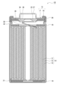
- FIG. 1 is a cross-sectional view of a non-aqueous electrolyte secondary battery that is an example of an embodiment
- FIG. 1 is a cross-sectional view of graphite particles of the present embodiment
- FIG. 1 is a cross-sectional view of a non-aqueous electrolyte secondary battery that is an example of an embodiment.
- the non-aqueous electrolyte secondary battery 10 shown in FIG. Insulating plates 18 and 19 arranged respectively in the respective parts, and a battery case 15 housing the above members.
- the battery case 15 is composed of a bottomed cylindrical case body 16 and a sealing member 17 that closes the opening of the case body 16 .
- Examples of the battery case 15 include a cylindrical or rectangular metal case, a resin case (pouch type battery) formed by laminating resin sheets, and the like.
- the case body 16 is, for example, a bottomed cylindrical metal container.
- a gasket 28 is provided between the case body 16 and the sealing member 17 to ensure hermeticity inside the battery.
- the case main body 16 has an overhanging portion 22 that supports the sealing member 17, for example, a portion of the side surface overhanging inward.
- the protruding portion 22 is preferably annularly formed along the circumferential direction of the case body 16 and supports the sealing member 17 on the upper surface thereof.
- the sealing body 17 has a structure in which a filter 23, a lower valve body 24, an insulating member 25, an upper valve body 26, and a cap 27 are layered in order from the electrode body 14 side.
- Each member constituting the sealing member 17 has, for example, a disk shape or a ring shape, and each member except for the insulating member 25 is electrically connected to each other.
- the lower valve body 24 and the upper valve body 26 are connected to each other at their central portions, and an insulating member 25 is interposed between their peripheral edge portions.
- the positive electrode lead 20 attached to the positive electrode 11 extends through the through hole of the insulating plate 18 toward the sealing member 17, and the negative electrode lead 21 attached to the negative electrode 12 extends toward the sealing member 17. It extends to the bottom side of the case body 16 through the outside of the insulating plate 19 .
- the positive electrode lead 20 is connected to the lower surface of the filter 23, which is the bottom plate of the sealing member 17, by welding or the like, and the cap 27, which is the top plate of the sealing member 17 electrically connected to the filter 23, serves as a positive electrode terminal.
- the negative lead 21 is connected to the inner surface of the bottom of the case body 16 by welding or the like, and the case body 16 serves as a negative terminal.
- the positive electrode 11, the negative electrode 12, the separator 13, and the nonaqueous electrolyte that constitute the nonaqueous electrolyte secondary battery 10 will be described in detail below.
- the positive electrode 11 is a long strip-shaped sheet member, and includes a positive electrode current collector and a positive electrode mixture layer disposed on the positive electrode current collector.
- the positive electrode current collector foils of metals such as aluminum and aluminum alloys that are stable in the potential range of the positive electrode, films having such metals arranged on the surface layer, and the like can be used.
- the positive electrode mixture layer includes, for example, a positive electrode active material, a binder, a conductive material, and the like.
- the positive electrode mixture layer is preferably formed on both sides of the positive electrode current collector.
- the positive electrode 11 is produced, for example, by coating a positive electrode mixture slurry containing a positive electrode active material, a binder, a conductive material, etc. on a positive electrode current collector, drying and rolling the coating film, and turning the positive electrode mixture layer into a positive electrode current collector. It can be manufactured by forming it on the body.
- the positive electrode active material is, for example, a lithium composite oxide capable of reversibly intercalating and deintercalating lithium.
- metal elements contained in the lithium composite oxide include Ni, Co, Mn, Al, B, Mg, Ti, V, Cr, Fe, Cu, Zn, Ga, Sr, Zr, Nb, In, Sn , Ta, W, and the like. Among them, it is preferable to contain at least one of Ni, Co, and Mn.
- An example of a suitable lithium composite oxide is represented by the general formula LiMO 2 (M is Ni and X, X is a metal element other than Ni, and the ratio of Ni to the total number of moles of metal elements excluding Li is is 50 mol % or more and 95 mol % or less).
- X in the above formula includes, for example, Co, Mn, Al, B, Mg, Ti, V, Cr, Fe, Cu, Zn, Ga, Sr, Zr, Nb, In, Sn, Ta, W, etc. .
- Examples of the conductive material contained in the positive electrode mixture layer include carbon black, acetylene black, ketjen black, graphene, fibrous carbon such as carbon nanotubes, and carbon materials such as graphite.
- the binder contained in the positive electrode mixture layer includes fluororesins such as polytetrafluoroethylene (PTFE) and polyvinylidene fluoride (PVdF), polyacrylonitrile (PAN), polyimide resins, acrylic resins, polyolefin resins, styrene-butadiene rubber (SBR), carboxymethyl cellulose (CMC) or salts thereof, polyacrylic acid (PAA) or salts thereof (PAA-Na, PAA-K, etc., may also be partially neutralized salts), polyethylene oxide (PEO), polyvinyl alcohol (PVA) and the like.
- fluororesins such as polytetrafluoroethylene (PTFE) and polyvinylidene fluoride (PVdF), polyacrylon
- the negative electrode 12 is a long strip-shaped sheet member, and includes a negative electrode current collector and a negative electrode mixture layer disposed on the negative electrode current collector.
- a negative electrode current collector for example, a foil of a metal such as copper or a copper alloy that is stable in the potential range of the negative electrode, a film having the metal on the surface layer, or the like can be used.
- the negative electrode mixture layer includes a negative electrode active material containing graphite particles and a Si-based material, and fibrous carbon.
- the negative electrode mixture layer 32 may additionally contain a binder or the like.
- the negative electrode 12 is formed by, for example, coating a negative electrode mixture slurry containing a negative electrode active material, fibrous carbon, a binder, etc. on a negative electrode current collector, drying and rolling the coating film, and forming a negative electrode mixture layer into a negative electrode collector. It can be manufactured by forming it on an electrical body.
- the graphite particles have a degree of graphitization in the range of 70-80, preferably in the range of 72-78, obtained by X-ray diffraction.
- the particles are harder than graphite particles having a degree of graphitization higher than the above range. Since the hard graphite particles are less likely to be crushed even when the negative electrode 12 is produced by rolling, appropriate voids are maintained in the negative electrode mixture layer, which is thought to contribute to the improvement of electrolyte permeability. If the degree of graphitization of the graphite particles is lower than the above range, side reactions with the non-aqueous electrolyte are accelerated, and the cycle characteristics of the battery tend to deteriorate.
- FIG. 2 is a cross-sectional view of the graphite particles of this embodiment.
- the graphite particle 30 has closed voids 34 (hereinafter referred to as internal voids 34) that are not connected from the inside of the particle to the particle surface, and and voids 36 (hereinafter referred to as external voids 36) connected to the particle surface.
- internal voids 34 closed voids 34
- external voids 36 voids 36
- the graphite particles 30 of the present embodiment have a particle internal porosity in the range of 1% to 5%.
- the particle internal porosity of the graphite particles 30 is in the range of 1% to 5%, preferably in the range of 2% to 5%.
- the particle internal porosity of the graphite particles is a two-dimensional value obtained from the ratio of the area of the internal voids of the graphite particles to the cross-sectional area of the graphite particles in the negative electrode mixture layer. Then, the particle internal porosity of the graphite particles is obtained by the following procedure.
- ⁇ Method for measuring internal porosity> Exposing a section of the negative electrode active material layer. Examples of the method of exposing the cross section include a method of cutting a part of the negative electrode and processing it with an ion milling device (eg, IM4000PLUS manufactured by Hitachi High-Tech) to expose the cross section of the negative electrode active material layer. (2) Using a scanning electron microscope, take a backscattered electron image of the cross section of the exposed negative electrode active material layer. The magnification for capturing the reflected electron image is 3,000 times to 5,000 times.
- an ion milling device eg, IM4000PLUS manufactured by Hitachi High-Tech
- the area of the graphite particle cross section refers to the area of the region surrounded by the outer periphery of the graphite particle, that is, the area of the entire cross section of the graphite particle.
- voids with a width of 3 ⁇ m or less may be difficult to distinguish between internal voids and external voids in image analysis. may be Then, from the calculated area of the graphite particle cross section and the area of the internal voids in the graphite particle cross section, the particle internal porosity of the graphite particles (area of internal voids in the cross section of the graphite particle ⁇ 100/area of the cross section of the graphite particle) is calculated.
- the particle internal porosity of the graphite particles is the average value of 10 graphite particles each.
- coke which is the main raw material
- coke which is the main raw material
- Graphite particles of a desired size are obtained by dividing.
- the internal porosity of the particles can be adjusted in the range of 1% to 5% depending on the particle size of the precursor after pulverization, the particle size of the precursor in an agglomerated state, and the like.
- the average particle diameter (volume-based median diameter D50) of the pulverized precursor is preferably in the range of 12 ⁇ m to 20 ⁇ m.
- the degree of graphitization of the graphite particles can be controlled by adjusting the firing temperature and firing time, for example.
- the firing temperature may be, for example, in the range of 2600°C to 2900°C.
- the baking time may be, for example, 10 hours or longer.
- the graphite particles of the present embodiment are not particularly limited to natural graphite, artificial graphite, or the like, but artificial graphite is preferable because it is easy to adjust the degree of graphitization and the internal porosity of the particles.
- the content of the graphite particles may be, for example, 90% by mass or more, or 95% by mass or more, relative to the total mass of the negative electrode active material.
- Si-based material that is the negative electrode active material examples include Si particles, alloy particles containing Si, and composite particles containing Si. These may be used alone or in combination of two or more.
- Si particles can be obtained, for example, by a vapor phase method or by pulverizing silicon chips, but they can be produced by any method.
- Alloy particles containing Si include, for example, alloys containing Si and metals selected from alkali metals, alkaline earth metals, transition metals, rare earth metals, or combinations thereof.
- the composite particles containing Si include, for example, a lithium ion conductive phase and Si particles dispersed in the lithium ion conductive phase.
- the lithium ion conductive phase is, for example, at least one selected from silicon oxide phases, silicate phases and carbon phases.
- the silicate phase contains, for example, at least one element selected from lithium, sodium, potassium, rubidium, cesium, francium, beryllium, magnesium, calcium, strontium, barium, and radium in terms of high lithium ion conductivity. preferably included.
- the silicate phase is preferably a silicate phase containing lithium (hereinafter sometimes referred to as a lithium silicate phase) because of its high lithium ion conductivity.
- Composite particles in which Si particles are dispersed in a silicon oxide phase are represented, for example, by the general formula SiO x (preferably in the range of 0 ⁇ x ⁇ 2, more preferably in the range of 0.5 ⁇ x ⁇ 1.6). be done.
- a composite particle in which Si particles are dispersed in a carbon phase is represented, for example, by the general formula Si x C y (preferably in the range of 0 ⁇ x ⁇ 1 and 0 ⁇ y ⁇ 1).
- a conductive film composed of a highly conductive material is formed on the surface of the particles of the Si-based material.
- conductive coatings include carbon coatings, metal coatings, and metal compound coatings. Carbon coatings are preferred from the viewpoint of electrochemical stability and the like.
- the carbon film can be formed by, for example, a CVD method using acetylene, methane, etc., a method of mixing coal pitch, petroleum pitch, phenol resin, etc. with a silicon-based active material and performing heat treatment.
- a conductive film may be formed by adhering a conductive filler such as carbon black to the particle surface of the Si-based material using a binder.
- the content of the Si-based material is in the range of 0.1% by mass to 5.0% by mass, preferably in the range of 1.0% by mass to 5.0% by mass, relative to the total mass of the negative electrode active material. be.
- the content of the Si-based material is within the above range, deterioration in the cycle characteristics of the battery is suppressed compared to when the content exceeds the above range, and the capacity of the battery can be increased compared to when the content is less than the above range. becomes.
- the fibrous carbon contained in the negative electrode mixture layer includes known materials used as conductive materials for batteries, such as carbon nanotubes (CNT), carbon nanofibers (CNF), and vapor grown carbon fibers (VGCF). , electrospun carbon fiber, polyacrylonitrile (PAN)-based carbon fiber, pitch-based carbon fiber, and the like.
- CNT carbon nanotubes
- CNF carbon nanofibers
- VGCF vapor grown carbon fibers
- electrospun carbon fiber polyacrylonitrile (PAN)-based carbon fiber
- PAN polyacrylonitrile
- the outermost diameter of fibrous carbon is, for example, in the range of 1 nm to 20 nm.
- the outermost diameter of fibrous carbon can be obtained by measuring the outer diameters of 50 arbitrary carbon fibrous carbons with a field emission scanning microscope (FE-SEM) or transmission electron microscope (TEM) and calculating the arithmetic mean.
- FE-SEM field emission scanning microscope
- TEM transmission electron microscope
- the fiber length of fibrous carbon is, for example, in the range of 0.1 ⁇ m to 20 ⁇ m.
- the fiber length of fibrous carbon can be determined by measuring the length of 50 arbitrary fibrous carbons with a field emission scanning microscope (FE-SEM) and calculating the arithmetic mean.
- FE-SEM field emission scanning microscope
- the fibrous carbon preferably contains carbon nanotubes, for example, in terms of suppressing deterioration of the cycle characteristics of the battery.
- Carbon nanotubes include single-walled carbon nanotubes, double-walled carbon nanotubes, and multi-walled carbon nanotubes.
- a single-walled carbon nanotube (SWCNT) is a carbon nanostructure in which one layer of graphene sheets constitutes a cylindrical shape, and a double-walled carbon nanotube has two layers of graphene sheets, which are concentrically stacked to form a single line.
- a multi-walled carbon nanotube is a carbon nanostructure in which three or more graphene sheets are concentrically laminated to form a single cylindrical shape.
- the graphene sheet refers to a layer in which carbon atoms of sp2 hybridized orbitals constituting a crystal of graphite (graphite) are positioned at vertexes of a regular hexagon.
- the shape of the carbon nanotube is not limited, but examples thereof include needle-like, cylindrical tube-like, fishbone-like (fishbone or cup laminated type), card-like (platelet), coil-like, and the like.
- the G/D ratio obtained by Raman spectroscopic measurement of carbon nanotubes (CNT) is preferably 40-130.
- the G/D ratio is the ratio of the peak intensity of G-Band (1550 cm -1 to 1600 cm -1 ) to the peak intensity of D-Band (1300 cm -1 to 1350 cm -1 ) in Raman spectroscopy. CNTs with a high G/D ratio indicate high crystallinity.
- the Raman spectroscopic spectrum of carbon nanotubes can be measured using a Raman spectrometer (eg, NRS-5500 manufactured by JASCO Corporation). For example, a carbon nanotube is dispensed onto a slide and flattened using a spatula to measure a prepared sample. Measurement conditions are, for example, as follows. Measurement time: 5 seconds Accumulation times: 2 Neutral density filter OD: 0.3 Objective lens magnification: 100 times Measurement range: 950 cm -1 to 1900 cm -1
- the content of fibrous carbon is, for example, 0.01% by mass to 0.1% by mass with respect to the total mass of the negative electrode active material in terms of increasing the capacity of the battery and suppressing deterioration of cycle characteristics. is preferred, and 0.01% by mass to 0.05% by mass is more preferred.
- the negative electrode mixture layer may contain a conductive material other than fibrous carbon in addition to fibrous carbon.
- conductive materials other than fibrous carbon include carbon black, acetylene black, and ketjen black.
- binder examples include the binders exemplified for the positive electrode 11 and the like.
- the content of the binder may be, for example, in the range of 0.5% by mass to 10% by mass with respect to the total mass of the negative electrode active material.
- separator 13 for example, a porous sheet having ion permeability and insulation is used. Specific examples of porous sheets include microporous thin films, woven fabrics, and non-woven fabrics. Suitable materials for the separator 13 include olefin resins such as polyethylene, polypropylene, copolymers containing at least one of ethylene and propylene, and cellulose. The separator 13 may have either a single layer structure or a laminated structure. A heat-resistant layer or the like may be formed on the surface of the separator 13 .
- the non-aqueous electrolyte contains a non-aqueous solvent and an electrolyte salt.
- Lithium salts such as LiFSI, LiTFSI, LiBF 4 , and LiPF 6 are used as electrolyte salts, for example.
- solvents include ethylene carbonate (EC), propylene carbonate (PC), dimethyl carbonate (DMC), ethyl methyl carbonate (EMC), diethyl carbonate (DEC), methyl acetate (MA), methyl propionate (MP), and the like. esters, ethers, nitriles, amides, and mixed solvents of two or more of these are used.
- the non-aqueous solvent may contain a halogen-substituted product obtained by substituting at least part of the hydrogen atoms of these solvents with halogen atoms such as fluorine.
- halogen-substituted compounds include fluorinated cyclic carbonates such as fluoroethylene carbonate (FEC), fluorinated chain carbonates, and fluorinated chain carboxylates such as methyl fluoropropionate (FMP).
- FEC fluoroethylene carbonate
- FMP fluorinated chain carboxylates
- Example 1 [Preparation of positive electrode] 95 parts by mass of LiCo0.979Zr0.001Mg0.01Al0.01O2 , 2.5 parts by mass of acetylene black (AB), and 2.5 parts by mass of polyvinylidene fluoride were mixed. , N-methyl-2-pyrrolidone (NMP) was added in an appropriate amount to prepare a positive electrode mixture slurry. Next, the positive electrode mixture slurry was applied to both surfaces of a positive electrode current collector made of an aluminum foil having a thickness of 15 ⁇ m, and the coating film was dried. After the dried coating film was rolled using a rolling roller, it was cut into a predetermined electrode plate size to prepare a positive electrode in which positive electrode mixture layers were formed on both sides of a positive electrode current collector.
- NMP N-methyl-2-pyrrolidone
- Coke was pulverized to an average particle size (median diameter D50) of 12 ⁇ m.
- Pitch as a binder was added to the pulverized coke, and the coke was agglomerated until the average particle size (median diameter D50) reached 17 ⁇ m.
- This aggregate was calcined at a temperature of 2800° C. for a predetermined time to be graphitized, and then sieved using a 250-mesh sieve to obtain graphite particles having an average particle diameter (median diameter D50) of 23 ⁇ m.
- the graphitization degree of the graphite particles was measured and found to be 75. The method for calculating the degree of graphitization is as described above.
- a negative electrode active material was prepared by mixing 97 parts by mass of the above graphite particles and 3 parts by mass of a Si-based material (composition: SiO).
- This negative electrode active material, carboxymethyl cellulose, styrene-butadiene rubber, and carbon nanotubes (CNT) were mixed in a mass ratio of 100:1.0:1.0:0.02.
- An appropriate amount of water was added to and mixed with this mixture to prepare a negative electrode mixture slurry.
- the negative electrode mixture slurry was applied to both surfaces of a negative electrode current collector made of copper foil having a thickness of 10 ⁇ m, and the coating film was dried. After the dried coating film was rolled using a rolling roller, it was cut into a predetermined electrode plate size to prepare a negative electrode in which negative electrode mixture layers were formed on both sides of a negative electrode current collector.
- the internal porosity of the graphite particles was measured and found to be 3%.
- the method for measuring the internal porosity of the particles is as described above.
- Ethylene carbonate (EC), propylene carbonate (PC) and ethylmethyl carbonate (EMC) were mixed in a volume ratio of 10:10:80.
- a non-aqueous electrolyte was prepared by dissolving LiPF 6 in the mixed solvent so as to have a concentration of 1.0 mol/L.
- a separator made of a polyethylene microporous membrane was placed between the positive electrode and the negative electrode, and these were wound, and a tape was adhered to the outermost peripheral surface to prepare a cylindrical wound electrode assembly. This electrode body was pressed into a flat electrode body.
- a sheet-like laminate material having a five-layer structure of resin layer (polypropylene)/adhesive layer/aluminum alloy layer/adhesive layer/resin layer (polypropylene) was prepared. This laminate material was folded back to form a bottom portion, thereby producing an exterior body having a cup-shaped electrode housing space. Then, in a glove box under an argon atmosphere, the electrode body and the non-aqueous electrolyte were stored in the electrode body storage space in the exterior body. After depressurizing the interior of the exterior body and impregnating the separator with the non-aqueous electrolyte, the opening of the exterior body was sealed to produce a non-aqueous electrolyte secondary battery.
- Example 2 Graphite particles were produced in the same manner as in Example 1, except that the sintering time for graphitizing the aggregates by sintering them at a temperature of 2800° C. was shorter than in Example 1. The graphitization degree of the graphite particles of Example 2 was measured and found to be 72. A negative electrode was produced in the same manner as in Example 1 except that the graphite particles were used, and a non-aqueous electrolyte secondary battery was produced in the same manner as in Example 1 using this negative electrode. From the negative electrode of Example 2, the internal porosity of the graphite particles was measured and found to be 3%.
- Example 3 In the preparation of the negative electrode, a non-aqueous electrolyte secondary was prepared in the same manner as in Example 1, except that a negative electrode active material was prepared by mixing 99 parts by mass of graphite particles and 1 part by mass of a Si-based material (composition: SiO). A battery was produced.
- Example 4 In the preparation of the negative electrode, a non-aqueous electrolyte secondary was prepared in the same manner as in Example 1, except that a negative electrode active material was prepared by mixing 96 parts by mass of graphite particles and 4 parts by mass of a Si-based material (composition: SiO). A battery was produced.
- Graphite particles were produced in the same manner as in Example 1, except that the aggregates were sintered at a temperature of 3000°C.
- the graphitization degree of the graphite particles of Comparative Example 1 was measured and found to be 85.
- the negative electrode was prepared in the same manner as in Example 1, except that only the graphite particles of Comparative Example 1 were used as the negative electrode active material, no Si-based material was used, and carbon nanotubes (CNT) were not added.
- a non-aqueous electrolyte secondary battery was produced in the same manner as in Example 1 using this negative electrode.
- the graphitized block-shaped molded body was pulverized and sieved using a 250-mesh sieve to obtain graphite particles having an average particle diameter (median diameter D50) of 23 ⁇ m.
- the graphitization degree of the graphite particles was measured and found to be 85.
- a negative electrode was prepared in the same manner as in Example 1, except that the graphite particles of Comparative Example 1 were used in the preparation of the negative electrode, and carbon nanotubes (CNT) were not added. Similarly, a non-aqueous electrolyte secondary battery was produced.
- Example 4 A negative electrode was prepared in the same manner as in Example 1 except that the graphite particles of Comparative Example 1 were used in the preparation of the negative electrode, and a non-aqueous electrolyte secondary battery was prepared in the same manner as in Example 1 using this negative electrode. .
- a negative electrode was prepared in the same manner as in Example 1 except that carbon nanotubes (CNT) were not added in the preparation of the negative electrode, and a non-aqueous electrolyte secondary battery was prepared in the same manner as in Example 1 using this negative electrode. bottom.
- CNT carbon nanotubes
- Example 6 A negative electrode was prepared in the same manner as in Example 1, except that the graphite particles of Example 2 were used in the preparation of the negative electrode, and carbon nanotubes (CNT) were not added. Similarly, a non-aqueous electrolyte secondary battery was produced.
- Example 7 A negative electrode was prepared in the same manner as in Example 1, except that a Si-based material was not used as the negative electrode active material and carbon nanotubes (CNT) were not added in the preparation of the negative electrode.
- a non-aqueous electrolyte secondary battery was produced in the same manner as in Example 1.
- Graphite particles were produced in the same manner as in Comparative Example 2, except that the agglomerates were sintered at a temperature of 2800°C. The graphitization degree of the graphite particles of Comparative Example 8 was measured and found to be 75.
- a negative electrode was prepared in the same manner as in Example 1 except that the graphite particles of Comparative Example 8 were used in the preparation of the negative electrode, and a non-aqueous electrolyte secondary battery was prepared in the same manner as in Example 1 using this negative electrode. . From the negative electrode of Comparative Example 8, the internal porosity of the graphite particles was measured and found to be 10%.
- a non-aqueous electrolyte secondary was prepared in the same manner as in Example 1, except that a negative electrode active material was prepared by mixing 94 parts by mass of graphite particles and 6 parts by mass of a Si-based material (composition: SiO). A battery was produced.
- Table 1 summarizes the test results for each example and each comparative example. However, regarding the battery capacity and the electrolyte permeation time, the result of Comparative Example 1 was used as a standard (100), and the results of other examples and comparative examples were shown as relative values.
- the negative electrode mixture layer includes a negative electrode active material containing graphite particles and a Si-based material, and fibrous carbon, the graphite particles have a degree of graphitization in the range of 70 to 80, and the graphite particles have an internal porosity of 1. % to 5%, and the content of the Si-based material is in the range of 0.1% by mass to 5.0% by mass with respect to the total mass of the negative electrode active material.
- Comparative Example 4 showed a higher battery capacity than Comparative Example 1, exhibited an effect of suppressing deterioration of cycle characteristics equal to or greater than that of Comparative Example 1, and improved the electrolyte permeability of the negative electrode from Comparative Example 1.
Landscapes
- Chemical & Material Sciences (AREA)
- General Chemical & Material Sciences (AREA)
- Chemical Kinetics & Catalysis (AREA)
- Electrochemistry (AREA)
- Engineering & Computer Science (AREA)
- Manufacturing & Machinery (AREA)
- Materials Engineering (AREA)
- Inorganic Chemistry (AREA)
- Composite Materials (AREA)
- Physics & Mathematics (AREA)
- Condensed Matter Physics & Semiconductors (AREA)
- General Physics & Mathematics (AREA)
- Battery Electrode And Active Subsutance (AREA)
Abstract
Priority Applications (4)
| Application Number | Priority Date | Filing Date | Title |
|---|---|---|---|
| JP2023576847A JPWO2023145603A1 (fr) | 2022-01-28 | 2023-01-19 | |
| CN202380018400.2A CN118613928A (zh) | 2022-01-28 | 2023-01-19 | 非水电解液二次电池用负极和非水电解液二次电池 |
| EP23746816.0A EP4471891A4 (fr) | 2022-01-28 | 2023-01-19 | Électrode négative pour batterie secondaire à électrolyte non aqueux et batterie secondaire à électrolyte non aqueux |
| US18/832,661 US20250105339A1 (en) | 2022-01-28 | 2023-01-19 | Negative electrode for nonaqueous electrolyte secondary battery, and nonaqueous electrolyte secondary battery |
Applications Claiming Priority (2)
| Application Number | Priority Date | Filing Date | Title |
|---|---|---|---|
| JP2022-011592 | 2022-01-28 | ||
| JP2022011592 | 2022-01-28 |
Publications (1)
| Publication Number | Publication Date |
|---|---|
| WO2023145603A1 true WO2023145603A1 (fr) | 2023-08-03 |
Family
ID=87471844
Family Applications (1)
| Application Number | Title | Priority Date | Filing Date |
|---|---|---|---|
| PCT/JP2023/001528 Ceased WO2023145603A1 (fr) | 2022-01-28 | 2023-01-19 | Électrode négative pour batterie secondaire à électrolyte non aqueux et batterie secondaire à électrolyte non aqueux |
Country Status (5)
| Country | Link |
|---|---|
| US (1) | US20250105339A1 (fr) |
| EP (1) | EP4471891A4 (fr) |
| JP (1) | JPWO2023145603A1 (fr) |
| CN (1) | CN118613928A (fr) |
| WO (1) | WO2023145603A1 (fr) |
Citations (9)
| Publication number | Priority date | Publication date | Assignee | Title |
|---|---|---|---|---|
| JPH08203502A (ja) | 1995-01-25 | 1996-08-09 | Matsushita Electric Ind Co Ltd | 非水電解液二次電池およびその負極の製造法 |
| JPH09320600A (ja) | 1996-05-29 | 1997-12-12 | Ucar Carbon Technol Corp | 電気化学的電池用緻密化炭素 |
| JPH11199322A (ja) | 1998-01-20 | 1999-07-27 | Hitachi Chem Co Ltd | 黒鉛粒子、その製造法、黒鉛ペースト、リチウム二次電池用負極及びリチウム二次電池 |
| WO2014143213A1 (fr) * | 2013-03-14 | 2014-09-18 | Energ2 Technologies, Inc. | Matériaux composites carbonés comprenant des modificateurs électrochimiques d'alliage au lithium |
| WO2015105167A1 (fr) * | 2014-01-09 | 2015-07-16 | 昭和電工株式会社 | Matériau actif d'électrode négative pour cellule secondaire lithium-ion |
| WO2015115242A1 (fr) * | 2014-01-31 | 2015-08-06 | 日東電工株式会社 | Pile secondaire à électrolyte non aqueux |
| JP2015185445A (ja) * | 2014-03-25 | 2015-10-22 | 三菱化学株式会社 | 非水系二次電池負極用炭素材、及び、非水系二次電池 |
| JP2016181405A (ja) * | 2015-03-24 | 2016-10-13 | 株式会社クレハ | 非水電解質二次電池負極用複合難黒鉛化性炭素質材料及び非水電解質二次電池負極用複合難黒鉛化性炭素質材料の製造方法 |
| WO2017007013A1 (fr) | 2015-07-09 | 2017-01-12 | 日本電気株式会社 | Batterie rechargeable au lithium-ion |
Family Cites Families (4)
| Publication number | Priority date | Publication date | Assignee | Title |
|---|---|---|---|---|
| WO2018146865A1 (fr) * | 2017-02-09 | 2018-08-16 | 株式会社村田製作所 | Accumulateur, bloc-batterie, véhicule électrique, outil électrique et dispositif électronique |
| CN108807848B (zh) * | 2018-05-11 | 2019-10-08 | 宁德时代新能源科技股份有限公司 | 负极极片及含有它的二次电池 |
| US12126013B2 (en) * | 2018-06-15 | 2024-10-22 | Panasonic Energy Co., Ltd. | Non-aqueous electrolyte secondary cell |
| WO2021085255A1 (fr) * | 2019-10-28 | 2021-05-06 | 株式会社村田製作所 | Électrode négative de batterie secondaire et batterie secondaire |
-
2023
- 2023-01-19 JP JP2023576847A patent/JPWO2023145603A1/ja active Pending
- 2023-01-19 US US18/832,661 patent/US20250105339A1/en active Pending
- 2023-01-19 CN CN202380018400.2A patent/CN118613928A/zh active Pending
- 2023-01-19 EP EP23746816.0A patent/EP4471891A4/fr active Pending
- 2023-01-19 WO PCT/JP2023/001528 patent/WO2023145603A1/fr not_active Ceased
Patent Citations (9)
| Publication number | Priority date | Publication date | Assignee | Title |
|---|---|---|---|---|
| JPH08203502A (ja) | 1995-01-25 | 1996-08-09 | Matsushita Electric Ind Co Ltd | 非水電解液二次電池およびその負極の製造法 |
| JPH09320600A (ja) | 1996-05-29 | 1997-12-12 | Ucar Carbon Technol Corp | 電気化学的電池用緻密化炭素 |
| JPH11199322A (ja) | 1998-01-20 | 1999-07-27 | Hitachi Chem Co Ltd | 黒鉛粒子、その製造法、黒鉛ペースト、リチウム二次電池用負極及びリチウム二次電池 |
| WO2014143213A1 (fr) * | 2013-03-14 | 2014-09-18 | Energ2 Technologies, Inc. | Matériaux composites carbonés comprenant des modificateurs électrochimiques d'alliage au lithium |
| WO2015105167A1 (fr) * | 2014-01-09 | 2015-07-16 | 昭和電工株式会社 | Matériau actif d'électrode négative pour cellule secondaire lithium-ion |
| WO2015115242A1 (fr) * | 2014-01-31 | 2015-08-06 | 日東電工株式会社 | Pile secondaire à électrolyte non aqueux |
| JP2015185445A (ja) * | 2014-03-25 | 2015-10-22 | 三菱化学株式会社 | 非水系二次電池負極用炭素材、及び、非水系二次電池 |
| JP2016181405A (ja) * | 2015-03-24 | 2016-10-13 | 株式会社クレハ | 非水電解質二次電池負極用複合難黒鉛化性炭素質材料及び非水電解質二次電池負極用複合難黒鉛化性炭素質材料の製造方法 |
| WO2017007013A1 (fr) | 2015-07-09 | 2017-01-12 | 日本電気株式会社 | Batterie rechargeable au lithium-ion |
Non-Patent Citations (1)
| Title |
|---|
| See also references of EP4471891A4 |
Also Published As
| Publication number | Publication date |
|---|---|
| CN118613928A (zh) | 2024-09-06 |
| JPWO2023145603A1 (fr) | 2023-08-03 |
| EP4471891A1 (fr) | 2024-12-04 |
| EP4471891A4 (fr) | 2025-10-08 |
| US20250105339A1 (en) | 2025-03-27 |
Similar Documents
| Publication | Publication Date | Title |
|---|---|---|
| JP7531165B2 (ja) | リチウムイオン二次電池用負極及びリチウムイオン二次電池 | |
| CN113410428B (zh) | 非水电解质二次电池用正极及非水电解质二次电池 | |
| JP7716670B2 (ja) | リチウムイオン二次電池用負極およびリチウムイオン二次電池 | |
| JP7228786B2 (ja) | 非水電解質二次電池用負極および非水電解質二次電池 | |
| CN113097444B (zh) | 非水电解质二次电池用负极及非水电解质二次电池 | |
| WO2023171564A1 (fr) | Batterie secondaire à solution électrolytique non aqueuse | |
| JP7602459B2 (ja) | 二次電池用負極活物質、及び二次電池 | |
| JP7766273B2 (ja) | 二次電池用負極及び二次電池 | |
| JP7372146B2 (ja) | 非水電解質二次電池用負極、及び非水電解質二次電池 | |
| CN119013801A (zh) | 正极活性物质及非水电解质二次电池 | |
| JP7668469B2 (ja) | 非水電解質二次電池用負極、及び非水電解質二次電池 | |
| WO2022070904A1 (fr) | Électrode négative de batterie secondaire et batterie secondaire | |
| WO2023149529A1 (fr) | Batterie secondaire à électrolyte non aqueux | |
| JP7288479B2 (ja) | 非水電解質二次電池 | |
| JP7349349B2 (ja) | 非水電解質二次電池用負極、及び非水電解質二次電池 | |
| CN119678282A (zh) | 非水电解质二次电池 | |
| WO2023145603A1 (fr) | Électrode négative pour batterie secondaire à électrolyte non aqueux et batterie secondaire à électrolyte non aqueux | |
| CN114342116A (zh) | 非水电解质二次电池用正极活性物质和非水电解质二次电池 | |
| US20250210630A1 (en) | Negative electrode active material for nonaqueous electrolyte secondary batteries, and nonaqueous electrolyte secondary battery | |
| JP7713646B2 (ja) | 非水電解質二次電池用正極活物質、及び非水電解質二次電池 | |
| EP4621901A1 (fr) | Batterie secondaire à électrolyte non aqueux | |
| JP7349346B2 (ja) | 非水電解質二次電池用負極、及び非水電解質二次電池 | |
| WO2025142651A1 (fr) | Batterie secondaire | |
| WO2024247965A1 (fr) | Batterie secondaire à électrolyte non aqueux | |
| TW202515010A (zh) | 非水電解質二次電池 |
Legal Events
| Date | Code | Title | Description |
|---|---|---|---|
| 121 | Ep: the epo has been informed by wipo that ep was designated in this application |
Ref document number: 23746816 Country of ref document: EP Kind code of ref document: A1 |
|
| ENP | Entry into the national phase |
Ref document number: 2023576847 Country of ref document: JP Kind code of ref document: A |
|
| WWE | Wipo information: entry into national phase |
Ref document number: 202380018400.2 Country of ref document: CN |
|
| WWE | Wipo information: entry into national phase |
Ref document number: 18832661 Country of ref document: US |
|
| WWE | Wipo information: entry into national phase |
Ref document number: 202447061347 Country of ref document: IN |
|
| NENP | Non-entry into the national phase |
Ref country code: DE |
|
| ENP | Entry into the national phase |
Ref document number: 2023746816 Country of ref document: EP Effective date: 20240828 |
|
| WWP | Wipo information: published in national office |
Ref document number: 18832661 Country of ref document: US |