WO2023176486A1 - 圧縮機 - Google Patents
圧縮機 Download PDFInfo
- Publication number
- WO2023176486A1 WO2023176486A1 PCT/JP2023/007878 JP2023007878W WO2023176486A1 WO 2023176486 A1 WO2023176486 A1 WO 2023176486A1 JP 2023007878 W JP2023007878 W JP 2023007878W WO 2023176486 A1 WO2023176486 A1 WO 2023176486A1
- Authority
- WO
- WIPO (PCT)
- Prior art keywords
- wall surface
- housing
- interstage
- flow path
- side wall
- Prior art date
- Legal status (The legal status is an assumption and is not a legal conclusion. Google has not performed a legal analysis and makes no representation as to the accuracy of the status listed.)
- Ceased
Links
Images


Classifications
-
- F—MECHANICAL ENGINEERING; LIGHTING; HEATING; WEAPONS; BLASTING
- F04—POSITIVE - DISPLACEMENT MACHINES FOR LIQUIDS; PUMPS FOR LIQUIDS OR ELASTIC FLUIDS
- F04D—NON-POSITIVE-DISPLACEMENT PUMPS
- F04D29/00—Details, component parts, or accessories
- F04D29/40—Casings; Connections of working fluid
- F04D29/42—Casings; Connections of working fluid for radial or helico-centrifugal pumps
- F04D29/44—Fluid-guiding means, e.g. diffusers
- F04D29/441—Fluid-guiding means, e.g. diffusers especially adapted for elastic fluid pumps
-
- F—MECHANICAL ENGINEERING; LIGHTING; HEATING; WEAPONS; BLASTING
- F04—POSITIVE - DISPLACEMENT MACHINES FOR LIQUIDS; PUMPS FOR LIQUIDS OR ELASTIC FLUIDS
- F04D—NON-POSITIVE-DISPLACEMENT PUMPS
- F04D17/00—Radial-flow pumps, e.g. centrifugal pumps; Helico-centrifugal pumps
- F04D17/08—Centrifugal pumps
- F04D17/10—Centrifugal pumps for compressing or evacuating
- F04D17/12—Multi-stage pumps
- F04D17/122—Multi-stage pumps the individual rotor discs being, one for each stage, on a common shaft and axially spaced, e.g. conventional centrifugal multi- stage compressors
-
- F—MECHANICAL ENGINEERING; LIGHTING; HEATING; WEAPONS; BLASTING
- F04—POSITIVE - DISPLACEMENT MACHINES FOR LIQUIDS; PUMPS FOR LIQUIDS OR ELASTIC FLUIDS
- F04D—NON-POSITIVE-DISPLACEMENT PUMPS
- F04D17/00—Radial-flow pumps, e.g. centrifugal pumps; Helico-centrifugal pumps
- F04D17/08—Centrifugal pumps
- F04D17/10—Centrifugal pumps for compressing or evacuating
- F04D17/12—Multi-stage pumps
- F04D17/122—Multi-stage pumps the individual rotor discs being, one for each stage, on a common shaft and axially spaced, e.g. conventional centrifugal multi- stage compressors
- F04D17/125—Multi-stage pumps the individual rotor discs being, one for each stage, on a common shaft and axially spaced, e.g. conventional centrifugal multi- stage compressors the casing being vertically split
-
- F—MECHANICAL ENGINEERING; LIGHTING; HEATING; WEAPONS; BLASTING
- F04—POSITIVE - DISPLACEMENT MACHINES FOR LIQUIDS; PUMPS FOR LIQUIDS OR ELASTIC FLUIDS
- F04D—NON-POSITIVE-DISPLACEMENT PUMPS
- F04D29/00—Details, component parts, or accessories
- F04D29/40—Casings; Connections of working fluid
- F04D29/42—Casings; Connections of working fluid for radial or helico-centrifugal pumps
- F04D29/4206—Casings; Connections of working fluid for radial or helico-centrifugal pumps especially adapted for elastic fluid pumps
Definitions
- the present disclosure relates to a compressor.
- Patent Documents 1 to 3 disclose technologies related to compressors.
- a multi-stage compressor having two or more compression stages.
- a multistage compressor includes, for example, a first compression stage that sucks in and compresses fluid, and a second compression stage that further compresses the fluid compressed by the first compression stage.
- the front compression stage and the rear compression stage are generally connected by piping, and the fluid from the front compression stage is introduced into the latter compression stage via a flow path in the piping. be done.
- This disclosure describes a compressor that can improve productivity.
- a compressor further compresses the fluid compressed by the first impeller using the second impeller.
- the compressor includes an impeller housing including a first housing that accommodates a first impeller and a second housing that accommodates a second impeller, and is connected to the impeller housing, and together with the impeller housing, transfers fluid from the first impeller to the second impeller. and an interstage part forming an interstage flow path to be introduced into the stage.
- the interstage flow path has at least one curved flow path.
- the curved channel includes an inner circumferential side wall surface that curves on the inner circumferential side in a cross section passing through the center line of the curved channel, and an outer circumferential side wall surface that curves on the outer circumferential side in the cross section.
- One of the inner peripheral side wall surface and the outer peripheral side wall surface is formed in the impeller housing.
- the other of the inner circumferential side wall surface and the outer circumferential side wall surface is formed as an interstage component.
- a compressor that can improve productivity is provided.
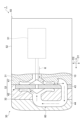
- FIG. 1 is a sectional view showing a compressor according to one embodiment.
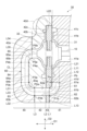
- FIG. 2 is an enlarged cross-sectional view of the compression unit of the compressor shown in FIG.
- FIG. 3 is an enlarged cross-sectional view of a part of the interstage flow path of the compression unit of FIG. 1.
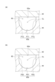
- FIG. 4(a) is a cross-sectional view of the interstage flow path taken along line A1-A1 in FIG.
- FIG. 4(b) is a cross-sectional view of the interstage flow path taken along line A2-A2 in FIG.
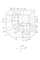
- FIG. 5 is a sectional view of the compression unit shown in FIG. 2, showing a state in which each component is divided.
- FIG. 6 is an enlarged cross-sectional view of a compression unit according to a comparative example.
- FIG. 1 is a sectional view showing a compressor according to one embodiment.
- FIG. 2 is an enlarged cross-sectional view of the compression unit of the compressor shown in FIG.
- FIG. 3 is an enlarged cross-
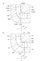
- FIG. 7A is an enlarged cross-sectional view of a part of the compression unit according to Reference Example 1.
- FIG. 7(b) is an enlarged cross-sectional view of a part of the compression unit according to Reference Example 2.
- FIG. 8(a) is an enlarged cross-sectional view of a part of the compression unit according to Reference Example 3.
- FIG. 8(b) is an enlarged cross-sectional view of a part of the compression unit according to Reference Example 4.
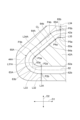
- FIG. FIG. 9 is an enlarged cross-sectional view of a part of the compression unit according to the first modification.
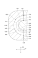
- FIG. 10 is a partially enlarged cross-sectional view of a compression unit according to Modification Example 2.
- FIG. 10 is a partially enlarged cross-sectional view of a compression unit according to Modification Example 2.
- a compressor further compresses the fluid compressed by the first impeller using the second impeller.
- the compressor includes an impeller housing including a first housing that accommodates a first impeller and a second housing that accommodates a second impeller, and is connected to the impeller housing, and together with the impeller housing, transfers fluid from the first impeller to the second impeller. and an interstage part forming an interstage flow path to be introduced into the stage.
- the interstage flow path has at least one curved flow path.
- the curved channel includes an inner circumferential side wall surface that curves on the inner circumferential side in a cross section passing through the center line of the curved channel, and an outer circumferential side wall surface that curves on the outer circumferential side in the cross section.
- One of the inner peripheral side wall surface and the outer peripheral side wall surface is formed in the impeller housing.
- the other of the inner circumferential side wall surface and the outer circumferential side wall surface is formed as an interstage component.
- the interstage flow path that introduces the fluid from the first impeller to the second impeller is formed by the impeller housing and the interstage parts.
- One of the inner circumferential side wall surface and the outer circumferential side wall surface of the curved flow path of the interstage flow path is formed in the impeller housing, and the other of the inner circumferential side wall surface and the outer circumferential side wall surface is formed in the interstage component.
- the inner circumference side wall surface and the outer circumference side wall surface of the curved flow path are formed in separate housings, respectively.
- the boundary line indicating the boundary between the impeller housing and the interstage component in the cross section may include a first boundary line and a second boundary line between the inner circumferential side wall surface and the outer circumferential side wall surface. good.
- the first boundary line may extend to intersect a straight line connecting the starting end of the inner circumferential wall surface and the starting end of the outer circumferential wall surface.
- the second boundary line may extend to intersect a straight line connecting the end of the inner wall surface and the end of the outer wall surface.
- the second boundary line may be directly or indirectly connected to the first boundary line between the inner peripheral side wall surface and the outer peripheral side wall surface.
- the distance between the inner peripheral wall surface and the outer peripheral wall surface in the direction perpendicular to the center line may be constant at each position along the center line. In this case, it is possible to suppress a situation in which a change in cross-sectional area occurs in each channel cross section of the curved channel. Thereby, it is possible to suppress a situation in which pressure loss occurs in the fluid flowing through the curved channel, and it is possible to suppress a decrease in performance of the compressor.
- the inner peripheral side wall surface may extend linearly in a cross section perpendicular to the center line of the curved channel.
- the outer circumferential side wall surface may be curved so as to bulge from the inner circumferential side wall surface toward the opposite side to the inner circumferential side wall surface. In this case, die-casting can be easily performed with the direction from the outer circumferential wall surface toward the inner circumferential wall surface being set as the die-cutting direction.
- the interstage component may be an interstage housing connected in series to the first housing via the second housing.
- the inner peripheral side wall surface may be formed on the second housing.
- the outer peripheral side wall surface may be formed on the interstage component.
- the interstage flow path can be easily formed by a simple operation of connecting the interstage housing, the second housing, and the first housing in series. Furthermore, by forming the inner circumferential side wall surface and the outer circumferential side wall surface separately into the second housing and the interstage parts in this way, it becomes possible to mold-cut the second housing and the interstage housing.
- the interstage component may be an interstage plate sandwiched between the first housing and the second housing.
- the inner peripheral side wall surface may be formed on the interstage component.
- the outer peripheral side wall surface may be formed on the first housing.
- the interstage flow path can be easily formed using the interstage plate between the first housing and the second housing.
- the interstage plate and the first housing can be die-cut.
- the first wall surface and the second wall surface may extend parallel to each other in a cross section passing through the center line, and may be formed on the impeller housing.
- the direction in which the straight flow path extends as the mold cutting direction, it becomes possible to mold cut the impeller housing in which the straight flow path is formed. Therefore, even if the interstage flow path has such a curved flow path and a straight flow path, each part can be die-cut.
- the compressor 1 shown in FIG. 1 is, for example, a series-type two-stage compressor.
- the compressor 1 includes a shaft 10, a compression unit 30, and a motor unit 50.
- the compression unit 30 includes a first impeller 31 , a second impeller 32 , and an impeller housing 33 .
- the first impeller 31 and the second impeller 32 are attached to one end of the shaft 10.
- the first impeller 31 and the second impeller 32 are arranged, for example, so that their back surfaces face each other with a gap between them.
- the first impeller 31 is, for example, arranged coaxially with the second impeller 32.
- the first impeller 31 is located between the second impeller 32 and the motor unit 50, for example.
- the impeller housing 33 has a first housing 41 that accommodates the first impeller 31 and a second housing 42 that accommodates the second impeller 32.
- the second housing 42 is connected in series to the first housing 41 in the axial direction D1 in which the shaft 10 extends.
- the first impeller 31 and the first housing 41 constitute a low-pressure side compression stage that sucks in and compresses the fluid R.
- the second impeller 32 and the second housing 42 constitute a high-pressure compression stage that further compresses the fluid R compressed by the low-pressure compression stage.
- the compression unit 30 further includes an interstage plate 43 and an interstage housing 44.
- Each of the interstage plate 43 and the interstage housing 44 is an interstage component connected to the impeller housing 33.
- the interstage plate 43 and the interstage housing 44 together with the impeller housing 33 have an interstage flow path 60 that introduces the fluid R from the first impeller 31 of the compression stage on the low pressure side into the second impeller 32 of the compression stage on the high pressure side.
- the interstage plate 43 is a plate-shaped component sandwiched between the first housing 41 and the second housing 42.
- the interstage housing 44 is a housing component that is connected to the second housing 42 from the side opposite to the first housing 41 in the axial direction D1.
- the interstage housing 44 is connected in series to the first housing 41 via the second housing 42 and the interstage plate 43 in the axial direction D1. Therefore, the interstage housing 44, the second housing 42, the interstage plate 43, and the first housing 41 are connected in series to each other in the axial direction D1.
- the configurations being connected in series in the axial direction D1 means that the configurations are arranged in the axial direction D1 and each configuration has a connecting surface that intersects with the axial direction D1.
- the interstage plate 43, the first housing 41, and the second housing 42 are separately provided members. That is, the interstage plate 43, the first housing 41, and the second housing 42 are each independent components.
- the compression unit 30 is configured by integrating the interstage plate 43, the first housing 41, and the second housing 42.
- known fastening means such as screws or bolts and nuts, or known joining means such as welding or fusion joining can be used. can.
- the motor unit 50 includes a motor 51 and a motor housing 52.
- the motor 51 is a drive source for driving the compression unit 30.
- the motor 51 is attached to the other end of the shaft 10. Inside the motor housing 52, the shaft 10 is rotatably supported by a bearing.
- Motor housing 52 accommodates motor 51.
- the motor housing 52 is connected in series with the first housing 41 in the axial direction D1.
- the motor housing 52, the first housing 41, the interstage plate 43, the second housing 42, and the interstage housing 44 are each independent parts, and the housing of the compressor 1 is configured by the combination thereof.
- FIG. 2 shows an enlarged view of the compression unit 30.
- the first housing 41 includes an inlet 41a, a diffuser channel 41b, and a scroll channel 41c.
- the suction port 41a is an opening coaxial with the shaft 10, and communicates with the inside of the motor housing 52 (see FIG. 1).
- the fluid R sucked from the suction port of the motor housing 52 flows into the suction port 41a.
- the first impeller 31 is arranged on the back side of the suction port 41a.
- the rotation of the first impeller 31 imparts velocity energy to the fluid R.
- the scroll passage 41c is formed to surround the first impeller 31.
- the diffuser passage 41b is formed between the first impeller 31 and the scroll passage 41c.
- the diffuser flow path 41b compresses the fluid R by converting velocity energy imparted to the fluid R into compression energy.
- the scroll passage 41c discharges the fluid R compressed in the diffuser passage 41b.
- the second housing 42 includes an inlet 42a, a diffuser channel 42b, a scroll channel 42c, and a discharge port 42d.
- the suction port 42a is an opening coaxial with the suction port 41a of the first housing 41, and faces opposite to the suction port 41a.
- the suction port 42a is connected to the scroll flow path 41c of the first housing 41 via the interstage flow path 60. Therefore, the fluid R from the scroll passage 41c flows into the suction port 42a via the interstage passage 60.
- the second impeller 32 is arranged on the back side of the suction port 42a. The rotation of the second impeller 32 imparts velocity energy to the fluid R.
- the scroll passage 42c is formed to surround the second impeller 32.
- the diffuser passage 42b is formed between the second impeller 32 and the scroll passage 42c.
- the diffuser flow path 42b further compresses the fluid R by converting the velocity energy imparted to the fluid R into compression energy.
- the scroll passage 42c discharges the compressed fluid R to the outside from the discharge port 42d.
- upper means the upper side in the vertical direction D2 when the compressor 1 is installed at the location where it is used
- lower means the lower side in the vertical direction D2.
- the shaft 10 is arranged so as to extend in the horizontal direction when the compressor 1 is installed at the location where it is used. Therefore, in this embodiment, the axial direction D1 is perpendicular to the vertical direction D2.
- the interstage channel 60 includes, for example, a curved channel 61, a straight channel 62, a curved channel 63, a straight channel 64, and a curved channel 65. These channels are formed on the same plane. That is, the center lines CL of these channels are included in the same plane.
- the same plane here may be, for example, a plane along the axial direction D1 and the vertical direction D2.
- the centerline CL of the interstage flow path 60 may be a line passing through the center of gravity of each flow path cross section perpendicular to the extending direction of the interstage flow path 60.
- FIG. 2 shows a cross section of the compression unit 30 taken along the center line CL on a plane along the axial direction D1 and the vertical direction D2.
- the curved flow path 61, the straight flow path 62, the curved flow path 63, the straight flow path 64, and the curved flow path 65 that constitute the interstage flow path 60 are used for the fluid R flowing through the interstage flow path 60. They are arranged in this order from upstream to downstream in the flow direction.
- the straight flow path 62 is located below the second impeller 32 and extends in the axial direction D1.
- straight channel 62 extends parallel to shaft 10 .
- the curved channel 61 is located below the first impeller 31 and extends in an arcuate manner between the outlet 41d of the scroll channel 41c and the straight channel 62. That is, the curved flow path 61 is curved so as to extend below the outlet 41d of the scroll flow path 41c and connect to the straight flow path 62 in the axial direction D1.
- the curved flow path 63, the straight flow path 64, and the curved flow path 65 are located on the opposite side of the first impeller 31 with respect to the second impeller 32 in the axial direction D1.
- the straight flow path 64 extends linearly in the vertical direction D2 at a position above the straight flow path 62 and below the shaft 10.
- the curved flow path 63 is arranged on the opposite side of the curved flow path 61 across the straight flow path 62 in the axial direction D1.
- the curved flow path 63 extends between the straight flow path 62 and the straight flow path 64 in a circular arc shape. That is, the curved flow path 63 is curved so as to extend upward from the straight flow path 62 and connect to the straight flow path 64 .
- the curved channel 65 is disposed on the opposite side of the curved channel 63 with the straight channel 62 interposed therebetween in the vertical direction D2.
- the curved flow path 65 extends in an arcuate manner between the straight flow path 64 and the suction port 42a. That is, the curved flow path 65 is curved so as to extend above the straight flow path 64 and connect to the suction port 42a in the axial direction D1.
- the curved channel 61, the curved channel 63, and the curved channel 65 have the same curvature.
- the curvature here may be based on the center line CL of each curved channel.
- the "curved flow path" is defined as a continuous curved portion of the interstage flow path 60 that is represented by one curvature in the cross section shown in FIG. 2 .
- the curved channel 61, the curved channel 63, and the curved channel 65 may have different curvatures.
- the curved flow path 61, the curved flow path 63, and the curved flow path 65 may be directly connected to each other without using a straight flow path.
- the curved flow path 61, the curved flow path 63, and the curved flow path 65 of this embodiment are formed by a combination of the first housing 41, the interstage plate 43, the second housing 42, and the interstage housing 44. be done.
- the curved flow path 61, the curved flow path 63, and the curved flow path 65 are comprised only of curved portions in the cross section shown in FIG.
- the curved channel 61, the curved channel 63, and the curved channel 65 are not limited to this form.
- the curved channel 61, the curved channel 63, and the curved channel 65 are not limited to this form. It may also include a flow path extending to.
- the curved channel 61 includes an inner circumferential wall surface 61 a that constitutes an inner circumferential wall surface of the curved channel 61 and an outer circumferential wall surface 61 b that constitutes an outer circumferential wall surface of the curved channel 61 .
- the inner wall surface 61a and the outer wall surface 61b are represented as arcuate curves.
- the inner circumferential wall surface 61a is curved in an arc shape at a position on the inner circumferential side, that is, a position radially inner than the outer circumferential wall surface 61b.
- the outer circumferential wall surface 61b is curved in an arc shape at a position on the outer circumferential side, that is, at a position radially outer than the inner circumferential wall surface 61a.
- the outer circumferential wall surface 61b is, for example, arranged concentrically with the inner circumferential wall surface 61a, and extends parallel to the inner circumferential wall surface 61a.
- the inner wall surface 61a may be a portion of the wall surface constituting the curved channel 61 that includes at least the inner arc-shaped curved portion shown in FIG.
- the outer circumferential wall surface 61b may be a portion of the wall surface constituting the curved channel 61 that includes at least an arcuate curved portion on the outer circumferential side shown in FIG.
- the outer peripheral wall surface 61b may be a portion excluding the inner peripheral wall surface 61a.
- a starting end Pa of the inner circumferential wall surface 61a and a starting end Pb of the outer circumferential wall surface 61b are connected to a wall surface constituting the outlet 41d of the scroll passage 41c.
- the starting end of a certain wall surface means one end of the wall surface located on the upstream side in the flow direction of the fluid R flowing through the interstage flow path 60 in the cross section shown in FIG.
- the terminal end of a certain wall surface means the other end of the wall surface located on the downstream side in the flow direction.
- the curved channel 63 includes an inner circumferential wall surface 63a that constitutes an inner circumferential wall surface of the curved channel 63, and an outer circumferential wall surface 63b that constitutes an outer circumferential wall surface of the curved channel 63.
- the inner wall surface 63a and the outer wall surface 63b are represented as arcuate curves.
- the inner circumferential wall surface 63a is curved in an arc shape at a position on the inner circumferential side, that is, a position radially inner than the outer circumferential wall surface 63b.
- the outer circumferential wall surface 63b is curved in an arc shape at a position on the outer circumferential side, that is, at a position radially outer than the inner circumferential wall surface 63a.
- the outer circumferential wall surface 63b is arranged concentrically with the inner circumferential wall surface 63a, and extends parallel to the inner circumferential wall surface 63a.
- the inner wall surface 63a may be a portion of the wall surface constituting the curved channel 63 that includes at least the inner arc-shaped curved portion shown in FIG.
- the outer circumferential side wall surface 63b may be a portion of the wall surface constituting the curved channel 63 that includes at least an arcuate curved portion on the outer circumferential side shown in FIG.
- the outer peripheral wall surface 63b may be a portion excluding the inner peripheral wall surface 63a.
- the curved channel 65 includes an inner circumferential wall surface 65a that constitutes an inner circumferential wall surface of the curved channel 65, and an outer circumferential wall surface 65b that constitutes an outer circumferential wall surface of the curved channel 65.
- the inner wall surface 65a and the outer wall surface 65b are represented as arcuate curves.
- the inner peripheral wall surface 65a is curved in an arc shape at a position on the inner peripheral side, that is, a position radially inner than the outer peripheral wall surface 65b.
- the outer circumferential wall surface 65b is curved in an arc shape at a position on the outer circumferential side, that is, a position radially outer than the inner circumferential wall surface 65a.
- the outer circumferential wall surface 65b is arranged concentrically with the inner circumferential wall surface 65a, and extends parallel to the inner circumferential wall surface 65a.
- the inner wall surface 65a may be a portion of the wall surface constituting the curved channel 65 that includes at least the inner arc-shaped curved portion shown in FIG.
- the outer circumferential side wall surface 65b may be a portion of the wall surface constituting the curved channel 65 that includes at least an arcuate curved portion on the outer circumferential side shown in FIG.
- the outer wall surface 65b may be a portion of the wall surface excluding the inner wall surface 65a.
- a terminal end P5a of the inner circumferential wall surface 65a and a terminal end P5b of the outer circumferential wall surface 65b are connected to a wall surface constituting the suction port 42a.
- the straight flow path 62 has a first wall surface 62a connected in the axial direction D1 to a terminal end P1a of the inner circumferential wall surface 61a and a starting end P2a of the inner circumferential wall surface 63a, and a terminal end P1b of the outer circumferential wall surface 61b and an outer circumferential wall surface 63b. and a second wall surface 62b connected to the starting end P2b in the axial direction D1.
- the first wall surface 62a and the second wall surface 62b are represented as mutually parallel straight lines extending in the axial direction D1.
- the first wall surface 62a may be a portion of the wall surfaces forming the straight flow path 62 that corresponds to the inner peripheral wall surface 61a and the inner peripheral wall surface 63a.
- the second wall surface 62b may be a portion of the wall surfaces forming the straight flow path 62 that corresponds to the outer peripheral wall surface 61b and the outer peripheral wall surface 63b.
- the second wall surface 62b may be a portion of the wall surface excluding the first wall surface 62a.
- the straight flow path 64 has a first wall surface 64a connected in the vertical direction D2 to a terminal end P3a of the inner peripheral wall surface 63a and a starting end P4a of the inner peripheral wall surface 65a, and a terminal end P3b of the outer peripheral wall surface 63b and the outer peripheral wall surface 65b. and a second wall surface 64b connected to the starting end P4b in the vertical direction D2.
- the first wall surface 64a and the second wall surface 64b are represented as mutually parallel straight lines extending in the vertical direction D2.
- the first wall surface 64a may be a portion of the wall surfaces forming the straight flow path 64 that corresponds to the inner peripheral wall surface 63a and the inner peripheral wall surface 65a.
- the second wall surface 64b may be a portion of the wall surfaces constituting the straight flow path 64 that corresponds to the outer circumference side wall surface 63b and the outer circumference side wall surface 65b.
- the second wall surface 64b may be a portion of the wall surface excluding the first wall surface 64a.
- the area of each channel cross section of the interstage channel 60 is, for example, constant. In other words, the area of the cross section of the interstage flow path 60 at any position along the center line CL is the same as the area of the cross section of the interstage flow path 60 at any other position along the center line CL. is set to . Therefore, the cross-sectional area of the straight channel 62, the straight channel 64, the curved channel 61, the curved channel 63, and the curved channel 65 are the same.
- the cross-sectional area of each flow path being the same is not limited to the case where the cross-sectional area of each flow path is strictly the same as each other, and the cross-sectional area of each flow path may include a certain range of tolerance.
- the permissible error within a certain range means, for example, an error in the cross-sectional area of each flow path within a range where the pressure loss occurring in the fluid R flowing through each flow path is allowable.
- FIG. 3 shows an enlarged view of the vicinity of the curved flow path 63 of the interstage flow path 60.
- the distance between the outer peripheral wall surface 63b and the inner peripheral wall surface 63a is a constant distance d at each position along the extending direction of the center line CL.
- the distance between the outer wall surface 63b and the inner wall surface 63a at any position along the center line CL is the distance between the outer wall surface 63b and the inner wall surface at any other position along the center line CL.
- 63a that is, a constant distance d).
- the distance between the outer circumferential wall surface 63b and the inner circumferential wall surface 63a means the distance between the outer circumferential wall surface 63b and the inner circumferential wall surface 63a in the direction perpendicular to the center line CL in the cross section shown in FIG.
- 61a and the distance between the outer peripheral wall surface 65b and the inner peripheral wall surface 65a of the curved channel 65 may also be a constant distance d at each position along the extending direction of the center line CL.
- FIG. 4(a) shows a cross-sectional shape of the curved channel 63 in a plane perpendicular to the center line CL.
- the cross-sectional shape of the curved channel 63 is not circular but U-shaped.
- the inner circumferential wall surface 63a constituting the curved channel 63 extends linearly in the cross section shown in FIG. 4(a). Therefore, the inner peripheral wall surface 63a constitutes a plane extending in the direction along the center line CL and in the direction perpendicular to the center line CL.
- FIG. 4(a) shows a cross-sectional shape of the curved channel 63 in a plane perpendicular to the center line CL.
- the outer circumferential wall surface 63b is curved so as to bulge toward the opposite side from the inner circumferential wall surface 63a. Therefore, the outer peripheral side wall surface 63b forms a curved surface that extends along the direction along the center line CL and is bent in a direction perpendicular to the center line CL.
- the outer wall surface 63b has an arcuate curved portion P11 that curves in a direction opposite to the inner wall surface 63a, and a curved portion P11 and the inner wall surface 63a. It includes a pair of connecting straight parts P12 and P13.
- the pair of straight portions P12 and P13 extend linearly from both ends of the inner peripheral wall surface 63a in a direction perpendicular to the inner peripheral wall surface 63a, and are connected to both ends of the curved portion P11.
- the pair of straight portions P12 and P13 extend parallel to each other.
- the curved flow path 61 and the curved flow path 65 also have the same cross-sectional shape as the curved flow path 63.
- FIG. 4(b) shows the cross-sectional shape of the straight flow path 62 in a plane perpendicular to the center line CL.
- the straight channel 62 has the same cross-sectional shape as the curved channel 63, for example.
- the first wall surface 62a constituting the straight channel 62 extends linearly in the cross section shown in FIG. 4(b). Therefore, the first wall surface 62a constitutes a plane extending in the direction along the center line CL and in the direction perpendicular to the center line CL, like the inner peripheral wall surface 63a.
- the second wall surface 62b is curved so as to bulge toward the opposite side from the first wall surface 62a in the cross section shown in FIG. 4(b). Therefore, the second wall surface 62b forms a curved surface that extends in the direction along the center line CL and is bent in a direction perpendicular to the center line CL, like the outer peripheral side wall surface 63b.
- the second wall surface 62b has an arc-shaped curved portion P21 that curves in a direction opposite to the first wall surface 62a, and connects the curved portion P21 and the first wall surface 62a. It includes a pair of straight portions P22 and P23.
- the pair of straight portions P22 and P23 extend linearly from both ends of the first wall surface 62a in a direction perpendicular to the first wall surface 62a, and are connected to both ends of the curved portion P21.
- the pair of straight portions P22 and P23 extend parallel to each other.
- the straight flow path 64 also has the same cross-sectional shape as the straight flow path 62.
- the interstage flow path 60 having the above configuration is formed by a combination of the first housing 41, the interstage plate 43, the second housing 42, and the interstage housing 44, as described above. That is, the wall surface constituting the interstage flow path 60 is divided into the first housing 41 , the interstage plate 43 , the second housing 42 , and the interstage housing 44 .
- boundary lines L1, L2, and L3 indicating boundaries between the first housing 41, the interstage plate 43, the second housing 42, and the interstage housing 44 are shown.
- a boundary line L1 indicates a boundary between the first housing 41 and the interstage plate 43.
- a boundary line L2 indicates a boundary between the interstage plate 43 and the second housing 42.
- a boundary line L3 indicates a boundary between the second housing 42 and the interstage housing 44.
- the boundary line L1 extends in the vertical direction D2 so as to pass through the curved flow path 61 of the interstage flow path 60.
- the boundary line L1 includes a boundary line L11, a boundary line L12, and a boundary line L13.
- the boundary line L11 extends in the vertical direction D2 between the starting end Pa of the inner peripheral wall surface 61a and the starting end Pb of the outer peripheral wall surface 61b.
- the boundary line L11 extends in the vertical direction D2 so as to be in contact with the starting end Pa of the inner peripheral side wall surface 61a.
- the boundary line L11 passes through the scroll channel 41c.
- the lower end of the boundary line L11 is located, for example, between the inner peripheral wall surface 61a and the center line CL.
- the boundary line L13 extends in the vertical direction D2 below the boundary line L11 and at a position shifted from the boundary line L11 in the axial direction D1.
- the boundary line L13 extends in the vertical direction D2, for example, so as to contact or pass through the terminal end P1b of the outer peripheral side wall surface 61b.
- the upper end of the boundary line L13 is located at the same position as the lower end of the boundary line L11 in the vertical direction D2.
- the boundary line L12 connects the lower end of the boundary line L11 and the upper end of the boundary line L13 in the axial direction D1.
- the boundary line L12 extends in the axial direction between the terminal end P1a of the inner circumferential wall surface 61a and the terminal end P1b of the outer circumferential wall surface 61b, more specifically, between the terminal end P1a of the inner circumferential wall surface 61a and the center line CL. It extends to D1.
- the boundary line L12 may extend in the axial direction D1 so as to be in contact with the terminal end P1a of the inner peripheral side wall surface 61a.
- the entire portion of the inner peripheral side wall surface 61a from the starting end Pa to the terminal end P1a is arranged on one side with the boundary line L1 in between.
- the entire portion of the outer peripheral side wall surface 61b from the starting end Pb to the ending end P1b is arranged on the other side with the boundary line L1 in between.
- the boundary line L2 is located between the boundary line L1 and the boundary line L3, and extends in the vertical direction D2 so as to pass through the straight flow path 62 of the interstage flow path 60.
- the boundary line L2 includes a boundary line L21 and a boundary line L22.
- the boundary line L21 extends parallel to the boundary line L11 and the boundary line L13 with an interval between them.
- the boundary line L21 extends in the vertical direction D2 so as to pass through the scroll passage 42c.
- the boundary line L22 extends from the upper end of the boundary line L21 in the axial direction D1, and is connected to the boundary line L11 of the boundary line L1.
- the boundary line L3 extends in the vertical direction D2 so as to pass through the curved flow path 63 and the curved flow path 65 of the interstage flow path 60.
- the boundary line L3 includes a boundary line L31 (first boundary line), a boundary line L32 (second boundary line), a boundary line L33, a boundary line L34, and a boundary line L35.
- the boundary line L31 extends in the vertical direction D2 between the terminal end P3a of the inner peripheral side wall surface 63a and the terminal end P3b of the outer peripheral side wall surface 63b.
- the boundary line L31 extends in the vertical direction D2 so as to be in contact with the terminal end P3a of the inner peripheral side wall surface 63a.
- the lower end of the boundary line L31 is located, for example, between the inner peripheral side wall surface 63a and the center line CL.
- the boundary line L31 extends in the vertical direction D2 between the starting end P4a of the inner peripheral side wall surface 65a and the starting end P4b of the outer peripheral side wall surface 65b.
- the boundary line L31 extends in the vertical direction D2 so as to be in contact with the starting end P4a of the inner peripheral side wall surface 65a.
- the lower end of the boundary line L31 is located, for example, between the inner peripheral side wall surface 63a and the center line CL.
- the upper end of the boundary line L31 is located, for example, between the inner peripheral side wall surface 65a and the center line CL.
- the boundary line L33 extends in the vertical direction D2 below the boundary line L31 and at a position shifted from the boundary line L31 toward the boundary line L2 side in the axial direction D1.
- the boundary line L33 extends in the vertical direction D2, for example, so as to be in contact with the starting end P2b of the outer peripheral side wall surface 63b, or to pass through the starting end P2b.
- the upper end of the boundary line L33 is located at the same position as the lower end of the boundary line L31 in the vertical direction D2.
- the boundary line L32 connects the lower end of the boundary line L31 and the upper end of the boundary line L33 in the axial direction D1.
- the boundary line L32 extends in the axial direction between the starting end P2a of the inner circumferential wall surface 63a and the starting end P2b of the outer circumferential wall surface 63b, more specifically, between the starting end P2a of the inner circumferential wall surface 63a and the center line CL. It extends to D1.
- the boundary line L32 may extend in the axial direction D1 so as to be in contact with the starting end P2a of the inner peripheral side wall surface 63a.
- the boundary line L34 extends in the vertical direction D2 at a position above the boundary line L31 and shifted from the boundary line L31 toward the boundary line L2 side in the axial direction D1.
- the boundary line L34 extends in the vertical direction D2, for example, so as to contact or pass through the terminal end P5b of the outer peripheral side wall surface 65b.
- the lower end of the boundary line L34 is located at the same position as the upper end of the boundary line L31 in the vertical direction D2.
- the boundary line L35 connects the upper end of the boundary line L31 and the lower end of the boundary line L34 in the axial direction D1.
- the boundary line L35 extends in the axial direction between the terminal end P5a of the inner circumferential wall surface 65a and the terminal end P5b of the outer circumferential wall surface 65b, more specifically, between the terminal end P5a of the inner circumferential wall surface 65a and the center line CL. It extends to D1.
- the boundary line L35 may extend in the axial direction D1 so as to be in contact with the terminal end P5a of the inner peripheral side wall surface 65a.
- the entire portion of the inner peripheral side wall surface 63a from the starting end P2a to the terminal end P3a is arranged on one side with the boundary line L3 in between.
- the entire portion of the outer peripheral side wall surface 63b from the starting end P2b to the ending end P3b is arranged on the other side with the boundary line L3 in between.
- the entire portion of the inner peripheral side wall surface 65a from the starting end P4a to the ending end P5a is arranged on one side with the boundary line L3 in between.
- the entire portion of the outer peripheral side wall surface 65b from the starting end P4b to the ending end P5b is arranged on the other side with the boundary line L3 in between.
- FIG. 5 shows a state in which the first housing 41, the interstage plate 43, the second housing 42, and the interstage housing 44 are separated from each other at each boundary line L1, L2, and L3.
- a boundary line L1 passing through the curved channel 61 separates the inner peripheral wall surface 61a and the outer peripheral wall surface 61b of the curved channel 61.
- the outer peripheral wall surface 61b located on one side across the boundary line L1 that is, the entire portion of the outer peripheral wall surface 61b from the starting end Pb to the terminal end P1b) is formed in the first housing 41.
- the inner circumferential wall surface 61a located on the other side across the boundary line L1 (that is, the entire portion of the inner circumferential wall surface 61a from the starting end Pa to the terminal end P1a) is formed in the interstage plate 43. That is, the inner peripheral wall surface 61a and the outer peripheral wall surface 61b, which constitute the wall surface of the curved flow path 61, are formed separately on the interstage plate 43 and the first housing 41, respectively.
- the first housing 41 includes dividing surfaces S11a, S12a, and S13a formed by dividing at the boundary line L1.
- the dividing surface S11a is a plane formed by dividing along the boundary line L11, and extends in the vertical direction D2 in the cross section shown in FIG.
- the dividing surface S13a is a plane formed by dividing along the boundary line L13, and extends in the vertical direction D2 in the cross section shown in FIG. For example, the dividing surface S13a is shifted toward the straight flow path 62 in the axial direction D1 with respect to the dividing surface S11a.
- the dividing surface S12a is a plane formed by dividing along the boundary line L12, and extends in the axial direction D1 in the cross section shown in FIG.
- the dividing surface S12a connects the dividing surface S11a and the dividing surface S13a in the axial direction D1.
- the dividing surface S12a is formed perpendicular to the dividing surface S11a and the dividing surface S13a.
- the interstage plate 43 includes dividing surfaces S11b, S12b, and S13b formed by dividing at the boundary line L1.
- the dividing surface S11b is a plane formed by dividing along the boundary line L11, and extends in the vertical direction D2 in the cross section shown in FIG.
- the dividing surface S11b extends parallel to the dividing surface S11a.
- the dividing surface S13b is a plane formed by dividing along the boundary line L13, and extends in the vertical direction D2 in the cross section shown in FIG. For example, the dividing surface S13b is shifted toward the straight flow path 62 in the axial direction D1 with respect to the dividing surface S11b.
- the dividing surface S12b is a plane formed by dividing along the boundary line L12, and extends in the axial direction D1 in the cross section shown in FIG.
- the dividing surface S12b connects the dividing surface S11b and the dividing surface S13b in the axial direction D1.
- the dividing surface S12b is formed perpendicular to the dividing surface S11b and the dividing surface S13b.
- a boundary line L3 passing through the curved channel 63 and the curved channel 65 separates the inner circumferential side wall surface 63a and the outer circumferential side wall surface 63b of the curved channel 63, and also separates the inner circumferential side wall surface 65a and the outer circumferential side of the curved channel 65.
- the wall surface 65b is separated from the wall surface 65b.
- the entire portion up to P5b) is formed on the interstage plate 43. That is, the inner circumferential wall surface 63a and the outer circumferential wall surface 63b, which constitute the wall surface of the curved channel 63, are formed separately in the second housing 42 and the interstage plate 43, respectively.
- An inner circumferential wall surface 63a and an outer circumferential wall surface 63b, which constitute the wall surface of the curved channel 63, are formed separately in the second housing 42 and the interstage plate 43, respectively.
- the second housing 42 includes dividing surfaces S31a, S32a, S33a, S34a, and S35a formed by dividing at the boundary line L3.
- the dividing surface S31a is a plane formed by dividing along the boundary line L31, and extends in the vertical direction D2 in the cross section shown in FIG.
- the dividing surface S33a is a plane formed by dividing along the boundary line L33, and extends in the vertical direction D2 in the cross section shown in FIG.
- the dividing surface S34a is a plane formed by dividing along the boundary line L34, and extends in the vertical direction D2 in the cross section shown in FIG.
- the dividing surface S33a and the dividing surface S34a are shifted toward the straight flow path 62 in the axial direction D1 with respect to the dividing surface S31a.
- the dividing surface S32a is a plane formed by dividing along the boundary line L32, and extends in the axial direction D1 in the cross section shown in FIG.
- the dividing surface S32a connects the dividing surface S31a and the dividing surface S32a in the axial direction D1.
- the dividing surface S35a is a plane formed by dividing along the boundary line L35, and extends in the axial direction D1 in the cross section shown in FIG.
- the dividing surface S35a connects the dividing surface S31a and the dividing surface S34a in the axial direction D1.
- the dividing surface S32a and the dividing surface S35a are formed perpendicular to the dividing surface S31a, the dividing surface S33a, and the dividing surface S34a.
- the interstage housing 44 includes dividing surfaces S31b, S32b, S33b, S34b, and S35b formed by dividing at the boundary line L3.
- the dividing surface S31b is a plane formed by dividing along the boundary line L31, and extends in the vertical direction D2 in the cross section shown in FIG.
- the dividing surface S33b is a plane formed by dividing along the boundary line L33, and extends in the vertical direction D2 in the cross section shown in FIG.
- the dividing surface S34b is a plane formed by dividing along the boundary line L34, and extends in the vertical direction D2 in the cross section shown in FIG.
- the dividing surface S33b and the dividing surface S34b are shifted toward the straight flow path 62 in the axial direction D1 with respect to the dividing surface S31b.
- the dividing surface S32b is a plane formed by dividing along the boundary line L32, and extends in the axial direction D1 in the cross section shown in FIG.
- the dividing surface S32b connects the dividing surface S31b and the dividing surface S32b in the axial direction D1.
- the dividing surface S35b is a plane formed by dividing along the boundary line L35, and extends in the axial direction D1 in the cross section shown in FIG.
- the dividing surface S35b connects the dividing surface S31b and the dividing surface S34b in the axial direction D1.
- the dividing surface S32b and the dividing surface S35b are formed perpendicular to the dividing surface S31b, the dividing surface S33b, and the dividing surface S34b.
- each part constituting the housing of the compression unit 30 i.e., the first housing 41, the interstage
- the shapes of the plate 43, the second housing 42, and the interstage housing 44 are such that they can be cut out with the axial direction D1 as the cutting direction.
- the term "mold” refers to, for example, a mold for casting.
- An annular sealing member such as an O-ring may be installed at the connection portion of the interstage flow path 60 in each component. In this case, the occurrence of leakage of the fluid R flowing through the interstage flow path 60 is suppressed.
- a first housing 141 housing the first impeller 131 and a second housing 142 housing the second impeller 132 are connected by a pipe 170.
- An interstage flow path 160 that introduces the fluid R from the first impeller 131 to the second impeller 132 is formed inside the pipe 170 .
- An interstage plate 143 is arranged between the first housing 141 and the second housing 142.
- the interstage flow path can be formed without using piping, so mass production costs can be suppressed.
- the housing can be formed by die-casting, which is inexpensive to manufacture, mass production costs can be further reduced.
- the housing needs to have a shape that can be cut out.
- the interstage flow path connecting the low pressure side compression stage and the high pressure side compression stage has one or more curved flow paths. Such a curved flow path may become a factor that hinders mold removal of the housing.
- FIG. 7(a) shows a configuration in which an interstage flow path 160 having a curved flow path 163 is formed within the housing of the compression unit.
- the curved flow path 163 exists in this way, in order to make the housing into a shape that can be cut out, it is divided into two parts (for example, the second housing 242 and the interstage housing 244) at a position passing through the curved flow path 163. It is possible to do so.
- the boundary line L103 indicating the boundary between the second housing 242 and the interstage housing 244 is drawn in the vertical direction D2 between the terminal end P103a of the inner circumferential side wall surface 163a of the curved flow path 163 and the terminal end P103b of the outer circumferential side wall surface 163b.
- the boundary line L103 intersects the outer peripheral side wall surface 163b and divides the outer peripheral side wall surface 163b into a portion P111 and a portion P112.
- the portion P111 of the outer wall surface 163b and the inner wall surface 163a are formed in the same second housing 242.
- the second housing 242 cannot be die-cut using the axial direction D1 as the die-cutting direction.
- a boundary line L203 indicating the boundary between the second housing 342 and the interstage housing 344 is located between the starting end P102a of the inner circumferential wall surface 163a of the curved channel 163 and the outer circumferential wall surface 163b.
- the inner peripheral wall surface 163a and the outer peripheral wall surface 163b are formed in the same interstage housing 344.
- the interstage housing 344 cannot be die-cut using the axial direction D1 as the die-cutting direction. Therefore, each part cannot be formed by die-casting along the boundary lines L103 and L203 as shown in FIGS. 7(a) and 7(b).
- the starting end P202b and the ending end P203b of the outer wall surface 263b are located on one side across the boundary line L303, and the starting end P202a and the ending end P203a of the inner peripheral wall surface 263a are located on the other side across the boundary line L303. That is, the inner peripheral wall surface 263a and the outer peripheral wall surface 263b are formed separately into the second housing 442 and the interstage housing 444.
- the second housing 442 and the interstage housing 444 can be formed by die-casting.
- the distance between the outer circumference side wall surface 263b and the inner circumference side wall surface 263a does not become a constant distance d, but becomes a distance d1 larger than the distance d. ing.
- the cross-sectional area of the curved channel 263 changes. Such a change in the cross-sectional area of the curved channel 263 can affect the flow of the fluid R flowing through the curved channel 263.
- FIG. 8(b) shows the same configuration as the compressor 1 according to the embodiment described above.
- the boundary line L31 of the boundary line L3 extends in the vertical direction D2 between the terminal end P3a of the inner peripheral side wall surface 63a and the terminal end P3a of the outer peripheral side wall surface 63b.
- the boundary line L33 extends in the axial direction D1 between the starting end P2a of the inner peripheral side wall surface 63a and the starting end P2a of the outer peripheral side wall surface 63b, and is connected to the boundary line L31.
- Boundary line L32 extends downward from boundary line L33.
- the inner circumferential side wall surface 63a and the outer circumferential side wall surface 63b are separated from the second housing 42 and the interstage housing 44, as in the example shown in FIG. 8(a).
- the housing 44 is formed separately from the housing 44.
- both the second housing 42 and the interstage housing 44 have shapes that can be cut out.
- each component of the compression unit 30 can be molded by die-casting, which is low in manufacturing cost, so productivity can be improved. Thereby, mass production costs can be suppressed.
- each component in the cross section perpendicular to the center line CL of the curved channel 63, the inner circumferential wall surface 63a extends linearly, and the outer circumferential wall surface 63b is opposite to the inner circumferential wall surface 63a. It is curved so that it bulges out to the side. According to this configuration, each component can be easily die-cast with the direction from the outer circumferential wall surface 63b toward the inner circumferential wall surface 63a as the die-cutting direction.
- the interstage housing 44 is connected in series to the first housing 41 via the second housing 42 to form the interstage flow path 60.
- the interstage flow path 60 can be easily formed by a simple operation of connecting the interstage housing 44, the second housing 42, and the first housing 41 in series.
- the interstage plate 43 is sandwiched between the first housing 41 and the second housing 42 to form the interstage flow path 60. With this configuration, the interstage flow path 60 can be easily formed using the interstage plate 43.
- the linear flow path 62 includes a first wall surface 62a and a second wall surface 62b that linearly extend parallel to each other.
- the first wall surface 62a and the second wall surface 62b are formed on the second housing 42.
- the second housing 42 can be die-cut using the axial direction D1 in which the straight flow path 62 extends as the die-cutting direction. Therefore, even if the interstage flow path 60 has the curved flow path 63 and the straight flow path 62 in this way, each part can be molded.
- the configuration of the curved channel 63 of the interstage channel 60 has been mainly explained, but the other curved channels 61 and 65 can be similarly explained.
- the "curved channel” of the present disclosure may be understood as any of the curved channels 61, 63, and 65.
- a case has been described in which the "straight channel” of the present disclosure is applied to the straight channel 62, but the “straight channel” of the present disclosure may be applied to other straight channels 64.
- the "interstage flow path" of the present disclosure only needs to have at least one curved flow path, and does not need to have a straight flow path.
- a straight channel 64A connecting the curved channel 63A and the curved channel 65A extends in a direction inclined from the vertical direction D2.
- the straight flow path 64A extends in a direction making an acute angle with respect to the straight flow path 62.
- the curved flow path 65A is disposed at a position shifted toward the suction port 42a in the axial direction D1 with respect to the curved flow path 63A.
- the boundary line L3A indicating the boundary between the interstage housing 44A and the second housing 42A has a boundary line L31A (second boundary line) instead of the boundary line L31.
- the boundary line L31A extends upward from the boundary line L33 (first boundary line), curves along the inner circumference side wall surface 63a so as to touch the terminal end P3a of the inner circumference side wall surface 63a, and then curves toward the first wall surface 64a. It extends linearly along the boundary line L35 and is connected to the boundary line L35.
- the second housing 42A and the interstage housing 44A are divided by the boundary line L3A, so that the inner peripheral side wall surface 63a of the curved flow path 63A and A first wall surface 64a of the straight flow path 64A and an inner wall surface 65a of the curved flow path 65A are formed in the second housing 42A. Further, an outer peripheral wall surface 63b of the curved flow path 63A, a second wall surface 64b of the straight flow path 64A, and an outer peripheral wall surface 65b of the curved flow path 65A are formed in the interstage housing 44A.
- each part can be made into a shape that can be cut out. Furthermore, similarly to the embodiment described above, by shifting the boundary line L3A in the axial direction D1, it is possible to make each component into a shape that can be cut out, regardless of the shape of the wall surface of each channel. Thereby, it is possible to suppress a situation in which a cross-sectional area change occurs in the interstage flow path 60A, and it is possible to suppress a situation in which a pressure loss occurs in the fluid R flowing through the interstage flow path 60A. Therefore, even with the form shown in FIG. 9, effects similar to those of the embodiment described above can be obtained.
- the curved channel 63B is directly connected to the suction port 42a.
- the starting end P2a and the ending end P3a of the inner circumferential wall surface 63a and the starting end P2b and the ending end P3b of the outer circumferential wall surface 63b are aligned at the same position in the vertical direction D2.
- a boundary line L3B indicating the boundary between the interstage housing 44B and the second housing 42B has a boundary line L31B instead of the boundary line L31.
- the boundary line L31B extends in the vertical direction D2 between the inner peripheral wall surface 63a and the outer peripheral wall surface 63b.
- the lower end of the boundary line L31B is located at the same position as the starting end P2a of the inner peripheral wall surface 63a in the vertical direction D2, and is connected to the boundary line L33 (first boundary line).
- the upper end of the boundary line L31B is located at the same position as the terminal end P3a of the inner peripheral wall surface 63a in the vertical direction D2, and is connected to the boundary line L35 (second boundary line).
- the second housing 42B and the interstage housing 44B are divided by the boundary line L3B, so that the inner peripheral side wall surface 63a of the curved flow path 63B is It is formed in the second housing 42B, and the outer peripheral side wall surface 63b of the curved flow path 63B is formed in the interstage housing 44B.
- the present disclosure is not limited to the embodiment and each modification example described above, and various other modifications are possible.
- the embodiments and modifications described above may be combined with each other depending on the desired purpose and effect.
- a two-stage compressor was explained as an example.
- the number of stages of the compressor is not limited to two stages, and may be three or more stages.
- the interstage flow path 60 is constituted by four parts: the first housing 41, the second housing 42, the interstage plate 43, and the interstage housing 44. It does not need to be formed by
- the interstage plate may not extend downwardly to reach the interstage flow path, and the second housing may be connected directly to the first housing.
- the interstage flow path is formed by three parts: the first housing, the second housing, and the interstage housing.
- piping for connecting the first housing and the second housing may be provided separately.
- the piping may be connected to the interstage flow path by bypass.
- the compressor of the present disclosure includes [1] a compressor that further compresses fluid compressed by a first impeller by a second impeller, the compressor including a first housing housing the first impeller, and a first housing housing the first impeller; an impeller housing having a second housing therein; and an interstage part connected to the impeller housing and forming an interstage flow path together with the impeller housing for introducing the fluid from the first impeller into the second impeller.
- the interstage flow path has at least one curved flow path, and the curved flow path has an inner peripheral side wall surface that curves on the inner peripheral side in a cross section passing through the center line of the curved flow path;
- the cross section includes an outer peripheral wall surface that is curved on the outer peripheral side, one of the inner peripheral wall surface and the outer peripheral wall surface is formed on the impeller housing, and the other of the inner peripheral wall surface and the outer peripheral wall surface is formed on the impeller housing.
- a compressor formed in the interstage part.
- a boundary line indicating a boundary between the impeller housing and the interstage component is a first boundary line between the inner peripheral side wall surface and the outer peripheral side wall surface.
- the first boundary line extends to intersect the straight line connecting the starting end of the inner wall surface and the starting end of the outer wall surface; Extending to intersect a straight line connecting the end of the inner wall surface and the end of the outer wall surface, directly or indirectly with the first boundary line between the inner wall surface and the outer wall surface.
- the compressor of the present disclosure includes [3] "The distance between the inner wall surface and the outer wall surface in the direction perpendicular to the center line is constant at each position along the center line. ] or the compressor described in [2].
- the compressor of the present disclosure has the following features: [4] "In a cross section perpendicular to the center line of the curved flow path, the inner peripheral wall surface extends linearly, and the outer peripheral wall surface extends in a straight line, and the outer peripheral wall surface extends in a straight line.
- the compressor according to any one of [1] to [3] above, wherein the compressor is curved so as to bulge from the wall surface to the side opposite to the inner peripheral side wall surface.
- the compressor of the present disclosure includes [5] "The interstage component is an interstage housing connected in series to the first housing via the second housing, and the inner circumferential side wall surface is connected to the second housing.
- the compressor according to any one of [1] to [4] above, wherein the compressor is formed in a housing, and the outer peripheral side wall surface is formed in the interstage part.
- the compressor of the present disclosure includes [6] "The interstage component is an interstage plate sandwiched between the first housing and the second housing, and the inner circumferential side wall surface is the interstage component.
- the compressor according to any one of [1] to [4] above, wherein the outer peripheral side wall surface is formed on the first housing.
- the compressor of the present disclosure includes [7] "The interstage flow path further includes a straight flow path extending linearly from the curved flow path, and the straight flow path is connected to the inner peripheral side wall surface. and a second wall surface connected to the outer peripheral side wall surface, the first wall surface and the second wall surface extending parallel to each other in the cross section passing through the center line. , the compressor according to any one of [1] to [6] above, which is formed in the impeller housing.
Landscapes
- Engineering & Computer Science (AREA)
- Mechanical Engineering (AREA)
- General Engineering & Computer Science (AREA)
- Structures Of Non-Positive Displacement Pumps (AREA)
Abstract
Description
以上に説明した、本実施形態に係る圧縮機1が奏する作用効果について、比較例が有する課題と共に説明する。
図9に示す例では、曲がり流路63Aと曲がり流路65Aとを接続する直線流路64Aが鉛直方向D2から傾斜した方向に延在している。例えば、直線流路64Aは、直線流路62に対して鋭角をなす方向に延在している。これに応じて、曲がり流路65Aは、曲がり流路63Aに対して軸方向D1の吸入口42a側にずれた位置に配置されている。段間ハウジング44Aと第2ハウジング42Aとの境界を示す境界線L3Aは、境界線L31に代えて境界線L31A(第2境界線)を有している。境界線L31Aは、境界線L33(第1境界線)から上方に延在し、内周側壁面63aの終端P3aに接するように内周側壁面63aに倣って湾曲した後、第1壁面64aに沿って直線状に延在して境界線L35に接続される。
図10に示す例では、曲がり流路63Bが吸入口42aに直接接続されている。その結果、内周側壁面63aの始端P2a及び終端P3a、並びに外周側壁面63bの始端P2b及び終端P3bが鉛直方向D2において同じ位置に揃っている。段間ハウジング44Bと第2ハウジング42Bとの境界を示す境界線L3Bは、境界線L31に代えて境界線L31Bを有している。境界線L31Bは、内周側壁面63aと外周側壁面63bとの間を鉛直方向D2に延在している。境界線L31Bの下端は、鉛直方向D2において内周側壁面63aの始端P2aと同じ位置にあり、境界線L33(第1境界線)と接続されている。境界線L31Bの上端は、鉛直方向D2において内周側壁面63aの終端P3aと同じ位置にあり、境界線L35(第2境界線)に接続されている。
本開示は、以下の構成を含む。
31 第1インペラ
32 第2インペラ
33 インペラハウジング
41 第1ハウジング
42,42A,42B 第2ハウジング
43 段間プレート(段間部品)
44,44A,44B 段間ハウジング(段間部品)
60,60A,60B 段間流路
61,63,63A,63B,65,65A 曲がり流路
61a,63a,65a 内周側壁面
61b,63b,65b 外周側壁面
62,64,64A 直線流路
62a,64a 第1壁面
62b,64b 第2壁面
CL 中心線
d,d1 距離
L1,L2,L3,L3A,L3B,L11,L12,L13,L21,L22,L31A,L31B,L33,L34,L35 境界線
P1a,P1b,P3a,P3b,P5a,P5b 終端
Pa,Pb,P2a,P2b,P4a,P4b 始端
R 流体
Claims (7)
- 第1インペラによって圧縮された流体を第2インペラによってさらに圧縮する圧縮機であって、
前記第1インペラを収容する第1ハウジング、及び前記第2インペラを収容する第2ハウジングを有するインペラハウジングと、
前記インペラハウジングに連結され、前記インペラハウジングと共に、前記第1インペラからの前記流体を前記第2インペラに導入する段間流路を形成する段間部品と、を備え、
前記段間流路は、少なくとも1つの曲がり流路を有し、
前記曲がり流路は、前記曲がり流路の中心線を通る断面において内周側で湾曲する内周側壁面と、前記断面において外周側で湾曲する外周側壁面を含み、
前記内周側壁面及び前記外周側壁面の一方は、前記インペラハウジングに形成されており、
前記内周側壁面及び前記外周側壁面の他方は、前記段間部品に形成されている、圧縮機。 - 前記断面において前記インペラハウジングと前記段間部品との境界を示す境界線は、前記内周側壁面と前記外周側壁面との間に第1境界線及び第2境界線を有し、
前記第1境界線は、前記内周側壁面の始端と前記外周側壁面の始端とを結ぶ直線に交差するように延在し、
前記第2境界線は、前記内周側壁面の終端と前記外周側壁面の終端とを結ぶ直線に交差するように延在し、前記内周側壁面と前記外周側壁面との間において前記第1境界線と直接的又は間接的に接続される、請求項1に記載の圧縮機。 - 前記中心線に垂直な方向における前記内周側壁面と前記外周側壁面との距離は、前記中心線に沿った各位置において一定である、請求項1に記載の圧縮機。
- 前記曲がり流路の中心線に垂直な断面において、前記内周側壁面は、直線状に延在しており、前記外周側壁面は、前記内周側壁面から前記内周側壁面とは反対側に膨らむように湾曲している、請求項1に記載の圧縮機。
- 前記段間部品は、前記第2ハウジングを介して前記第1ハウジングに直列に連結された段間ハウジングであり、
前記内周側壁面は、前記第2ハウジングに形成されており、
前記外周側壁面は、前記段間部品に形成されている、請求項1に記載の圧縮機。 - 前記段間部品は、前記第1ハウジングと前記第2ハウジングとの間に挟まれた段間プレートであり、
前記内周側壁面は、前記段間部品に形成されており、
前記外周側壁面は、前記第1ハウジングに形成されている、請求項1に記載の圧縮機。 - 前記段間流路は、前記曲がり流路から直線状に延在する直線流路を更に有し、
前記直線流路は、前記内周側壁面に接続される第1壁面と、前記外周側壁面に接続される第2壁面と、を含み、
前記第1壁面及び前記第2壁面は、前記中心線を通る前記断面において互いに平行に延在しており、前記インペラハウジングに形成されている、請求項1に記載の圧縮機。
Priority Applications (5)
| Application Number | Priority Date | Filing Date | Title |
|---|---|---|---|
| EP23770444.0A EP4467813A4 (en) | 2022-03-16 | 2023-03-02 | COMPRESSOR |
| JP2024507731A JP7856141B2 (ja) | 2022-03-16 | 2023-03-02 | 圧縮機 |
| CA3254317A CA3254317A1 (en) | 2022-03-16 | 2023-03-02 | Compressor |
| CN202380022334.6A CN118715378A (zh) | 2022-03-16 | 2023-03-02 | 压缩机 |
| US18/826,197 US12546323B2 (en) | 2022-03-16 | 2024-09-06 | Compressor with curved passage |
Applications Claiming Priority (2)
| Application Number | Priority Date | Filing Date | Title |
|---|---|---|---|
| JP2022041560 | 2022-03-16 | ||
| JP2022-041560 | 2022-03-16 |
Related Child Applications (1)
| Application Number | Title | Priority Date | Filing Date |
|---|---|---|---|
| US18/826,197 Continuation US12546323B2 (en) | 2022-03-16 | 2024-09-06 | Compressor with curved passage |
Publications (1)
| Publication Number | Publication Date |
|---|---|
| WO2023176486A1 true WO2023176486A1 (ja) | 2023-09-21 |
Family
ID=88022983
Family Applications (1)
| Application Number | Title | Priority Date | Filing Date |
|---|---|---|---|
| PCT/JP2023/007878 Ceased WO2023176486A1 (ja) | 2022-03-16 | 2023-03-02 | 圧縮機 |
Country Status (6)
| Country | Link |
|---|---|
| US (1) | US12546323B2 (ja) |
| EP (1) | EP4467813A4 (ja) |
| JP (1) | JP7856141B2 (ja) |
| CN (1) | CN118715378A (ja) |
| CA (1) | CA3254317A1 (ja) |
| WO (1) | WO2023176486A1 (ja) |
Citations (7)
| Publication number | Priority date | Publication date | Assignee | Title |
|---|---|---|---|---|
| JP2003269394A (ja) * | 2002-03-15 | 2003-09-25 | Mitsubishi Heavy Ind Ltd | 圧縮機 |
| JP2007177695A (ja) * | 2005-12-28 | 2007-07-12 | Ishikawajima Harima Heavy Ind Co Ltd | ターボ圧縮機 |
| JP2009511803A (ja) * | 2005-10-11 | 2009-03-19 | ワールプール,ソシエダッド アノニマ | 静圧型空気軸受を有する流体圧縮機、静圧型空気軸受を有する圧縮機の制御システム、及び静圧型空気軸受を有する圧縮機の制御方法 |
| JP2012202331A (ja) | 2011-03-25 | 2012-10-22 | Toshiba Corp | 蒸気弁装置および蒸気タービンプラント |
| US20170335756A1 (en) * | 2016-05-22 | 2017-11-23 | Honeywell International Inc. | Turbocharger with two-stage series compressor driven by exhaust gas-driven turbine and electric motor |
| WO2021038737A1 (ja) | 2019-08-28 | 2021-03-04 | 三菱重工エンジン&ターボチャージャ株式会社 | コンプレッサハウジング、過給機およびコンプレッサハウジングの製造方法 |
| JP2021085512A (ja) | 2019-11-29 | 2021-06-03 | ダイハツ工業株式会社 | 自動車用内燃機関の配管用又は配線用ブラケット |
Family Cites Families (18)
| Publication number | Priority date | Publication date | Assignee | Title |
|---|---|---|---|---|
| US3623511A (en) * | 1970-02-16 | 1971-11-30 | Bvs | Tubular conduits having a bent portion and carrying a fluid |
| JPH0319498A (ja) | 1989-06-16 | 1991-01-28 | Hitachi Ltd | 光多重伝送システム |
| US5363674A (en) | 1993-05-04 | 1994-11-15 | Ecoair Corp. | Zero superheat refrigeration compression system |
| KR100273359B1 (ko) | 1997-11-29 | 2001-01-15 | 구자홍 | 터보 압축기 |
| JP4474707B2 (ja) | 1998-12-25 | 2010-06-09 | ダイキン工業株式会社 | ターボ圧縮機 |
| JP2009270797A (ja) | 2008-05-09 | 2009-11-19 | Daikin Ind Ltd | 冷凍装置 |
| JP2010071082A (ja) | 2008-09-16 | 2010-04-02 | Toyota Industries Corp | 空調用冷凍回路 |
| WO2014128896A1 (ja) * | 2013-02-21 | 2014-08-28 | 三菱重工業株式会社 | 流体機械及びこれを備えた流体機械システム |
| JP2015178866A (ja) | 2014-03-19 | 2015-10-08 | 株式会社豊田自動織機 | ターボ式流体機械 |
| JP6487163B2 (ja) | 2014-07-31 | 2019-03-20 | 三菱重工サーマルシステムズ株式会社 | ターボ冷凍機 |
| JP6398897B2 (ja) * | 2015-07-23 | 2018-10-03 | 株式会社豊田自動織機 | 遠心圧縮機 |
| JP6846702B2 (ja) | 2017-01-24 | 2021-03-24 | 丸和電機株式会社 | ヒートポンプ装置 |
| US11274679B2 (en) | 2017-02-14 | 2022-03-15 | Danfoss A/S | Oil free centrifugal compressor for use in low capacity applications |
| CN207278540U (zh) * | 2017-09-11 | 2018-04-27 | 重庆通用工业(集团)有限责任公司 | 一种离心式制冷压缩机 |
| JP2019090602A (ja) | 2019-01-07 | 2019-06-13 | 三菱重工サーマルシステムズ株式会社 | ターボ冷凍機 |
| US20210285691A1 (en) | 2020-03-13 | 2021-09-16 | Honeywell International Inc. | Sealable vapor cooled compressor housing with adapter |
| JP7622618B2 (ja) * | 2021-11-30 | 2025-01-28 | 株式会社豊田自動織機 | ターボ式流体機械 |
| JP2025088441A (ja) * | 2023-11-30 | 2025-06-11 | 株式会社豊田自動織機 | 遠心圧縮機 |
-
2023
- 2023-03-02 EP EP23770444.0A patent/EP4467813A4/en active Pending
- 2023-03-02 WO PCT/JP2023/007878 patent/WO2023176486A1/ja not_active Ceased
- 2023-03-02 CN CN202380022334.6A patent/CN118715378A/zh active Pending
- 2023-03-02 CA CA3254317A patent/CA3254317A1/en active Pending
- 2023-03-02 JP JP2024507731A patent/JP7856141B2/ja active Active
-
2024
- 2024-09-06 US US18/826,197 patent/US12546323B2/en active Active
Patent Citations (7)
| Publication number | Priority date | Publication date | Assignee | Title |
|---|---|---|---|---|
| JP2003269394A (ja) * | 2002-03-15 | 2003-09-25 | Mitsubishi Heavy Ind Ltd | 圧縮機 |
| JP2009511803A (ja) * | 2005-10-11 | 2009-03-19 | ワールプール,ソシエダッド アノニマ | 静圧型空気軸受を有する流体圧縮機、静圧型空気軸受を有する圧縮機の制御システム、及び静圧型空気軸受を有する圧縮機の制御方法 |
| JP2007177695A (ja) * | 2005-12-28 | 2007-07-12 | Ishikawajima Harima Heavy Ind Co Ltd | ターボ圧縮機 |
| JP2012202331A (ja) | 2011-03-25 | 2012-10-22 | Toshiba Corp | 蒸気弁装置および蒸気タービンプラント |
| US20170335756A1 (en) * | 2016-05-22 | 2017-11-23 | Honeywell International Inc. | Turbocharger with two-stage series compressor driven by exhaust gas-driven turbine and electric motor |
| WO2021038737A1 (ja) | 2019-08-28 | 2021-03-04 | 三菱重工エンジン&ターボチャージャ株式会社 | コンプレッサハウジング、過給機およびコンプレッサハウジングの製造方法 |
| JP2021085512A (ja) | 2019-11-29 | 2021-06-03 | ダイハツ工業株式会社 | 自動車用内燃機関の配管用又は配線用ブラケット |
Non-Patent Citations (1)
| Title |
|---|
| See also references of EP4467813A4 |
Also Published As
| Publication number | Publication date |
|---|---|
| EP4467813A4 (en) | 2026-01-21 |
| CA3254317A1 (en) | 2025-03-04 |
| US12546323B2 (en) | 2026-02-10 |
| CN118715378A (zh) | 2024-09-27 |
| JPWO2023176486A1 (ja) | 2023-09-21 |
| EP4467813A1 (en) | 2024-11-27 |
| US20240426303A1 (en) | 2024-12-26 |
| JP7856141B2 (ja) | 2026-05-11 |
Similar Documents
| Publication | Publication Date | Title |
|---|---|---|
| RU2132971C1 (ru) | Многоступенчатый приводной многоваловый турбокомпрессор | |
| CN104204532B (zh) | 制冷剂压缩机 | |
| EP2064449B1 (en) | Molecular drag pumping mechanism | |
| US9371838B2 (en) | Integral scroll and gearbox for a compressor with speed change option | |
| US6692224B2 (en) | Turbo compressor | |
| US6488467B2 (en) | Integrally cast volute style scroll and gearbox | |
| JPH11315784A (ja) | 流体機械 | |
| US10087943B2 (en) | Flow volume measurement device for turbo compressor, and turbo compressor | |
| CN102384106B (zh) | 离心压缩机壳体 | |
| US4416583A (en) | Centrifugal vapor compressor | |
| CN105570194A (zh) | 涡轮增压器用的压缩机构造 | |
| CA1252075A (en) | Diffuser construction for a centrifugal compressor | |
| JP7856141B2 (ja) | 圧縮機 | |
| CN110017282A (zh) | 气流脉动衰减装置以及空气压缩机 | |
| JP6481512B2 (ja) | ターボチャージャ | |
| WO1999017024A1 (en) | A turbo type fluid machinery | |
| CN106460643B (zh) | 增压器 | |
| CN216922539U (zh) | 压缩机的双向叶轮增压结构、离心式压缩机及空调器 | |
| CN114151364A (zh) | 压缩机的双向叶轮增压结构、离心式压缩机及空调器 | |
| CN114060253A (zh) | 一种分体式结构的压缩机 | |
| JP2003013883A (ja) | 遠心ポンプ | |
| JP2022029203A (ja) | 遠心圧縮機 | |
| CN111608907A (zh) | 一种模块化变速箱电动油泵 | |
| JP2002327694A (ja) | ウエスコ式ポンプ | |
| WO2024172048A1 (ja) | 圧縮機 |
Legal Events
| Date | Code | Title | Description |
|---|---|---|---|
| 121 | Ep: the epo has been informed by wipo that ep was designated in this application |
Ref document number: 23770444 Country of ref document: EP Kind code of ref document: A1 |
|
| WWE | Wipo information: entry into national phase |
Ref document number: 202380022334.6 Country of ref document: CN |
|
| ENP | Entry into the national phase |
Ref document number: 2024507731 Country of ref document: JP Kind code of ref document: A |
|
| ENP | Entry into the national phase |
Ref document number: 2023770444 Country of ref document: EP Effective date: 20240823 |
|
| NENP | Non-entry into the national phase |
Ref country code: DE |