WO2023190409A1 - 機械構造部品およびその製造方法 - Google Patents
機械構造部品およびその製造方法 Download PDFInfo
- Publication number
- WO2023190409A1 WO2023190409A1 PCT/JP2023/012333 JP2023012333W WO2023190409A1 WO 2023190409 A1 WO2023190409 A1 WO 2023190409A1 JP 2023012333 W JP2023012333 W JP 2023012333W WO 2023190409 A1 WO2023190409 A1 WO 2023190409A1
- Authority
- WO
- WIPO (PCT)
- Prior art keywords
- less
- hardened layer
- heat treatment
- grains
- grain size
- Prior art date
- Legal status (The legal status is an assumption and is not a legal conclusion. Google has not performed a legal analysis and makes no representation as to the accuracy of the status listed.)
- Ceased
Links
Images
Classifications
-
- C—CHEMISTRY; METALLURGY
- C21—METALLURGY OF IRON
- C21D—MODIFYING THE PHYSICAL STRUCTURE OF FERROUS METALS; GENERAL DEVICES FOR HEAT TREATMENT OF FERROUS OR NON-FERROUS METALS OR ALLOYS; MAKING METAL MALLEABLE, e.g. BY DECARBURISATION OR TEMPERING
- C21D9/00—Heat treatment, e.g. annealing, hardening, quenching or tempering, adapted for particular articles; Furnaces therefor
- C21D9/28—Heat treatment, e.g. annealing, hardening, quenching or tempering, adapted for particular articles; Furnaces therefor for plain shafts
-
- C—CHEMISTRY; METALLURGY
- C21—METALLURGY OF IRON
- C21D—MODIFYING THE PHYSICAL STRUCTURE OF FERROUS METALS; GENERAL DEVICES FOR HEAT TREATMENT OF FERROUS OR NON-FERROUS METALS OR ALLOYS; MAKING METAL MALLEABLE, e.g. BY DECARBURISATION OR TEMPERING
- C21D1/00—General methods or devices for heat treatment, e.g. annealing, hardening, quenching or tempering
- C21D1/06—Surface hardening
- C21D1/09—Surface hardening by direct application of electrical or wave energy; by particle radiation
- C21D1/10—Surface hardening by direct application of electrical or wave energy; by particle radiation by electric induction
-
- C—CHEMISTRY; METALLURGY
- C21—METALLURGY OF IRON
- C21D—MODIFYING THE PHYSICAL STRUCTURE OF FERROUS METALS; GENERAL DEVICES FOR HEAT TREATMENT OF FERROUS OR NON-FERROUS METALS OR ALLOYS; MAKING METAL MALLEABLE, e.g. BY DECARBURISATION OR TEMPERING
- C21D1/00—General methods or devices for heat treatment, e.g. annealing, hardening, quenching or tempering
- C21D1/06—Surface hardening
-
- C—CHEMISTRY; METALLURGY
- C21—METALLURGY OF IRON
- C21D—MODIFYING THE PHYSICAL STRUCTURE OF FERROUS METALS; GENERAL DEVICES FOR HEAT TREATMENT OF FERROUS OR NON-FERROUS METALS OR ALLOYS; MAKING METAL MALLEABLE, e.g. BY DECARBURISATION OR TEMPERING
- C21D1/00—General methods or devices for heat treatment, e.g. annealing, hardening, quenching or tempering
- C21D1/18—Hardening; Quenching with or without subsequent tempering
-
- C—CHEMISTRY; METALLURGY
- C21—METALLURGY OF IRON
- C21D—MODIFYING THE PHYSICAL STRUCTURE OF FERROUS METALS; GENERAL DEVICES FOR HEAT TREATMENT OF FERROUS OR NON-FERROUS METALS OR ALLOYS; MAKING METAL MALLEABLE, e.g. BY DECARBURISATION OR TEMPERING
- C21D1/00—General methods or devices for heat treatment, e.g. annealing, hardening, quenching or tempering
- C21D1/34—Methods of heating
- C21D1/42—Induction heating
-
- C—CHEMISTRY; METALLURGY
- C21—METALLURGY OF IRON
- C21D—MODIFYING THE PHYSICAL STRUCTURE OF FERROUS METALS; GENERAL DEVICES FOR HEAT TREATMENT OF FERROUS OR NON-FERROUS METALS OR ALLOYS; MAKING METAL MALLEABLE, e.g. BY DECARBURISATION OR TEMPERING
- C21D6/00—Heat treatment of ferrous alloys
- C21D6/002—Heat treatment of ferrous alloys containing Cr
-
- C—CHEMISTRY; METALLURGY
- C21—METALLURGY OF IRON
- C21D—MODIFYING THE PHYSICAL STRUCTURE OF FERROUS METALS; GENERAL DEVICES FOR HEAT TREATMENT OF FERROUS OR NON-FERROUS METALS OR ALLOYS; MAKING METAL MALLEABLE, e.g. BY DECARBURISATION OR TEMPERING
- C21D6/00—Heat treatment of ferrous alloys
- C21D6/005—Heat treatment of ferrous alloys containing Mn
-
- C—CHEMISTRY; METALLURGY
- C21—METALLURGY OF IRON
- C21D—MODIFYING THE PHYSICAL STRUCTURE OF FERROUS METALS; GENERAL DEVICES FOR HEAT TREATMENT OF FERROUS OR NON-FERROUS METALS OR ALLOYS; MAKING METAL MALLEABLE, e.g. BY DECARBURISATION OR TEMPERING
- C21D8/00—Modifying the physical properties of ferrous metals or ferrous alloys by deformation combined with, or followed by, heat treatment
- C21D8/06—Modifying the physical properties of ferrous metals or ferrous alloys by deformation combined with, or followed by, heat treatment during manufacturing of rods or wires
-
- C—CHEMISTRY; METALLURGY
- C21—METALLURGY OF IRON
- C21D—MODIFYING THE PHYSICAL STRUCTURE OF FERROUS METALS; GENERAL DEVICES FOR HEAT TREATMENT OF FERROUS OR NON-FERROUS METALS OR ALLOYS; MAKING METAL MALLEABLE, e.g. BY DECARBURISATION OR TEMPERING
- C21D9/00—Heat treatment, e.g. annealing, hardening, quenching or tempering, adapted for particular articles; Furnaces therefor
- C21D9/52—Heat treatment, e.g. annealing, hardening, quenching or tempering, adapted for particular articles; Furnaces therefor for wires; for strips ; for rods of unlimited length
- C21D9/525—Heat treatment, e.g. annealing, hardening, quenching or tempering, adapted for particular articles; Furnaces therefor for wires; for strips ; for rods of unlimited length for wire, for rods
-
- C—CHEMISTRY; METALLURGY
- C22—METALLURGY; FERROUS OR NON-FERROUS ALLOYS; TREATMENT OF ALLOYS OR NON-FERROUS METALS
- C22C—ALLOYS
- C22C38/00—Ferrous alloys, e.g. steel alloys
- C22C38/001—Ferrous alloys, e.g. steel alloys containing N
-
- C—CHEMISTRY; METALLURGY
- C22—METALLURGY; FERROUS OR NON-FERROUS ALLOYS; TREATMENT OF ALLOYS OR NON-FERROUS METALS
- C22C—ALLOYS
- C22C38/00—Ferrous alloys, e.g. steel alloys
- C22C38/002—Ferrous alloys, e.g. steel alloys containing In, Mg, or other elements not provided for in one single group C22C38/001 - C22C38/60
-
- C—CHEMISTRY; METALLURGY
- C22—METALLURGY; FERROUS OR NON-FERROUS ALLOYS; TREATMENT OF ALLOYS OR NON-FERROUS METALS
- C22C—ALLOYS
- C22C38/00—Ferrous alloys, e.g. steel alloys
- C22C38/02—Ferrous alloys, e.g. steel alloys containing silicon
-
- C—CHEMISTRY; METALLURGY
- C22—METALLURGY; FERROUS OR NON-FERROUS ALLOYS; TREATMENT OF ALLOYS OR NON-FERROUS METALS
- C22C—ALLOYS
- C22C38/00—Ferrous alloys, e.g. steel alloys
- C22C38/04—Ferrous alloys, e.g. steel alloys containing manganese
-
- C—CHEMISTRY; METALLURGY
- C22—METALLURGY; FERROUS OR NON-FERROUS ALLOYS; TREATMENT OF ALLOYS OR NON-FERROUS METALS
- C22C—ALLOYS
- C22C38/00—Ferrous alloys, e.g. steel alloys
- C22C38/06—Ferrous alloys, e.g. steel alloys containing aluminium
-
- C—CHEMISTRY; METALLURGY
- C22—METALLURGY; FERROUS OR NON-FERROUS ALLOYS; TREATMENT OF ALLOYS OR NON-FERROUS METALS
- C22C—ALLOYS
- C22C38/00—Ferrous alloys, e.g. steel alloys
- C22C38/18—Ferrous alloys, e.g. steel alloys containing chromium
-
- C—CHEMISTRY; METALLURGY
- C21—METALLURGY OF IRON
- C21D—MODIFYING THE PHYSICAL STRUCTURE OF FERROUS METALS; GENERAL DEVICES FOR HEAT TREATMENT OF FERROUS OR NON-FERROUS METALS OR ALLOYS; MAKING METAL MALLEABLE, e.g. BY DECARBURISATION OR TEMPERING
- C21D2211/00—Microstructure comprising significant phases
- C21D2211/001—Austenite
Definitions
- the present invention relates to a mechanical structural component having a hardened layer formed by induction hardening and tempering, which is used in the fields of construction industry machinery and automobiles, and in particular to a mechanical structural component having a shaft-shaped portion, and a method for manufacturing the same.
- Machine structural alloy steels such as JIS standard SCr420 and SCM420 are used for power transmission parts such as drive shafts and axle shafts used in automobiles and construction machinery.
- the outline of the manufacturing method for this type of component is as follows. That is, a steel bar or wire rod made of alloy steel for machine structures is roughly formed into a part shape by hot forging and/or cold forging, and then finely formed by cutting. The product is then subjected to surface hardening treatments such as induction hardening and tempering (induction heat treatment) and carburizing and tempering (carburizing heat treatment). In induction heat treatment and carburizing heat treatment, the target member is hardened using transformation of the steel structure by heating and holding at 900°C or higher and then cooling.
- Patent Document 1 proposes a method for manufacturing steel in which coarsening of austenite grains is suppressed by precipitating AlN and heat treatment strain during carburizing heat treatment is reduced.
- Patent Document 2 proposes controlling the size and precipitation density of AlN by controlling the cooling rate in a specified temperature range after hot working, and reducing the heat treatment strain during carburizing heat treatment.
- Patent Document 3 proposes a steel that reduces decarburization by controlling the heating and hot rolling temperature after casting, and reduces the generation of coarse grains and heat treatment strain during carburizing heat treatment, and a method for manufacturing the same. .
- Patent Document 4 proposes a steel and a method for producing the same in which coarse grain generation and heat treatment strain are reduced during carburizing heat treatment by controlling the precipitation of TiN by adding Ti and the finishing temperature of hot rolling.
- Patent Document 5 discloses that by controlling variations in the martensitic transformation point within a longitudinal vertical cross section of a steel bar, the occurrence of uneven martensitic transformation is suppressed, and the heat treatment strain that occurs during carburizing and quenching or carbonitriding and quenching is reduced. is proposed.
- Japanese Unexamined Patent Publication No. 61-261427 Japanese Unexamined Patent Publication No. 8-199316 Japanese Patent Application Publication No. 2004-204263 Japanese Patent Application Publication No. 2006-265703 Japanese Patent Application Publication No. 2013-151719
- the present invention has been developed in view of the above-mentioned circumstances, and provides mechanical structural parts and machine structural parts that solve the problem of eccentricity, especially in parts with a large aspect ratio having shaft-shaped parts, by reducing distortion after high-frequency heat treatment.
- the purpose is to provide information on manufacturing methods.
- the present inventors investigated the effects of steel components and steel manufacturing conditions on strain after high-frequency heat treatment in order to reduce strain in members after high-frequency heat treatment. As a result, we have found that the following (a) and (b) are important for reducing strain after high-frequency heat treatment. (a) Reduce the variation in prior austenite grain size in the hardened layer after high-frequency heat treatment. (b) In the hardened layer after high-frequency heat treatment, prior austenite grains with a small grain size occupy a large area.
- the present invention is based on the above findings, and the gist and structure thereof are as follows. 1. In mass% C: 0.45-0.51%, Si: 0.15-0.35%, Mn: 0.60-0.90%, P: 0.030% or less, S: 0.025% or less, Al: 0.040-0.059%, Cr: 0.10 ⁇ 0.50% and N: 0.0060 ⁇ 0.0100% , the remainder has a composition of Fe and impurities, and has a hardened layer formed by induction hardening and tempering, and the area ratio of crystal grains in which the diameter of prior austenite grains in the hardened layer is 80 ⁇ m or less is 80 ⁇ m. % or more, and the number ratio of grains having a grain size that is twice or more the mode grain size in the hardened layer is 5% or less.
- a mechanical structural component with low residual strain can be provided.
- strain reduction is realized in mechanical structural parts having shaft-shaped parts, it is effective in suppressing eccentricity of this type of mechanical structural parts.
- C 0.45-0.51% C is an essential element in order to ensure the strength of the hardened layer of the component when subjected to high frequency heat treatment. If the C content is less than 0.45%, the strength of the part will be insufficient. On the other hand, when the C content exceeds 0.51%, the amount of strain after high-frequency heat treatment increases. For the above reasons, the C content is determined to be in the range of 0.45 to 0.51%. From the viewpoint of balancing strength and strain, it is desirable that the C content be 0.47% or more. Similarly, it is desirable that the content be 0.49% or less.
- Si 0.15-0.35%
- Si has the effect of reducing oxygen-based inclusions by deoxidizing the steel and suppressing the decrease in hardness during tempering heat treatment. That is, it has the effect of improving the mechanical properties of the product.
- the Si content is determined to be in the range of 0.15 to 0.35%. A more desirable range is 0.20% or more. A more desirable range is 0.30% or less.
- Mn 0.60-0.90%
- Mn has the effect of greatly improving hardenability, and for this purpose it is necessary to add 0.60% or more.
- the Mn content is set in the range of 0.60 to 0.90%. Note that a more desirable range is 0.70% or more. A more desirable range is 0.80% or less.
- P 0.030% or less (including 0%) P segregates at prior austenite grain boundaries after induction hardening and has the effect of reducing the fatigue properties of the hardened layer. Therefore, it is preferable to keep the P content as low as possible. For the above reasons, the P content is set at 0.030% or less. Note that it is more preferably suppressed to 0.012% or less. Of course, it may be 0%.
- S 0.025% or less (including 0%) S exists as a sulfur-based inclusion and is an effective element for improving machinability, but addition of more than 0.025% has a negative effect on manufacturability during casting, so the upper limit is set to 0.025%. Note that if it is necessary to improve machinability, it may be added in an amount of 0.010% or more, and a range of 0.010 to 0.015% is preferable. Note that if there is no need to take machinability into consideration, it may be 0%.
- Al 0.040-0.059% Since Al combines with N to form AlN, it has the effect of suppressing coarsening of austenite grains during rolling of steel bars and wire rods and during induction hardening. Since austenite grain size control during rolling and induction hardening of steel bars and wire rods is effective in suppressing strain, it is an important element in the present invention. If the Al content is low, the above effects cannot be expected. On the other hand, if the Al content is excessive, inclusions will increase and the number of starting points for fatigue fracture will increase, causing a decrease in fatigue strength. For the above reasons, the Al content was determined to be in the range of 0.040 to 0.059%. Preferably it is 0.045% or more. Preferably it is 0.055% or less.
- the Cr content was determined to be in the range of 0.10 to 0.50%. Preferably it is 0.10% or more. Preferably it is 0.20% or less.
- N 0.0060-0.0100%
- N is an important element in the present invention because it combines with Al to form AlN. Containing N at 0.0060% or more is necessary to control the austenite grain size during rod/wire rod rolling and induction hardening.
- the N content increases, cracks will occur during solidification and will remain as flaws in subsequent steps. If these flaws remain, the flaws will open and cracks will occur significantly, making it impossible to use the product as a product.
- the N content was determined to be in the range of 0.0060 to 0.0100%. Preferably, it is 0.0060% or more. Preferably it is 0.0080% or less.
- the remainder of the component composition includes Fe and impurities.
- Impurities are those that are mixed in from ores used as raw materials, scrap, or the manufacturing environment when steel materials are manufactured industrially, and are allowed within a range that does not adversely affect the characteristics of the present embodiment.
- the mechanical structural component of the present invention is formed into a component shape, such as a shape having a shaft, using steel having the above-mentioned composition, and then subjected to high-frequency heat treatment such as induction hardening and tempering.
- high-frequency heat treatment such as induction hardening and tempering.
- the area ratio of crystal grains in which the diameter of prior austenite grains is 80 ⁇ m or less is 80% or more, and the number of grains having a grain size that is at least twice the mode grain size. The ratio must be 5% or less.
- Hardened layer In the mechanical structural component of the present invention, a molded body shaped into a component is subjected to high-frequency heat treatment such as induction hardening and tempering to form a hardened layer on the surface layer.
- This hardened layer is a portion hardened by high frequency heat treatment.
- we measure the hardness distribution e.g. Vickers hardness
- a predetermined hardness e.g. HV450
- the effective hardened layer depth (ECD) is defined as the effective hardened layer depth (ECD)
- the area of this effective hardened layer depth is defined as the hardened layer.
- the area ratio of crystal grains with a prior austenite grain diameter of 80 ⁇ m or less is 80% or more
- This specification of the prior austenite grain size is an index indicating the properties of the prior austenite grains that can suppress strain after high-frequency heat treatment.
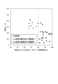
- the relationship between the area ratio of prior austenite grains with a grain size of 80 ⁇ m or less and core runout (if it is 0.25% or less, distortion in the part can be suppressed) is shown in Figure 1.
- core runout can be effectively suppressed, that is, strain in the component can be suppressed.
- prior austenite grains with a diameter of 80 ⁇ m or less are subject to regulation because prior austenite grains with a grain size larger than 80 ⁇ m have a large effect on suppressing core runout, and crystal grains with a diameter exceeding 80 ⁇ m are regulated. This is because the desired center runout suppressing ability can be obtained. Therefore, the area ratio of crystal grains with a diameter of prior austenite grains exceeding 80 ⁇ m is set to be less than 20%, in other words, the area ratio of crystal grains with a diameter of prior austenite grains of 80 ⁇ m or less is set to 80% or more.
- the prior austenite grain size can be obtained by appropriately corroding and observing the parts after high-frequency heat treatment. For example, after corroding the hardened layer formed on the surface layer of the part with a picric acid solution to reveal the prior austenite grain boundaries, the prior austenite grain structure is photographed, processed by image processing software, and the circle equivalent of each prior austenite grain is In addition to obtaining the diameter, the area ratio of crystal grains of 80 ⁇ m or less can be determined.
- the percentage of particles with a particle size that is twice or more the mode particle size is 5% or less
- the percentage of grains having a grain size twice or more the mode grain size is 5% or less
- distortion and eccentricity of the part after induction hardening can be suppressed.
- the area ratio of prior austenite grains described in the previous section is satisfied, if a certain number of prior austenite grains become significantly coarser than other grains (specifically, more than twice the grain size mode), eccentricity may be suppressed. does not reach the desired degree. Thus, it was found that the above conditions are appropriate as standards for suppressing eccentricity.
- the particle size mode can be obtained by appropriately corroding and observing the parts after high-frequency heat treatment. For example, after corroding the hardened layer formed on the surface layer of a part with a picric acid solution to reveal the prior austenite grain boundaries, the prior austenite grain structure is photographed and processed using image processing software to obtain a grain size histogram. It can be found at Furthermore, the number ratio of grains having the particle size can be determined from the histogram.
- a method of manufacturing a mechanical structural component according to the present invention will be explained. That is, a steel material having the above-mentioned composition is hot-rolled at a rolling speed that satisfies the following formula (1) to form a steel bar or wire rod, and after the steel bar or wire rod is forged into a part shape, Machine structural parts are manufactured by induction hardening at °C.
- the steel material is not particularly limited, and may include, for example, billet as a typical example, or a slab.
- the steel material for example, the slab
- the steel material must be rolled at a rolling speed that satisfies the following formula (1). It is necessary to hot-roll the steel and make it into steel bars or wire rods.
- VSL 100/DL (m/s)...(1)
- VSL is the rolling speed (m/s) just before passing through the final rolling stage
- DL is the diameter of the rolled material (mm) after rolling is completed.
- the above formula (1) is an index indicating the rolling speed when hot rolling a cast slab into a steel bar or wire rod that becomes a forging material for making machine structural parts.
- an appropriate rolling speed according to the diameter of the steel bar or wire rod, the temperature gradient inside the rolled material can be reduced and the structure of the rolled material can be controlled.
- a rolling speed that satisfies this formula it is possible to secure the time necessary for cooling the inside of the rolled material, and as a result, the temperature difference between the surface layer and the inside of the rolled material is suppressed, resulting in a homogeneous structure after rolling. I can do it. Therefore, if the rolling speed and diameter of the rolled material do not satisfy the above formula (1), the prior austenite grain size in the final part may not satisfy the above conditions even if the heat treatment conditions for the induction heat treatment described below are satisfied. Can not.
- the rolling speed it is preferable to set the rolling speed to a constant on the right side of equation (1) between 100 and 90. That is, hot rolling at a rolling speed that satisfies the following formula (2) is suitable for suppressing strain.
- VSL ⁇ 90/DL (m/s)...(2)
- VSL is the rolling speed (m/s) just before passing through the final rolling stage
- DL is the diameter of the rolled material (mm) after rolling is completed.
- the diameter of the rolled material immediately before the final stage of rolling as an indicator of rolling speed, but the final stage of rolling steel bars or wire rods usually involves slight rolling to adjust the dimensions. Since the change in diameter is minute, the diameter after rolling can be used.
- the steel bars or wire rods produced as described above are processed into parts by hot forging and/or cold forging, cutting, etc., and then subjected to high-frequency heat treatment to become parts.
- the induction hardening temperature In order for the prior austenite grains in the hardened layer after induction heat treatment to satisfy the above-mentioned grain size conditions, the induction hardening temperature must be 900 to 1150°C.
- the above temperature range is defined based on the fact that complete austenite transformation occurs during heating within the range of the component composition of the present invention, and that significant austenite grain growth does not occur during heating. Note that the tempering heat treatment after induction hardening may be performed under known conditions.
- Slabs produced by continuously casting steel having the composition shown in Table 1 were processed into billets, and then hot rolled into round bars of various diameters.
- the properties required for mechanical structural steel were investigated for the obtained round bar.
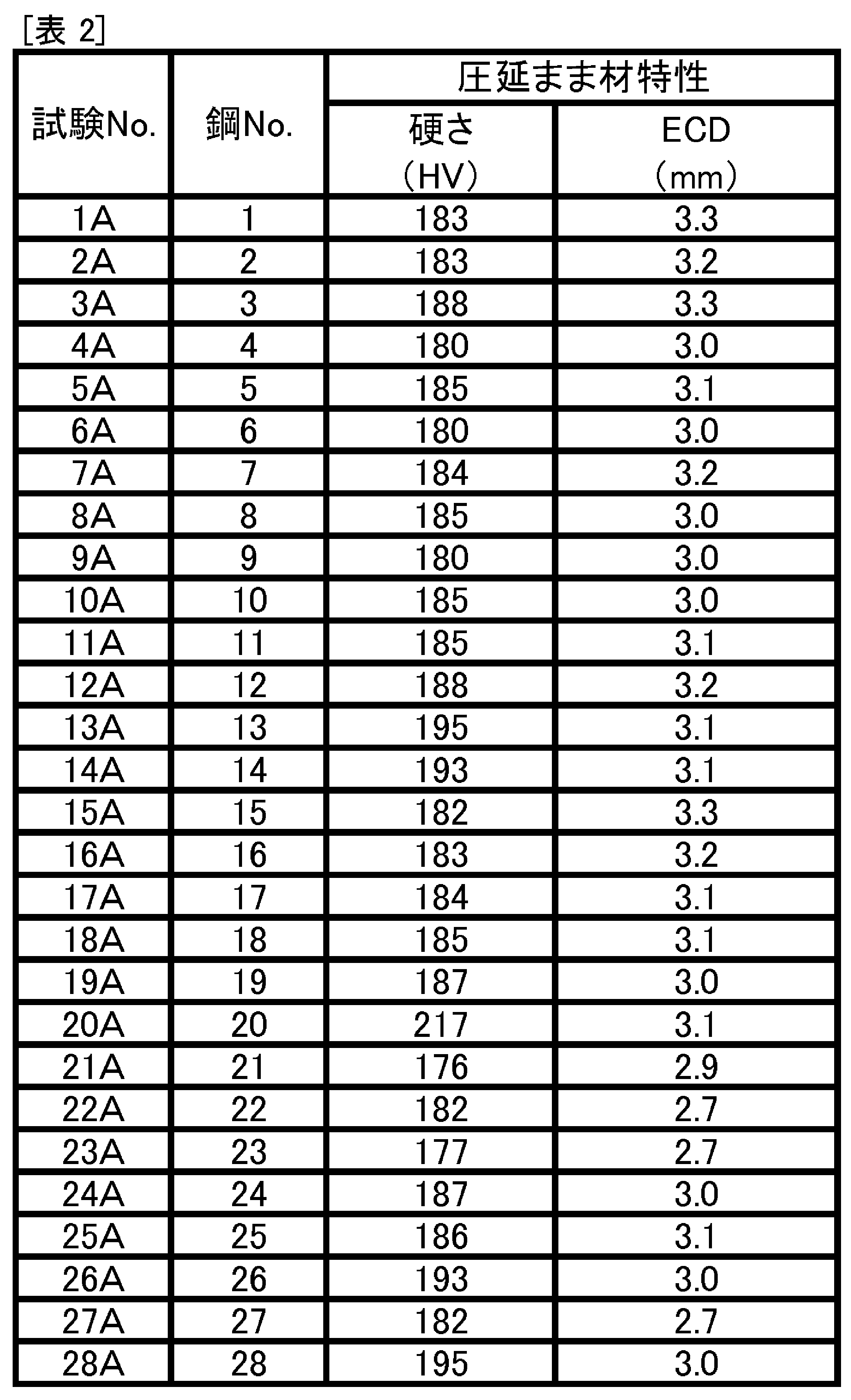
- the hardness of the round bar after hot rolling is measured as the properties required for steel for machine structural use, that is, the properties of the steel itself, and the hardness distribution is measured after the round bar is subjected to induction heat treatment as described below to evaluate hardenability. I did it.
- Vickers hardness was measured at 300 gf at a depth of 1/4 of the diameter of the round bar from the circumferential surface of the round bar. It was measured at 10 arbitrary points, and the average value was calculated and evaluated.
- the Vickers hardness here is desirably HV195 or less from the viewpoint of cold workability.
- the hardness distribution measurement after high frequency heat treatment was carried out by high frequency heat treating a round bar.
- the induction heat treatment was performed at a frequency of 8.5 kHz, a maximum heating temperature of 1000°C, and moving hardening. Tempering was carried out using a heating furnace at 180°C for 30 minutes. Thereafter, the Vickers hardness was measured at 300gf from the surface to the center on a cross section perpendicular to the axis of the round bar. That is, the first point was a depth position of 1 mm radially inward from the surface of the round bar, and thereafter measurements were made radially inward at 1 mm pitches to evaluate the radial hardness distribution.
- ECD effective hardened layer depth
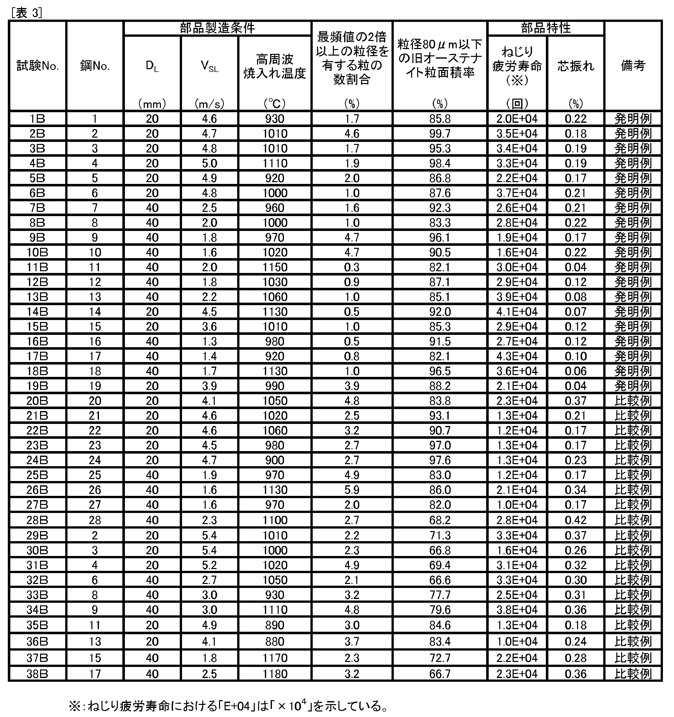
- billets made from each slab were hot rolled and induction hardened under the component manufacturing conditions shown in Table 3.
- a shaft part was fabricated using the following methods. The shape of the part is a round bar that has been extruded from a hot-rolled steel bar with an area reduction rate of 20%, and the ECD (i.e., the thickness of the hardened layer) is approximately 10% of the shaft diameter due to induction heat treatment.
- ECD i.e., the thickness of the hardened layer
- the number ratio of grains having a grain size twice or more than the mode grain size and the area ratio of crystal grains with a prior austenite grain size of 80 ⁇ m or less were investigated.
- the particle size with the largest number of particles was defined as the mode, and the ratio of particles larger than twice that number to the total number of particles was calculated. Note that when there are multiple candidates for the mode, the smallest one among them was treated as the mode.
- Torsional fatigue life Torsional fatigue life was measured using an electric servo type torsional fatigue testing machine. Loading was carried out at 2 Hz so that the maximum shear stress was 300 MPa, and the number of repetitions until failure was measured. If it shows a fracture life of 15,000 cycles or more in this test, it can be said that it has sufficient fatigue strength.
- FIG. 1 summarizes the relationship between the area ratio of prior austenite grains with a grain size of 80 ⁇ m or less and core runout. Note that the figure shows only examples whose fatigue life is within the preferred range.
Landscapes
- Chemical & Material Sciences (AREA)
- Engineering & Computer Science (AREA)
- Materials Engineering (AREA)
- Mechanical Engineering (AREA)
- Metallurgy (AREA)
- Organic Chemistry (AREA)
- Physics & Mathematics (AREA)
- Thermal Sciences (AREA)
- Crystallography & Structural Chemistry (AREA)
- Manufacturing & Machinery (AREA)
- Heat Treatment Of Steel (AREA)
- Heat Treatment Of Articles (AREA)
Abstract
Description
(a)高周波熱処理後の硬化層における旧オーステナイト粒径のばらつきを小さくする。(b)高周波熱処理後の硬化層において、粒径の小さい旧オーステナイト粒が多くの面積を占めるようにする。
1.質量%で
C:0.45~0.51%、
Si:0.15~0.35%、
Mn:0.60~0.90%、
P:0.030%以下、
S:0.025%以下、
Al:0.040~0.059%、
Cr:0.10~0.50%および
N:0.0060~0.0100%
を含み、残部はFe及び不純物の成分組成を有し、高周波焼入れ・焼戻し処理による硬化層を有する部品であって、前記硬化層における旧オーステナイト粒の径が80μm以下の結晶粒の面積率が80%以上であり、かつ前記硬化層における粒径最頻値の2倍以上の粒径を有する粒の数割合が5%以下である機械構造部品。
C:0.45~0.51%、
Si:0.15~0.35%、
Mn:0.60~0.90%、
P:0.030%以下、
S:0.025%以下、
Al:0.040~0.059%、
Cr:0.10~0.50%および
N:0.0060~0.0100%
を含み、残部はFe及び不純物の成分組成からなる鋼素材に、下記式(1)を満足する圧延速度VSLにて熱間圧延を施して棒鋼または線材とし、該棒鋼または線材を鍛造成形した後に900~1150℃にて高周波焼入れを施して焼戻しを行う、機械構造部品の製造方法。
記
VSL≦100/DL (m/s)・・・(1)
ただし、VSLは圧延最終段通過直前の圧延速度(m/s)、DLは圧延完了後の圧延材直径(mm)。
C:0.45~0.51%
Cは、高周波熱処理を施した際の部品の硬化層強度を確保するために必須となる元素である。C含有量が0.45%未満の場合は、部品としての強度が不十分となる。一方でC含有量が0.51%を超えると、高周波熱処理後のひずみ量が増加する。以上の理由により、C含有量は0.45~0.51%の範囲と定める。強度とひずみ量とをバランスさせる観点からは、C含有量を0.47%以上とすることが望ましい。同様に、0.49%以下とすることが望ましい。
Siは、鋼の脱酸作用による酸素系介在物の低減と焼戻し熱処理における硬さ低下抑制の作用を有する。すなわち、製品としての機械的特性を向上させる効果を有する。一方で過剰に添加すると、素材が硬化することにより冷間加工性が低下してしまう。以上の理由により、Si含有量は0.15~0.35%の範囲と定める。より望ましい範囲としては、0.20%以上である。より望ましい範囲としては、0.30%以下である。
Mnは、焼入れ性を大きく向上させる作用があり、そのためには0.60%以上の添加が必要である。一方で添加量が増加するに伴い素材硬さの増加ならびに冷間加工性の低下が生じるが、0.90%までは許容される。以上の理由によりMn含有量は0.60~0.90%の範囲と定める。なお、より望ましい範囲としては0.70%以上である。より望ましい範囲としては、0.80%以下である。
Pは、高周波焼入れ後の旧オーステナイト粒界に偏析し、硬化層の疲労特性を低下させる作用を有する。そのためP含有量は可能な限り少量に抑えることが好ましい。以上の理由によりP含有量を0.030%以下の範囲と定める。なお、より好ましくは0.012%以下に抑制するのが良い。0%であっても良いのは、勿論である。
Sは、硫黄系介在物として存在し、被削性の向上に有効な元素であるが、0.025%を超える添加は鋳造時の製造性に悪影響を及ぼすため、上限量は0.025%とする。なお、被削性の向上が必要な場合は0.010%以上添加してもよく、0.010~0.015%の範囲が好適である。なお、被削性を考慮する必要がない場合は、0%であっても良い。
Alは、Nと結合してAlNを形成するため、棒鋼・線材の圧延時ならびに高周波焼入れ時のオーステナイト粒の粗大化を抑制する作用を持つ。棒鋼・線材の圧延および高周波焼入れ時のオーステナイト粒径制御がひずみ抑制において効果的であるため、本発明において重要な元素である。Al含有量が少ない場合には、上記効果が見込まれない。一方でAl含有量が過剰である場合は、介在物の増加を招いて疲労破壊の起点を増やし、疲労強度低下の原因となる。以上の理由により、Al含有量を0.040~0.059%の範囲と定めた。好ましくは、0.045%以上である。好ましくは、0.055%以下である。
Crは、焼入れ性の向上や鋼の強度改善に有効に作用する。一方でCr含有量が多くなると、硬さ増加による加工性の低下が避けられない。以上の理由により、Cr含有量を0.10~0.50%の範囲と定めた。好ましくは、0.10%以上である。好ましくは、0.20%以下である。
Nは、Alと結合してAlNを形成するため、Alと同様、本発明において重要な元素である。Nを0.0060%以上含有させることが、棒線・線材圧延および高周波焼入れ時のオーステナイト粒径制御に必要である。一方でN含有量が多くなると、凝固時に割れが発生し、その後の工程においても疵として残存することになる。この疵が残ったままでは、疵が開いて割れが著しく発生しやすくなるため、製品として使用できなくなる。以上の理由により、N含有量を0.0060~0.0100%の範囲と定めた。好ましくは、0.0060%以上である。好ましくは、0.0080%以下である。
本発明の機械構造部品は、上述した成分組成の鋼を用いて、例えば軸部を有する形状などの部品形状に成形され、その後に高周波焼入れ・焼戻しの高周波熱処理が施される。この高周波熱処理により形成される硬化層において、旧オーステナイト粒の径が80μm以下の結晶粒の面積率が80%以上であり、かつ粒径最頻値の2倍以上の粒径を有する粒の数割合が5%以下である必要がある。
本発明の機械構造部品では、部品形状となった成形体に高周波焼入れ・焼戻しの高周波熱処理を施して表層に硬化層を形成する。この硬化層は、高周波熱処理によって硬化した部分である。具体的には、高周波熱処理後の部品表面から中心に向かう硬さ(例えばビッカース硬さ)分布測定を行って、得られた硬さ分布において所定の硬さ(例えばHV450)が維持されている深さ位置までを有効硬化層深さ(ECD)として、この有効硬化層深さの領域を硬化層とする。
この旧オーステナイト粒径の規定は、高周波熱処理後のひずみを抑制可能な旧オーステナイト粒の性状を示す指標である。ここで、後述の実施例における、粒径80μm以下の旧オーステナイト粒の面積率と芯振れ(0.25%以下であれば、部品におけるひずみの抑制が実現)との関係を図1に示すように、旧オーステナイト粒の径が80μm以下の結晶粒の面積率が80%以上を満足するとき、芯振れを効果的に抑制、すなわち部品におけるひずみを抑制することができる。なお、旧オーステナイト粒の径が80μm以下の結晶粒を規制対象とするのは、粒径80μmよりも大きい旧オーステナイト粒は、芯振れ抑制に与える影響が大きく、80μm超の結晶粒を規制することによって、所望の芯振れ抑制能が得られるからである。そのため、旧オーステナイト粒の径が80μm超の結晶粒の面積率は20%未満とすること、言い換えると、旧オーステナイト粒の径が80μm以下の結晶粒の面積率を80%以上とする。
硬化層において、粒径最頻値の2倍以上の粒径を有する粒の数割合を5%以下にすることによって、高周波焼入れ後の部品のひずみ並びに偏心を抑制することができる。前項の旧オーステナイト粒の面積率を満足する場合においても、一定少数の旧オーステナイト粒が他の粒よりも著しく粗大化(具体的には粒径最頻値の2倍以上)すると、偏心の抑制が所望の程度まで達しない。かように、偏心の抑制の基準として、上記条件が適切であることを知見した。
すなわち、上記した成分組成を有する鋼素材に、下記式(1)を満足する圧延速度にて熱間圧延を施して棒鋼又は線材とし、該棒鋼または線材を部品形状に鍛造成形した後に900~1150℃にて高周波焼入れを施して、機械構造部品を製造する。なお、鋼素材としては、例えばビレットを典型例とする鋳片やスラブ等、特に限定されない。
記
VSL≦100/DL (m/s)・・・(1)
ただし、VSLは圧延最終段通過直前の圧延速度(m/s)、DLは圧延完了後の圧延材直径(mm)。
記
VSL≦90/DL (m/s)・・・(2)
ただし、VSLは圧延最終段通過直前の圧延速度(m/s)、DLは圧延完了後の圧延材直径(mm)。

これらの測定結果を表2に示す。
部品の硬化層における旧オーステナイト粒の観察は、上記軸部品の軸垂直断面を観察面とするサンプルを切り出し実施した。切り出したサンプルを3%ピクリン酸水溶液にて腐食し、光学顕微鏡を用いてECDの半分の位置において旧オーステナイト粒組織を200倍にて10視野撮影した。その撮影写真を基に、旧オーステナイト粒界をトレースし、トレース像を画像処理ソフトウェアのImageJにより処理し、各旧オーステナイト粒における直径を円相当径として整数となるように四捨五入し算出した。得られた粒径データから、最も粒の数が多い粒径を最頻値として定義し、その2倍よりも大きい粒の全粒数に対する個数割合を算出した。なお、最頻値の候補が複数ある場合は、その中で最小のものを最頻値として取り扱った。
上記と同様に得た、トレース像を画像解析することによって、粒径80μm以下の旧オーステナイト粒の面積率を算出した。
[ねじり疲労寿命]
ねじり疲労寿命は、電気サーボ式ねじり疲労試験機を用いて実施した。負荷は2Hzにて、最大せん断応力が300MPaとなるように実施し、破壊までの繰返し数を測定した。本試験において15,000回以上の破壊寿命を示す場合、十分な疲労強度を有しているといえる。
部品のひずみを、偏心検査機によって測定した。すなわち、高周波熱処理前に両端部中心にあけた穴を支持することにより部品を一周させたときの変位の変化幅(変位最大値と変位最小値の差)を測定部分の直径で除することにより芯振れ(%)を算出した。今回の試験においては芯振れが0.25%以下であれば、部品としてのひずみが十分抑制されているといえる。
Claims (3)
- 質量%で
C:0.45~0.51%、
Si:0.15~0.35%、
Mn:0.60~0.90%、
P:0.030%以下、
S:0.025%以下、
Al:0.040~0.059%、
Cr:0.10~0.50%および
N:0.0060~0.0100%
を含み、残部はFe及び不純物の成分組成を有し、高周波焼入れ・焼戻し処理による硬化層を有する部品であって、前記硬化層における旧オーステナイト粒の径が80μm以下の結晶粒の面積率が80%以上であり、かつ前記硬化層における粒径最頻値の2倍以上の粒径を有する粒の数割合が5%以下である機械構造部品。 - 前記部品が軸形状部を有する部品である、請求項1に記載の機械構造部品。
- 質量%で
C:0.45~0.51%、
Si:0.15~0.35%、
Mn:0.60~0.90%、
P:0.030%以下、
S:0.025%以下、
Al:0.040~0.059%、
Cr:0.10~0.50%および
N:0.0060~0.0100%
を含み、残部はFe及び不純物の成分組成からなる鋼素材に、下記式(1)を満足する圧延速度VSLにて熱間圧延を施して棒鋼または線材とし、該棒鋼または線材を鍛造成形した後に900~1150℃にて高周波焼入れを施して焼戻しを行う、機械構造部品の製造方法。
記
VSL≦100/DL (m/s)・・・(1)
ただし、VSLは圧延最終段通過直前の圧延速度(m/s)、DLは圧延完了後の圧延材直径(mm)。
Priority Applications (6)
| Application Number | Priority Date | Filing Date | Title |
|---|---|---|---|
| US18/845,139 US20250179599A1 (en) | 2022-03-31 | 2023-03-27 | Mechanical structural part and method for manufacturing same |
| KR1020247031166A KR20240152368A (ko) | 2022-03-31 | 2023-03-27 | 기계 구조 부품 및 그 제조 방법 |
| JP2023542018A JP7420321B1 (ja) | 2022-03-31 | 2023-03-27 | 機械構造部品およびその製造方法 |
| EP23780418.2A EP4474513A4 (en) | 2022-03-31 | 2023-03-27 | MECHANICAL STRUCTURAL PART AND ITS MANUFACTURING PROCESS |
| CN202380030357.1A CN119213155A (zh) | 2022-03-31 | 2023-03-27 | 机械结构部件及其制造方法 |
| MX2024011893A MX2024011893A (es) | 2022-03-31 | 2024-09-26 | Parte estructural mecanica y metodo para fabricar la misma |
Applications Claiming Priority (2)
| Application Number | Priority Date | Filing Date | Title |
|---|---|---|---|
| JP2022061367 | 2022-03-31 | ||
| JP2022-061367 | 2022-03-31 |
Publications (1)
| Publication Number | Publication Date |
|---|---|
| WO2023190409A1 true WO2023190409A1 (ja) | 2023-10-05 |
Family
ID=88202385
Family Applications (1)
| Application Number | Title | Priority Date | Filing Date |
|---|---|---|---|
| PCT/JP2023/012333 Ceased WO2023190409A1 (ja) | 2022-03-31 | 2023-03-27 | 機械構造部品およびその製造方法 |
Country Status (7)
| Country | Link |
|---|---|
| US (1) | US20250179599A1 (ja) |
| EP (1) | EP4474513A4 (ja) |
| JP (1) | JP7420321B1 (ja) |
| KR (1) | KR20240152368A (ja) |
| CN (1) | CN119213155A (ja) |
| MX (1) | MX2024011893A (ja) |
| WO (1) | WO2023190409A1 (ja) |
Citations (6)
| Publication number | Priority date | Publication date | Assignee | Title |
|---|---|---|---|---|
| JP2004204263A (ja) | 2002-12-24 | 2004-07-22 | Nippon Steel Corp | 冷間加工性と浸炭時の粗大粒防止特性に優れた肌焼用鋼材とその製造方法 |
| JP2006265703A (ja) | 2005-03-25 | 2006-10-05 | Kobe Steel Ltd | 耐結晶粒粗大化特性と冷間加工性に優れた肌焼用鋼およびその製法 |
| JP2008133530A (ja) * | 2006-10-31 | 2008-06-12 | Jfe Steel Kk | 軸受鋼部品およびその製造方法並びに軸受 |
| JP2010236062A (ja) * | 2009-03-31 | 2010-10-21 | Jfe Steel Corp | 機械構造用部品の製造方法 |
| WO2011049006A1 (ja) * | 2009-10-22 | 2011-04-28 | 新日本製鐵株式会社 | 高周波焼入れ用鋼及び高周波焼入れ鋼部品、並びに、それらの製造方法 |
| JP2013151719A (ja) | 2012-01-25 | 2013-08-08 | Nippon Steel & Sumitomo Metal Corp | 熱間鍛造用圧延棒鋼または線材 |
Family Cites Families (7)
| Publication number | Priority date | Publication date | Assignee | Title |
|---|---|---|---|---|
| JPH0660345B2 (ja) | 1985-05-13 | 1994-08-10 | 株式会社神戸製鋼所 | 冷間加工性にすぐれ,且つ,浸炭加熱時の結晶粒粗大化を防止した鋼の製造方法 |
| JP3870425B2 (ja) | 1995-01-20 | 2007-01-17 | 大同特殊鋼株式会社 | 結晶粒の異常成長を防止した冷間加工用肌焼鋼の 製造方法 |
| US7678207B2 (en) * | 2003-01-17 | 2010-03-16 | Jfe Steel Corporation | Steel product for induction hardening, induction-hardened member using the same, and methods producing them |
| DE602004032363D1 (de) * | 2003-09-29 | 2011-06-01 | Jfe Steel Corp | Stahlprodukt für das induktionshärten, induktionsgehärtetes bauelement, bei dem dieses verwendet wird, und herstellungsverfahren dafür |
| JP4581966B2 (ja) * | 2005-11-08 | 2010-11-17 | 住友金属工業株式会社 | 高周波焼入れ用鋼材 |
| JP4828321B2 (ja) * | 2006-06-16 | 2011-11-30 | 新日本製鐵株式会社 | 低サイクル疲労特性に優れた高周波焼入れ鋼材及び高周波焼入れ部品 |
| JP5505264B2 (ja) * | 2010-11-05 | 2014-05-28 | 新日鐵住金株式会社 | 低サイクル疲労特性に優れた高周波輪郭焼入れ鋼材及び高周波輪郭焼入れ部品 |
-
2023
- 2023-03-27 WO PCT/JP2023/012333 patent/WO2023190409A1/ja not_active Ceased
- 2023-03-27 EP EP23780418.2A patent/EP4474513A4/en active Pending
- 2023-03-27 KR KR1020247031166A patent/KR20240152368A/ko active Pending
- 2023-03-27 US US18/845,139 patent/US20250179599A1/en active Pending
- 2023-03-27 CN CN202380030357.1A patent/CN119213155A/zh active Pending
- 2023-03-27 JP JP2023542018A patent/JP7420321B1/ja active Active
-
2024
- 2024-09-26 MX MX2024011893A patent/MX2024011893A/es unknown
Patent Citations (6)
| Publication number | Priority date | Publication date | Assignee | Title |
|---|---|---|---|---|
| JP2004204263A (ja) | 2002-12-24 | 2004-07-22 | Nippon Steel Corp | 冷間加工性と浸炭時の粗大粒防止特性に優れた肌焼用鋼材とその製造方法 |
| JP2006265703A (ja) | 2005-03-25 | 2006-10-05 | Kobe Steel Ltd | 耐結晶粒粗大化特性と冷間加工性に優れた肌焼用鋼およびその製法 |
| JP2008133530A (ja) * | 2006-10-31 | 2008-06-12 | Jfe Steel Kk | 軸受鋼部品およびその製造方法並びに軸受 |
| JP2010236062A (ja) * | 2009-03-31 | 2010-10-21 | Jfe Steel Corp | 機械構造用部品の製造方法 |
| WO2011049006A1 (ja) * | 2009-10-22 | 2011-04-28 | 新日本製鐵株式会社 | 高周波焼入れ用鋼及び高周波焼入れ鋼部品、並びに、それらの製造方法 |
| JP2013151719A (ja) | 2012-01-25 | 2013-08-08 | Nippon Steel & Sumitomo Metal Corp | 熱間鍛造用圧延棒鋼または線材 |
Non-Patent Citations (1)
| Title |
|---|
| See also references of EP4474513A4 |
Also Published As
| Publication number | Publication date |
|---|---|
| JPWO2023190409A1 (ja) | 2023-10-05 |
| EP4474513A1 (en) | 2024-12-11 |
| KR20240152368A (ko) | 2024-10-21 |
| EP4474513A4 (en) | 2026-03-18 |
| JP7420321B1 (ja) | 2024-01-23 |
| US20250179599A1 (en) | 2025-06-05 |
| MX2024011893A (es) | 2024-11-08 |
| CN119213155A (zh) | 2024-12-27 |
Similar Documents
| Publication | Publication Date | Title |
|---|---|---|
| WO2013094475A1 (ja) | 冷間加工用機械構造用鋼およびその製造方法 | |
| JP6109729B2 (ja) | 浸炭処理時の結晶粒粗大化防止特性に優れた肌焼鋼 | |
| WO2012005373A1 (ja) | 高強度ばね用伸線熱処理鋼線および高強度ばね用伸線前鋼線 | |
| JP2001240940A (ja) | 冷間鍛造用棒線材とその製造方法 | |
| CN107923011A (zh) | 冷加工用机械结构用钢及其制造方法 | |
| JP2002226939A (ja) | 軟窒化用非調質鋼 | |
| WO2016158343A1 (ja) | 冷間圧造性、および焼入れ焼戻し後の耐遅れ破壊性に優れたボルト用鋼線、並びにボルト | |
| JP4632931B2 (ja) | 冷間加工性に優れる高周波焼入れ用鋼及びその製造方法 | |
| JP2000265240A (ja) | 精密打抜き性に優れた炭素鋼板 | |
| WO2013031587A1 (ja) | 熱間鍛造用圧延棒鋼又は線材 | |
| JP5990428B2 (ja) | 転動疲労特性に優れた軸受用鋼材およびその製造方法 | |
| JP6969683B2 (ja) | 高周波焼入れクランクシャフト及び高周波焼入れクランクシャフト用素形材の製造方法 | |
| JP7140274B2 (ja) | 鋼軸部品 | |
| JP2001342544A (ja) | 室温及び加工発熱領域の変形抵抗の上昇が抑制された線状または棒状鋼、および機械部品 | |
| JP7420321B1 (ja) | 機械構造部品およびその製造方法 | |
| JP4983099B2 (ja) | 衝撃特性と疲労特性に優れた鋼軸部品とその製造方法 | |
| JP5365477B2 (ja) | 表面硬化処理用鋼材 | |
| JP7716332B2 (ja) | 機械構造部品用鋼線およびその製造方法 | |
| CN1307319C (zh) | 滚轧成形性、耐淬裂性及扭转特性优异的机械结构用钢材以及传动轴 | |
| JP3242336B2 (ja) | 冷間鍛造性および疲労強度に優れた冷間鍛造用鋼ならびに冷間鍛造部材の製造方法 | |
| JP7782477B2 (ja) | 軸受用鋼 | |
| US12595527B2 (en) | Steel wire for machine structural parts and method for manufacturing the same | |
| JP2020100861A (ja) | 静捩り強度ならびに捩り疲労強度に優れた高周波焼入れ用鋼材による自動車用機械部品 | |
| JPH04297552A (ja) | 等速ジョイント部品の製造方法 | |
| JPH11106866A (ja) | 粗大粒防止特性に優れた肌焼鋼とその製造方法 |
Legal Events
| Date | Code | Title | Description |
|---|---|---|---|
| WWE | Wipo information: entry into national phase |
Ref document number: 2023542018 Country of ref document: JP |
|
| 121 | Ep: the epo has been informed by wipo that ep was designated in this application |
Ref document number: 23780418 Country of ref document: EP Kind code of ref document: A1 |
|
| WWE | Wipo information: entry into national phase |
Ref document number: 202417065272 Country of ref document: IN |
|
| WWE | Wipo information: entry into national phase |
Ref document number: 2023780418 Country of ref document: EP |
|
| WWE | Wipo information: entry into national phase |
Ref document number: 18845139 Country of ref document: US |
|
| ENP | Entry into the national phase |
Ref document number: 2023780418 Country of ref document: EP Effective date: 20240906 |
|
| ENP | Entry into the national phase |
Ref document number: 20247031166 Country of ref document: KR Kind code of ref document: A |
|
| WWE | Wipo information: entry into national phase |
Ref document number: 1020247031166 Country of ref document: KR |
|
| WWE | Wipo information: entry into national phase |
Ref document number: 202380030357.1 Country of ref document: CN |
|
| WWE | Wipo information: entry into national phase |
Ref document number: MX/A/2024/011893 Country of ref document: MX Ref document number: 2401006357 Country of ref document: TH |
|
| NENP | Non-entry into the national phase |
Ref country code: DE |
|
| WWP | Wipo information: published in national office |
Ref document number: 202380030357.1 Country of ref document: CN |
|
| WWP | Wipo information: published in national office |
Ref document number: 18845139 Country of ref document: US |