WO2023190889A1 - Climatiseur - Google Patents
Climatiseur Download PDFInfo
- Publication number
- WO2023190889A1 WO2023190889A1 PCT/JP2023/013216 JP2023013216W WO2023190889A1 WO 2023190889 A1 WO2023190889 A1 WO 2023190889A1 JP 2023013216 W JP2023013216 W JP 2023013216W WO 2023190889 A1 WO2023190889 A1 WO 2023190889A1
- Authority
- WO
- WIPO (PCT)
- Prior art keywords
- heat exchanger
- fin
- exchanger tube
- air conditioner
- fins
- Prior art date
- Legal status (The legal status is an assumption and is not a legal conclusion. Google has not performed a legal analysis and makes no representation as to the accuracy of the status listed.)
- Ceased
Links
Images


Classifications
-
- F—MECHANICAL ENGINEERING; LIGHTING; HEATING; WEAPONS; BLASTING
- F28—HEAT EXCHANGE IN GENERAL
- F28F—DETAILS OF HEAT-EXCHANGE AND HEAT-TRANSFER APPARATUS, OF GENERAL APPLICATION
- F28F1/00—Tubular elements; Assemblies of tubular elements
- F28F1/10—Tubular elements and assemblies thereof with means for increasing heat-transfer area, e.g. with fins, with projections, with recesses
-
- F—MECHANICAL ENGINEERING; LIGHTING; HEATING; WEAPONS; BLASTING
- F25—REFRIGERATION OR COOLING; COMBINED HEATING AND REFRIGERATION SYSTEMS; HEAT PUMP SYSTEMS; MANUFACTURE OR STORAGE OF ICE; LIQUEFACTION SOLIDIFICATION OF GASES
- F25B—REFRIGERATION MACHINES, PLANTS OR SYSTEMS; COMBINED HEATING AND REFRIGERATION SYSTEMS; HEAT PUMP SYSTEMS
- F25B39/00—Evaporators; Condensers
- F25B39/02—Evaporators
-
- F—MECHANICAL ENGINEERING; LIGHTING; HEATING; WEAPONS; BLASTING
- F24—HEATING; RANGES; VENTILATING
- F24F—AIR-CONDITIONING; AIR-HUMIDIFICATION; VENTILATION; USE OF AIR CURRENTS FOR SCREENING
- F24F1/00—Room units for air-conditioning, e.g. separate or self-contained units or units receiving primary air from a central station
- F24F1/0003—Room units for air-conditioning, e.g. separate or self-contained units or units receiving primary air from a central station characterised by a split arrangement, wherein parts of the air-conditioning system, e.g. evaporator and condenser, are in separately located units
-
- F—MECHANICAL ENGINEERING; LIGHTING; HEATING; WEAPONS; BLASTING
- F24—HEATING; RANGES; VENTILATING
- F24F—AIR-CONDITIONING; AIR-HUMIDIFICATION; VENTILATION; USE OF AIR CURRENTS FOR SCREENING
- F24F13/00—Details common to, or for air-conditioning, air-humidification, ventilation or use of air currents for screening
- F24F13/22—Means for preventing condensation or evacuating condensate
-
- F—MECHANICAL ENGINEERING; LIGHTING; HEATING; WEAPONS; BLASTING
- F24—HEATING; RANGES; VENTILATING
- F24F—AIR-CONDITIONING; AIR-HUMIDIFICATION; VENTILATION; USE OF AIR CURRENTS FOR SCREENING
- F24F13/00—Details common to, or for air-conditioning, air-humidification, ventilation or use of air currents for screening
- F24F13/30—Arrangement or mounting of heat-exchangers
-
- F—MECHANICAL ENGINEERING; LIGHTING; HEATING; WEAPONS; BLASTING
- F25—REFRIGERATION OR COOLING; COMBINED HEATING AND REFRIGERATION SYSTEMS; HEAT PUMP SYSTEMS; MANUFACTURE OR STORAGE OF ICE; LIQUEFACTION SOLIDIFICATION OF GASES
- F25B—REFRIGERATION MACHINES, PLANTS OR SYSTEMS; COMBINED HEATING AND REFRIGERATION SYSTEMS; HEAT PUMP SYSTEMS
- F25B39/00—Evaporators; Condensers
- F25B39/04—Condensers
-
- F—MECHANICAL ENGINEERING; LIGHTING; HEATING; WEAPONS; BLASTING
- F28—HEAT EXCHANGE IN GENERAL
- F28D—HEAT-EXCHANGE APPARATUS, NOT PROVIDED FOR IN ANOTHER SUBCLASS, IN WHICH THE HEAT-EXCHANGE MEDIA DO NOT COME INTO DIRECT CONTACT
- F28D1/00—Heat-exchange apparatus having stationary conduit assemblies for one heat-exchange medium only, the media being in contact with different sides of the conduit wall, in which the other heat-exchange medium is a large body of fluid, e.g. domestic or motor car radiators
- F28D1/02—Heat-exchange apparatus having stationary conduit assemblies for one heat-exchange medium only, the media being in contact with different sides of the conduit wall, in which the other heat-exchange medium is a large body of fluid, e.g. domestic or motor car radiators with heat-exchange conduits immersed in the body of fluid
- F28D1/04—Heat-exchange apparatus having stationary conduit assemblies for one heat-exchange medium only, the media being in contact with different sides of the conduit wall, in which the other heat-exchange medium is a large body of fluid, e.g. domestic or motor car radiators with heat-exchange conduits immersed in the body of fluid with tubular conduits
- F28D1/053—Heat-exchange apparatus having stationary conduit assemblies for one heat-exchange medium only, the media being in contact with different sides of the conduit wall, in which the other heat-exchange medium is a large body of fluid, e.g. domestic or motor car radiators with heat-exchange conduits immersed in the body of fluid with tubular conduits the conduits being straight
-
- F—MECHANICAL ENGINEERING; LIGHTING; HEATING; WEAPONS; BLASTING
- F28—HEAT EXCHANGE IN GENERAL
- F28F—DETAILS OF HEAT-EXCHANGE AND HEAT-TRANSFER APPARATUS, OF GENERAL APPLICATION
- F28F1/00—Tubular elements; Assemblies of tubular elements
- F28F1/10—Tubular elements and assemblies thereof with means for increasing heat-transfer area, e.g. with fins, with projections, with recesses
- F28F1/12—Tubular elements and assemblies thereof with means for increasing heat-transfer area, e.g. with fins, with projections, with recesses the means being only outside the tubular element
- F28F1/24—Tubular elements and assemblies thereof with means for increasing heat-transfer area, e.g. with fins, with projections, with recesses the means being only outside the tubular element and extending transversely
- F28F1/32—Tubular elements and assemblies thereof with means for increasing heat-transfer area, e.g. with fins, with projections, with recesses the means being only outside the tubular element and extending transversely the means having portions engaging further tubular elements
- F28F1/325—Fins with openings
-
- F—MECHANICAL ENGINEERING; LIGHTING; HEATING; WEAPONS; BLASTING
- F28—HEAT EXCHANGE IN GENERAL
- F28F—DETAILS OF HEAT-EXCHANGE AND HEAT-TRANSFER APPARATUS, OF GENERAL APPLICATION
- F28F2215/00—Fins
- F28F2215/04—Assemblies of fins having different features, e.g. with different fin densities
-
- F—MECHANICAL ENGINEERING; LIGHTING; HEATING; WEAPONS; BLASTING
- F28—HEAT EXCHANGE IN GENERAL
- F28F—DETAILS OF HEAT-EXCHANGE AND HEAT-TRANSFER APPARATUS, OF GENERAL APPLICATION
- F28F2225/00—Reinforcing means
- F28F2225/06—Reinforcing means for fins
Definitions
- Patent Document 1 Japanese Unexamined Patent Application Publication No. 2001-304783
- an air system configured by connecting an indoor unit including an indoor heat exchanger and an outdoor unit including an outdoor heat exchanger.
- a harmonizer is known.
- the indoor heat exchanger and outdoor heat exchanger of Patent Document 1 are formed by having a plurality of fins pass through a heat transfer tube.
- the air conditioner according to the first aspect includes an outdoor unit and an indoor unit.
- the outdoor unit includes a first heat exchanger.
- the first heat exchanger includes a first heat exchanger tube and a plurality of first fins.
- the first heat exchanger tube is made of aluminum or aluminum alloy.
- the plurality of first fins are made of aluminum or aluminum alloy.
- the indoor unit includes a second heat exchanger.
- the second heat exchanger includes a second heat exchanger tube and a plurality of second fins.
- the second heat exchanger tube is made of aluminum or aluminum alloy.
- the plurality of second fins are made of aluminum or aluminum alloy.
- a first sacrificial layer is provided on the surface of the first heat exchanger tube.
- the first sacrificial layer has a lower potential than the base material of the first heat exchanger tube, and has a lower potential than the first fin.
- the fin pitch of the first fin is larger than the fin pitch of the second fin.
- the first heat exchanger tube made of aluminum or aluminum alloy is provided with the first sacrificial layer that is less noble in potential than the base material, thereby suppressing corrosion of the base material.
- the first sacrificial layer has a lower potential than the first fin made of aluminum or an aluminum alloy, the first sacrificial layer may be corroded by the first fin.
- the fin of the first fin of the first heat exchanger is made larger than the fin pitch of the second fins of the second heat exchanger. Therefore, the surface area of the first fins that come into contact with the first sacrificial layer of the first heat exchanger tube can be reduced. Therefore, corrosion of the first sacrificial layer can be suppressed.
- the air conditioner according to the second aspect is the air conditioner according to the first aspect, and the first heat exchanger tube and the second heat exchanger tube have a cylindrical shape.
- the air conditioner of the present disclosure is suitable for an air conditioner including a first heat exchanger having a cylindrical first heat exchanger tube and a second heat exchanger having a cylindrical second heat exchanger tube. used for.
- the air conditioner according to the third aspect is the air conditioner according to the first aspect or the second aspect, in which a first surface layer containing resin is provided on the surface of the first fin.
- the corrosion rate of the first sacrificial layer can be slowed down by the electrical resistance between the first surface layer containing resin and the first heat exchanger tube.
- the air conditioner according to the fourth aspect is the air conditioner according to the third aspect, in which a second surface layer containing resin is provided on the surface of the second fin.
- the thickness of the first surface layer is greater than the thickness of the second surface layer.
- the electrical resistance between the first surface layer of the outdoor unit and the first heat exchanger tube which is susceptible to salt damage, is determined from the electrical resistance between the second surface layer of the indoor unit and the second heat exchanger tube. can also be made larger. Therefore, the corrosion rate of the first sacrificial layer can be further reduced.
- the air conditioner according to the fifth aspect is any of the air conditioners according to the first to fourth aspects, and a second sacrificial layer is provided on the surface of the second heat exchanger tube.
- the second sacrificial layer has a lower potential than the base material of the second heat exchanger tube, and has a lower potential than the second fin.
- the second heat exchanger tube made of aluminum or aluminum alloy is provided with the second sacrificial layer that is more base in potential than the base material, corrosion of the base material can be suppressed. Further, since the second sacrificial layer has a lower potential than the second fin, it is possible to suppress a decrease in workability of the second fin.
- the air conditioner according to the sixth aspect is any one of the first to fifth aspects, in which the difference between the fin pitch of the first fin and the fin pitch of the second fin is 0. It is 1 mm or more and 0.3 mm or less.
- corrosion of the first sacrificial layer can be further suppressed by setting the pitch difference to 0.1 mm or more and 0.3 mm or less.
- the air conditioner according to the seventh aspect is any of the air conditioners according to the first to sixth aspects, wherein the fin pitch of the first fin is more than 1.0 times the fin pitch of the second fin. It is less than 1.3 times.
- the ratio of the fin pitch of the first fin to the fin pitch of the second fin is greater than 1.0 and less than 1.3. By doing so, corrosion of the first sacrificial layer can be further suppressed.
- the air conditioner according to the eighth aspect is any of the air conditioners according to the first to seventh aspects, and a second sacrificial layer is provided on the surface of the second heat exchanger tube.
- the second sacrificial layer has a lower potential than the base material of the second heat exchanger tube.
- the thickness of the first sacrificial layer and the thickness of the second sacrificial layer are the same.
- the production efficiency of the first heat exchanger and the second heat exchanger can be improved. can be improved.
- the air conditioner according to the ninth aspect is any one of the first to eighth aspects, in which the outer diameter of the first heat exchanger tube and the outer diameter of the second heat exchanger tube are the same. be.
- the outer diameter of the first heat exchanger tube and the outer diameter of the second heat exchanger tube can be made common, the production efficiency of the first heat exchanger and the second heat exchanger can be improved. can.
- the air conditioner according to the tenth aspect is any of the air conditioners according to the first to ninth aspects, and the material of the first heat exchanger tube and the material of the second heat exchanger tube are the same.
- the material of the first heat exchanger tube and the material of the second heat exchanger tube can be made common, the production efficiency of the first heat exchanger and the second heat exchanger can be improved.
- the air conditioner according to the eleventh aspect is any of the air conditioners according to the first to tenth aspects, and the outdoor unit further includes a first drain pan that receives water.
- the indoor unit further includes a second drain pan that receives water.
- the air conditioner of the eleventh aspect it is possible to suppress the water in the first drain pan from adhering to the first heat exchanger tube, and it is also possible to suppress the water in the second drain pan from adhering to the second heat exchanger tube. Therefore, it is possible to suppress corrosion of the first heat exchanger tubes due to water in the first drain pan, and it is also possible to suppress corrosion of the second heat exchanger tubes due to water in the second drain pan.
- the air conditioner according to the twelfth aspect is any one of the first to eleventh aspects, in which the plurality of first fins are stacked in a first direction in which the first heat exchanger tubes extend, 1 has a first collar portion through which the heat exchanger tube passes.
- the first collar portion has a first raised portion, a flat portion, a second raised portion, and a flange portion.
- the first raised portion extends in the first direction from the fin body.
- the flat portion extends from the first upright portion toward the first heat exchanger tube.
- the second raised portion extends from the flat portion along the first heat exchanger tube.
- a flange portion extends outwardly from the second raised portion.
- One flat portion contacts a flange portion of another adjacent first fin.
- the plurality of second fins are stacked in a second direction in which the second heat exchanger tube extends, and have a second collar portion through which the second heat exchanger tube passes.
- the second collar portion has a first raised portion, a flat portion, a second raised portion, and a flange portion.
- the first raised portion extends in the second direction from the fin body.
- the flat portion extends from the first upright portion toward the second heat exchanger tube.
- the second raised portion extends from the flat portion along the second heat exchanger tube.
- a flange portion extends outwardly from the second raised portion. One flat portion contacts the flange portion of another adjacent second fin.
- the air conditioner of the present disclosure is suitably used in an air conditioner that includes a first heat exchanger having the first fins and a second heat exchanger having the second fins having such a structure.
- the air conditioner according to the thirteenth aspect is any of the air conditioners according to the first to twelfth aspects, in which the plurality of first fins are stacked in a first direction in which the first heat exchanger tubes extend, 1 has a first collar portion through which the heat exchanger tube passes.
- the first collar portion has a second raised portion and a flange portion.
- the second raised portion extends along the first heat exchanger tube.
- a flange portion extends outwardly from the second raised portion.
- the plurality of second fins are stacked in a second direction in which the second heat exchanger tube extends, and have a second collar portion through which the second heat exchanger tube passes.
- the second collar portion has a second raised portion and a flange portion.
- the second raised portion extends along the second heat exchanger tube.
- a flange portion extends outwardly from the second raised portion.
- the connection portion between the second upright portion of the first collar portion and the second collar portion and the flange portion has a curved shape with a radius of curvature of 0.2 mm or more.
- the air conditioner of the present disclosure is suitably used in an air conditioner that includes a first heat exchanger having the first fins and a second heat exchanger having the second fins having such a structure.
- the air conditioner according to the fourteenth aspect is any one of the air conditioners according to the first to fourth aspects, and a second sacrificial layer is provided on the surface of the second heat exchanger tube.
- the second sacrificial layer has a lower potential than the base material of the second heat exchanger tube, and a nobler potential than the second fin.
- the second heat exchanger tube made of aluminum or aluminum alloy is provided with the second sacrificial layer that is more base in potential than the base material, corrosion of the base material can be suppressed. Further, since the second sacrificial layer has a nobler potential than the second fin, corrosion of the second sacrificial layer by the second fin can be suppressed even if the fin pitch is small.
- the air conditioner according to the fifteenth aspect is any of the air conditioners according to the first to fourteenth aspects, and the zinc content of the first fin is higher than the zinc content of the second fin.
- the zinc content of the first fin of the outdoor unit which is susceptible to salt damage, is higher than the zinc content of the second fin of the indoor unit, it is necessary to lower the potential of the first fin. I can do it. Therefore, the potential difference between the first fin and the first sacrificial layer can be reduced. Therefore, corrosion of the first sacrificial layer can be further suppressed.
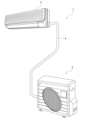
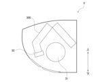
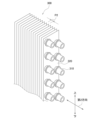
- FIG. 1 is an external view of an air conditioner according to an embodiment of the present disclosure. It is a schematic diagram of an outdoor unit. It is a schematic diagram of an indoor unit. It is a perspective view of a 1st heat exchanger. It is a sectional view of the first and second heat exchanger tubes. It is a sectional view of a first heat exchanger and a second heat exchanger.
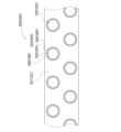
- FIG. 3 is a plan view of first and second fins. It is a perspective view of a 2nd heat exchanger. It is a sectional view of the 1st heat exchanger tube and the 2nd heat exchanger tube of a modification. It is a sectional view of the first fin of an embodiment. It is a sectional view of the second fin of an embodiment.
- an air conditioner 1 according to an embodiment of the present disclosure includes an outdoor unit 2, an indoor unit 3, and a connecting pipe 4.
- the outdoor unit 2 is installed outdoors.
- the indoor unit 3 is installed indoors.
- the indoor unit 3 here is attached to a wall or the like in the room.
- the connecting pipe 4 connects the outdoor unit 2 and the indoor unit 3.
- Such an air conditioner 1 can perform indoor cooling operation, heating operation, etc.
- the outdoor unit 2 includes a first heat exchanger 200, a first fan 21, a first drain pan 22, and the like.
- the first fan 21 sucks outdoor air into the outdoor unit 2 , supplies the outdoor air to the first heat exchanger 200 , and then discharges it outside the outdoor unit 2 .
- the first heat exchanger 200 exchanges heat between outdoor air and a refrigerant.
- the first heat exchanger 200 is a heat exchanger that functions as a refrigerant radiator during cooling operation, and functions as a refrigerant evaporator during heating operation.
- the first drain pan 22 receives water.
- the indoor unit 3 includes a second heat exchanger 300, a second fan 31, a second drain pan 32, and the like.
- the second fan 31 sucks indoor air into the indoor unit 3 , supplies the indoor air to the second heat exchanger 300 , and then discharges it to the outside of the indoor unit 3 .
- the second heat exchanger 300 performs heat exchange between the refrigerant and indoor air.
- the second heat exchanger 300 is a heat exchanger that functions as a refrigerant evaporator during cooling operation and as a refrigerant radiator during heating operation.
- the second drain pan 32 receives water.
- the first heat exchanger 200 includes a plurality of first heat exchanger tubes 210 and a plurality of first fins 220. ing.
- the first heat exchanger tube 210 and the first fin 220 are made of aluminum or an aluminum alloy.
- the first heat exchanger 200 of this embodiment is a cross-fin tube heat exchanger.
- the first heat exchanger tube 210 allows a refrigerant to flow inside.
- the first heat exchanger tube 210 has a cylindrical shape.
- the first heat exchanger tube 210 is a round tube.
- the first heat exchanger tube 210 is formed with a through hole through which a refrigerant to be heat exchanged with outdoor air in the first heat exchanger 200 passes.
- the through hole of the first heat exchanger tube 210 penetrates along the first direction.
- the first direction is the longitudinal direction.
- the first heat exchanger tube 210 includes a first base material 211 and a first sacrificial layer 212.
- the first sacrificial layer 212 is provided on the surface of the first heat exchanger tube 210.
- the first sacrificial layer 212 may be provided on the entire surface of the first heat exchanger tube 210, or may be provided on a part of the surface of the first heat exchanger tube 210, as shown in FIG. In other words, the first sacrificial layer 212 may be formed on the entire exposed outer surface, or may be formed on a portion of the exposed outer surface, as shown in FIG.
- the first sacrificial layer 212 is formed in a part of the first heat exchanger tube 210 in the thickness direction from the outer surface toward the inner surface through which the refrigerant flows, and is not formed over the entire thickness. In other words, in the first heat exchanger tube 210, the first sacrificial layer 212 is not formed on at least a portion of the inner surface through which the refrigerant flows. In this embodiment, the first sacrificial layer 212 is not formed on the entire inner surface of the first heat exchanger tube 210.
- the first sacrificial layer 212 has a lower potential than the first base material 211 of the first heat exchanger tube 210 and has a lower potential than the first fin 220.
- the potential difference between the potential of the first sacrificial layer 212 and the potential of the first base material 211 is, for example, 226 mV.
- the potential difference between the potential of the first sacrificial layer 212 and the potential of the first fin 220 is, for example, 180 mV.
- the first sacrificial layer 212 contains metal such as zinc (Zn) to lower the potential.
- the first sacrificial layer 212 of this embodiment is a zinc diffusion layer that is sprayed with zinc.
- the first sacrificial layer 212 on the outer surface side prevents corrosion of the first base material 211 on the inner surface side of the first heat exchanger tube 210 .
- the plurality of first heat exchanger tubes 210 are arranged in the vertical direction.
- the lowermost ends of the plurality of first heat exchanger tubes 210 are located above the water level of the first drain pan 22 (see FIG. 2).
- the lowest end of the plurality of first heat exchanger tubes 210 is located above the highest water level when the first drain pan 22 receives the maximum amount of water.
- the first fin 220 increases the heat transfer area between the first heat transfer tube 210 and the outdoor air, and promotes heat exchange between the refrigerant and the outdoor air.
- the first fins 220 are in contact with the first heat exchanger tubes 210.
- the first fins 220 have a lower potential than the first base material 211 of the first heat exchanger tube 210 and a nobler potential than the first sacrificial layer 212.
- the first base material 211, the first fin 220, and the first sacrificial layer 212 are arranged in descending order of potential.
- the potential difference between the potential of the first fin 220 and the potential of the first base material 211 is, for example, 46 mV.
- the first fin 220 of this embodiment contains zinc.
- the zinc content of the first fin 220 is preferably 0.5% by mass or more.
- the "zinc content” described in this specification is a value measured by, for example, emission spectrometry.
- the first fin 220 has a first main body portion 220a and a first surface layer 220b.
- the first surface layer 220b is provided on the surface of the first main body portion 220a.
- the first surface layer 220b is provided on both surfaces extending in the extending direction of the first main body portion 220a.
- the thickness W220b of the first surface layer 220b is smaller than the thickness W220a of the first main body portion 220a. Note that each thickness of the first fin 220 is the maximum value of the distance in the first direction from the outer surface toward the inside.
- the first surface layer 220b contains resin.
- the resin has electrical resistance.
- the electrical conductivity of the first surface layer 220b is lower than that of the first main body portion 220a.
- the first surface layer 220b is a layer formed by performing surface treatment on the surface of the first main body portion 220a.
- the first surface layer 220b imparts hydrophilicity, corrosion resistance, etc. to the first fin 220. Note that the first surface layer 220b may be one layer or may be multiple layers.
- the electrical resistance value of the first surface layer 220b is preferably 1 ⁇ 10 4 ⁇ or more and 1 ⁇ 10 10 ⁇ or less, and more preferably 1 ⁇ 10 5 ⁇ or more and 1 ⁇ 10 8 ⁇ or less.
- the plurality of first fins 220 are stacked in the first direction in which the first heat exchanger tube 210 extends (see FIG. 4).
- the plurality of first fins 220 extend in the vertical direction so as to intersect (orthogonally in FIG. 4) the first heat exchanger tubes 210.
- the plurality of first fins 220 are arranged in parallel and at equal intervals.
- the plurality of first fins 220 are arranged in the first direction at a predetermined fin pitch P1.
- the plurality of first fins 220 include a fin main body 221 and a first collar portion 222.
- the fin main body 221 is a flat member.
- the first collar portion 222 allows the first heat exchanger tube 210 to pass therethrough.
- the first collar portion 222 has a through hole through which the first heat exchanger tube 210 passes.
- the first collar portion 222 includes a first raised portion 223, a flat portion 224, a second raised portion 225, and a flange portion 226.
- the first raised portion 223, the flat portion 224, the second raised portion 225, and the flange portion 226 are made of one member.
- the first raised portion 223, the flat portion 224, the second raised portion 225, and the flange portion 226 are formed by nesting processing.
- the first raised portion 223 extends from the fin body 221 in the first direction.
- the first upright portion 223 is perpendicular to the fin body 221.
- the connecting portion between the first upright portion 223 and the fin main body 221 has a curved (R) shape.
- the flat portion 224 extends from the first upright portion 223 toward the first heat exchanger tube 210.
- the flat portion 224 is orthogonal to the first raised portion 223.
- the connecting portion between the flat portion 224 and the first raised portion 223 has a curved shape.
- the second raised portion 225 extends from the flat portion 224 along the first heat exchanger tube 210.
- the second upright portion 225 is in contact with the first heat exchanger tube 210 .
- the second raised portion 225 is perpendicular to the flat portion 224.
- the connecting portion between the second raised portion 225 and the flat portion 224 has a curved shape.
- the flange portion 226 extends outward from the second raised portion 225.
- the flange portion 226 is perpendicular to the second raised portion 225.
- the connecting portion between the flange portion 226 and the second raised portion 225 has a curved shape.
- the radius of curvature of this connecting portion is 0.2 mm or more.
- One flat portion 224 is in contact with a flange portion 226 of another adjacent first fin 220.
- Flat portion 224 and flange portion 226 extend in the same direction.
- the second heat exchanger 300 includes a plurality of second heat exchanger tubes 310 and a plurality of second fins 320.
- the second heat exchanger tube 310 and the second fin 320 are made of aluminum or an aluminum alloy.
- the second heat exchanger 300 of this embodiment is a cross-fin tube heat exchanger.
- the second heat exchanger tube 310 allows a refrigerant to flow inside.
- the second heat exchanger tube 310 has a cylindrical shape.
- the second heat exchanger tube 310 is a round tube.
- the second heat exchanger tube 310 is formed with a through hole through which the refrigerant to be heat exchanged with indoor air in the second heat exchanger 300 passes.
- the through hole of the second heat exchanger tube 310 penetrates along the second direction.
- the second direction is the longitudinal direction.
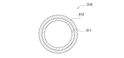
- the second heat exchanger tube 310 includes a second base material 311 and a second sacrificial layer 312.
- the second sacrificial layer 312 is provided on the surface of the second heat exchanger tube 310.
- the second sacrificial layer 312 may be provided on the entire surface of the second heat exchanger tube 310, or may be provided on a part of the surface of the second heat exchanger tube 310, as shown in FIG. In other words, the second sacrificial layer 312 may be formed on the entire exposed outer surface, or may be formed on a portion of the exposed outer surface, as shown in FIG.
- the second sacrificial layer 312 is formed in a part of the second heat exchanger tube 310 in the thickness direction from the outer surface to the inner surface through which the refrigerant flows, and is not formed over the entire thickness. In other words, in the second heat exchanger tube 310, the second sacrificial layer 312 is not formed on at least a portion of the inner surface through which the refrigerant flows. In this embodiment, the second sacrificial layer 312 is not formed on the entire inner surface of the second heat exchanger tube 310.
- the second sacrificial layer 312 has a lower potential than the second base material 311 of the second heat exchanger tube 310 and has a lower potential than the second fin 320.
- the second sacrificial layer 312 contains metal such as zinc to lower the potential.
- the second sacrificial layer 312 of this embodiment is a zinc diffusion layer on which zinc is sprayed.
- the second sacrificial layer 312 on the outer surface side prevents corrosion of the second base material 311 on the inner surface side of the second heat exchanger tube 310 .
- the plurality of second heat exchanger tubes 310 are arranged in the vertical direction.
- the lowermost ends of the plurality of second heat exchanger tubes 310 are located above the water level of the second drain pan 32 (see FIG. 3).
- the lowest end of the plurality of second heat exchanger tubes 310 is located above the highest water level when the second drain pan 32 receives the maximum amount of water.
- the second fin 320 increases the heat transfer area between the second heat transfer tube 310 and the indoor air, and promotes heat exchange between the refrigerant and the indoor air.
- the second fins 320 are in contact with the second heat exchanger tubes 310.
- the second fins 320 have a lower potential than the second base material 311 of the second heat exchanger tube 310 and a nobler potential than the second sacrificial layer 312.
- the second base material 311, the second fin 320, and the second sacrificial layer 312 are arranged in descending order of potential.
- the second fin 320 of this embodiment contains zinc.
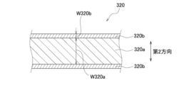
- the second fin 320 has a second main body portion 320a and a second surface layer 320b.
- the second surface layer 320b is provided on the surface of the second main body portion 320a.
- the second surface layer 320b is provided on both surfaces extending in the extending direction of the second main body portion 320a.
- the thickness W320b of the second surface layer 320b is smaller than the thickness W320a of the second main body portion 320a. Note that each thickness of the second fin 320 is the maximum value of the distance in the second direction from the outer surface toward the inside.
- the second surface layer 320b contains resin.
- the resin has electrical resistance.
- the electrical conductivity of the second surface layer 320b is lower than that of the second main body portion 320a.
- the second surface layer 320b is a layer formed by performing surface treatment on the surface of the second main body portion 320a.
- the second surface layer 320b imparts hydrophilicity, corrosion resistance, etc. to the second fin 320. Note that the second surface layer 320b may be one layer or may be multiple layers.
- the plurality of second fins 320 are stacked in the second direction in which the second heat exchanger tube 310 extends (see FIG. 8).
- the plurality of second fins 320 extend in the vertical direction so as to intersect (orthogonally in FIG. 8) the second heat exchanger tube 310.
- the plurality of second fins 320 are arranged in parallel and at equal intervals.
- the plurality of second fins 320 are arranged in the second direction at a predetermined fin pitch P2.
- the second direction and the first direction are shown as the same direction for convenience, but the second direction may be different from the first direction.
- the plurality of second fins 320 include a fin main body 321 and a second collar portion 322.
- the fin main body 321 is a flat member.
- the second collar portion 322 allows the second heat exchanger tube 310 to pass therethrough.
- the second collar portion 322 has a through hole through which the second heat exchanger tube 310 passes.
- the second collar portion 322 includes a first raised portion 323, a flat portion 324, a second raised portion 325, and a flange portion 326.
- the first raised portion 323, the flat portion 324, the second raised portion 325, and the flange portion 326 are composed of one member.
- the first raised portion 323, the flat portion 324, the second raised portion 325, and the flange portion 326 are formed by nesting processing.
- the first raised portion 323 extends from the fin body 321 in the second direction.
- the first upright portion 323 is orthogonal to the fin body 321.
- the connecting portion between the first upright portion 323 and the fin main body 321 has a curved (R) shape.
- the flat portion 324 extends from the first raised portion 323 toward the second heat exchanger tube 310.
- the flat portion 324 is perpendicular to the first raised portion 323.
- the connecting portion between the flat portion 324 and the first raised portion 323 has a curved shape.
- the second raised portion 325 extends from the flat portion 324 along the second heat exchanger tube 310.
- the second upright portion 325 is in contact with the second heat exchanger tube 310 .
- the second raised portion 325 is orthogonal to the flat portion 324.
- the connecting portion between the second raised portion 325 and the flat portion 324 has a curved shape.
- the flange portion 326 extends outward from the second raised portion 325.
- the flange portion 326 is orthogonal to the second raised portion 325.
- the connecting portion between the flange portion 326 and the second upright portion 325 has a curved shape.
- the radius of curvature of this connecting portion is 0.2 mm or more.
- One flat portion 324 is in contact with a flange portion 326 of another adjacent second fin 320.
- Flat portion 324 and flange portion 326 extend in the same direction.
- the fin pitch P1 of the first fin 220 shown in FIG. 4 is the same as that of the second fin 320 shown in FIG. is larger than the fin pitch P2.
- the fin pitch P1 is the distance between adjacent first fins 220.
- the fin pitch P1 is the distance between opposing surfaces of adjacent first fins 220.
- the fin pitch P2 is the distance between adjacent second fins 320.
- the fin pitch P2 is the distance between opposing surfaces of adjacent second fins 320.
- the difference between the fin pitch P1 of the first fin 220 and the fin pitch P2 of the second fin 320 is 0.1 mm or more and 0.3 mm or less.
- the pitch difference (fin pitch P1 - fin pitch P2) is 0.1 mm or more and 0.3 mm or less.
- the fin pitch P1 of the first fins 220 is more than 1.0 times and less than 1.3 times the fin pitch P2 of the second fins 320.
- the fin pitch ratio is greater than 1.0 and less than 1.3.
- the fin pitch P1 of the first fins 220 is 1.4 mm or more and 1.5 mm or less.
- the fin pitch P2 of the second fins 320 is 1.2 mm or more and 1.4 mm or less.
- the outer diameter of the first heat transfer tube 210 and the outer diameter of the second heat transfer tube 310 are the same.
- the inner diameter of the first heat exchanger tube 210 and the inner diameter of the second heat exchanger tube 310 are the same.
- the material of the first heat exchanger tube 210 and the material of the second heat exchanger tube 310 are the same. Specifically, the material of the first base material 211 and the material of the second base material 311 are the same. The material of the first sacrificial layer 212 and the material of the second sacrificial layer 312 are the same.
- the thickness of the first sacrificial layer 212 and the thickness of the second sacrificial layer 312 are the same.
- the thickness of the first and second sacrificial layers 212, 312 is the maximum thickness.
- the thickness of the first base material 211 and the thickness of the second base material 311 are the same.
- the thickness of the first and second base materials 211 and 311 is the maximum thickness.
- the first heat exchanger tube 210 and the second heat exchanger tube are the same. Therefore, when manufacturing the air conditioner 1, after manufacturing cylindrical heat exchanger tubes made of the same material and the same size as the first heat exchanger tube 210 and the second heat exchanger tube 310, the first heat exchanger 200 and the second heat exchanger tube 310 are manufactured.
- the heat exchanger tube is processed to match the shape of the second heat exchanger 300. Thereby, the cost of the first heat exchanger tube 210 and the second heat exchanger tube 310 can be reduced.
- the material of the first fin 220 and the material of the second fin 320 may be the same, but preferably the zinc content of the first fin 220 is the same as that of the second fin 320.
- the zinc content of the first fins 220 is greater than the zinc content of the second fins 320 by 0.2% by mass or more.
- the insulation performance of the first surface layer 220b of the first fin 220 and the insulation performance of the second surface layer 320b of the second fin 320 are the same.
- the electrical conductivity of the first surface layer 220b of the first fin 220 and the electrical conductivity of the second surface layer 320b of the second fin 320 are the same.
- "The same” includes a ratio of electrical conductivity of each other within 10%.
- the electrical conductivity of the first surface layer 220b and the electrical conductivity of the second surface layer 320b may be completely the same; This includes a case where the ratio of the electrical conductivity of the layer 220b (electrical conductivity of the first surface layer 220b/electrical conductivity of the second surface layer 320b) is 1.1 times or less.
- the thickness of the first fin 220 and the thickness of the second fin 320 may be the same, but are different in this embodiment.
- the thickness of the first fin 220 is smaller than the thickness of the second fin.
- the thickness W220a of the first body portion 220a of the first fin 220 shown in FIG. 10 is smaller than the thickness W320a of the second body portion 320a of the second fin 320 shown in FIG.
- the thickness W220b of the first surface layer 220b of the first fin 220 shown in FIG. 10 is larger than the thickness W320b of the second surface layer 320b of the second fin 320 shown in FIG.
- the thickness W220b of the first surface layer 220b is preferably 1.1 times or more, more preferably 1.2 times or more, and 1.5 times or more the thickness W320b of the second surface layer 320b. is even more preferable.
- the electrical resistance value of the first surface layer 220b is preferably 1.2 times or more the electrical resistance value of the second surface layer 320b.
- the air conditioner 1 includes an outdoor unit 2 and an indoor unit 3.
- Outdoor unit 2 includes a first heat exchanger 200.
- the first heat exchanger 200 includes a first heat exchanger tube 210 and a plurality of first fins 220.
- the first heat exchanger tube 210 is made of aluminum or aluminum alloy.
- the plurality of first fins 220 are made of aluminum or aluminum alloy.
- Indoor unit 3 includes a second heat exchanger 300.
- the second heat exchanger 300 includes a second heat exchanger tube 310 and a plurality of second fins 320.
- the second heat exchanger tube 310 is made of aluminum or aluminum alloy.
- the plurality of second fins 320 are made of aluminum or aluminum alloy.
- a first sacrificial layer 212 is provided on the surface of the first heat exchanger tube 210.
- the first sacrificial layer 212 has a lower potential than the first base material 211 of the first heat exchanger tube 210 and has a lower potential than the first fin 220 .
- the fin pitch P1 of the first fins 220 is larger than the fin pitch P2 of the second fins 320.
- the first heat exchanger tube 210 made of aluminum or aluminum alloy is provided with the first sacrificial layer 212 which is more base in potential than the first base material 211. Corrosion of the first base material 211 can be suppressed.
- the first sacrificial layer 212 is more base in potential than the first fin 220 made of aluminum or aluminum alloy. Therefore, when water droplets are attached across the first fins 220 and the first sacrificial layer 212, a potential difference is generated, and the first sacrificial layer 212 is consumed by the first fins 220. If the first sacrificial layer 212 is rapidly consumed, the first base material 211 cannot be protected.
- the first heat exchanger 200 of the outdoor unit 2 installed outdoors is more susceptible to salt damage than the second heat exchanger 300 of the indoor unit 3 installed indoors. Since it is easy to receive heat, the fin pitch P1 of the first fins 220 of the first heat exchanger 200 is made larger than the fin pitch P2 of the second fins 320 of the second heat exchanger 300. Therefore, by reducing the number of first fins 220, the surface area of the first fins 220 in contact with the first sacrificial layer 212 of the first heat exchanger tube 210 can be reduced.
- the first heat exchanger tube 210 and the second heat exchanger tube 310 have a cylindrical shape.
- the first fins 220 attached to the first heat exchanger tube 210 having a cylindrical shape and the second fins 320 attached to the second heat exchanger tube 310 are required to have workability.
- the first fin 220 has a nobler potential than the first sacrificial layer 212, deterioration in workability of the first fin 220 can be suppressed. Therefore, it can be suitably used in an air conditioner 1 that includes a first heat exchanger 200 having a cylindrical first heat exchanger tube 210 and a second heat exchanger 300 having a cylindrical second heat exchanger tube 310. I can do it.
- a first surface layer 220b containing resin is provided on the surface of the first fin 220.
- the corrosion rate of the first sacrificial layer 212 can be slowed down by the electrical resistance between the first surface layer 220b containing resin and the first heat exchanger tube 210.
- a second surface layer 320b containing resin is provided on the surface of the second fin 320.
- the thickness W220b of the first surface layer 220b is greater than the thickness W320b of the second surface layer 320b.
- the electric resistance between the first surface layer 220b of the outdoor unit 2 and the first heat exchanger tube 210 which is susceptible to salt damage, is calculated from the electric resistance between the second surface layer 320b of the indoor unit 3 and the second heat exchanger tube 310. can also be made larger. Therefore, the corrosion rate of the first sacrificial layer 212 can be further reduced.
- a second sacrificial layer 312 is provided on the surface of the second heat exchanger tube 310.
- the second sacrificial layer 312 has a lower potential than the second base material 311 of the second heat exchanger tube 310 and has a lower potential than the second fin 320 .
- the second heat exchanger tube 310 made of aluminum or aluminum alloy is provided with the second sacrificial layer 312 which is more base in potential than the second base material 311, corrosion of the second base material 311 is suppressed. can. Furthermore, since the second sacrificial layer 312 has a lower potential than the second fin 320, deterioration in the workability of the second fin 320 can be suppressed.
- the difference (P1-P2) between the fin pitch P1 of the first fin 220 and the fin pitch P2 of the second fin 320 is 0.1 mm or more and 0.3 mm or less. Thereby, corrosion of the first sacrificial layer 212 can be further suppressed.
- the fin pitch P1 of the first fins 220 is more than 1.0 times and less than 1.3 times the fin pitch P2 of the second fins 320. Thereby, corrosion of the first sacrificial layer 212 can be further suppressed.
- the thickness of the first sacrificial layer 212 and the thickness of the second sacrificial layer 312 are the same. In this way, since the first sacrificial layer 212 of the first heat exchanger tube 210 and the second sacrificial layer 312 of the second heat exchanger tube 310 can be shared, the production efficiency of the first heat exchanger 200 and the second heat exchanger 300 is improved. can be improved.
- the outer diameter of the first heat exchanger tube 210 and the outer diameter of the second heat exchanger tube 310 are the same. In this way, since the outer diameter of the first heat exchanger tube 210 and the outer diameter of the second heat exchanger tube 310 can be made common, the production efficiency of the first heat exchanger 200 and the second heat exchanger 300 can be improved. .
- the material of the first heat exchanger tube 210 and the material of the second heat exchanger tube 310 are the same. In this way, since the material of the first heat exchanger tube 210 and the material of the second heat exchanger tube 310 can be made common, the production efficiency of the first heat exchanger 200 and the second heat exchanger 300 can be improved.
- the outdoor unit 2 further includes a first drain pan 22 that receives water.
- the indoor unit 3 further includes a second drain pan 32 that receives water.
- the lowermost ends of the plurality of first heat exchanger tubes 210 are located above the water level of the first drain pan 22.
- the lowermost ends of the plurality of second heat exchanger tubes 310 are located above the water level of the second drain pan 32.
- the plurality of first fins 220 are stacked in the first direction in which the first heat exchanger tubes 210 extend, and have a first collar portion 222 through which the first heat exchanger tubes 210 are passed.
- the first collar portion 222 includes a first raised portion 223 , a flat portion 224 , a second raised portion 225 , and a flange portion 226 .
- the first raised portion 223 extends from the fin body 221 in the first direction.
- the flat portion 224 extends from the first upright portion 223 toward the first heat exchanger tube 210 .
- the second raised portion 225 extends from the flat portion 224 along the first heat exchanger tube 210 .
- the flange portion 226 extends outward from the second raised portion 225 .
- One flat portion 224 contacts a flange portion 226 of another adjacent first fin 220 .
- the plurality of second fins 320 are stacked in the second direction in which the second heat exchanger tube 310 extends, and have a second collar portion 322 through which the second heat exchanger tube passes.
- the second collar portion 322 includes a first raised portion 323 , a flat portion 324 , a second raised portion 325 , and a flange portion 326 .
- the first upright portion 323 extends from the fin body 321 in the second direction.
- the flat portion 324 extends from the first upright portion 323 toward the second heat exchanger tube 310.
- the second raised portion 325 extends from the flat portion 324 along the second heat exchanger tube 310 .
- the flange portion 326 extends outward from the second raised portion 325 .
- One flat portion 324 contacts a flange portion 326 of another adjacent second fin 320 .
- a gap is created between the first collar portion 222 of the first fin 220 and the second collar portion 322 of the second fin 320 that are stacked. Specifically, for example, a gap is created between the connecting portion between the first upright portion 223 and the flat portion 224 of one first fin 220 and the flange portion 226 of another first fin 220 .
- the problem of corrosion increases due to water droplets adhering to this gap.
- the air conditioner 1 of this embodiment corrosion of the first sacrificial layer 212 by the first fins 220 can be suppressed, so even if the first fins 220 and the second fins 320 have the above structure, corrosion will not occur. Can solve problems. Therefore, it can be suitably used in the air conditioner 1 including the first heat exchanger 200 having the first fins 220 having the above structure and the second heat exchanger 300 having the second fins 320 having the above structure. .
- the portion has a curved shape with a radius of curvature of 0.2 mm or more.
- the air conditioner 1 of the present embodiment can suppress the corrosion of the first sacrificial layer 212 caused by the first fins 220, the first heat exchanger 200 having the first fins 220 having the above structure, It can be suitably used in an air conditioner 1 including a second heat exchanger 300 having two fins 320.
- the zinc content of the first fins 220 is preferably higher than the zinc content of the second fins 320.
- the zinc content of the first fin 220 of the outdoor unit 2, which is susceptible to salt damage is higher than the zinc content of the second fin 320 of the indoor unit 3, it is possible to lower the potential of the first fin 220. can. Therefore, the potential difference between the first fin 220 and the first sacrificial layer 212 can be reduced. Therefore, corrosion of the first sacrificial layer 212 can be further suppressed.
- the second sacrificial layer 312 has a lower potential than the second base material 311 of the second heat exchanger tube 310 and has a lower potential than the second fin 320. It is noble.
- the second heat exchanger tube 310 made of aluminum or aluminum alloy is provided with the second sacrificial layer 312 which is more base in potential than the second base material 311, corrosion of the second base material 311 is suppressed. can.
- the second sacrificial layer 312 has a nobler potential than the second fin 320, corrosion of the second sacrificial layer 312 by the second fin 320 can be suppressed even if the fin pitch P2 of the second fin 320 is small. be able to.
- the first sacrificial layer 212 of the first heat exchanger tube 210 and the second sacrificial layer 312 of the second heat exchanger tube 310 are, for example, a diffusion layer sprayed with zinc, as shown in FIG.
- the invention is not limited thereto.
- cladding materials are used as the base material and the sacrificial layer.
- the first heat exchanger tube 210 is formed using a clad material in which a metal serving as the first base material 211 and a metal serving as the first sacrificial layer 212 are bonded together.
- the second heat exchanger tube 310 is formed using a clad material in which a metal serving as the second base material 311 and a metal serving as the second sacrificial layer 312 are bonded together.
- both the first fin 220 and the second fin 320 are provided with a surface layer, but the present invention is not limited thereto.
- the first fin 220 is provided with the first surface layer 220b, but the second fin 320 is not provided with the second surface layer 320b.
- both the first fin 220 and the second fin 320 do not need to be provided with a surface layer.
- Air conditioner 2 Outdoor unit 3: Indoor unit 22: First drain pan 32: Second drain pan 200: First heat exchanger 210: First heat transfer tube 211: First base material (base material) 212: First sacrificial layer 220: First fin 220b: First surface layer 221, 321: Fin body 222: First collar portion 223, 323: First raised portion 224, 324: Flat portion 225, 325: Second raised portion Upper part 226, 326: Flange part 300: Second heat exchanger 310: Second heat exchanger tube 311: Second base material (base material) 312: Second sacrificial layer 320: Second fin 320b: Second surface layer 322: Second collar portion P1, P2: Fin pitch W220b, W320b: Thickness
Landscapes
- Engineering & Computer Science (AREA)
- Mechanical Engineering (AREA)
- General Engineering & Computer Science (AREA)
- Physics & Mathematics (AREA)
- Thermal Sciences (AREA)
- Chemical & Material Sciences (AREA)
- Combustion & Propulsion (AREA)
- Geometry (AREA)
- Heat-Exchange Devices With Radiators And Conduit Assemblies (AREA)
Abstract
Priority Applications (3)
| Application Number | Priority Date | Filing Date | Title |
|---|---|---|---|
| EP23780897.7A EP4502505A4 (fr) | 2022-03-31 | 2023-03-30 | Climatiseur |
| CN202380030380.0A CN118974506A (zh) | 2022-03-31 | 2023-03-30 | 空调机 |
| US18/900,065 US20250020416A1 (en) | 2022-03-31 | 2024-09-27 | Air conditioner |
Applications Claiming Priority (4)
| Application Number | Priority Date | Filing Date | Title |
|---|---|---|---|
| JP2022060705 | 2022-03-31 | ||
| JP2022-060705 | 2022-03-31 | ||
| JP2022-153804 | 2022-09-27 | ||
| JP2022153804A JP7401812B2 (ja) | 2022-03-31 | 2022-09-27 | 空気調和機 |
Related Child Applications (1)
| Application Number | Title | Priority Date | Filing Date |
|---|---|---|---|
| US18/900,065 Continuation US20250020416A1 (en) | 2022-03-31 | 2024-09-27 | Air conditioner |
Publications (1)
| Publication Number | Publication Date |
|---|---|
| WO2023190889A1 true WO2023190889A1 (fr) | 2023-10-05 |
Family
ID=88202797
Family Applications (1)
| Application Number | Title | Priority Date | Filing Date |
|---|---|---|---|
| PCT/JP2023/013216 Ceased WO2023190889A1 (fr) | 2022-03-31 | 2023-03-30 | Climatiseur |
Country Status (3)
| Country | Link |
|---|---|
| US (1) | US20250020416A1 (fr) |
| EP (1) | EP4502505A4 (fr) |
| WO (1) | WO2023190889A1 (fr) |
Citations (6)
| Publication number | Priority date | Publication date | Assignee | Title |
|---|---|---|---|---|
| JPH11211377A (ja) * | 1998-01-26 | 1999-08-06 | Kobe Steel Ltd | 熱交換器用アルミニウム又はアルミニウム合金フィン材及びその製造方法 |
| JP2001304783A (ja) | 2000-04-14 | 2001-10-31 | Daikin Ind Ltd | 室外熱交換器、室内熱交換器、及び空気調和装置 |
| WO2015097821A1 (fr) * | 2013-12-26 | 2015-07-02 | 東芝キヤリア株式会社 | Climatiseur et échangeur thermique |
| JP2018197634A (ja) * | 2017-05-24 | 2018-12-13 | 株式会社デンソーエアクール | 熱交換器 |
| WO2019239990A1 (fr) * | 2018-06-12 | 2019-12-19 | ダイキン工業株式会社 | Échangeur de chaleur intérieur et dispositif de climatisation |
| JP2020051731A (ja) * | 2018-09-28 | 2020-04-02 | 三菱アルミニウム株式会社 | 親水性フィンおよび熱交換器 |
Family Cites Families (7)
| Publication number | Priority date | Publication date | Assignee | Title |
|---|---|---|---|---|
| JP5610714B2 (ja) * | 2009-06-24 | 2014-10-22 | 株式会社Uacj | アルミニウム合金製熱交換器 |
| WO2013069299A1 (fr) | 2011-11-10 | 2013-05-16 | パナソニック株式会社 | Ailette de transfert de chaleur, échangeur de chaleur à tube à ailettes et dispositif de pompe à chaleur |
| JP2014095524A (ja) * | 2012-11-12 | 2014-05-22 | Hitachi Appliances Inc | 空気調和機 |
| US10175009B2 (en) * | 2015-01-07 | 2019-01-08 | Mitsubishi Electric Corporation | Method for manufacturing refrigerant distributor, refrigerant distributor manufacturing apparatus, refrigerant distributor, heat exchanger, and air-conditioning device |
| JP6611528B2 (ja) | 2015-09-09 | 2019-11-27 | 日立ジョンソンコントロールズ空調株式会社 | 空気調和機およびその製造方法 |
| JP2017180991A (ja) * | 2016-03-31 | 2017-10-05 | 株式会社Uacj | 熱交換器用フィン材及び熱交換器 |
| JP2019215118A (ja) | 2018-06-12 | 2019-12-19 | ダイキン工業株式会社 | 熱交換器及び空気調和装置 |
-
2023
- 2023-03-30 WO PCT/JP2023/013216 patent/WO2023190889A1/fr not_active Ceased
- 2023-03-30 EP EP23780897.7A patent/EP4502505A4/fr active Pending
-
2024
- 2024-09-27 US US18/900,065 patent/US20250020416A1/en active Pending
Patent Citations (6)
| Publication number | Priority date | Publication date | Assignee | Title |
|---|---|---|---|---|
| JPH11211377A (ja) * | 1998-01-26 | 1999-08-06 | Kobe Steel Ltd | 熱交換器用アルミニウム又はアルミニウム合金フィン材及びその製造方法 |
| JP2001304783A (ja) | 2000-04-14 | 2001-10-31 | Daikin Ind Ltd | 室外熱交換器、室内熱交換器、及び空気調和装置 |
| WO2015097821A1 (fr) * | 2013-12-26 | 2015-07-02 | 東芝キヤリア株式会社 | Climatiseur et échangeur thermique |
| JP2018197634A (ja) * | 2017-05-24 | 2018-12-13 | 株式会社デンソーエアクール | 熱交換器 |
| WO2019239990A1 (fr) * | 2018-06-12 | 2019-12-19 | ダイキン工業株式会社 | Échangeur de chaleur intérieur et dispositif de climatisation |
| JP2020051731A (ja) * | 2018-09-28 | 2020-04-02 | 三菱アルミニウム株式会社 | 親水性フィンおよび熱交換器 |
Non-Patent Citations (1)
| Title |
|---|
| See also references of EP4502505A4 |
Also Published As
| Publication number | Publication date |
|---|---|
| US20250020416A1 (en) | 2025-01-16 |
| EP4502505A4 (fr) | 2025-07-09 |
| EP4502505A1 (fr) | 2025-02-05 |
Similar Documents
| Publication | Publication Date | Title |
|---|---|---|
| CN103026165B (zh) | 空气调节器用螺旋热交换器 | |
| CN103946662B (zh) | 空调用蛇管式换热器 | |
| CN105651081B (zh) | 双排折弯式换热器及其制造方法 | |
| CA2753385C (fr) | Echangeur thermique | |
| JP7401812B2 (ja) | 空気調和機 | |
| JP6074648B2 (ja) | 管部材の接合体、及び冷凍サイクル装置の熱交換器 | |
| US20250020415A1 (en) | Air conditioner | |
| JP2018021756A (ja) | フィン・アンド・チューブ型熱交換器用伝熱管及びそれを用いたフィン・アンド・チューブ型熱交換器 | |
| WO2023190889A1 (fr) | Climatiseur | |
| CN110785622A (zh) | 热交换器用管 | |
| US12510300B2 (en) | Heat exchanger and air conditioning system | |
| JP2012184920A (ja) | 空気調和機 | |
| CN118974506A (zh) | 空调机 | |
| CN207163023U (zh) | 换热器及家用电器 | |
| CN107270589B (zh) | 换热器及家用电器 | |
| CN209672487U (zh) | 管翅式换热器、空调室外机及空调器 | |
| JP2011185589A (ja) | 空気調和機用サーペンタイン熱交換器 | |
| JP2012032121A (ja) | 熱交換器、この熱交換器を備えた空気調和機、及びこの熱交換器の製造方法 | |
| CN223122023U (zh) | 一种换热器和空调器 | |
| JP2006234355A (ja) | 熱交換器 | |
| JP5835907B2 (ja) | 熱交換器 | |
| JP2005140451A (ja) | フィン部材を外装した伝熱管 | |
| JP2021105477A (ja) | 熱交換器 | |
| CN103438619A (zh) | 复合式翅片蒸发器 |
Legal Events
| Date | Code | Title | Description |
|---|---|---|---|
| 121 | Ep: the epo has been informed by wipo that ep was designated in this application |
Ref document number: 23780897 Country of ref document: EP Kind code of ref document: A1 |
|
| WWE | Wipo information: entry into national phase |
Ref document number: 202380030380.0 Country of ref document: CN |
|
| WWE | Wipo information: entry into national phase |
Ref document number: 202417079873 Country of ref document: IN |
|
| WWE | Wipo information: entry into national phase |
Ref document number: 2023780897 Country of ref document: EP |
|
| ENP | Entry into the national phase |
Ref document number: 2023780897 Country of ref document: EP Effective date: 20241031 |
|
| NENP | Non-entry into the national phase |
Ref country code: DE |