WO2024085076A1 - プレスブレーキ及びプレスブレーキ制御方法 - Google Patents
プレスブレーキ及びプレスブレーキ制御方法 Download PDFInfo
- Publication number
- WO2024085076A1 WO2024085076A1 PCT/JP2023/037146 JP2023037146W WO2024085076A1 WO 2024085076 A1 WO2024085076 A1 WO 2024085076A1 JP 2023037146 W JP2023037146 W JP 2023037146W WO 2024085076 A1 WO2024085076 A1 WO 2024085076A1
- Authority
- WO
- WIPO (PCT)
- Prior art keywords
- angle
- metal
- amount
- sheet
- upper table
- Prior art date
- Legal status (The legal status is an assumption and is not a legal conclusion. Google has not performed a legal analysis and makes no representation as to the accuracy of the status listed.)
- Ceased
Links
Images


Classifications
-
- B—PERFORMING OPERATIONS; TRANSPORTING
- B21—MECHANICAL METAL-WORKING WITHOUT ESSENTIALLY REMOVING MATERIAL; PUNCHING METAL
- B21D—WORKING OR PROCESSING OF SHEET METAL OR METAL TUBES, RODS OR PROFILES WITHOUT ESSENTIALLY REMOVING MATERIAL; PUNCHING METAL
- B21D5/00—Bending sheet metal along straight lines, e.g. to form simple curves
- B21D5/004—Bending sheet metal along straight lines, e.g. to form simple curves with program control
-
- B—PERFORMING OPERATIONS; TRANSPORTING
- B21—MECHANICAL METAL-WORKING WITHOUT ESSENTIALLY REMOVING MATERIAL; PUNCHING METAL
- B21D—WORKING OR PROCESSING OF SHEET METAL OR METAL TUBES, RODS OR PROFILES WITHOUT ESSENTIALLY REMOVING MATERIAL; PUNCHING METAL
- B21D5/00—Bending sheet metal along straight lines, e.g. to form simple curves
- B21D5/006—Bending sheet metal along straight lines, e.g. to form simple curves combined with measuring of bends
-
- B—PERFORMING OPERATIONS; TRANSPORTING
- B21—MECHANICAL METAL-WORKING WITHOUT ESSENTIALLY REMOVING MATERIAL; PUNCHING METAL
- B21D—WORKING OR PROCESSING OF SHEET METAL OR METAL TUBES, RODS OR PROFILES WITHOUT ESSENTIALLY REMOVING MATERIAL; PUNCHING METAL
- B21D5/00—Bending sheet metal along straight lines, e.g. to form simple curves
- B21D5/02—Bending sheet metal along straight lines, e.g. to form simple curves on press brakes without making use of clamping means
-
- G—PHYSICS
- G01—MEASURING; TESTING
- G01B—MEASURING LENGTH, THICKNESS OR SIMILAR LINEAR DIMENSIONS; MEASURING ANGLES; MEASURING AREAS; MEASURING IRREGULARITIES OF SURFACES OR CONTOURS
- G01B11/00—Measuring arrangements characterised by the use of optical techniques
- G01B11/26—Measuring arrangements characterised by the use of optical techniques for measuring angles or tapers; for testing the alignment of axes
Definitions
- This disclosure relates to a press brake and a press brake control method.
- the press brake has an upper table on which the punch is attached and a lower table on which the die is attached.
- the upper table is lowered onto the lower table, and the metal sheet placed on the die is sandwiched between the punch and the die and bent (see Patent Document 1).
- the operator uses a digital bending angle meter called a digital protractor to measure whether the sheet metal bent in this way has actually been bent to the target bending angle. This is because the amount of springback varies depending on the thickness or hardness of the sheet metal, so it is necessary to confirm whether the sheet metal has actually been bent to the target bending angle. It takes a certain amount of time to measure the bending angle of the bent sheet metal with a digital bending angle meter, which lengthens the processing time from the start of bending the sheet metal to checking the bending angle after bending is completed. It is desirable to shorten the processing time as much as possible.
- a first aspect of one or more embodiments includes an upper table on which a punch is attached, a lower table on which a die is attached, a table lifting mechanism for raising and lowering the upper table or the lower table, an angle sensor for measuring the angle of the metal sheet when the metal sheet is sandwiched between the punch and the die and the upper table or the lower table is raised and lowered by the table lifting mechanism to bend the metal sheet, and a bending angle of the metal sheet calculated based on the angle of the metal sheet measured by the angle sensor, and a bending angle of the metal sheet calculated based on the angle of the metal sheet measured by the table lifting mechanism.
- control device for controlling lifting and lowering of the upper table or the lower table
- the control device when controlling the lifting and lowering of the upper table or the lower table to bend the metal sheet to a target bend angle, controls the table lifting mechanism to lower the upper table by a first depth value or raise the lower table by the first depth value during a pre-bending period so as to bend the metal sheet to a predetermined pre-bend angle which is wider than the target bend angle, calculates a first bend angle of the metal sheet bent to the pre-bend angle based on an angle of the metal sheet measured by the angle sensor, and ....
- the table lifting mechanism is controlled to raise the upper table or lower the lower table so as to unload the metal sheet while maintaining a state in which the punch is in contact with the metal sheet, a second bending angle of the metal sheet is calculated based on the angle of the metal sheet measured by the angle sensor while the metal sheet is unloaded during the unloading period, and a springback amount based on a difference between the second bending angle and the first bending angle is calculated.
- a second bending angle of the metal sheet is calculated taking into account the springback amount for bending the metal sheet to the target bending angle.
- a press brake is provided that calculates a depth value, controls the table lifting mechanism to lower the upper table by the second depth value or raise the lower table by the second depth value, and controls the table lifting mechanism to raise the upper table or lower the lower table so as to unload the sheet metal while maintaining the punch in contact with the sheet metal during the final angle measurement period after the sheet metal is bent to the target bend angle, and calculates the final bend angle of the sheet metal based on the angle of the sheet metal measured by the angle sensor.
- the sheet metal is unloaded while the punch remains in contact with the sheet metal, and the final bend angle of the sheet metal is calculated based on the angle of the sheet metal measured by the angle sensor. Therefore, the operator does not need to use a digital bending angle meter to measure whether the sheet metal has actually been bent to the target bend angle. This can shorten the processing time from the start of bending the sheet metal to checking the bend angle after bending is completed.
- a second aspect of one or more embodiments is a press brake control device that includes an upper table on which a punch is attached, a lower table on which a die is attached, a table lifting mechanism that raises and lowers the upper table or the lower table, and an angle sensor that measures the angle of the metal sheet being bent by being sandwiched between the punch and the die, the press brake control device controls the table lifting mechanism to lower the upper table by a first depth value or raise the lower table by the first depth value during a pre-bending period so as to bend the metal sheet to a predetermined pre-bending angle that is wider than a target bending angle, calculates a first bending angle of the metal sheet bent to the pre-bending angle based on the angle of the metal sheet measured by the angle sensor, and controls the table lifting mechanism to raise the upper table or lower the lower table so as to unload the metal sheet while maintaining the punch in contact with the metal sheet during an unloading period after the metal sheet has been bent to the pre-bending angle.
- the press brake control method includes: controlling a table lifting mechanism to lift the upper table by the second depth value or the lower table by the second depth value; controlling the table lifting mechanism to lift the upper table by the second depth value or the lower table by the second depth value; and controlling the table lifting mechanism to lift the upper table by the second depth value or the lower table by the second depth value during a final angle measurement period after the sheet metal is bent to the target bend angle, while maintaining the punch in contact with the sheet metal, to unload the sheet metal.
- the press brake control method includes controlling a table lifting mechanism to lift the upper table by the second depth value or the lower table by the second depth value during a final angle measurement period after the sheet metal is bent to the target bend angle, and controlling the table lifting mechanism to lift the upper table by the second depth value or the lower table by the second depth value.
- the press brake control method includes controlling a table lifting mechanism to lift the upper table by the second depth value or the lower table by the second depth value, while maintaining the punch in contact with the sheet metal, to unload the sheet metal.
- the sheet metal is unloaded while maintaining the punch in contact with the sheet metal, and the final bend angle of the sheet metal is calculated based on the angle of the sheet metal measured by the angle sensor. Therefore, the operator does not need to use a digital bending angle meter to measure whether the sheet metal has actually been bent to the target bend angle. This can shorten the processing time from the start of bending the sheet metal to checking the bend angle after bending is completed.
- the press brake and press brake control method can reduce the processing time from the start of bending the sheet metal to checking the bending angle after the bending is completed.
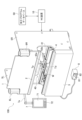
- FIG. 1 is a diagram illustrating the overall configuration of a press brake according to one or more embodiments.
- FIG. 2 is a diagram illustrating an example configuration of an angle sensor included in a press brake according to one or more embodiments.
- FIG. 3 is a diagram showing the angle of the metal plate detected by the angle sensor shown in FIG.
- FIG. 4 is a diagram illustrating a first example of a control operation by an NC device provided in a press brake according to one or more embodiments.
- FIG. 5 is a diagram illustrating a second example of a control operation by an NC device provided in a press brake according to one or more embodiments.
- FIG. 6 is a diagram illustrating a third example of a control operation by an NC device provided in a press brake according to one or more embodiments.
- FIG. 7 is a flowchart illustrating operation of a press brake in accordance with one or more embodiments and a method of controlling a press brake in accordance with one or more embodiments.
- the press brake includes an upper table, a lower table, a table lifting mechanism, an angle sensor, and a control device.
- a punch is attached to the upper table, and a die is attached to the lower table.
- the table lifting mechanism raises and lowers the upper table or the lower table.
- the angle sensor measures the angle of the metal sheet when the upper table or the lower table is raised and lowered by the table lifting mechanism to bend the metal sheet while the metal sheet is sandwiched between the punch and the die.
- the control device calculates the bending angle of the metal sheet based on the angle of the metal sheet measured by the angle sensor, and controls the raising and lowering of the upper table or the lower table by the table lifting mechanism.
- the control device controls the elevation of the upper table to bend the metal sheet to the target bend angle as follows: During the pre-bending period, the control device controls the table elevation mechanism to lower the upper table by a first depth value or raise the lower table by the first depth value to bend the metal sheet to a predetermined pre-bend angle wider than the target bend angle. The control device calculates the first bend angle of the metal sheet bent to the pre-bend angle based on the angle of the metal sheet measured by the angle sensor.
- the control device controls the table lifting mechanism to raise the upper table or lower the lower table so as to unload the sheet metal while maintaining the punch in contact with the sheet metal during the unloading period after the sheet metal has been bent to the provisional bend angle.
- the control device calculates a second bend angle of the sheet metal based on the angle of the sheet metal measured by the angle sensor, and calculates the amount of springback based on the difference between the second bend angle and the first bend angle.
- the control device calculates a second depth value during the push-in period that takes into account the amount of springback required to bend the sheet metal to the target bend angle, and controls the table lifting mechanism to lower the upper table by the second depth value or raise the lower table by the second depth value.
- the control device controls the table lifting mechanism to raise the upper table or lower the lower table so as to unload the sheet metal while maintaining the punch in contact with the sheet metal, and calculates the final bend angle of the sheet metal based on the angle of the sheet metal measured by the angle sensor.
- a control device controls a press brake having an upper table on which a punch is attached, a lower table on which a die is attached, a table lifting mechanism for raising and lowering the upper table or the lower table, and an angle sensor for measuring the angle of the metal sheet being bent by being sandwiched between the punch and the die, as follows:
- the control device controls the table lifting mechanism to lower the upper table by a first depth value or to raise the lower table by the first depth value during the pre-bending period so as to bend the metal sheet to a predetermined pre-bending angle that is wider than the target bend angle.
- the control device calculates a first bending angle of the metal sheet bent to the pre-bending angle based on the angle of the metal sheet measured by the angle sensor.
- the control device controls the table lifting mechanism to raise the upper table or lower the lower table so as to unload the sheet metal while maintaining the punch in contact with the sheet metal during the unloading period after the sheet metal has been bent to the provisional bend angle.
- the control device calculates a second bend angle of the sheet metal based on the angle of the sheet metal measured by the angle sensor, and calculates a springback amount based on the difference between the second bend angle and the first bend angle.
- the control device calculates a second depth value during the push-in period that takes into account the amount of springback required to bend the sheet metal to the target bend angle, and controls the table lifting mechanism to lower the upper table by the second depth value or raise the lower table by the second depth value.
- the control device controls the table lifting mechanism to raise the upper table or lower the lower table so as to unload the sheet metal while maintaining the punch in contact with the sheet metal, and calculates the final bend angle of the sheet metal based on the angle of the sheet metal measured by the angle sensor.
- FIG. 1 shows the overall configuration of a press brake 100 according to one or more embodiments.
- the press brake 100 is equipped with an NC (Numerical Control) device 10 that functions as a control device for controlling the press brake 100.
- a processing program database 50 is connected to the NC device 10 via a network.
- the press brake 100 is equipped with an upper table 1, a lower table 3, and left and right side plates 5R and 5L.
- An upper die holder 2 is attached to the upper table 1, and a lower die holder 4 is attached to the lower table 3.
- the upper table 1 is configured to be raised and lowered by hydraulic cylinders 6L and 6R provided on the left and right sides.
- the hydraulic cylinders 6L and 6R are referred to as the table lifting mechanism 6.
- the table lifting mechanism 6 may include actuators other than the hydraulic cylinders 6L and 6R. The table lifting mechanism 6 lowers the upper table 1 so that it is closer to the lower table 3, and raises it so that it is away from the lower table 3.
- the upper die holder 2 is fitted with a punch Tp, which is an upper die
- the lower die holder 4 is fitted with a die Td, which is a lower die.
- a modular type is shown in which the upper die holder 2 is integrally attached over the entire length of the lower end of the upper table 1, but it may also be an intermediate plate type in which multiple intermediate plates for mounting punches Tp are attached in the longitudinal direction of the lower end of the upper table 1.
- the intermediate plates are also upper die holders.
- Attaching a punch Tp to the upper table 1 means attaching the punch Tp to the upper die holder 2 or the intermediate plate.
- Attaching a die Td to the lower table 3 means attaching the die Td to the lower die holder 4. Two or more punches Tp may be attached side by side to the upper table 1, and two or more dies Td may be attached side by side to the lower table 3.
- a back gauge 40 is disposed on the rear side of the lower table 3.
- the back gauge 40 has stoppers 42a and 42b that move left and right along the back gauge carriage 41.
- stoppers 42a and 42b there are two stoppers, stoppers 42a and 42b, but the number of stoppers is not limited to two. Stoppers 42a and 42b are configured to move in the height direction and the front and rear directions as well.
- the butts 42a and 42b move to a position corresponding to the die Td.
- the operator places the back end of the metal sheet W on the die Td so that it butts against the butts 42a and 42b.
- the butts 42a and 42b act to determine the front-to-rear position of the metal sheet W when it is placed on the die Td.
- An operation pendant 7 having a display unit 71 and an operation unit 72 including multiple operation buttons is attached via an arm 7a to the left side of the press brake 100.
- the operation pendant 7 is connected to the NC device 10.
- a foot switch 8 having a close foot switch 81 that lowers the upper table 1 and an open foot switch 82 that raises the upper table 1 is connected to the NC device 10.
- FIG. 2 shows an example of the configuration of the angle sensor equipped in the press brake 100.
- the press brake 100 is equipped with angle sensors 21F and 21R that measure the angle of the metal sheet W when bending the metal sheet W.
- the angle sensor 21F is disposed on the front side of the die Td
- the angle sensor 21R is disposed on the rear side of the die Td.
- the angle sensors 21F and 21R are so-called contact-type angle sensors.
- the angle sensors 21F and 21R are configured to be raised and lowered by the sensor lifting mechanisms 22F and 22R, respectively.
- the angle sensors 21F and 21R located at the bottom are moved upward by the sensor lifting mechanisms 22F and 22R in accordance with the control of the NC device 10.
- Angle sensors 21F and 21R have a main body 211 and a protruding portion 212 that can be freely extended and retracted from the main body 211.
- a slightly protruding tip 213 is provided at the upper end of the protruding portion 212.
- the protruding portions 212 of angle sensors 21F and 21R are in a state where they are least protruding.
- FIG. 3 shows the angle of the metal sheet W detected by angle sensors 21F and 21R. As shown in FIG. 3, when punch Tp descends and the metal sheet W is bent, protruding portion 212 protrudes upward as the metal sheet W is displaced upward.
- the angle of the sheet metal W measured by the angle sensor 21F is the angle ⁇ F between the reference plane, which is the surface indicated by the dashed line extending from the upper end face of the die Td, and the part of the sheet metal W forward of the punch Tp and the die Td.
- the angle of the sheet metal W measured by the angle sensor 21R is the angle ⁇ R between the reference plane and the part of the sheet metal W rearward of the punch Tp and the die Td.
- the angles ⁇ F and ⁇ R measured by the angle sensors 21F and 21R are input to the NC device 10.
- the NC device 10 calculates the bending angle ⁇ of the sheet metal W shown in FIG. 3 using the formula 180- ⁇ F- ⁇ R.
- the angle sensor that measures the angle of the metal sheet W is not limited to a contact angle sensor, and may be a laser angle sensor.
- the sensor lifting mechanisms 22F and 22R are not necessary, and the front and rear laser angle sensors are at fixed positions in the height direction.
- the front and rear laser angle sensors have a laser emission unit that irradiates linear laser light onto the portion of the metal sheet W forward and rearward of the punch Tp and die Td, and an imaging unit that captures the linear laser light irradiated onto the metal sheet W.
- the NC device 10 determines the angles of the metal sheet W equivalent to the angles ⁇ F and ⁇ R based on the angle of the linear laser light in the image captured by the imaging unit, and calculates the bending angle ⁇ of the metal sheet W.
- the NC device 10 controls the press brake 100 to bend the metal sheet W using the control operations of the first to third examples according to the processing program.
- Figure 4 shows a first example of the control operation by the NC device 10.
- the horizontal axis indicates time
- the vertical axis indicates the height position of the tip of the punch Tp.
- the area between positions R3 and F3 is shown in an enlarged state to make it easier to understand the change in the height position of the tip of the punch Tp.
- the distance from position R3 to position F3 is approximately 0.1 mm to 0.2 mm.
- the distance from the contact position described below to position F3 is approximately 2 mm to 3 mm.
- the target bending angle of the metal sheet W is, for example, 90 degrees.
- the NC device 10 controls the raising and lowering of the upper table 1 as shown in FIG. 4 so as to bend the metal sheet W to the target bending angle of 90 degrees.
- the tip of the punch Tp comes into contact with the metal sheet W.
- the NC device 10 stops the upper table 1 with the tip of the punch Tp positioned at the contact position in FIG. 4, and moves the abutments 42a and 42b away from the metal sheet W.
- the NC device 10 lowers the position of the tip of the punch Tp to position T1, stops it temporarily, and then lowers it further to position T2.
- the upper table 1 (punch Tp) is lowered in two stages, but the number of stages of descent is not limited to two.
- Position T2 during the pre-bending period is a position for bending the sheet metal W to a predetermined pre-bending angle that is wider than the target bending angle of 90 degrees.
- the NC device 10 controls the table lifting mechanism 6 to lower the upper table 1 by a first depth value for bending the sheet metal W to the pre-bending angle.
- the first depth value of the punch Tp for bending the sheet metal W to the pre-bending angle after the tip of the punch Tp comes into contact with the sheet metal W is determined in advance based on bending theory.
- the depth value is the amount of descent of the punch Tp when the contact position where the tip of the punch Tp comes into contact with the sheet metal W is used as the reference. In other words, the depth value indicates the height direction position of the tip of the punch Tp.
- the depth value is abbreviated as D value.
- the NC device 10 calculates the first bending angle ⁇ 1 of the metal sheet W based on the angle of the metal sheet W measured by the angle sensors 21F and 21R. The NC device 10 holds the first bending angle ⁇ 1 at the time when the pre-bending operation of the metal sheet W is completed.
- the NC device 10 transitions the press brake 100 to an unloading period.
- the NC device 10 controls the upper table 1 to rise in succession in multiple stages so as to unload the metal sheet W while maintaining the punch Tp in contact with the metal sheet W.
- Unloading refers to removing the load applied to the metal sheet W.
- the NC device 10 raises the tip of the punch Tp to position R1 and stops it temporarily, and calculates the bending angle of the sheet metal W based on the angle of the sheet metal W measured by the angle sensors 21F and 21R.
- the NC device 10 raises the tip of the punch Tp to position R2 and stops it temporarily, and calculates the bending angle of the sheet metal W.
- the difference between the bending angle at position R1 and the bending angle at position R2 is within a threshold value, the unloading of the sheet metal W is completed.
- FIG. 4 shows an example in which the unloading of the sheet metal W is not completed at position R2.
- the NC device 10 raises the tip of the punch Tp to position R3 and stops it temporarily, and calculates the bending angle of the sheet metal W.
- the difference between the bending angle at position R2 and the bending angle at position R3 is within a threshold value, and the unloading of the sheet metal W is completed at position R3.
- the number of stages in which the unloading of the metal sheet W is completed varies depending on various conditions, such as the distance from position T2 to position R1 and the distance from position R1 to position R2.
- positions R1, R2, and R3 are spaced relatively long apart to form coarse stages, but the distance by which the position of the tip of the punch Tp is raised at one time may be set finely to form fine stages.
- the NC device 10 continuously repeats the process of calculating the bending angle of the metal sheet W by raising the position of the tip of the punch Tp by a fine distance. If the fine distance is a constant distance, the position of the tip of the punch Tp rises in a substantially linear manner, strictly speaking in a fine step-like manner, while the bending angle of the metal sheet W is calculated at each point in time.
- the NC device 10 calculates the second bending angle ⁇ 2 of the metal sheet W based on the angle of the metal sheet W measured by the angle sensors 21F and 21R. Even if the metal sheet W is bent to the first bending angle ⁇ 1 during the provisional bending period, when the metal sheet W is unloaded during the unloading period, the bending angle widens due to springback.
- the second bending angle ⁇ 2 is the bending angle of the metal sheet W that has widened due to springback.
- the NC device 10 calculates the amount of springback by subtracting the first bending angle ⁇ 1 from the second bending angle ⁇ 2.
- the NC device 10 transitions the press brake 100 to the push-in period.
- the NC device 10 calculates a second D value that takes into account the springback amount for bending the metal sheet W to the target bending angle.
- the springback amount is, for example, 2 degrees
- the springback amount generally differs depending on the target bending angle, even if the target bending angle is set using the springback amount obtained during the unloading period as is, the target bending angle may not be 90 degrees.
- the NC device 10 should correct the springback amount obtained during the unloading period and then calculate a second D value for bending the metal sheet W to the set target bending angle.
- the NC device 10 divides the second D value into multiple parts and controls the table lifting mechanism 6 to sequentially lower the upper table 1 by the second D value in multiple stages.
- the NC device 10 lowers the tip of the punch Tp from position R3 to position F1, stops it temporarily, and calculates the bending angle of the sheet metal W based on the angle of the sheet metal W.
- the NC device 10 lowers the tip of the punch Tp to position F2, taking into account the bending angle at position F1, and stops it temporarily, and calculates the bending angle of the sheet metal W based on the angle of the sheet metal W.
- the NC device 10 lowers the tip of the punch Tp to position F3, where the final bending angle of the sheet metal W is the target bending angle of 90 degrees, taking into account the bending angle at position F2.
- the push-up operation during the push-up period is described as having three stages, but it may also be one stage, two stages, or four or more stages.
- the stages of the push-up operation are not limited.
- the NC device 10 transitions the press brake 100 to the final angle measurement period.
- the NC device 10 unloads the metal sheet W while maintaining the state in which the punch Tp is in contact with the metal sheet W, and calculates the final bending angle of the metal sheet W based on the angle of the metal sheet W measured by the angle sensors 21F and 21R.
- the NC device 10 raises the tip of the punch Tp to position L1, stops it, and calculates the bending angle of the metal sheet W.
- the NC device 10 raises the tip of the punch Tp to position L2, stops it, and calculates the bending angle of the metal sheet W.
- the unloading of the metal sheet W is completed.
- the unloading of the metal sheet W is completed at position L2.
- the NC device 10 calculates the final bending angle of the metal sheet W.
- the NC device 10 controls the table lifting mechanism 6 to raise the upper table 1.
- the amount of lift of the upper table 1 from position T2 of the tip of the punch Tp at the end of the pre-bending period to position R2, which is an intermediate stage before position R3 where the unloading of the metal sheet W is complete, is set as U2.
- the amount of lift U2 is set as the amount of lift of the upper table 1 at the beginning of the final angle measurement period, which is the amount of lift from position F3 of the tip of the punch Tp at the end of the drive-in period to position L1.
- the final bending angle of the metal sheet W is calculated by the angle sensors 21F and 21R after the end of the push-in period, so there is no need for the operator to measure the final bending angle with a digital bending angle meter.
- the lift amount U2 by which the upper table 1 is raised in order to unload the metal sheet W up to an intermediate stage before unloading is completed during the unloading period is set to the initial lift amount of the upper table 1 during the final angle measurement period. Therefore, according to the first example, the time required for unloading during the final angle measurement period can be shortened.
- FIG. 5 shows a second example of the control operation by the NC device 10.
- the same parts as in FIG. 4 are given the same reference numerals, and their description will be omitted.
- the upper table 1 is lowered in two stages during the pre-bending period, and in three stages during the push-in period.
- unloading is completed in three stages during the unloading period, and in two stages during the final angle measurement period, and the upper table 1 is raised.
- the amount of lift of the upper table 1 from position T2 of the tip of the punch Tp at the end of the provisional bending period to position R3 where the unloading of the metal sheet W is complete is designated as U3.
- the amount of lift obtained by multiplying the amount of lift U3 by a predetermined coefficient k less than 1 is set as the initial amount of lift of the upper table 1 in the final angle measurement period.
- the NC device 10 calculates the final bending angle of the metal sheet W, and then controls the table lifting mechanism 6 to lift the upper table 1. According to the second example, the time required for unloading in the final angle measurement period can be shortened.
- FIG. 6 shows a third example of the control operation by the NC device 10.
- the same parts as in FIG. 4 are given the same reference numerals, and their explanation will be omitted.
- the upper table 1 is lowered in two stages during the pre-bending period, and in three stages during the push-in period.
- unloading is completed in three stages during the unloading period, and unloading of the metal sheet W is completed in one stage during the final angle measurement period, and the upper table 1 is raised.
- the amount of lift U3 of the upper table 1 from the position T2 of the tip of the punch Tp at the end of the pre-bending period to the position R3 where the unloading of the metal sheet W is complete is set as the amount of lift by which the upper table 1 is raised in order to unload the metal sheet W in one stage during the final angle measurement period.
- the NC device 10 calculates the final bending angle of the metal sheet W, and then controls the table lifting mechanism 6 to lift the upper table 1. According to the third example, the time required for unloading during the final angle measurement period can be shortened.
- the amount of lift of the upper table 1 up to an intermediate stage before the unloading of the metal sheet W is completed during the unloading period, or the amount of lift of the upper table 1 until the unloading of the metal sheet W is completed, is reflected in the amount of lift of the upper table 1 during the final angle measurement period. Therefore, the time required for unloading during the final angle measurement period can be shortened, and therefore the processing time from the start of bending the metal sheet W to checking the bending angle after the bending is completed can be shortened.
- the NC device 10 controls the table lifting mechanism 6 to lower the upper table 1 by a first D value in step S1 so as to bend the metal sheet W to a predetermined provisional bending angle that is wider than the target bending angle.
- step S2 the NC device 10 calculates the first bending angle ⁇ 1 of the metal sheet W.
- step S3 the NC device 10 controls the table lifting mechanism 6 to raise the upper table 1 until unloading of the metal sheet W is complete.
- step S4 the NC device 10 calculates the second bending angle ⁇ 2 of the metal sheet W.
- step S5 the NC device 10 calculates the amount of springback based on the difference between the second bending angle ⁇ 2 and the first bending angle ⁇ 1.
- step S6 the NC device 10 calculates a second D value for the upper table 1 to bend the metal sheet W to the target bending angle, taking into account the amount of springback.
- step S7 the NC device 10 controls the table lifting mechanism 6 to lower the upper table 1 in one or more stages based on the second D value and bend the metal sheet W to the target bending angle.
- step S8 the NC device 10 raises the upper table 1 until the unloading of the metal sheet W is complete, and then calculates the final bending angle of the metal sheet W.
- step S9 the NC device 10 raises the upper table 1 to end the bending process.
- the process shown in FIG. 7 is performed for each metal sheet W when bending multiple metal sheets W in sequence. Therefore, when bending each metal sheet W, it is possible to check whether the metal sheet W is actually bent to the target bending angle.
- the present invention is not limited to the one or more embodiments described above, and various modifications are possible without departing from the gist of the present invention.
- the upper table 1 is a slide table that can be raised and lowered
- the lower table 3 is a fixed table whose position is fixed, but it is also possible for the upper table 1 to be a fixed table and the lower table 3 to be a slide table.
- the table lifting mechanism 6 raises and lowers the lower table 3.
- the rise and fall of the upper table 1 can be interpreted as the fall and rise of the lower table 3, respectively, and the first and second amounts of descent of the upper table 1 can be interpreted as the first and second amounts of rise of the lower table 3.
- the D value is the amount of descent of the punch Tp when the contact position of the tip of the punch Tp is used as the reference point, but the D value may also be the distance between the tip of the die Td and the tip of the punch Tp when the position of the tip of the die Td is used as the reference point. Even in this case, the D value indicates the height position of the tip of the punch Tp.
Landscapes
- Engineering & Computer Science (AREA)
- Mechanical Engineering (AREA)
- Physics & Mathematics (AREA)
- General Physics & Mathematics (AREA)
- Bending Of Plates, Rods, And Pipes (AREA)
Abstract
Description
Claims (10)
- パンチを装着する上部テーブルと、
ダイを装着する下部テーブルと、
前記上部テーブルまたは前記下部テーブルを昇降させるテーブル昇降機構と、
板金を前記パンチと前記ダイとで挟んだ状態で、前記テーブル昇降機構によって前記上部テーブルまたは前記下部テーブルを昇降させて前記板金を曲げるときの前記板金の角度を計測する角度センサと、
前記角度センサが計測した前記板金の角度に基づいて前記板金の曲げ角度を算出し、前記テーブル昇降機構による前記上部テーブルまたは前記下部テーブルの昇降を制御する制御装置と、
を備え、
前記制御装置は、
前記板金を目標曲げ角度に曲げるよう前記上部テーブルまたは前記下部テーブルの昇降を制御するとき、
仮曲げ期間において、前記板金を前記目標曲げ角度よりも広い所定の仮曲げ角度に曲げるよう、前記上部テーブルを第1のデプス値だけ下降させるか前記下部テーブルを前記第1のデプス値だけ上昇させるよう前記テーブル昇降機構を制御し、
前記角度センサが計測した前記板金の角度に基づいて、前記仮曲げ角度に曲げられた前記板金の第1の曲げ角度を算出し、
前記板金が前記仮曲げ角度に曲げられた後の除荷期間において、前記パンチが前記板金に接触している状態を維持しつつ前記板金を除荷するよう、前記上部テーブルを上昇させるか前記下部テーブルを下降させるよう前記テーブル昇降機構を制御し、
前記除荷期間において前記板金が除荷された状態で、前記角度センサが計測した前記板金の角度に基づいて前記板金の第2の曲げ角度を算出して、前記第2の曲げ角度と前記第1の曲げ角度との差分に基づくスプリングバック量を算出し、
追い込み期間において、前記板金を前記目標曲げ角度に曲げるための前記スプリングバック量を考慮した第2のデプス値を算出して、前記上部テーブルを前記第2のデプス値だけ下降させるか前記下部テーブルを前記第2のデプス値だけ上昇させるよう前記テーブル昇降機構を制御し、
前記板金が前記目標曲げ角度に曲げられた後の最終角度計測期間において、前記パンチが前記板金に接触している状態を維持しつつ前記板金を除荷するよう、前記上部テーブルを上昇させるか前記下部テーブルを下降させるよう前記テーブル昇降機構を制御して、前記角度センサが計測した前記板金の角度に基づいて前記板金の最終的な曲げ角度を算出する
プレスブレーキ。 - 前記制御装置は、前記除荷期間において、前記板金の除荷が完了する前の途中の段階までの除荷のために前記上部テーブルを上昇させる上昇量もしくは前記下部テーブルを下降させる下降量、または前記板金の除荷が完了するまで前記上部テーブルを上昇させる上昇量もしくは前記下部テーブルを下降させる下降量に基づいて、前記最終角度計測期間において前記板金を除荷するために前記上部テーブルを上昇させる上昇量または前記下部テーブルを下降させる下降量を設定する請求項1に記載のプレスブレーキ。
- 前記制御装置は、前記除荷期間において前記板金の除荷が完了する前の途中の段階までの除荷のために前記上部テーブルを上昇させる上昇量または前記下部テーブルを下降させる下降量を、前記最終角度計測期間において前記板金を除荷するために前記上部テーブルを上昇させる最初の上昇量または前記下部テーブルを下降させる最初の下降量として設定する請求項2に記載のプレスブレーキ。
- 前記制御装置は、前記除荷期間において前記板金の除荷が完了するまで前記上部テーブルを上昇させる上昇量に1未満の所定の係数を乗算した上昇量または前記下部テーブルを下降させる下降量に1未満の所定の係数を乗算した下降量を、前記最終角度計測期間において前記板金を除荷するために前記上部テーブルを上昇させる最初の上昇量または前記下部テーブルを下降させる最初の下降量として設定する請求項2に記載のプレスブレーキ。
- 前記制御装置は、前記除荷期間において前記板金の除荷が完了するまで前記上部テーブルを上昇させる上昇量または前記下部テーブルを下降させる下降量を、前記最終角度計測期間において前記板金を1段階で除荷するために前記上部テーブルを上昇させる上昇量または前記下部テーブルを下降させる下降量として設定する請求項2に記載のプレスブレーキ。
- パンチを装着する上部テーブルと、ダイを装着する下部テーブルと、前記上部テーブルまたは前記下部テーブルを昇降させるテーブル昇降機構と、前記パンチと前記ダイとで挟まれて曲げられる板金の角度を計測する角度センサとを備えるプレスブレーキを制御する制御装置が、
仮曲げ期間において、前記板金を目標曲げ角度よりも広い所定の仮曲げ角度に曲げるよう、前記上部テーブルを第1のデプス値だけ下降させるか前記下部テーブルを前記第1のデプス値だけ上昇させるよう前記テーブル昇降機構を制御し、
前記角度センサが計測した前記板金の角度に基づいて、前記仮曲げ角度に曲げられた前記板金の第1の曲げ角度を算出し、
前記板金が前記仮曲げ角度に曲げられた後の除荷期間において、前記パンチが前記板金に接触している状態を維持しつつ前記板金を除荷するよう、前記上部テーブルを上昇させるか前記下部テーブルを下降させるよう前記テーブル昇降機構を制御し、
前記除荷期間において前記板金が除荷された状態で、前記角度センサが計測した前記板金の角度に基づいて前記板金の第2の曲げ角度を算出して、前記第2の曲げ角度と前記第1の曲げ角度との差分に基づくスプリングバック量を算出し、
追い込み期間において、前記板金を前記目標曲げ角度に曲げるための前記スプリングバック量を考慮した第2のデプス値を算出して、前記上部テーブルを第2のデプス値だけ下降させるか前記下部テーブルを前記第2のデプス値だけ上昇させるよう前記テーブル昇降機構を制御し、
前記板金が前記目標曲げ角度に曲げられた後の最終角度計測期間において、前記パンチが前記板金に接触している状態を維持しつつ前記板金を除荷するよう、前記上部テーブルを上昇させるか前記下部テーブルを下降させるよう記テーブル昇降機構を制御して、前記角度センサが計測した前記板金の角度に基づいて前記板金の最終的な曲げ角度を算出する
プレスブレーキ制御方法。 - 前記制御装置が、前記除荷期間において、前記板金の除荷が完了する前の途中の段階までの除荷のために前記上部テーブルを上昇させる上昇量もしくは前記下部テーブルを下降させる下降量、または前記板金の除荷が完了するまで前記上部テーブルを上昇させる上昇量もしくは前記下部テーブルを下降させる下降量に基づいて、前記最終角度計測期間において前記板金を除荷するために前記上部テーブルを上昇させる上昇量または前記下部テーブルを下降させる下降量を設定する請求項6に記載のプレスブレーキ制御方法。
- 前記除荷期間において前記板金の除荷が完了する前の途中の段階までの除荷のために前記上部テーブルを上昇させる上昇量または前記下部テーブルを下降させる下降量を、前記最終角度計測期間において前記板金を除荷するために前記上部テーブルを上昇させる最初の上昇量または前記下部テーブルを下降させる最初の下降量として設定する請求項7に記載のプレスブレーキ制御方法。
- 前記制御装置が、前記除荷期間において前記板金の除荷が完了するまで前記上部テーブルを上昇させる上昇量に1未満の所定の係数を乗算した上昇量または前記下部テーブルを下降させる下降量に1未満の所定の係数を乗算した下降量を、前記最終角度計測期間において前記板金を除荷するために前記上部テーブルを上昇させる最初の上昇量または前記下部テーブルを下降させる最初の下降量として設定する請求項7に記載のプレスブレーキ制御方法。
- 前記制御装置が、前記除荷期間において前記板金の除荷が完了するまで前記上部テーブルを上昇させる上昇量または前記下部テーブルを下降させる下降量を、前記最終角度計測期間において前記板金を1段階で除荷するために前記上部テーブルを上昇させる上昇量または前記下部テーブルを下降させる下降量として設定する請求項7に記載のプレスブレーキ制御方法。
Priority Applications (1)
| Application Number | Priority Date | Filing Date | Title |
|---|---|---|---|
| EP23879719.5A EP4606498A4 (en) | 2022-10-21 | 2023-10-13 | PRESS BRAKE AND PRESS BRAKE CONTROL METHOD |
Applications Claiming Priority (2)
| Application Number | Priority Date | Filing Date | Title |
|---|---|---|---|
| JP2022169329A JP7433398B1 (ja) | 2022-10-21 | 2022-10-21 | プレスブレーキ及びプレスブレーキ制御方法 |
| JP2022-169329 | 2022-10-21 |
Publications (1)
| Publication Number | Publication Date |
|---|---|
| WO2024085076A1 true WO2024085076A1 (ja) | 2024-04-25 |
Family
ID=89904329
Family Applications (1)
| Application Number | Title | Priority Date | Filing Date |
|---|---|---|---|
| PCT/JP2023/037146 Ceased WO2024085076A1 (ja) | 2022-10-21 | 2023-10-13 | プレスブレーキ及びプレスブレーキ制御方法 |
Country Status (3)
| Country | Link |
|---|---|
| EP (1) | EP4606498A4 (ja) |
| JP (1) | JP7433398B1 (ja) |
| WO (1) | WO2024085076A1 (ja) |
Families Citing this family (1)
| Publication number | Priority date | Publication date | Assignee | Title |
|---|---|---|---|---|
| JP7664435B1 (ja) * | 2024-01-09 | 2025-04-17 | 株式会社アマダ | プレスブレーキ及びプレスブレーキ制御方法 |
Citations (6)
| Publication number | Priority date | Publication date | Assignee | Title |
|---|---|---|---|---|
| JP2004202545A (ja) * | 2002-12-25 | 2004-07-22 | Amada Co Ltd | ワーク折曲げ加工方法及び装置 |
| JP4280332B2 (ja) | 1998-08-14 | 2009-06-17 | 株式会社アマダ電子 | 曲げ加工機における曲げ角度測定方法およびその装置 |
| JP2013180339A (ja) * | 2012-03-05 | 2013-09-12 | Amada Co Ltd | プレスブレーキおよびワークの曲げ加工方法 |
| JP2015221447A (ja) * | 2014-05-22 | 2015-12-10 | 株式会社アマダホールディングス | 折曲げ角度検出方法及び装置 |
| JP2016196044A (ja) * | 2016-07-04 | 2016-11-24 | 株式会社アマダホールディングス | 金型 |
| JP2022169329A (ja) | 2021-04-27 | 2022-11-09 | 株式会社ダイフク | 検査システム |
Family Cites Families (3)
| Publication number | Priority date | Publication date | Assignee | Title |
|---|---|---|---|---|
| JP4280333B2 (ja) * | 1998-08-14 | 2009-06-17 | 株式会社アマダ電子 | 曲げ加工機における曲げ角度制御方法およびその装置 |
| JP3415080B2 (ja) * | 1999-07-01 | 2003-06-09 | 村田機械株式会社 | 曲げ機械およびその運転方法 |
| AT518993B1 (de) * | 2016-11-18 | 2018-03-15 | Trumpf Maschinen Austria Gmbh & Co Kg | Verfahren zum Betrieb einer Biegemaschine |
-
2022
- 2022-10-21 JP JP2022169329A patent/JP7433398B1/ja active Active
-
2023
- 2023-10-13 WO PCT/JP2023/037146 patent/WO2024085076A1/ja not_active Ceased
- 2023-10-13 EP EP23879719.5A patent/EP4606498A4/en active Pending
Patent Citations (6)
| Publication number | Priority date | Publication date | Assignee | Title |
|---|---|---|---|---|
| JP4280332B2 (ja) | 1998-08-14 | 2009-06-17 | 株式会社アマダ電子 | 曲げ加工機における曲げ角度測定方法およびその装置 |
| JP2004202545A (ja) * | 2002-12-25 | 2004-07-22 | Amada Co Ltd | ワーク折曲げ加工方法及び装置 |
| JP2013180339A (ja) * | 2012-03-05 | 2013-09-12 | Amada Co Ltd | プレスブレーキおよびワークの曲げ加工方法 |
| JP2015221447A (ja) * | 2014-05-22 | 2015-12-10 | 株式会社アマダホールディングス | 折曲げ角度検出方法及び装置 |
| JP2016196044A (ja) * | 2016-07-04 | 2016-11-24 | 株式会社アマダホールディングス | 金型 |
| JP2022169329A (ja) | 2021-04-27 | 2022-11-09 | 株式会社ダイフク | 検査システム |
Non-Patent Citations (1)
| Title |
|---|
| See also references of EP4606498A4 |
Also Published As
| Publication number | Publication date |
|---|---|
| JP7433398B1 (ja) | 2024-02-19 |
| EP4606498A1 (en) | 2025-08-27 |
| EP4606498A4 (en) | 2026-02-18 |
| JP2024061399A (ja) | 2024-05-07 |
Similar Documents
| Publication | Publication Date | Title |
|---|---|---|
| JP3559288B2 (ja) | 工作物を折り曲げるための方法及び加工機械 | |
| JP4050619B2 (ja) | プレスブレーキのストロークを調整する方法 | |
| WO2024085076A1 (ja) | プレスブレーキ及びプレスブレーキ制御方法 | |
| US20070266752A1 (en) | System for Metering the Bending Angle in a Machine for Bending Metallic Sheets and/or Sections, as Well as Method and Machine for Bending Metallic Sheets and/or Sections Using Such System | |
| JP2019537515A (ja) | 曲げ機械を駆動する方法 | |
| JP7433506B1 (ja) | プレスブレーキ及びプレスブレーキ制御方法 | |
| WO2001053018A1 (fr) | Procede de detection de l'epaisseur de toles, et dispositif a cet effet d'une plieuse, procede de detection de la distance entre lames de reference, procede de pliage et dispositif de pliage | |
| WO2025150376A1 (ja) | プレスブレーキ及びプレスブレーキ制御方法 | |
| JPH04251614A (ja) | プレスブレーキ | |
| JP6477541B2 (ja) | 鋼板形状矯正方法および鋼板製造方法 | |
| EP3991867A1 (en) | Press brake | |
| EP4032630B1 (en) | Bending method and bending system | |
| JP7485927B2 (ja) | プレス矯正システム、出力制御装置、プレス矯正方法及びプログラム | |
| JP2024122486A (ja) | プレスブレーキ、および曲げ加工方法 | |
| JPH01271013A (ja) | プレスブレーキの折曲げ角度制御装置 | |
| JP6889049B2 (ja) | プレスブレーキ、および曲げ加工方法 | |
| JPS6352715A (ja) | 曲げ機械 | |
| JP7821914B1 (ja) | 曲げ角度測定装置及び曲げ角度測定方法 | |
| JP7675539B2 (ja) | 曲げ加工方法及び曲げ加工システム | |
| JP2000246342A (ja) | 曲げ加工機およびこの曲げ加工機を用いた曲げ加工方法 | |
| JP4436224B2 (ja) | プレス成形方法及びプレス成形装置 | |
| JP2005219113A (ja) | プレス成形方法およびプレス成形装置 | |
| JPH02280919A (ja) | 折曲げ加工機 | |
| JPH0985350A (ja) | 折曲げ加工機における曲げ加工方法およびこの方法を用いた折曲げ加工機 | |
| JP2020192537A (ja) | 曲げ戻し方法および曲げ戻し装置 |
Legal Events
| Date | Code | Title | Description |
|---|---|---|---|
| 121 | Ep: the epo has been informed by wipo that ep was designated in this application |
Ref document number: 23879719 Country of ref document: EP Kind code of ref document: A1 |
|
| WWE | Wipo information: entry into national phase |
Ref document number: 2023879719 Country of ref document: EP |
|
| NENP | Non-entry into the national phase |
Ref country code: DE |
|
| ENP | Entry into the national phase |
Ref document number: 2023879719 Country of ref document: EP Effective date: 20250521 |
|
| WWP | Wipo information: published in national office |
Ref document number: 2023879719 Country of ref document: EP |