WO2024105902A1 - ファン装置 - Google Patents
ファン装置 Download PDFInfo
- Publication number
- WO2024105902A1 WO2024105902A1 PCT/JP2023/018230 JP2023018230W WO2024105902A1 WO 2024105902 A1 WO2024105902 A1 WO 2024105902A1 JP 2023018230 W JP2023018230 W JP 2023018230W WO 2024105902 A1 WO2024105902 A1 WO 2024105902A1
- Authority
- WO
- WIPO (PCT)
- Prior art keywords
- motor
- fan
- heat shield
- fan device
- motor support
- Prior art date
- Legal status (The legal status is an assumption and is not a legal conclusion. Google has not performed a legal analysis and makes no representation as to the accuracy of the status listed.)
- Ceased
Links
Images




Classifications
-
- F—MECHANICAL ENGINEERING; LIGHTING; HEATING; WEAPONS; BLASTING
- F04—POSITIVE - DISPLACEMENT MACHINES FOR LIQUIDS; PUMPS FOR LIQUIDS OR ELASTIC FLUIDS
- F04D—NON-POSITIVE-DISPLACEMENT PUMPS
- F04D29/00—Details, component parts, or accessories
- F04D29/40—Casings; Connections of working fluid
- F04D29/52—Casings; Connections of working fluid for axial pumps
- F04D29/54—Fluid-guiding means, e.g. diffusers
- F04D29/541—Specially adapted for elastic fluid pumps
-
- F—MECHANICAL ENGINEERING; LIGHTING; HEATING; WEAPONS; BLASTING
- F01—MACHINES OR ENGINES IN GENERAL; ENGINE PLANTS IN GENERAL; STEAM ENGINES
- F01P—COOLING OF MACHINES OR ENGINES IN GENERAL; COOLING OF INTERNAL-COMBUSTION ENGINES
- F01P11/00—Component parts, details, or accessories not provided for in, or of interest apart from, groups F01P1/00 - F01P9/00
- F01P11/10—Guiding or ducting cooling-air, to, or from, liquid-to-air heat exchangers
-
- F—MECHANICAL ENGINEERING; LIGHTING; HEATING; WEAPONS; BLASTING
- F01—MACHINES OR ENGINES IN GENERAL; ENGINE PLANTS IN GENERAL; STEAM ENGINES
- F01P—COOLING OF MACHINES OR ENGINES IN GENERAL; COOLING OF INTERNAL-COMBUSTION ENGINES
- F01P5/00—Pumping cooling-air or liquid coolants
- F01P5/02—Pumping cooling-air; Arrangements of cooling-air pumps, e.g. fans or blowers
- F01P5/04—Pump-driving arrangements
-
- F—MECHANICAL ENGINEERING; LIGHTING; HEATING; WEAPONS; BLASTING
- F01—MACHINES OR ENGINES IN GENERAL; ENGINE PLANTS IN GENERAL; STEAM ENGINES
- F01P—COOLING OF MACHINES OR ENGINES IN GENERAL; COOLING OF INTERNAL-COMBUSTION ENGINES
- F01P5/00—Pumping cooling-air or liquid coolants
- F01P5/02—Pumping cooling-air; Arrangements of cooling-air pumps, e.g. fans or blowers
- F01P5/06—Guiding or ducting air to, or from, ducted fans
-
- F—MECHANICAL ENGINEERING; LIGHTING; HEATING; WEAPONS; BLASTING
- F04—POSITIVE - DISPLACEMENT MACHINES FOR LIQUIDS; PUMPS FOR LIQUIDS OR ELASTIC FLUIDS
- F04D—NON-POSITIVE-DISPLACEMENT PUMPS
- F04D25/00—Pumping installations or systems
- F04D25/02—Units comprising pumps and their driving means
- F04D25/06—Units comprising pumps and their driving means the pump being electrically driven
- F04D25/068—Mechanical details of the pump control unit
-
- F—MECHANICAL ENGINEERING; LIGHTING; HEATING; WEAPONS; BLASTING
- F04—POSITIVE - DISPLACEMENT MACHINES FOR LIQUIDS; PUMPS FOR LIQUIDS OR ELASTIC FLUIDS
- F04D—NON-POSITIVE-DISPLACEMENT PUMPS
- F04D25/00—Pumping installations or systems
- F04D25/02—Units comprising pumps and their driving means
- F04D25/08—Units comprising pumps and their driving means the working fluid being air, e.g. for ventilation
- F04D25/082—Units comprising pumps and their driving means the working fluid being air, e.g. for ventilation the unit having provision for cooling the motor
-
- F—MECHANICAL ENGINEERING; LIGHTING; HEATING; WEAPONS; BLASTING
- F04—POSITIVE - DISPLACEMENT MACHINES FOR LIQUIDS; PUMPS FOR LIQUIDS OR ELASTIC FLUIDS
- F04D—NON-POSITIVE-DISPLACEMENT PUMPS
- F04D29/00—Details, component parts, or accessories
-
- F—MECHANICAL ENGINEERING; LIGHTING; HEATING; WEAPONS; BLASTING
- F04—POSITIVE - DISPLACEMENT MACHINES FOR LIQUIDS; PUMPS FOR LIQUIDS OR ELASTIC FLUIDS
- F04D—NON-POSITIVE-DISPLACEMENT PUMPS
- F04D29/00—Details, component parts, or accessories
- F04D29/26—Rotors specially for elastic fluids
- F04D29/28—Rotors specially for elastic fluids for centrifugal or helico-centrifugal pumps for radial-flow or helico-centrifugal pumps
- F04D29/281—Rotors specially for elastic fluids for centrifugal or helico-centrifugal pumps for radial-flow or helico-centrifugal pumps for fans or blowers
-
- F—MECHANICAL ENGINEERING; LIGHTING; HEATING; WEAPONS; BLASTING
- F04—POSITIVE - DISPLACEMENT MACHINES FOR LIQUIDS; PUMPS FOR LIQUIDS OR ELASTIC FLUIDS
- F04D—NON-POSITIVE-DISPLACEMENT PUMPS
- F04D29/00—Details, component parts, or accessories
- F04D29/58—Cooling; Heating; Diminishing heat transfer
-
- F—MECHANICAL ENGINEERING; LIGHTING; HEATING; WEAPONS; BLASTING
- F04—POSITIVE - DISPLACEMENT MACHINES FOR LIQUIDS; PUMPS FOR LIQUIDS OR ELASTIC FLUIDS
- F04D—NON-POSITIVE-DISPLACEMENT PUMPS
- F04D29/00—Details, component parts, or accessories
- F04D29/58—Cooling; Heating; Diminishing heat transfer
- F04D29/5806—Cooling the drive system
-
- F—MECHANICAL ENGINEERING; LIGHTING; HEATING; WEAPONS; BLASTING
- F04—POSITIVE - DISPLACEMENT MACHINES FOR LIQUIDS; PUMPS FOR LIQUIDS OR ELASTIC FLUIDS
- F04D—NON-POSITIVE-DISPLACEMENT PUMPS
- F04D29/00—Details, component parts, or accessories
- F04D29/58—Cooling; Heating; Diminishing heat transfer
- F04D29/5813—Cooling the control unit
-
- H—ELECTRICITY
- H05—ELECTRIC TECHNIQUES NOT OTHERWISE PROVIDED FOR
- H05K—PRINTED CIRCUITS; CASINGS OR CONSTRUCTIONAL DETAILS OF ELECTRIC APPARATUS; MANUFACTURE OF ASSEMBLAGES OF ELECTRICAL COMPONENTS
- H05K7/00—Constructional details common to different types of electric apparatus
- H05K7/20—Modifications to facilitate cooling, ventilating, or heating
- H05K7/20009—Modifications to facilitate cooling, ventilating, or heating using a gaseous coolant in electronic enclosures
- H05K7/20136—Forced ventilation, e.g. by fans
Definitions
- the present invention relates to a fan device that generates cooling air.
- Patent Document 1 discloses a configuration in which part of the heat shield covering the back of the motor is extended radially outward to guide part of the cooling air generated by the fan to the motor.
- the object of the present invention is to provide a fan device that can ensure the cooling air required to cool the object to be cooled and can properly cool the motor without increasing the size of the fan device.
- the present invention provides a motor including a motor bracket, a rotor rotatably supported on the front surface of the motor bracket, a stator fixed to the front surface of the motor bracket and wound with a coil that generates a magnetic field for rotating the rotor, and a driver circuit fixed to the rear surface of the motor bracket and controls the generation of the magnetic field by the coil; a fan including a boss fixed to the rotor and blades each protruding radially outward from positions spaced apart in the circumferential direction on the outer circumferential surface of the boss; a shroud body having a fan accommodating hole formed therein for accommodating the fan;
- a fan device including a motor support section that supports a motor, and a shroud that includes multiple stays that extend radially from the motor support section toward the shroud body, the fan is disposed on the front side of the motor support section, the motor is supported on the rear side of the motor support section, and the motor support section is formed with multiple air guide passages that each
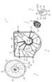
- FIG. 1A and 1B are external perspective views of a front side and a rear side of a fan device.
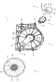
- FIG. 2 is an exploded perspective view of the fan unit as viewed from the front side.
- FIG. 2 is an exploded perspective view of the fan device as viewed from the rear side.
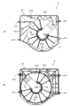
- FIG. 1A is a front view and FIG. 1B is a rear view of the shroud.
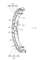
- 6 is a cross-sectional view of the motor support portion taken along line VI-VI in FIG. 5(A).
- 2A is a perspective view of the front side and the back side of the heat shield plate;
- FIG. 4 is a cross-sectional view of a main portion of a motor support portion and a heat shield plate.
- a fan device which is mounted on a vehicle such as an automobile and cools the engine coolant flowing through a radiator (object to be cooled).
- FIG. 1 is an external perspective view of the front side (A) and rear side (B) of the fan unit 1.
- Figure 2 is an exploded perspective view of the fan unit 1 as viewed from the front side.
- Figure 3 is an exploded perspective view of the fan unit 1 as viewed from the rear side.
- the fan unit 1 mainly comprises a motor 2, a fan 3, a shroud 4, and a heat shield 5.
- the fan unit 1 is installed, for example, in the engine room so as to face the radiator in the fore-and-aft direction. More specifically, in the engine room of a typical automobile, the radiator, fan unit 1, and engine are arranged in this order from front to rear. In other words, the fan unit 1 is arranged between the radiator and the engine in the fore-and-aft direction.
- the front side (radiator side) of the fan unit 1 will be referred to as the "front side”
- the rear side (engine side) of the fan unit 1 will be referred to as the "rear side.”
- the shroud 4 is fixed in the engine compartment with bolts or the like.
- the shroud 4 supports the motor 2 and houses the fan 3 attached to the motor 2.
- the driving force of the motor 2 is transmitted to the fan 3, which rotates to generate cooling air that flows from the front side to the rear side of the fan unit 1.
- the heat shield 5 covers the motor 2 from the rear side, blocking the radiant heat emitted from the engine and preventing it from reaching the motor 2.
- Fig. 4 is a vertical cross-sectional view of the motor 2.
- the motor 2 according to this embodiment is an outer rotor side brushless motor.
- the motor 2 is a so-called "mechanically and electrically integrated" electric motor in which a driver circuit 25 that controls the brushless motor is integrated.
- the motor 2 mainly includes a motor bracket 21, a shaft 22, a rotor 23, a stator 24, a driver circuit 25, a driver case 26, and a connector unit 27 (see Figs. 2 and 3).
- the motor bracket 21 has a generally plate-like outer shape.
- the motor bracket 21 supports the components of the motor 2 (i.e., the shaft 22, rotor 23, stator 24, driver circuit 25, driver case 26, and connector unit 27) on the front or back side.
- the axial direction of the shaft 22 will be referred to simply as the "axial direction”
- the radial direction centered on the axis of the shaft 22 will be referred to simply as the “radial direction”
- the circumferential direction centered on the axis of the shaft 22 will be referred to simply as the "circumferential direction”.
- the rotor 23 is rotatably supported on the shaft 22 via bearings 22A and 22B on the surface side of the motor bracket 21.
- the rotor 23 has a number of permanent magnets 231 arranged at equal intervals in the circumferential direction so as to surround the outer periphery of the stator 24, and a rotor yoke 232 that covers the stator 24 and the number of permanent magnets 231.
- the rotor yoke 232 is arranged on the surface side of the motor bracket 21 so as to be concentric with the axis of the shaft 22.
- the rotor yoke 232 has an outer peripheral wall 232A, an inner peripheral wall 232B, and a connecting wall 232C.
- the outer peripheral wall 232A has a cylindrical outer shape.
- the outer peripheral wall 232A is disposed radially outward from the stator 24.
- the inner peripheral surface of the outer peripheral wall 232A supports a plurality of permanent magnets 231.
- the plurality of permanent magnets 231 are fixed to the inner peripheral surface of the outer peripheral wall 232A at a predetermined interval in the circumferential direction.
- the inner peripheral wall 232B has a cylindrical outer shape.
- the inner peripheral wall 232B is disposed radially inward from the stator 24.
- the inner peripheral wall 232B is rotatably supported on the shaft 22 via the bearings 22A and 22B.
- the connecting wall 232C has a disk-shaped outer shape.
- the connecting wall 232C connects the axial ends of the outer peripheral wall 232A and the inner peripheral wall 232B. More specifically, the connecting wall 232C connects the outer peripheral wall 232A and the inner peripheral wall 232B on the other axial end side of the shaft 22 (i.e., the side opposite the motor bracket 21).
- the stator 24 is housed in a space surrounded by the outer peripheral wall 232A, the inner peripheral wall 232B, the connecting wall 232C, and the motor bracket 21.
- the stator 24 is fixed to the surface side of the motor bracket 21, radially inward from the multiple permanent magnets 231.
- the stator 24 faces the multiple permanent magnets 231 with a predetermined gap in the radial direction.
- the stator 24 has a cylindrical stator core 241, a number of teeth 242 protruding radially outward from the stator core 241, and a conductive coil 243 wound around the teeth 242 covered with an insulating insulator.
- the stator 24 generates a magnetic field when a current flows through the coil 243.
- the rotor yoke 232 rotates around the axis of the shaft 22 due to the attractive and repulsive forces generated between the magnetic field generated by the coil 243 and the multiple permanent magnets 231.
- the driver circuit 25 controls the generation of a magnetic field by the coil 243 by switching the timing of supplying current to the coil 243.
- the driver circuit 25 is composed of a circuit board and electronic components mounted on the circuit board.
- the driver case 26 is fixed to the rear side of the motor bracket 21 (i.e., the side opposite the shaft 22, rotor 23, and stator 24).
- An accommodation space 28 is formed between the rear side of the motor bracket 21 and the driver case 26.
- the driver circuit 25 is housed in the accommodation space 28 formed on the rear side of the motor bracket 21.
- the connector unit 27 is attached to the end of the motor bracket 21.
- the connector unit 27 is an integrated unit of two connectors to which an external harness is connected.
- the driver circuit 25 is electrically connected to an external device (e.g., an automobile control device) via the connector unit 27.
- the fan 3 has a boss 31 fixed to the rotor yoke 232, a plurality of blades 32 (nine in this embodiment) each protruding radially outward from circumferentially spaced positions on the outer circumferential surface of the boss 31, and a plurality of connecting members 33 (nine in this embodiment) connecting adjacent blades 32 at their tips.
- the fan 3 rotates integrally with the rotor 23, with the axis of the shaft 22 as the center of rotation.
- the boss 31 also includes a disk-shaped disk portion 311 and a cylindrical peripheral wall portion 312 that protrudes from the outer edge of the disk portion 311 toward the motor 2 and has a plurality of blades 32 attached to it.
- the disk portion 311 faces the connecting wall 232C of the rotor yoke 232
- the peripheral wall portion 312 surrounds the outer peripheral wall 232A of the rotor yoke 232.
- the inner diameter dimension of the peripheral wall portion 312 of the boss 31 is set slightly larger than the outer dimension of the rotor yoke 232.
- Fig. 5 is a front view (A) and a rear view (B) of the shroud 4.
- Fig. 6 is a cross-sectional view of the motor support part 42 taken along line VI-VI in Fig. 5(A).
- the shroud 4 is made up of a shroud main body 41, the motor support part 42, and a plurality of stays 43 (11 in this embodiment).
- the shroud 4 is integrally molded, for example, by injection molding a resin material.
- the shroud body 41 has a generally plate-like outer shape.
- the outer peripheral surface of the shroud body 41 is provided with a number of fixed portions 411 for fixing the shroud 4 (in other words, the fan unit 1) in the engine room with bolts or the like.
- the shroud body 41 also has a fan accommodating hole 412 that penetrates in the thickness direction.
- the fan accommodating hole 412 is a circular through-hole for accommodating the fan 3.
- the diameter of the fan accommodating hole 412 is set slightly larger than the outer dimensions of the fan 3 (i.e., the diameter of an imaginary circle connecting the tips of the multiple blades 32).
- a plurality of reinforcing ribs 413 are formed on the front and rear surfaces of the shroud body 41.
- the reinforcing ribs 413 protrude in the thickness direction from the front and rear surfaces of the shroud body 41 and extend in any direction.
- the reinforcing ribs 413 on the front surface side of the shroud body 41 may be inclined radially outward in the opposite direction (counterclockwise) to the rotation direction (clockwise) of the fan 3 with respect to an imaginary line (dash line) that extends radially through the center of the fan accommodating hole 412. This allows the air on the front surface side of the shroud body 41 to flow smoothly into the fan accommodating hole 412, thereby increasing the amount of cooling air passing through the fan device 1.
- the motor support part 42 is disposed inside the fan accommodating hole 412 (more specifically, in the center of the fan accommodating hole 412) to support the motor 2.
- the motor support part 42 has a generally arc-shaped outer shape. As shown in Figures 5 and 6, the motor support part 42 mainly includes an inner circumferential wall 421, an outer circumferential wall 422, a plurality of connecting walls 423, a motor fixing part 424, and a heat shield fixing part 425.
- the inner peripheral wall 421 and the outer peripheral wall 422 have a generally arc-shaped outer shape.
- the outer peripheral wall 422 is disposed radially outward from the inner peripheral wall 421. That is, the inner peripheral wall 421 and the outer peripheral wall 422 are disposed at a predetermined distance in the radial direction.
- the inner diameter dimension of the inner peripheral wall 421 is set to be slightly larger than the outer dimension of the rotor yoke 232.
- the outer dimensions of the inner peripheral walls 421 and 422 are set to be slightly larger than the outer dimensions of the boss 31 (more specifically, the peripheral wall portion 312).
- the connecting walls 423 connect the outer peripheral surface of the inner peripheral wall 421 and the inner peripheral surface of the outer peripheral wall 422 at positions spaced apart in the circumferential direction.
- the space surrounded by the outer peripheral surface of the inner peripheral wall 421, the inner peripheral surface of the outer peripheral wall 422, and the adjacent connecting walls 423 functions as an air guide passage 426 that penetrates the motor support part 42 in the thickness direction.
- the motor support part 42 has multiple air guide passages 426 formed at positions spaced apart in the circumferential direction, each of which penetrates in the thickness direction.
- the multiple air guide passages 426 are located radially outward from the boss 31.
- the multiple air guide passages 426 face the multiple blades 32.
- the cooling air generated by the fan 3 passes through the air guide passages 426 from the front side to the back side of the motor support part 42.
- the outer peripheral surface of the inner peripheral wall 421 that defines the air guide passage 426 extends generally in the thickness direction of the motor support portion 42 (in other words, the shroud 4).
- the inner peripheral surface of the outer peripheral wall 422 that defines the air guide passage 426 is inclined radially inward from the front surface side to the rear surface side of the motor support portion 42. That is, the air guide passage 426 is inclined radially inward from the front surface side to the rear surface side of the motor support portion 42.
- the opening area of the air guide passage 426 on the rear surface side of the motor support portion 42 is set smaller than the opening area of the air guide passage 426 on the front surface side of the motor support portion 42. That is, the opening area of the air guide passage 426 gradually decreases from the front surface side to the rear surface side of the motor support portion 42.
- the inner circumferential surface of the outer peripheral wall 422 that defines the air guide passage 426 is composed of a first surface 422A on the front surface side of the motor support portion 42, a second surface 422B on the rear surface side of the motor support portion 42, and a step 422C between the first surface 422A and the second surface 422B.
- the first surface 422A and the second surface 422B are both inclined radially inward from the front surface side to the rear surface side of the motor support portion 42.
- the inclination angle of the second surface 422B is set to be larger than the inclination angle of the first surface 422A.
- the opening area of the air guide passage 426 decreases gradually from the front surface side to the rear surface side of the motor support portion 42 in the region of the first surface 422A and decreases rapidly in the region of the second surface 422B.
- the motor fixing portion 424 is a portion through which a bolt for fixing the motor 2 to the motor support portion 42 is inserted. More specifically, the front side of the motor 2 is abutted against the rear side of the motor support portion 42. This allows the bolt holes in the motor bracket 21 to communicate with the bolt holes in the motor fixing portion 424.
- the motor 2 is supported on the rear side of the motor support portion 42 by screwing a nut onto the tip of the bolt that has passed through the communicating bolt hole. At this time, the rotor yoke 232 passes inside the inner circumferential wall 421 and protrudes on the front side of the motor support portion 42.
- the boss 31 is placed on the rotor yoke 232 protruding on the front side of the motor support portion 42 and fixed with a bolt, thereby attaching the fan 3 to the motor 2.
- the fan 3 is disposed on the front side of the motor support portion 42.
- the heat shield fixing portion 425 is a portion through which a bolt is inserted to fix the heat shield 5 to the motor support portion 42.
- the heat shield 5 is positioned so as to cover the motor 2 attached to the motor support portion 42 from the rear side. This allows the bolt holes 55 (see FIG. 7) that penetrate the heat shield 5 in the thickness direction to communicate with the bolt holes provided in the heat shield fixing portion 425.
- the heat shield 5 covering the motor 2 from the rear side is fixed to the motor support portion 42 by screwing a nut onto the tip of the bolt that has passed through the communicating bolt hole.
- the multiple stays 43 extend radially from the motor support portion 42 toward the shroud body 41 at positions spaced apart in the circumferential direction. More specifically, the stays 43 connect the outer peripheral surface of the outer peripheral wall 422 to the surface that defines the fan accommodating hole 412 of the shroud body 41. As a result, the motor support portion 42 is supported by the shroud body 41 at the center of the fan accommodating hole 412.
- Fig. 7 is a perspective view of the front side (A) and the back side (B) of the heat shield 5.
- Fig. 8 is a cross-sectional view of the main parts of the motor support part 42 and the heat shield 5.
- the heat shield 5 is disposed between the motor 2 and the engine. This prevents infrared rays emitted from the engine from reaching the motor 2 (in other words, blocks the radiant heat of the engine).
- the heat shield 5 also discharges the cooling air guided to the back side of the motor 2 through the air guide passage 426 and an air guide section 52 described later.
- the heat shield 5 mainly comprises a heat shield main body 51 and a plurality of air guide sections 52.
- the heat shield body 51 has a generally flat plate-like outer shape.
- the heat shield body 51 has multiple exhaust holes 53 and multiple louvers 54 formed therein.
- the exhaust holes 53 are through holes that penetrate the heat shield body 51 in the thickness direction.
- the exhaust holes 53 are elongated holes formed in the shape of a slit.
- the exhaust holes 53 exhaust the cooling air that is guided between the driver case 26 and the heat shield body 51 by the air guide section 52.
- the louvers 54 are provided adjacent to the exhaust holes 53.
- the louvers 54 are provided at an incline with respect to the thickness direction of the heat shield body 51. More specifically, the louvers 54 are inclined toward the surface side (i.e., the motor 2 side) of the heat shield body 51.
- the louvers 54 control the exhaust direction of the cooling air through the exhaust holes 53. More specifically, the louvers 54 exhaust the cooling air guided between the driver case 26 and the heat shield body 51 from the exhaust holes 53 along the inclined surface of the louvers 54.
- the opening area A1 of the exhaust holes 53 as viewed from the thickness direction of the heat shield 5 is set smaller than the opening area A2 of the exhaust holes 53 as viewed obliquely along the inclination direction of the louvers 54.
- the multiple air guide sections 52 are provided on the outer edge of the heat shield body 51.
- the air guide sections 52 are inclined toward the front side of the heat shield body 51 (i.e., toward the motor support section 42). As shown in FIG. 8, when the heat shield 5 is attached to the heat shield fixing section 425, the air guide sections 52 are arranged facing the air guide passage 426 on the rear side of the motor support section 42.
- the air guide sections 52 are located radially inward from the outer peripheral wall 422.
- the air guide sections 52 guide the cooling air generated by the fan 3 and passing through the air guide passage 426 to the rear side of the motor bracket 21 (in other words, the space between the driver case 26 and the heat shield fixing section 425).
- the cooling air generated by the fan 3 inclines radially inward along the inner circumferential surface of the outer wall 422 as it passes through the air guide 426, and accelerates as the opening area decreases.
- the cooling air that has passed through the air guide 426 is guided by the air guide section 52 into the space between the driver case 26 and the heat shield fixing section 425.
- the air guided into the space between the driver case 26 and the heat shield fixing section 425 cools the driver case 26 (more specifically, the driver circuit 25), and is then exhausted from the air exhaust hole 53 along the louvers 54.
- the heat shield 5 is formed integrally from, for example, a steel plate. That is, bolt holes 55 are formed in predetermined positions of the steel plate by punching. Furthermore, slit-shaped openings are formed by punching in the part that will become the heat shield body 51, and the part adjacent to the opening is bent toward the front surface by bending to form the air exhaust holes 53 and louvers 54. Furthermore, the outer edge of the heat shield body 51 is bent toward the front surface to form the air guide section 52.
- the cooling air that has passed through the air guide passage 426 provided in the motor support section 42 is guided to the driver case 26 through the air guide section 52.
- This allows the motor 2 (more specifically, the driver circuit 25) to be properly cooled.
- the deterioration of the motor 2 over time can be delayed, which extends the life of the fan device 1 and contributes to reducing waste and defective products.
- an air guide passage 426 is provided in the existing motor support portion 42, and the air guide portion 52 is positioned so that it does not extend radially outward from the motor support portion 42. This makes it possible to minimize the amount of cooling air blocked by the air guide portion 52. As a result, it is possible to ensure the cooling air required to cool the radiator without increasing the size of the fan device 1.
- the cooling air that has passed through the air guide passage 426 can be efficiently guided to the motor 2 side. Furthermore, according to the above embodiment, by gradually reducing the opening area of the air guide passage 426 toward the outlet, the cooling air passing through the air guide passage 426 can be accelerated. As a result, the motor 2 can be efficiently cooled.
- the driver circuit 25 (more specifically, the driver case 26) with the heat shield 5
- the temperature of the motor 2 (more specifically, the driver circuit 25) from increasing due to radiant heat from the engine.
- This allows the driver circuit 25 to be efficiently cooled with a small amount of cooling air. As a result, it is possible to further prevent the fan device 1 from becoming larger.
- the driver circuit 25 can be cooled efficiently with even less cooling air.
- the exhaust direction of the cooling air can be controlled by providing louvers 54 adjacent to the exhaust holes 53. Furthermore, by making the opening area A1 of the exhaust holes 53 as viewed in the thickness direction of the heat shield 5 smaller than the opening area A2 of the exhaust holes 53 as viewed obliquely along the inclination direction of the louvers 54, the amount of infrared rays reaching the motor 2 from the engine through the exhaust holes 53 can be reduced without reducing the amount of cooling air exhausted.
- the fan device 1 is mounted on a vehicle driven by an engine
- the vehicle on which the fan device 1 is mounted may also be driven by an electric motor.
- the heat shield body 51 can be omitted (i.e., the air guide section 52 may exist alone).
- an example of a radiator has been described as an object to be cooled by the fan device 1, but the object to be cooled by the fan device 1 is not limited to this.
- Fan device 2 Motor 3 : Fan 4 : Shroud 5 : Heat shield 21 : Motor bracket 22 : Shaft 22A, 22B : Bearing 23 : Rotor 24 : Stator 25 : Driver circuit 26 : Driver case 27 : Connector unit 28 : Storage space 31 : Boss 32 : Blade 33 : Connection member 41 : Shroud body 42 : Motor support portion 43 : Stay 51 : Heat shield body 52 : Air guide portion 53 : Air exhaust hole 54 : Louver 55 : Bolt hole 231 : Permanent magnet 232 : Rotor yoke 232A, 422 : Outer peripheral wall 232B, 421 : Inner peripheral wall 232C : Connection wall 241 : Stator core 242 : Teeth 243 : Coil 311 : Disk portion 312 : Peripheral wall portion 411 : Fixed portion 412 : Fan accommodating hole 413 : Reinforcing rib 422A : First surface 422B : Second surface 422
Landscapes
- Engineering & Computer Science (AREA)
- Mechanical Engineering (AREA)
- General Engineering & Computer Science (AREA)
- Physics & Mathematics (AREA)
- Thermal Sciences (AREA)
- Chemical & Material Sciences (AREA)
- Combustion & Propulsion (AREA)
- Microelectronics & Electronic Packaging (AREA)
- Structures Of Non-Positive Displacement Pumps (AREA)
- Motor Or Generator Frames (AREA)
- Motor Or Generator Cooling System (AREA)
Abstract
Description
まず、図1及び図2を参照して、ファン装置1の全体構成を説明する。図1は、ファン装置1の表面側(A)及び背面側(B)の外観斜視図である。図2は、ファン装置1の表面側から見た分解斜視図である。図3は、ファン装置1の背面側から見た分解斜視図である。図1~図3に示すように、ファン装置1は、モータ2と、ファン3と、シュラウド4と、遮熱板5とを主に備える。
次に、図4を参照して、モータ2の構成を説明する。図4は、モータ2の縦断面図である。本実施形態に係るモータ2は、アウターロータ側のブラシレスモータである。また、モータ2は、ブラシレスモータを制御するドライバ回路25が一体化された、所謂「機電一体型」の電動モータである。図4に示すように、モータ2は、モータブラケット21と、シャフト22と、ロータ23と、ステータ24と、ドライバ回路25と、ドライバケース26と、コネクタユニット27(図2及び図3参照)とを主に備える。
図1~図3に示すように、ファン3は、ロータヨーク232に固定されるボス31と、ボス31の外周面の周方向に離間した位置から各々が径方向外向きに突出する複数(本実施形態では9枚)のブレード32と、隣り合うブレード32同士を先端側で連結する複数(本実施形態では9つ)の連結部材33とを有する。ファン3は、シャフト22の軸心上を回転中心として、ロータ23と一体回転する。
図5は、シュラウド4の表面図(A)及び背面図(B)である。図6は、図5(A)のVI-VIにおけるモータ支持部42の断面図である。図5及び図6に示すように、シュラウド4は、シュラウド本体41と、モータ支持部42と、複数のステー43(本実施形態では、11個)とで構成される。シュラウド4は、例えば、樹脂材料を射出成形して一体成形される。
図7は、遮熱板5の表面側(A)及び背面側(B)の斜視図である。図8は、モータ支持部42及び遮熱板5の要部断面図である。遮熱板5は、モータ2と、エンジンとの間に配置される。これにより、エンジンから放出される赤外線がモータ2に到達するのを防ぐ(換言すれば、エンジンの輻射熱を遮断する)。また、遮熱板5は、導風路426及び後述する導風部52を通じてモータ2の背面側に導かれた冷却風を排出する。図7に示すように、遮熱板5は、遮熱板本体51と、複数の導風部52とを主に備える。
2 :モータ
3 :ファン
4 :シュラウド
5 :遮熱板
21 :モータブラケット
22 :シャフト
22A,22B :ベアリング
23 :ロータ
24 :ステータ
25 :ドライバ回路
26 :ドライバケース
27 :コネクタユニット
28 :収容空間
31 :ボス
32 :ブレード
33 :連結部材
41 :シュラウド本体
42 :モータ支持部
43 :ステー
51 :遮熱板本体
52 :導風部
53 :排風孔
54 :ルーバ
55 :ボルト穴
231 :永久磁石
232 :ロータヨーク
232A,422 :外周壁
232B,421 :内周壁
232C :連結壁
241 :ステータコア
242 :ティース
243 :コイル
311 :円盤部
312 :周壁部
411 :被固定部
412 :ファン収容孔
413 :補強リブ
422A :第1面
422B :第2面
422C :段差
423 :接続壁
424 :モータ固定部
425 :遮熱板固定部
426 :導風路
Claims (6)
- モータブラケット、前記モータブラケットの表面側に回転自在に支持されたロータ、前記モータブラケットの表面側に固定されて、前記ロータを回転させるための磁界を発生するコイルが巻装されたステータ、及び前記モータブラケットの背面側に固定されて、前記コイルによる磁界の発生を制御するドライバ回路を備えるモータと、
前記ロータに固定されたボス、及び前記ボスの外周面の周方向に離間した位置から各々が径方向外向きに突出するブレードを備えるファンと、
前記ファンを収容するファン収容孔が形成されたシュラウド本体、前記ファン収容孔の中央で前記モータを支持するモータ支持部、及び前記モータ支持部から前記シュラウド本体に向けて放射状に延びる複数のステーを備えるシュラウドとを備えるファン装置において、
前記ファンは、前記モータ支持部の表面側に配置され、
前記モータは、前記モータ支持部の背面側に支持され、
前記モータ支持部には、前記ボスより径方向外側の周方向に離間した位置において、各々が厚み方向に貫通する複数の導風路が形成され、
前記モータ支持部の背面側で前記導風路に対面して配置され、前記ファンによって生起され且つ前記導風路を通過した冷却風を、前記モータブラケットの背面側に導く導風部をさらに備えることを特徴とするファン装置。 - 請求項1に記載のファン装置において、
前記導風路は、前記モータ支持部の表面側から背面側に向かって、前記モータ支持部の径方向内側に傾斜していることを特徴とするファン装置。 - 請求項2に記載のファン装置において、
前記モータ支持部の背面側における前記導風路の開口面積は、前記モータ支持部の表面側における前記導風路の開口面積より小さいことを特徴とするファン装置。 - 請求項1に記載のファン装置において、
前記モータの背面側において、前記ドライバ回路を覆う遮熱板をさらに備え、
前記導風部は、前記遮熱板の外縁部に設けられていることを特徴とするファン装置。 - 請求項4に記載のファン装置において、
前記遮熱板には、厚み方向に貫通して、前記導風部によって前記ドライバ回路及び前記遮熱板の間に導かれた冷却風を排出する排風孔が形成されていることを特徴とするファン装置。 - 請求項5に記載のファン装置において、
前記遮熱板は、前記排風孔から排出される冷却風の流れを制御するために、前記遮熱板の厚み方向に対して傾斜したルーバを備え、
前記遮熱板の厚み方向から見た前記排風孔の開口面積は、前記ルーバの傾斜方向に沿って斜めから見た前記排風孔の開口面積より小さいことを特徴とするファン装置。
Priority Applications (2)
| Application Number | Priority Date | Filing Date | Title |
|---|---|---|---|
| US18/558,369 US12416309B2 (en) | 2022-11-16 | 2023-05-16 | Fan device |
| CN202380011574.6A CN118355179A (zh) | 2022-11-16 | 2023-05-16 | 风机装置 |
Applications Claiming Priority (2)
| Application Number | Priority Date | Filing Date | Title |
|---|---|---|---|
| JP2022-183599 | 2022-11-16 | ||
| JP2022183599A JP7757266B2 (ja) | 2022-11-16 | 2022-11-16 | ファン装置 |
Publications (1)
| Publication Number | Publication Date |
|---|---|
| WO2024105902A1 true WO2024105902A1 (ja) | 2024-05-23 |
Family
ID=91084089
Family Applications (1)
| Application Number | Title | Priority Date | Filing Date |
|---|---|---|---|
| PCT/JP2023/018230 Ceased WO2024105902A1 (ja) | 2022-11-16 | 2023-05-16 | ファン装置 |
Country Status (4)
| Country | Link |
|---|---|
| US (1) | US12416309B2 (ja) |
| JP (1) | JP7757266B2 (ja) |
| CN (1) | CN118355179A (ja) |
| WO (1) | WO2024105902A1 (ja) |
Citations (6)
| Publication number | Priority date | Publication date | Assignee | Title |
|---|---|---|---|---|
| JPH021498U (ja) * | 1988-06-15 | 1990-01-08 | ||
| JPH0377025U (ja) * | 1989-11-27 | 1991-08-01 | ||
| KR20030052300A (ko) * | 2001-12-20 | 2003-06-27 | 한라공조주식회사 | 차량용 쿨링팬 모터의 냉각구조 |
| JP2009074462A (ja) * | 2007-09-21 | 2009-04-09 | Mitsubishi Heavy Ind Ltd | ファンモータ |
| JP2015158203A (ja) * | 2014-02-24 | 2015-09-03 | ジョンソン エレクトリック ソシエテ アノニム | ファンアセンブリ |
| JP2019052576A (ja) * | 2017-09-14 | 2019-04-04 | 株式会社ミツバ | 送風装置 |
Family Cites Families (6)
| Publication number | Priority date | Publication date | Assignee | Title |
|---|---|---|---|---|
| JPH064669B2 (ja) | 1988-03-09 | 1994-01-19 | 工業技術院長 | ポリエン物質及び肥満細飽機能調節剤 |
| JPH0377025A (ja) | 1989-08-21 | 1991-04-02 | Fuji Electric Co Ltd | タービン発電機の振動監視装置 |
| US6227822B1 (en) * | 1998-10-20 | 2001-05-08 | Lakewood Engineering And Manufacturing Co. | Fan with improved electric motor and mounting |
| JP6787860B2 (ja) * | 2017-09-14 | 2020-11-18 | 株式会社ミツバ | 送風装置 |
| US10660235B2 (en) * | 2018-10-17 | 2020-05-19 | Arris Enterprises Llc | Fan with pivotable blades, and corresponding electronics cooling system and methods |
| KR102710172B1 (ko) * | 2020-03-13 | 2024-09-25 | 엘지전자 주식회사 | 팬모듈 및 이를 구비하는 휴대형 공기정화기 |
-
2022
- 2022-11-16 JP JP2022183599A patent/JP7757266B2/ja active Active
-
2023
- 2023-05-16 WO PCT/JP2023/018230 patent/WO2024105902A1/ja not_active Ceased
- 2023-05-16 CN CN202380011574.6A patent/CN118355179A/zh active Pending
- 2023-05-16 US US18/558,369 patent/US12416309B2/en active Active
Patent Citations (6)
| Publication number | Priority date | Publication date | Assignee | Title |
|---|---|---|---|---|
| JPH021498U (ja) * | 1988-06-15 | 1990-01-08 | ||
| JPH0377025U (ja) * | 1989-11-27 | 1991-08-01 | ||
| KR20030052300A (ko) * | 2001-12-20 | 2003-06-27 | 한라공조주식회사 | 차량용 쿨링팬 모터의 냉각구조 |
| JP2009074462A (ja) * | 2007-09-21 | 2009-04-09 | Mitsubishi Heavy Ind Ltd | ファンモータ |
| JP2015158203A (ja) * | 2014-02-24 | 2015-09-03 | ジョンソン エレクトリック ソシエテ アノニム | ファンアセンブリ |
| JP2019052576A (ja) * | 2017-09-14 | 2019-04-04 | 株式会社ミツバ | 送風装置 |
Also Published As
| Publication number | Publication date |
|---|---|
| JP2024072641A (ja) | 2024-05-28 |
| US20250084857A1 (en) | 2025-03-13 |
| US12416309B2 (en) | 2025-09-16 |
| CN118355179A (zh) | 2024-07-16 |
| JP7757266B2 (ja) | 2025-10-21 |
Similar Documents
| Publication | Publication Date | Title |
|---|---|---|
| JP5286689B2 (ja) | 冷却ファンユニット | |
| US7541702B2 (en) | Brushless fan motor | |
| CN101025168B (zh) | 风扇组件 | |
| US7946804B2 (en) | Axial fan unit having reduced noise generation | |
| CN101842600B (zh) | 轴流风扇及其制造方法 | |
| JP6707954B2 (ja) | ファンモータ | |
| US20070098571A1 (en) | Centrifugal fan | |
| JP5072506B2 (ja) | ファンモータ | |
| JP2008541686A (ja) | 電動機 | |
| JP2008082328A (ja) | 遠心ファン | |
| JPWO2008065985A1 (ja) | 直列式軸流ファン | |
| CN109578300B (zh) | 离心风扇 | |
| CN106468283A (zh) | 离心风扇 | |
| CN112610512A (zh) | 风机的风罩、风机以及电器 | |
| US20070264123A1 (en) | Counter-rotating fan | |
| JP7757266B2 (ja) | ファン装置 | |
| US8801375B2 (en) | Fan arrangement | |
| CN119790232A (zh) | 用于相应车辆、特别是机动车辆的加热、通风和/或空调系统的马达支架和机动风扇单元 | |
| JP7792877B2 (ja) | ファン装置 | |
| KR100858290B1 (ko) | 공랭식 전동장치 | |
| CN223241667U (zh) | 风机组件 | |
| JP2021011867A (ja) | ファン装置 | |
| JP7722287B2 (ja) | 電気機器 | |
| JPH06335201A (ja) | アウタロータ電動機の回転子構造 | |
| JP2025181309A (ja) | ブラシレスモータ |
Legal Events
| Date | Code | Title | Description |
|---|---|---|---|
| WWE | Wipo information: entry into national phase |
Ref document number: 18558369 Country of ref document: US |
|
| WWE | Wipo information: entry into national phase |
Ref document number: 202380011574.6 Country of ref document: CN |
|
| 121 | Ep: the epo has been informed by wipo that ep was designated in this application |
Ref document number: 23891064 Country of ref document: EP Kind code of ref document: A1 |
|
| WWP | Wipo information: published in national office |
Ref document number: 18558369 Country of ref document: US |
|
| NENP | Non-entry into the national phase |
Ref country code: DE |
|
| WWG | Wipo information: grant in national office |
Ref document number: 18558369 Country of ref document: US |
|
| 122 | Ep: pct application non-entry in european phase |
Ref document number: 23891064 Country of ref document: EP Kind code of ref document: A1 |