WO2024116257A1 - チャック生爪、チャック生爪の成形方法、ワーク加工方法、および、ハイブリッド工作機械 - Google Patents
チャック生爪、チャック生爪の成形方法、ワーク加工方法、および、ハイブリッド工作機械 Download PDFInfo
- Publication number
- WO2024116257A1 WO2024116257A1 PCT/JP2022/043875 JP2022043875W WO2024116257A1 WO 2024116257 A1 WO2024116257 A1 WO 2024116257A1 JP 2022043875 W JP2022043875 W JP 2022043875W WO 2024116257 A1 WO2024116257 A1 WO 2024116257A1
- Authority
- WO
- WIPO (PCT)
- Prior art keywords
- workpiece
- chuck
- holding
- holding surface
- raw material
- Prior art date
- Legal status (The legal status is an assumption and is not a legal conclusion. Google has not performed a legal analysis and makes no representation as to the accuracy of the status listed.)
- Ceased
Links
Images









Classifications
-
- B—PERFORMING OPERATIONS; TRANSPORTING
- B23—MACHINE TOOLS; METAL-WORKING NOT OTHERWISE PROVIDED FOR
- B23B—TURNING; BORING
- B23B31/00—Chucks; Expansion mandrels; Adaptations thereof for remote control
- B23B31/02—Chucks
- B23B31/10—Chucks characterised by the retaining or gripping devices or their immediate operating means
- B23B31/12—Chucks with simultaneously-acting jaws, whether or not also individually adjustable
- B23B31/16—Chucks with simultaneously-acting jaws, whether or not also individually adjustable moving radially
- B23B31/1627—Details of the jaws
- B23B31/16275—Form of the jaws
-
- B—PERFORMING OPERATIONS; TRANSPORTING
- B23—MACHINE TOOLS; METAL-WORKING NOT OTHERWISE PROVIDED FOR
- B23B—TURNING; BORING
- B23B31/00—Chucks; Expansion mandrels; Adaptations thereof for remote control
- B23B31/02—Chucks
- B23B31/10—Chucks characterised by the retaining or gripping devices or their immediate operating means
- B23B31/12—Chucks with simultaneously-acting jaws, whether or not also individually adjustable
- B23B31/16—Chucks with simultaneously-acting jaws, whether or not also individually adjustable moving radially
- B23B31/1627—Details of the jaws
-
- B—PERFORMING OPERATIONS; TRANSPORTING
- B23—MACHINE TOOLS; METAL-WORKING NOT OTHERWISE PROVIDED FOR
- B23B—TURNING; BORING
- B23B1/00—Methods for turning or working essentially requiring the use of turning-machines; Use of auxiliary equipment in connection with such methods
-
- B—PERFORMING OPERATIONS; TRANSPORTING
- B23—MACHINE TOOLS; METAL-WORKING NOT OTHERWISE PROVIDED FOR
- B23B—TURNING; BORING
- B23B3/00—General-purpose turning-machines or devices, e.g. centre lathes with feed rod and lead screw; Sets of turning-machines
- B23B3/30—Turning-machines with two or more working-spindles, e.g. in fixed arrangement
-
- B—PERFORMING OPERATIONS; TRANSPORTING
- B23—MACHINE TOOLS; METAL-WORKING NOT OTHERWISE PROVIDED FOR
- B23P—METAL-WORKING NOT OTHERWISE PROVIDED FOR; COMBINED OPERATIONS; UNIVERSAL MACHINE TOOLS
- B23P15/00—Making specific metal objects by operations not covered by a single other subclass or a group in this subclass
-
- B—PERFORMING OPERATIONS; TRANSPORTING
- B23—MACHINE TOOLS; METAL-WORKING NOT OTHERWISE PROVIDED FOR
- B23P—METAL-WORKING NOT OTHERWISE PROVIDED FOR; COMBINED OPERATIONS; UNIVERSAL MACHINE TOOLS
- B23P23/00—Machines or arrangements of machines for performing specified combinations of different metal-working operations not covered by a single other subclass
- B23P23/04—Machines or arrangements of machines for performing specified combinations of different metal-working operations not covered by a single other subclass for both machining and other metal-working operations
-
- B—PERFORMING OPERATIONS; TRANSPORTING
- B23—MACHINE TOOLS; METAL-WORKING NOT OTHERWISE PROVIDED FOR
- B23Q—DETAILS, COMPONENTS, OR ACCESSORIES FOR MACHINE TOOLS, e.g. ARRANGEMENTS FOR COPYING OR CONTROLLING; MACHINE TOOLS IN GENERAL CHARACTERISED BY THE CONSTRUCTION OF PARTICULAR DETAILS OR COMPONENTS; COMBINATIONS OR ASSOCIATIONS OF METAL-WORKING MACHINES, NOT DIRECTED TO A PARTICULAR RESULT
- B23Q2230/00—Special operations in a machine tool
- B23Q2230/006—Machining both ends of a workpiece consecutively
Definitions
- the present invention relates to a chuck jaw, a method for forming the chuck jaw, a method for machining a workpiece, and a hybrid machine tool.
- Patent Document 1 discloses a scroll chuck that can be used with both hard and soft jaws.
- the scroll chuck described in Patent Document 1 one of a trapezoidal V-groove and a trapezoidal protrusion is formed in the hard jaw, and the other of a trapezoidal V-groove and a trapezoidal protrusion is formed in the soft jaw.
- the hard jaw is attached to the master jaw, and the soft jaw is attached to the hard jaw via the trapezoidal V-groove and the trapezoidal protrusion.
- the object of the present invention is to provide a chuck jaw, a method for forming the chuck jaw, a workpiece processing method, and a hybrid machine tool that enable shortening of processing time.
- the chuck jaws are supported by the chuck body so as to be movable in a first direction away from the central axis of the chuck body and in a second direction toward the central axis.
- the chuck jaws have a first holding surface capable of holding a first surface of a workpiece, and a second holding surface capable of holding a machined surface of the workpiece.
- the hardness of the first holding surface is greater than the hardness of the second holding surface.
- the method for forming the chuck raw jaws includes a step of attaching a raw material block to the chuck body, and a step of forming the chuck raw jaws from the raw material block while the raw material block is attached to the chuck body.
- the step of forming the chuck raw jaws from the raw material block includes forming the first holding surface on the raw material block by processing the raw material block, and forming the second holding surface on the raw material block by cutting the raw material block.
- the workpiece machining method includes the steps of preparing a chuck jaw having a second holding surface and a first holding surface having a hardness higher than that of the second holding surface, attaching a workpiece to the chuck jaw supported by the chuck body so as to be movable in a first direction away from the central axis of a chuck body of a first workpiece holding device and in a second direction toward the central axis, cutting a first portion of the workpiece while the oxidized surface of the workpiece is held by the first holding surface of the chuck jaw, and machining a second portion of the workpiece while a machined surface formed by cutting the oxidized surface of the workpiece is held by the second holding surface of the chuck jaw.
- the hybrid machine tool includes a plurality of processing devices that form chuck jaws having a first holding surface that holds the oxidized surface of a workpiece and a second holding surface that holds the machined surface of the workpiece from a raw material block attached to a chuck body, a first workpiece holding device that holds the workpiece via the chuck jaws, and a control device that controls the plurality of processing devices and the first workpiece holding device.
- the first workpiece holding device includes the chuck body that supports the chuck jaws having the first holding surface and the second holding surface, a first drive device that moves the chuck jaws in a first direction away from the central axis of the chuck body or in a second direction toward the central axis, and a rotation drive device that rotates the chuck body around the central axis.
- the multiple processing devices include a first processing device that cuts the raw material block attached to the chuck body to form the second holding surface on the raw material block, and a second processing device that processes the raw material block attached to the chuck body to form the first holding surface on the raw material block, which has a hardness higher than that of the second holding surface.
- the present invention provides a chuck jaw that enables shortening of machining time, a method for forming the chuck jaw, a workpiece machining method, and a hybrid machine tool.
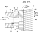
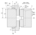
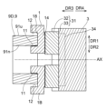
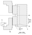
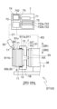
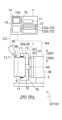
- FIG. 1 is a schematic cross-sectional view showing a state in which chuck jaws in a first embodiment are supported by a chuck body.
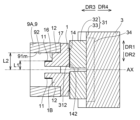
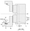
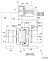
- FIG. 2 is a schematic cross-sectional view showing a state in which the chuck jaws in the first embodiment are supported by the chuck body.
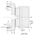
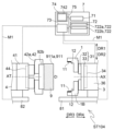
- FIG. 3 is a schematic cross-sectional view showing a state in which the chuck jaws in the first embodiment are supported by the chuck body.
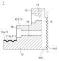
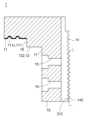
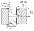
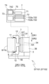
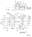
- FIG. 4 is a schematic cross-sectional view showing the chuck jaws in the first embodiment.
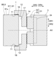
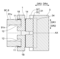
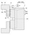
- FIG. 5 is a schematic cross-sectional view showing a state in which a chuck jaw in a first modified example of the first embodiment is supported by a chuck body.
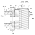
- FIG. 6 is a schematic cross-sectional view showing a state in which a chuck jaw in a first modified example of the first embodiment is supported by a chuck body.
- FIG. 7 is a schematic cross-sectional view showing a chuck jaw according to a first modified example of the first embodiment.
- FIG. 8 is a schematic perspective view showing a chuck soft jaw in a first modified example of the first embodiment.
- FIG. 9 is a schematic cross-sectional view showing a state in which a chuck soft jaw in a second modified example of the first embodiment is supported by a chuck body.
- FIG. 10 is a schematic cross-sectional view showing a state in which a chuck jaw in a second modified example of the first embodiment is supported by a chuck body.
- FIG. 11 is a schematic cross-sectional view showing a state in which a chuck soft jaw in a third modified example of the first embodiment is supported by a chuck body.
- FIG. 12 is a schematic cross-sectional view illustrating a state in which a chuck soft jaw in a fourth modified example of the first embodiment is supported by a chuck body.
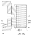
- FIG. 13 is a schematic cross-sectional view showing the state after the mounting step has been performed.
- FIG. 14 is a schematic cross-sectional view showing a state in which the raw material block is cut by the cutting tool.
- FIG. 15 is a schematic cross-sectional view showing a state in which a first holding surface is formed on the raw material block.
- FIG. 16 is a schematic cross-sectional view showing a state in which a second holding surface is formed on the raw material block.
- FIG. 17 is a schematic cross-sectional view showing a state in which a raw material block is cut by a cutting tool in a modified example of the method for forming chuck soft jaws.
- FIG. 18 is a schematic cross-sectional view showing a state in which a first holding surface is formed on a raw material block in a modified example of the method for forming a chuck soft jaw.
- FIG. 19 is a schematic cross-sectional view showing how projections and recesses are formed on the first holding surface.
- FIG. 20 is a schematic cross-sectional view showing a state in which a second holding surface is formed on a raw material block in a modified example of the method for forming a chuck soft jaw.
- FIG. 21 is a flowchart showing an example of a method for forming the chuck soft jaws in the first embodiment.
- FIG. 22 is a schematic diagram showing a state after the workpiece is attached to the chuck jaws.
- FIG. 23 is a diagram showing a schematic view of a state in which a first portion of a workpiece is cut while the workpiece is held by the first holding surfaces of the chuck soft jaws.
- FIG. 24 is a diagram showing a schematic view of a state in which a work is transferred from the first work holding device to the second work holding device.
- FIG. 25 is a diagram showing a schematic view of a state in which a workpiece is transferred from the first work holding device to the second work holding device.
- FIG. 26 is a diagram showing a schematic view of the oxidized surface of the workpiece being cut while the workpiece is held by the second workpiece holding device.
- FIG. 27 is a diagram showing a schematic view of a state in which a work is transferred from the second work holding device to the first work holding device.
- FIG. 28 is a diagram showing a schematic view of a state in which a second portion of the workpiece is machined while the workpiece is held by the second holding surfaces of the chuck soft jaws.
- FIG. 29 is a flowchart showing an example of a workpiece machining method in the first embodiment.
- FIG. 29 is a flowchart showing an example of a workpiece machining method in the first embodiment.
- FIG. 30 is a diagram showing a schematic view of how a workpiece is machined in a first modified example of the workpiece machining method.
- FIG. 31 is a diagram showing a schematic view of a workpiece being ground by a grinding tool.
- FIG. 32 is a diagram showing a schematic view of how a workpiece is machined in the second modified example of the workpiece machining method.
- FIG. 33 is a diagram showing a schematic view of how a workpiece is machined in the third modified example of the workpiece machining method.
- FIG. 34 is a diagram showing a schematic view of how a workpiece is machined in the fourth modified example of the workpiece machining method.
- FIG. 35 is a flowchart showing another example of the workpiece machining method in the first embodiment.
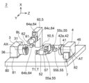
- FIG. 36 is a schematic perspective view illustrating the hybrid machine tool in the first embodiment.
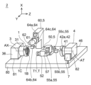
- FIG. 37 is a schematic perspective view illustrating the hybrid machine tool in the first embodiment.
- FIG. 38 is a schematic perspective view illustrating a hybrid machine tool in a first modified example of the first embodiment.
- FIG. 39 is a schematic perspective view illustrating a hybrid machine tool in a first modified example of the first embodiment.
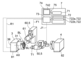
- FIG. 40 is a diagram showing a schematic diagram of a state in which a control device can transmit control commands to a plurality of control target devices.
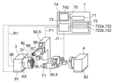
- FIG. 41 is a diagram showing a schematic diagram of a state in which a control device can transmit control commands to a plurality of control target devices.
- FIG. 42 is a diagram showing a schematic diagram of a state in which a control device can transmit control commands to a plurality of control target devices.
- first direction DR1 the direction away from the first axis AX, which is the central axis of the chuck body 31 of the first work holding device 3
- second direction DR2 the direction approaching the first axis AX, which is the central axis of the chuck body 31 of the first work holding device 3
- the direction along the central axis of the chuck body 31 of the first work holding device 3, which is the direction from the chuck body 31 toward the chuck soft jaws 1, is defined as the “third direction DR3.”
- the direction opposite to the third direction DR3 is defined as the “fourth direction DR4.”
- the central axis of the chuck body 31 of the first work holding device 3 is referred to as the "first axis AX.” Additionally, the central axis of the second chuck body 41 of the second work holding device 4 is referred to as the "second axis AT.”
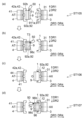
- Figs. 1 to 3 are schematic cross-sectional views showing the state in which the chuck raw jaw 1 in the first embodiment is supported by the chuck body 31.
- Fig. 2 shows the state in which the workpiece 9A is held by the first holding surface 11 of the chuck raw jaw 1
- Fig. 3 shows the state in which the workpiece 9A is held by the second holding surface 12 of the chuck raw jaw 1.
- Fig. 4 is a schematic cross-sectional view showing the chuck raw jaw 1 in the first embodiment. Figs.
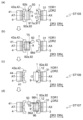
- FIG. 5 and 6 are schematic cross-sectional views showing the state in which the chuck raw jaw 1 in the first modified example of the first embodiment is supported by the chuck body 31.
- Fig. 5 shows the state in which the workpiece 9B is held by the first holding surface 11 of the chuck raw jaw 1
- Fig. 6 shows the state in which the workpiece 9B is held by the second holding surface 12 of the chuck raw jaw 1.
- Fig. 7 is a schematic cross-sectional view showing the chuck raw jaw 1 in the first modified example of the first embodiment.
- FIG. 8 is a schematic perspective view showing the chuck raw jaws 1 in the first modified example of the first embodiment.
- FIG. 10 are schematic cross-sectional views showing the state in which the chuck raw jaws 1 in the second modified example of the first embodiment are supported by the chuck body 31.
- FIG. 9 shows the state in which the workpiece 9C is held by the first holding surface 11 of the chuck raw jaws 1
- FIG. 10 shows the state in which the workpiece 9C is held by the second holding surface 12 of the chuck raw jaws 1.
- FIG. 11 is a schematic cross-sectional view showing the state in which the chuck raw jaws 1 in the third modified example of the first embodiment are supported by the chuck body 31.
- FIG. 12 is a schematic cross-sectional view showing the state in which the chuck raw jaws 1 in the fourth modified example of the first embodiment are supported by the chuck body 31.
- the chuck jaws 1 in the first embodiment are members supported by the chuck body 31. More specifically, the chuck jaws 1 are supported by the chuck body 31 so as to be movable in a first direction DR1 away from the first axis AX, which is the central axis of the chuck body 31, and in a second direction DR2 toward the first axis AX.
- the first direction DR1 corresponds to a radial direction away from the central axis of the chuck body 31.
- the second direction DR2 is opposite to the first direction DR1.
- the chuck body 31 has a movable part 32 and a base part 33 that movably supports the movable part 32.
- the chuck jaws 1, together with the movable part 32 of the chuck body 31, are movable in a first direction DR1 away from the first axis AX, which is the central axis of the chuck body 31.
- the chuck jaws 1, together with the movable part 32 of the chuck body 31, are movable in a second direction DR2 toward the first axis AX, which is the central axis of the chuck body 31.
- the chuck jaws 1 have a first holding surface 11 capable of holding a first surface 91 of the workpiece 9A (e.g., an oxidized surface 911 of the workpiece 9A). Also, as illustrated in FIG. 3, the chuck jaws 1 have a second holding surface 12 capable of holding a machined surface 92 of the workpiece 9A. The hardness of the first holding surface 11 is greater than the hardness of the second holding surface 12.
- the material constituting the chuck jaws 1 may be steel or other materials.
- the first holding surface 11 may be formed of high-hardness steel (e.g., steel containing a martensite phase) that is harder than the steel that forms the second holding surface 12.
- the first holding surface 11 may be formed of a metal material other than steel (e.g., titanium) that is harder than the steel that forms the second holding surface 12.
- the chuck jaws 1 have a first holding surface 11 (more specifically, the first holding surface 11 has a relatively high hardness) that has a hardness suitable for holding the first surface 91 of the workpiece 9A, and a second holding surface 12 (more specifically, the second holding surface 12 has a relatively low hardness) that has a hardness suitable for holding the machined surface 92 of the workpiece 9A.
- the first holding surface 11 is, for example, a surface that holds the oxidized surface 911 of the workpiece 9A.
- the oxidized surface 911 of the workpiece 9A has fine irregularities.
- the oxidized surface 911 needs to be held with strong force by the first holding surface 11.
- the first holding surface 11 is a surface having a relatively high hardness, the first holding surface 11 that comes into contact with the oxidized surface 911 with strong force is prevented from being damaged by the oxidized surface 911. Therefore, the durability of the chuck soft jaws 1 is improved, and the life of the chuck soft jaws 1 can be extended.
- the first holding surface 11 may have irregularities 111. More specifically, the first holding surface 11 may have spike-like protrusions or grooves 111v. When the first holding surface 11 has irregularities 111, the gripping ability of the first holding surface 11 with respect to the oxidized surface 911 of the workpiece 9A is improved.
- the first holding surface 11 may be a smooth surface (in other words, a surface without irregularities).
- the first holding surface 11 is a surface formed by heat treatment. More specifically, the first holding surface 11 is a surface 11a formed by hardening.
- the hardening process is performed, for example, by irradiating a laser beam onto the surface of the material that constitutes the chuck jaws 1.
- the material that constitutes the chuck jaws 1 is, for example, steel.
- the first holding surface 11 may be a metal laminated surface 11b.
- the metal laminated surface 11b is formed by laminating a metal material N having a higher hardness than the material constituting the raw material block of the chuck raw jaw 1 onto the surface of the material constituting the raw material block.
- the second holding surface 12 is a surface that holds the machined surface 92 of the workpiece 9A.
- the machined surface 92 of the workpiece 9A is a relatively smooth surface compared to the oxidized surface 911 (see Fig. 2) of the workpiece 9A.
- the second holding surface 12 is a surface having a relatively low hardness, the machined surface 92 of the workpiece 9A is prevented from being scratched by the second holding surface 12.
- the second holding surface 12 is a machined surface 122 formed by cutting.
- the second holding surface 12 can be made a smooth surface.
- the machined surface 92 of the workpiece 9A held by the second holding surface 12 is more effectively prevented from being damaged by the second holding surface 12.
- the second holding surface 12 is a smooth surface (in other words, a surface that does not have grooves, protrusions, etc.).
- the first retaining surface 11 and the second retaining surface 12 are arranged on a single block component 10 that is integrally molded. Therefore, in the example shown in FIG. 4, there is no need to connect the component on which the first retaining surface 11 is arranged and the component on which the second retaining surface 12 is arranged via a fixing member such as a bolt.
- the chuck jaws 1 have a base 14 attached to the chuck body 31.
- the base 14 may have a first uneven portion 142 that engages with a second uneven portion 312 formed on the chuck body 31.
- the attachment position of the chuck jaws 1 relative to the movable portion 32 of the chuck body 31 can be adjusted by adjusting the relative position of the first uneven portion 142 with respect to the second uneven portion 312.
- the chuck jaws 1 are attached to the chuck body 31 via a fixing member such as a bolt.
- the chuck jaws 1 are formed with a through hole portion 15 that can receive a fixing member such as a bolt.
- the second holding surface 12 is disposed between the first holding surface 11 and the base portion 14 in the direction along the first axis AX.
- each of the first holding surface 11 and the second holding surface 12 is substantially parallel to the first axis AX.
- the first holding surface 11 may be an arc-shaped surface with the first axis AX as its center line.
- the second holding surface 12 may be an arc-shaped surface with the first axis AX as its center line.
- the chuck jaw 1 has a first step surface 16.
- the first step surface 16 is, for example, substantially perpendicular to the first axis AX.
- the first step surface 16 is disposed between the first holding surface 11 and the second holding surface 12 in the direction along the first axis AX.
- the inner edge of the first step surface 16 may be connected to the first holding surface 11.
- the outer edge of the first step surface 16 may be connected to the second holding surface 12.
- the chuck jaw 1 has a second step surface 17.
- the second step surface 17 is, for example, substantially perpendicular to the first axis AX.
- the second step surface 17 is disposed closer to the base 14 than the second holding surface 12 in the direction along the first axis AX.
- the second step surface 17 may function as a positioning surface that positions the base end surface of the workpiece 9A (in other words, the end surface on the fourth direction DR4 side).
- the first step surface 16 may function as a positioning surface that positions the base end surface of the workpiece 9A.
- the first holding surface 11 is a surface that holds the inner surface 91n of the workpiece 9A (more specifically, the inner peripheral surface of the workpiece 9A).
- the second holding surface 12 is a surface that holds the surface 91m that is formed by cutting the inner surface 91n of the workpiece 9A (more specifically, the surface that is formed by cutting the inner peripheral surface of the workpiece 9A).
- the distance L2 between the first axis AX and the second holding surface 12 is greater than the distance L1 between the first axis AX and the first holding surface 11.
- the second holding surface 12 is disposed between the first holding surface 11 and the base 14 in a direction along the first axis AX.
- each of the first holding surface 11 and the second holding surface 12 is substantially parallel to the first axis AX.
- the chuck jaw 1 has a first step surface 16.
- the first step surface 16 is, for example, substantially perpendicular to the first axis AX.
- the first step surface 16 is disposed between the first holding surface 11 and the second holding surface 12 in the direction along the first axis AX.
- the outer edge of the first step surface 16 may be connected to the first holding surface 11.
- the inner edge of the first step surface 16 may be connected to the second holding surface 12.
- the chuck jaw 1 has a second step surface 17.
- the second step surface 17 is, for example, substantially perpendicular to the first axis AX.
- the second step surface 17 is disposed closer to the base 14 than the second holding surface 12 in the direction along the first axis AX.
- the first step surface 16 may function as a positioning surface that positions the base end surface of the workpiece 9B (in other words, the end surface on the fourth direction DR4 side).
- the second step surface 17 may function as a positioning surface that positions the base end surface of the workpiece 9B.
- the first holding surface 11 is a surface that holds the outer surface 91u of the workpiece 9B (more specifically, the outer peripheral surface of the workpiece 9B).
- the second holding surface 12 is a surface that holds a surface 91v that is formed by cutting the outer surface 91u of the workpiece 9B (more specifically, a surface that is formed by cutting the outer peripheral surface of the workpiece 9B).
- the distance L4 between the first axis AX and the second holding surface 12 is smaller than the distance L3 between the first axis AX and the first holding surface 11.
- the first holding surface 11 may be a first arcuate surface 115.
- the center line of the first arcuate surface 115 is preferably coaxial with the first axis AX.
- the second holding surface 12 may be a second arcuate surface 125.
- the center line of the second arcuate surface 125 is preferably coaxial with the first axis AX.
- the second holding surface 12 is arranged to face the first holding surface 11.
- each of the first holding surface 11 and the second holding surface 12 is substantially parallel to the first axis AX.
- the chuck jaw 1 has a connecting surface 18 connecting the first holding surface 11 and the second holding surface 12.
- the connecting surface 18 is, for example, substantially perpendicular to the first axis AX.
- the outer edge of the connecting surface 18 may be connected to the first holding surface 11.
- the inner edge of the connecting surface 18 may be connected to the second holding surface 12.
- the inner edge of the connecting surface 18 may be connected to the first holding surface 11, and the outer edge of the connecting surface 18 may be connected to the second holding surface 12.
- the connecting surface 18 may function as a positioning surface that positions the base end surface of the workpiece 9C (in other words, the end surface on the fourth direction DR4 side). Also, as illustrated in FIG. 10, when the workpiece 9C is held by the second holding surface 12, the connecting surface 18 may function as a positioning surface that positions the base end surface of the workpiece 9C.
- the first holding surface 11 is a surface that holds the outer surface 91u of the workpiece 9C (more specifically, the outer peripheral surface of the workpiece 9C).
- the second holding surface 12 is a surface that holds the surface 91m that is formed by cutting the inner surface 91n of the workpiece 9C (more specifically, the surface that is formed by cutting the inner peripheral surface of the workpiece 9C).
- the first holding surface 11 may be a surface that holds the inner surface 91n of the workpiece 9D (more specifically, the inner peripheral surface of the workpiece 9D).
- the second holding surface 12 may be a surface that holds a surface that is formed by cutting the outer surface 91u of the workpiece 9D (more specifically, a surface that is formed by cutting the outer peripheral surface of the workpiece 9D).
- a fourth modified example of the chuck jaw 1 will be described with reference to FIG. 12.
- the number of the first holding surface 11 that the chuck jaw 1 has is one
- the number of the second holding surface 12 that the chuck jaw 1 has is one.
- the chuck jaw 1 may have a plurality of first holding surfaces 11.
- the chuck jaw 1 may have a plurality of second holding surfaces 12.
- the hardness of each of the plurality of first holding surfaces 11 is higher than the hardness of each of the plurality of second holding surfaces 12.
- the first holding surfaces 11 and the second holding surfaces 12 are alternately arranged in the direction along the first axis AX.
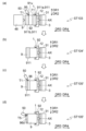
- Fig. 13 is a schematic cross-sectional view showing a state after the mounting process is performed.
- Fig. 14 is a schematic cross-sectional view showing a state in which the raw material block BL is cut by the cutting tool T1.
- Fig. 15 is a schematic cross-sectional view showing a state in which the first holding surface 11 is formed on the raw material block BL.
- Fig. 16 is a schematic cross-sectional view showing a state in which the second holding surface 12 is formed on the raw material block BL.
- Fig. 13 is a schematic cross-sectional view showing a state after the mounting process is performed.
- Fig. 14 is a schematic cross-sectional view showing a state in which the raw material block BL is cut by the cutting tool T1.
- Fig. 15 is a schematic cross-sectional view showing a state in which the first holding surface 11 is formed on the raw material block BL.
- Fig. 16 is a schematic cross-sectional view showing a state in which the second holding surface 12
- FIG. 17 is a schematic cross-sectional view showing a state in which the raw material block BL is cut by the cutting tool T1 in a modified example of the method for forming the chuck raw jaws.
- Fig. 18 is a schematic cross-sectional view showing a state in which the first holding surface 11 is formed on the raw material block BL in a modified example of the method for forming the chuck raw jaws.
- Fig. 19 is a schematic cross-sectional view showing a state in which the unevenness 111 is formed on the first holding surface 11.
- Fig. 20 is a schematic cross-sectional view showing a state in which the second holding surface 12 is formed on the raw material block BL in a modified example of the forming method of the chuck soft jaws.
- Fig. 21 is a flowchart showing an example of the forming method of the chuck soft jaws in the first embodiment.
- the chuck jaws formed by the chuck jaw forming method in the first embodiment may be the chuck jaws 1 illustrated in FIG. 4, the chuck jaws 1 illustrated in FIG. 7, the chuck jaws 1 illustrated in any of FIG. 10 to FIG. 12, or other chuck jaws.
- the raw material block BL that will be formed into the chuck jaws 1 is attached to the chuck body 31 (more specifically, the movable part 32 of the chuck body 31).
- the first process is the attachment process.
- the shape of the raw material block BL is preferably similar to the shape of the chuck raw jaw 1 after forming.
- the material constituting the raw material block BL may be steel or other materials.
- the raw material block BL is composed of one block part 10 that is integrally formed.
- the raw material block BL has a base 14 attached to the chuck body 31, an intermediate portion 10a supported by the base 14 and on which the second holding surface 12 is formed, and a tip portion 10b supported by the intermediate portion 10a and on which the first holding surface 11 is formed.
- the intermediate portion 10a is positioned closer to the third direction DR3 than the base 14, and the tip portion 10b is positioned closer to the third direction DR3 than the intermediate portion 10a.
- the mounting process may include mounting the raw material block BL to the movable part 32 of the chuck body 31 via a fixing member such as a bolt BT.
- the mounting process may also include engaging the first uneven part 142 of the raw material block BL with the second uneven part 312 of the chuck body 31.
- the chuck raw jaws 1 are formed from the raw material block BL.
- the second step ST2 is a forming process.
- the forming process is performed in a state where the raw material block BL is attached to the chuck body 31.
- the forming process includes multiple sub-steps.
- sub-step ST2-1 the raw material block BL attached to the chuck body 31 is cut by a cutting tool T1.
- Sub-step ST2-1 includes cutting the raw material block BL so as to form a cutting surface BL1 that corresponds to the shape and size of the workpiece 9 before machining.
- Sub-step ST2-1 may be performed in a state where the chuck body 31 to which the raw material block BL is attached is rotating around the first axis AX.
- Substep ST2-1 includes forming a cutting surface BL1 on the raw material block BL by cutting the raw material block BL with a cutting tool T1.
- the cutting surface BL1 may have irregularities (more specifically, grooves V).
- the cutting surface BL1 may be a smooth surface without irregularities.
- a first holding surface 11 is formed on the raw material block BL attached to the chuck body 31 by a second processing device 60 such as a laser irradiation device 61.
- Sub-step ST2-2 includes forming a first holding surface 11 on the raw material block BL having a hardness higher than the hardness of the original surface of the raw material block BL by processing the cutting surface BL1 of the raw material block BL.
- Sub-step ST2-2 also includes forming the first holding surface 11 corresponding to the shape and size of the workpiece 9 before machining.
- the first holding surface 11 is a surface capable of holding the oxidized surface 911 of the workpiece 9 (see FIG. 5, if necessary).
- sub-step ST2-2 the laser irradiation device 61 is used to form the first holding surface 11 on the raw material block BL attached to the chuck body 31. More specifically, sub-step ST2-2 includes the laser irradiation device 61 irradiating the cutting surface BL1 of the raw material block BL with laser light LB.
- the cutting surface BL1 is heat-treated (more specifically, hardened) by the laser light LB. As a result, the hardness of the cutting surface BL1 increases, and the cutting surface BL1 becomes the first holding surface 11 with high hardness.
- the cutting surface BL1 has unevenness
- the first holding surface 11 will also have unevenness.
- sub-step ST2-3 it is determined whether the formation accuracy of the first holding surface 11 satisfies the allowable accuracy. This determination may be made by visual inspection or by using any checking device.
- substep ST2-4 the first holding surface 11 is molded so that the forming accuracy of the first holding surface 11 satisfies the allowable accuracy. More specifically, the first holding surface 11 is machined using a cutting tool T1 or a grinding tool so that the forming accuracy of the first holding surface 11 satisfies the allowable accuracy. If it is determined that the forming accuracy of the first holding surface 11 satisfies the allowable accuracy (substep ST2-3: Yes), proceed to substep ST2-5. Note that substeps ST2-3 and ST2-4 may be omitted.
- Sub-step ST2-5 includes cutting the raw material block BL so that the second holding surface 12 is formed corresponding to the shape and size of the workpiece 9 after rough machining (more specifically, so that the second holding surface 12 is formed corresponding to the shape and size of the workpiece 9 after the oxidized surface 911 is removed).
- Sub-step ST2-5 includes forming the second holding surface 12 on the raw material block BL by cutting the raw material block BL.
- the second holding surface 12 is a smooth surface (in other words, a surface that does not have grooves, protrusions, etc.).
- Sub-step ST2-5 may be performed in a state where the chuck body 31 to which the raw material block BL is attached is rotating around the first axis AX.
- substep ST2-5 may be performed before substep ST2-1, after substep ST2-1, or in parallel with substep ST2-1. However, considering that the raw material block BL is thermally deformed by the execution of substep ST2-2, it is preferable that substep ST2-5 is performed after substep ST2-1 and substep ST2-2.
- a raw material block BL is attached to the chuck body 31 (more specifically, the movable part 32 of the chuck body 31).
- the first step ST1 is an attachment process.
- the attachment process has already been described, so a repeated description of the attachment process will be omitted.
- the chuck raw jaws 1 are formed from the raw material block BL.
- the second step ST2 is a forming process.
- the forming process is performed in a state in which the raw material block BL is attached to the chuck body 31.
- the forming process includes multiple sub-steps.
- sub-step ST2-1 the raw material block BL attached to the chuck body 31 is cut by a cutting tool T1.
- Sub-step ST2-1 includes cutting the raw material block BL so as to form a cutting surface BL1 that generally corresponds to the shape and size of the workpiece 9 before machining.
- Sub-step ST2-1 may be performed in a state where the chuck body 31 to which the raw material block BL is attached is rotating around the first axis AX.
- Substep ST2-1 includes forming a cutting surface BL1 on the raw material block BL by cutting the raw material block BL with a cutting tool T1.
- the cutting surface BL1 may be a smooth surface without any irregularities.
- the cutting surface BL1 may have irregularities (more specifically, grooves).
- a first holding surface 11 is formed on the raw material block BL attached to the chuck body 31 by a second processing device 60 such as an additional processing device 66.
- Substep ST2-2 includes forming a first holding surface 11 on the raw material block BL having a hardness higher than the hardness of the original surface of the raw material block BL by processing the cutting surface BL1 of the raw material block BL.
- Substep ST2-2 also includes forming the first holding surface 11 corresponding to the shape and size of the workpiece 9 before machining.
- the first holding surface 11 is a surface capable of holding the oxidized surface 911 of the workpiece 9 (see FIG. 5, if necessary).
- sub-step ST2-2 the additional processing device 66 is used to form the first holding surface 11 on the raw material block BL attached to the chuck body 31. More specifically, sub-step ST2-2 includes the additional processing device 66 adding a metal material N having a hardness higher than the hardness of the raw material block BL to the cutting surface BL1 of the raw material block BL.
- the additional processing device 66 supplies metal powder P toward the cutting surface BL1 and irradiates laser light LB toward the cutting surface BL1.
- the metal powder P heated by the energy of the laser light LB melts, and the molten metal adheres to the cutting surface BL1.
- the metal material N with high hardness adheres to the cutting surface BL1, and a first holding surface 11 with high hardness is formed so as to cover the cutting surface BL1.
- irregularities 111 may be formed on the first holding surface 11.
- the cutting tool T1 cuts the first holding surface 11, thereby forming irregularities 111 (more specifically, grooves 111v) on the first holding surface 11.
- sub-step ST2-3 it is determined whether the formation accuracy of the first holding surface 11 satisfies the allowable accuracy. This determination may be made by visual inspection or by using any checking device.
- substep ST2-4 the first holding surface 11 is molded so that the forming accuracy of the first holding surface 11 satisfies the allowable accuracy. More specifically, the first holding surface 11 is machined using a cutting tool T1 or a grinding tool so that the forming accuracy of the first holding surface 11 satisfies the allowable accuracy. If it is determined that the forming accuracy of the first holding surface 11 satisfies the allowable accuracy (substep ST2-3: Yes), proceed to substep ST2-5. Note that substeps ST2-3 and ST2-4 may be omitted.
- Sub-step ST2-5 includes cutting the raw material block BL so that the second holding surface 12 is formed corresponding to the shape and size of the workpiece 9 after rough machining (more specifically, so that the second holding surface 12 is formed corresponding to the shape and size of the workpiece 9 after the oxidized surface 911 is removed).
- Sub-step ST2-5 includes forming the second holding surface 12 on the raw material block BL by cutting the raw material block BL.
- the second holding surface 12 is a smooth surface (in other words, a surface that does not have grooves, protrusions, etc.).
- Sub-step ST2-5 may be performed in a state where the chuck body 31 to which the raw material block BL is attached is rotating around the first axis AX.
- substep ST2-5 may be performed before substep ST2-1, after substep ST2-1, or in parallel with substep ST2-1. However, considering that the raw material block BL is thermally deformed by the execution of substep ST2-2, it is preferable that substep ST2-5 is performed after substep ST2-1 and substep ST2-2.
- Fig. 22 is a diagram showing a state after the workpiece 9 is attached to the chuck soft jaws 1.
- Fig. 23 is a diagram showing a state in which the first portion 95 of the workpiece 9 is cut while the workpiece 9 is held by the first holding surface 11 of the chuck soft jaws 1.
- Figs. 24 and 25 are diagrams showing a state in which the workpiece 9 is transferred from the first workpiece holding device 3 to the second workpiece holding device 4.
- Fig. 26 is a diagram showing a state in which the oxidized surface 911 of the workpiece 9 is cut while the workpiece 9 is held by the second workpiece holding device 4.
- Fig. 22 is a diagram showing a state after the workpiece 9 is attached to the chuck soft jaws 1.
- Fig. 23 is a diagram showing a state in which the first portion 95 of the workpiece 9 is cut while the workpiece 9 is held by the first holding surface 11 of the chuck soft jaws 1.
- Figs. 24 and 25 are diagrams showing a state in which
- FIG. 27 is a diagram showing a state in which the workpiece 9 is transferred from the second workpiece holding device 4 to the first workpiece holding device 3.
- Fig. 28 is a diagram showing a state in which the second portion 96 of the workpiece 9 is machined while the workpiece 9 is held by the second holding surface 12 of the chuck soft jaws 1.
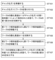
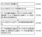
- Fig. 29 is a flowchart showing an example of a workpiece machining method in the first embodiment.
- Fig. 30 is a diagram showing a state in which the workpiece 9 is machined in a first modified example of the workpiece machining method.
- Fig. 31 is a diagram showing a state in which the workpiece 9 is ground by a grinding tool T2.
- FIG. 32 is a diagram showing a state in which the workpiece 9 is machined in a second modified example of the workpiece machining method.
- Fig. 33 is a diagram showing a state in which the workpiece 9 is machined in a third modified example of the workpiece machining method.
- Fig. 34 is a diagram showing a state in which the workpiece 9 is machined in a fourth modified example of the workpiece machining method.
- Fig. 35 is a flowchart showing another example of the workpiece machining method in the first embodiment.
- a chuck jaw 1 having a second holding surface 12 and a first holding surface 11 having a hardness higher than that of the second holding surface 12 is prepared.
- the first step ST1 is a preparation process.
- the chuck jaw 1 prepared in the preparation process may be any of the chuck jaws in the first embodiment described with reference to FIGS. 1 to 12, or may be another chuck jaw.
- the chuck jaw 1 prepared in the preparation process may be a chuck jaw formed by the chuck jaw forming method in the first embodiment, or may be another chuck jaw.
- the chuck jaws 1 are supported by the chuck body 31 so as to be movable in a first direction DR1 away from the first axis AX of the first work holding device 3, and in a second direction DR2 toward the first axis AX.
- the work 9 is attached to the chuck jaws 1 supported by the chuck body 31.
- the second step ST102 is a work attachment process.
- the first portion 95 of the workpiece 9 is cut.
- the third step ST103 is the first cutting process.
- the first portion 95 of the workpiece 9 is cut while the oxidized surface 911 of the workpiece 9 (more specifically, the oxidized surface 911a on the fourth direction DR4 side of the workpiece 9) is held by the first holding surface 11 of the chuck soft jaw 1.
- the first cutting process includes bringing the cutting tool T1 into contact with the first portion 95 of the workpiece 9 while the chuck body 31, which holds the workpiece 9 via the chuck jaws 1, is rotating about the first axis AX.
- the first portion 95 cut in the first cutting process includes the oxidized surface 911b of the workpiece 9 located on the third direction DR3 side of the first holding surface 11.
- the oxidized surface 911b on the third direction DR3 side of the workpiece 9 becomes the machined surface 92 (more specifically, the first machined surface 92b on the third direction DR3 side).
- the oxidized surface 911 has unevenness, slippage is likely to occur between the oxidized surface 911 and the first holding surface 11. Therefore, when performing the third step ST103, it is necessary to apply a relatively large gripping force from the first holding surface 11 to the workpiece 9. Since the first holding surface 11 has a relatively high hardness, the first holding surface 11 is suitable for applying a relatively large gripping force. In addition, since the first holding surface 11 has a relatively high hardness, the first holding surface 11 is not easily damaged due to contact between the first holding surface 11 and the oxidized surface 911.
- the first holding surface 11 may have unevenness 111 such as grooves (see Figures 4, 7, 16, and 20, if necessary). When the first holding surface 11 has unevenness 111, the gripping ability to the oxidized surface 911 of the workpiece 9 is improved.
- the fourth step ST104 is a first transfer process.
- the first transfer process may be performed automatically using the first work holding device 3 and the second work holding device 4.
- a part of the first transfer process may be performed using a transfer device other than the first work holding device 3 and the second work holding device 4 (more specifically, the transfer device is a gantry loader, a work exchange hand attached to the first head 52 described below, etc.), or may be performed manually.
- the first transfer process includes moving the chuck raw jaws 1 in a direction away from the oxidized surface 911a of the workpiece 9. This movement releases the workpiece 9 from the first holding surface 11 of the chuck raw jaws 1.
- the first transfer process also includes moving the jaws 42 of the second workpiece holding device 4 in a direction approaching the surface of the workpiece 9 (more specifically, the first machined surface 92b). This movement causes the surface of the workpiece 9 (more specifically, the first machined surface 92b) to be held by the jaws 42.
- the oxidized surface 911 of the workpiece 9 (more specifically, the oxidized surface 911a on the fourth direction DR4 side) is cut.
- the fifth step ST105 is a second cutting process.
- the second cutting process includes cutting the oxidized surface 911 of the workpiece 9 so that a machined surface 92 is formed on the workpiece 9 held by the second workpiece holding device 4. More specifically, the oxidized surface 911a on the fourth direction DR4 side of the workpiece 9 is cut to form a second machined surface 92a on the fourth direction DR4 side.
- the first cutting surface 92b on the third direction DR3 side of the workpiece 9 is held by the claws 42 of the second workpiece holding device 4.
- the claws 42 are raw claws 42a that have not been hardened.
- the second cutting process includes contacting the cutting tool T1 with the workpiece 9 (more specifically, the oxidized surface 911a on the fourth direction DR4 side of the workpiece 9) while the second chuck body 41, which holds the workpiece 9 via the jaws 42, is rotating around the central axis of the second chuck body 41 (hereinafter referred to as the "second axis AT").
- the second cutting process may include a rough machining process for removing the oxidized surface 911a on the fourth direction DR4 side, and a finishing process performed following the rough machining process.
- the work 9 is transferred from the second work holding device 4 to the first work holding device 3.
- the sixth step ST106 is a second transfer process.
- the second transfer process may be performed automatically using the first work holding device 3 and the second work holding device 4.
- a part of the second transfer process may be performed using a transfer device other than the first work holding device 3 and the second work holding device 4 (more specifically, the transfer device is a gantry loader, a work exchange hand attached to the first head 52 described below, etc.), or may be performed manually.
- the second transfer process (sixth step ST106) includes moving the claws 42 in a direction away from the surface of the workpiece 9. This movement releases the claws 42 from holding the workpiece 9.
- the second transfer step includes transferring the workpiece 9 from the second workpiece holding device 4 to the first workpiece holding device 3 so that the cutting surface 92 (more specifically, the second cutting surface 92a) is held by the second holding surface 12 of the chuck jaws 1. More specifically, in the example shown in FIG. 27, the second transfer step (sixth step ST106) includes moving the second holding surface 12 of the chuck jaws 1 in a direction approaching the second cutting surface 92a of the workpiece 9. As a result of this movement, the second cutting surface 92a of the workpiece 9 is held by the second holding surface 12 of the chuck jaws 1.
- the seventh step ST107 the second portion 96 of the workpiece 9 is machined.
- the seventh step ST107 is a workpiece machining process.
- the workpiece machining process (seventh step ST107) is performed in a state in which the machined surface 92 (more specifically, the second machined surface 92a) formed by cutting the oxidized surface of the workpiece 9 (more specifically, the oxidized surface on the fourth direction DR4 side of the workpiece 9) is held by the second holding surface 12 of the chuck soft jaws 1.
- the second holding surface 12 has a relatively low hardness, so the machined surface 92 of the workpiece 9 is prevented from being damaged by the second holding surface 12.
- the workpiece machining process includes cutting the second portion 96 of the workpiece 9. While the first cutting process (third step ST103) is a rough machining process for removing the oxidized surface of the workpiece 9, the cutting process in the example shown in FIG. 28 is a finish machining process.
- the workpiece machining process includes bringing cutting tool T1 into contact with the surface of workpiece 9 to be finished while chuck body 31, which holds workpiece 9 via chuck jaws 1, is rotating about first axis AX.
- the machining time required to machine the workpiece 9 is shortened by eliminating the time required to replace the jaws.
- the oxidized surface 911 of the workpiece 9 is held by the first holding surface 11, which has a relatively high hardness (see FIG. 23). Therefore, the first holding surface 11, which comes into contact with the oxidized surface 911 with a strong force, is prevented from being damaged by the oxidized surface 911. In this way, the durability of the chuck soft jaws 1 is improved, and the life of the chuck soft jaws 1 can be extended.
- the machined surface 92 of the workpiece 9 is held by the second holding surface 12, which has a relatively low hardness (see FIG. 28). Therefore, the machined surface 92 of the workpiece 9 is prevented from being damaged by the second holding surface 12.
- the workpiece 9 is removed from the chuck jaws 1.
- a second workpiece may be attached to the chuck jaws 1. The machining of the second workpiece is performed in the same procedure as the machining of the workpiece 9.
- the damaged chuck jaws 1 may be used as a raw material block, and at least one of the first holding surface 11 and the second holding surface 12 may be reformed on the raw material block.
- the reformation of the first holding surface 11 may include cutting the damaged first holding surface 11 and heat treating (more specifically, hardening) the surface formed by cutting.
- the reformation of the first holding surface 11 may include cutting the damaged first holding surface 11 and adding a metal material to the surface formed by cutting.
- the reformation of the second holding surface 12 may also include cutting the damaged second holding surface 12.
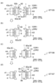
- a first modified example of the workpiece machining method will be described with reference to Fig. 30.
- the first step ST101 to the fourth step ST104 and the sixth step ST106 in the first modified example of the workpiece machining method are similar to the above-mentioned first step ST101 to the fourth step ST104 and the sixth step ST106, respectively. Therefore, in the first modified example of the workpiece machining method, repeated explanations of the first step ST101 to the fourth step ST104 and the sixth step ST106 will be omitted.
- the oxidized surface 911 of the workpiece 9 (more specifically, the oxidized surface 911a on the fourth direction DR4 side) is cut.
- the fifth step ST105 is a second cutting process.
- the second cutting process includes cutting the oxidized surface 911 of the workpiece 9 so that a machined surface 92 is formed on the workpiece 9 held by the second workpiece holding device 4. More specifically, the oxidized surface 911a on the fourth direction DR4 side of the workpiece 9 is cut to form a second machined surface 92a on the fourth direction DR4 side.
- the second cutting process includes bringing the cutting tool T1 into contact with the workpiece 9 while the second chuck body 41, which holds the workpiece 9 via the jaws 42, is rotating around the second axis AT.
- the workpiece 9 held by the second workpiece holding device 4 may be ground by the grinding tool T2 (grinding process).
- the first processing device 50 performs both cutting the oxidized surface 911a of the workpiece 9 using the cutting tool T1 and grinding the workpiece 9 (more specifically, the second machined surface 92a of the workpiece 9) using the grinding tool T2.
- the grinding process includes bringing the grinding tool T2 into contact with the workpiece 9 while the second chuck body 41, which holds the workpiece 9 via the jaws 42, is rotating around the second axis AT.
- the seventh step ST107 the second portion 96 of the workpiece 9 is machined.
- the seventh step ST107 is a workpiece machining process.
- the workpiece machining process (seventh step ST107) is performed in a state in which the machined surface 92 (more specifically, the second machined surface 92a) formed by cutting and grinding the oxidized surface of the workpiece 9 (more specifically, the oxidized surface on the fourth direction DR4 side of the workpiece 9) is held by the second holding surface 12 of the chuck soft jaw 1.
- the surface formed by grinding after cutting is considered to be one aspect of the machined surface 92.
- the workpiece machining process includes grinding the second portion 96 of the workpiece 9.
- the workpiece machining process includes bringing the grinding tool T2 into contact with the second portion 96 of the workpiece 9 while the chuck body 31, which holds the workpiece 9 via the chuck jaws 1, is rotating about the first axis AX.
- grinding Compared to cutting (more specifically, turning), grinding has a smaller depth of cut. Therefore, during grinding, it is sufficient for the workpiece 9 to be held with a relatively small gripping force by the second holding surface 12, which has a relatively low hardness.
- the grinding of the second portion 96 by the grinding tool T2 is performed with high accuracy.
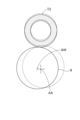
- the central axis AW of the workpiece 9 is eccentric from the first axis AX (in other words, the rotation axis of the chuck body 31).
- the grinding tool T2 is moved in the vertical direction based on the amount of eccentricity between the first axis AX and the central axis AW of the workpiece 9 and the rotation phase of the chuck body 31.
- the central axis AW of the workpiece 9 can be obtained, for example, by measuring the second cutting surface 92a (see FIG. 30(b)) with a touch sensor and analyzing the measurement result by a computer.
- a second modified example of the workpiece machining method will be described with reference to Fig. 32.
- the first step ST101 to the fourth step ST104 and the sixth step ST106 in the second modified example of the workpiece machining method are the same as the first step ST101 to the fourth step ST104 and the sixth step ST106 described above, respectively. Therefore, in the second modified example of the workpiece machining method, repeated explanations of the first step ST101 to the fourth step ST104 and the sixth step ST106 will be omitted.
- the oxidized surface 911 of the workpiece 9 (more specifically, the oxidized surface 911a on the fourth direction DR4 side) is cut.
- the fifth step ST105 is a second cutting process.
- the second cutting process includes cutting the oxidized surface 911 of the workpiece 9 so that a machined surface 92 is formed on the workpiece 9 held by the second workpiece holding device 4. More specifically, the oxidized surface 911a on the fourth direction DR4 side of the workpiece 9 is cut to form a second machined surface 92a on the fourth direction DR4 side.
- the second cutting process includes bringing the cutting tool T1 into contact with the workpiece 9 while the second chuck body 41, which holds the workpiece 9 via the jaws 42, is rotating around the second axis AT.
- an internal gear 96c may be formed on the workpiece 9 held by the second workpiece holding device 4.
- the internal gear 96c is formed using a skiving cutter T3.
- the first processing device 50 performs both cutting the oxidized surface 911a of the workpiece 9 using the cutting tool T1 and skiving the workpiece 9 using the skiving cutter T3.
- the skiving process includes bringing the skiving cutter T3, which rotates about the tool axis, into contact with the workpiece 9 while the second chuck body 41, which holds the workpiece 9 via the jaws 42, rotates about the second axis AT.
- the seventh step ST107 the second portion 96 of the workpiece 9 is machined.
- the seventh step ST107 is a workpiece machining process.
- the workpiece machining process (seventh step ST107) is performed in a state where the machined surface 92 (more specifically, the second machined surface 92a) formed by cutting the oxidized surface of the workpiece 9 (more specifically, the oxidized surface on the fourth direction DR4 side of the workpiece 9) is held by the second holding surface 12 of the chuck soft jaws 1.
- the workpiece machining process includes removing burrs 96b formed on the second portion 96 of the workpiece 9 (more specifically, the internal gear 96c of the workpiece 9).
- the burrs 96b are removed using a deburring tool T4.
- the workpiece machining process includes bringing the deburring tool T4 into contact with the burr 96b of the workpiece 9 while the chuck body 31, which holds the workpiece 9 via the chuck jaws 1, is rotating around the first axis AX.
- a third modified example of the workpiece machining method will be described with reference to Fig. 33.
- the first step ST101 to the fourth step ST104 and the sixth step ST106 in the third modified example of the workpiece machining method are the same as the first step ST101 to the fourth step ST104 and the sixth step ST106 described above, respectively. Therefore, in the third modified example of the workpiece machining method, repeated explanations of the first step ST101 to the fourth step ST104 and the sixth step ST106 will be omitted.
- the oxidized surface 911 of the workpiece 9 (more specifically, the oxidized surface 911a on the fourth direction DR4 side) is cut.
- the fifth step ST105 is a second cutting process.
- the second cutting process includes cutting the oxidized surface 911 of the workpiece 9 so that a machined surface 92 is formed on the workpiece 9 held by the second workpiece holding device 4. More specifically, the oxidized surface 911a on the fourth direction DR4 side of the workpiece 9 is cut to form a second machined surface 92a on the fourth direction DR4 side.
- the second cutting process includes bringing the cutting tool T1 into contact with the workpiece 9 while the second chuck body 41, which holds the workpiece 9 via the jaws 42, is rotating around the second axis AT.
- a gear 96d such as an internal gear or an external gear may be formed on the workpiece 9 held by the second workpiece holding device 4.
- the gear 96d is formed using a gear cutting tool T5 (e.g., a skiving cutter, a bob cutter, etc.). More specifically, the internal gear may be formed using a skiving cutter, and the external gear may be formed using a bob cutter.
- the first processing device 50 performs both cutting the oxidized surface 911a of the workpiece 9 using the cutting tool T1 and forming the gear 96d on the workpiece 9 using the gear cutting tool T5.
- the gear cutting process includes contacting the gear cutting tool T5, which rotates about the tool axis, with the workpiece 9 while the second chuck body 41, which holds the workpiece 9 via the jaws 42, rotates about the second axis AT.
- the seventh step ST107 the second portion 96 of the workpiece 9 is machined.
- the seventh step ST107 is a workpiece machining process.
- the workpiece machining process (seventh step ST107) is performed in a state where the machined surface 92 (more specifically, the second machined surface 92a) formed by cutting the oxidized surface of the workpiece 9 (more specifically, the oxidized surface on the fourth direction DR4 side of the workpiece 9) is held by the second holding surface 12 of the chuck soft jaws 1.
- the workpiece machining process includes forming holes 96h, recesses, etc. in the second portion 96 of the workpiece 9.
- the holes 96h, recesses, etc. are formed, for example, using a mill tool T6 (for example, a drill).
- a gear 96d is formed on the workpiece 9 by a gear cutting tool T5 before the execution of the seventh step ST107.
- the seventh step ST107 may include detecting the phase of the gear 96d and forming a hole 96h, a recess, etc., at a desired position using a milling tool T6 based on the detected phase.
- the workpiece machining method includes a step of transferring the workpiece 9 between the first workpiece holding device 3 and the second workpiece holding device 4.
- the step of transferring the workpiece 9 between the first workpiece holding device 3 and the second workpiece holding device 4 is omitted.
- the first step ST101 and the second step ST102 in the fourth modified example of the workpiece machining method are similar to the first step ST101 and the second step ST102 described above. Therefore, in the fourth modified example of the workpiece machining method, repeated explanations of the first step ST101 and the second step ST102 will be omitted.
- the first portion 95 of the workpiece 9 (more specifically, the oxidized surface 911b on the third direction DR3 side of the workpiece 9) is cut. By cutting the first portion 95 of the workpiece 9, a machined surface 92 is formed.
- the third step ST103 is the first cutting process.
- the first portion 95 of the workpiece 9 is cut while the oxidized surface 911 of the workpiece 9 (more specifically, the oxidized surface 911a on the fourth direction DR4 side of the workpiece 9) is held by the first holding surface 11 of the chuck jaw 1.
- the first cutting process includes bringing the cutting tool T1 into contact with the first portion 95 of the workpiece 9 while the chuck body 31, which holds the workpiece 9 via the chuck jaws 1, is rotating about the first axis AX.
- the end of the workpiece 9 on the third direction DR3 side may be pressed by the core support 48.
- the fourth step ST104' As shown in FIG. 34(b), in the fourth step ST104', the holding position of the workpiece 9 by the chuck jaws 1 is changed.
- the fourth step ST104' is a holding position changing process.
- the holding position change process (fourth step ST104') includes (1) moving the chuck jaws 1 in a direction away from the workpiece 9, (2) inverting the workpiece 9, and (3) moving the second holding surface 12 of the chuck jaws 1 in a direction approaching the cutting surface 92 of the workpiece 9.
- the cutting surface 92 of the workpiece 9 is held by the second holding surface 12 of the chuck jaws 1.
- the second portion 96 of the workpiece 9 is machined.
- the fifth step ST105' is a workpiece machining process.
- the workpiece machining process (fifth step ST105') is performed in a state in which the machined surface 92 formed by cutting the oxidized surface of the workpiece 9 is held by the second holding surface 12 of the chuck soft jaws 1.
- the second holding surface 12 has a relatively low hardness, so the machined surface 92 of the workpiece 9 is prevented from being damaged by the second holding surface 12.
- the workpiece machining process includes cutting the second portion 96 of the workpiece 9.
- the workpiece machining process includes bringing the cutting tool T1 into contact with the workpiece 9 while the chuck body 31, which holds the workpiece 9 via the chuck jaws 1, is rotating around the first axis AX.
- the workpiece machining process may include forming a gear 96d, such as an internal gear or an external gear, on the workpiece 9 held by the first workpiece holding device 3.
- the gear 96d is formed using a gear cutting tool T5 (e.g., a skiving cutter, a bob cutter, etc.).
- the workpiece machining process includes contacting the gear cutting tool T5, which rotates about the tool axis, with the workpiece 9 in a state in which the chuck body 31, which holds the workpiece 9 via the chuck soft jaws 1, is rotating about the first axis AX.
- a first portion 95 of the workpiece 9 is cut while the outer surface of the workpiece 9 is held by the first holding surface 11 of the chuck jaws 1.
- a first portion 95 of the workpiece 9 is cut while the inner surface 91n of the workpiece 9 is held by the first holding surface 11 of the chuck jaws 1.
- the seventh step ST107 (or the fifth step ST105') the second portion 96 of the workpiece 9 is machined while the outer surface of the workpiece 9 is held by the second holding surface 12 of the chuck soft jaws 1.
- the seventh step ST107 (or the fifth step ST105') the second portion 96 of the workpiece 9 is machined while the inner surface of the workpiece 9 is held by the second holding surface 12 of the chuck soft jaws 1.
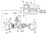
- Hybrid machine tool 2 A hybrid machine tool 2 in the first embodiment will be described with reference to Figs. 1 to 42.
- Figs. 36 and 37 are schematic perspective views showing the hybrid machine tool 2 in the first embodiment.
- Figs. 38 and 39 are schematic perspective views showing the hybrid machine tool 2 in a first modified example of the first embodiment.
- Figs. 40 to 42 are diagrams showing a state in which the control device 7 can transmit control commands to a plurality of controlled devices.
- the hybrid machine tool 2 in the first embodiment includes a plurality of processing devices 5 that form the chuck jaws, a first work holding device 3, and a control device 7 that controls the plurality of processing devices 5 and the first work holding device 3.
- the multiple processing devices 5 form the chuck raw jaws 1 (see FIG. 37) from the raw material block BL (see FIG. 36) attached to the chuck body 31. More specifically, the multiple processing devices 5 form the chuck raw jaws 1 (see FIG. 16 or FIG. 20) from the raw material block BL (see FIG. 13) attached to the chuck body 31, the chuck raw jaws having a first holding surface 11 that holds the oxidized surface of the workpiece and a second holding surface 12 that holds the machined surface of the workpiece.
- the first work holding device 3 holds the work 9 via the chuck jaws 1.
- the first work holding device 3 has a chuck body 31 that supports the chuck jaws 1, a first drive device 34 that moves the chuck jaws 1, and a first rotation drive device 36.
- the first drive device 34 moves the chuck jaws 1 in a first direction DR1 away from the first axis AX (more specifically, a radial direction away from the first axis AX) or in a second direction DR2 toward the first axis AX.
- the first rotation drive device 36 rotates the chuck body 31 around the first axis AX.
- the first rotation drive device 36 rotates the chuck body 31, the chuck jaws 1 supported by the chuck body 31, and the workpiece 9 held by the chuck jaws 1 together around the first axis AX.
- the multiple processing devices 5 include a first processing device 50 and a second processing device 60.
- the first processing device 50 can hold a cutting tool T1 (see FIG. 16 or FIG. 20).
- the first processing device (more specifically, the cutting tool T1 held by the first processing device 50) cuts the raw material block BL attached to the chuck body 31, thereby forming a second holding surface 12 on the raw material block BL.
- the first processing device (more specifically, the cutting tool T1 held by the first processing device 50) cuts the raw material block BL attached to the chuck body 31, thereby forming a cutting surface BL1 on the raw material block BL, which serves as the basis for the first holding surface 11.
- the second processing device 60 processes the raw material block BL (more specifically, the above-mentioned cutting surface BL1) attached to the chuck body 31 to form a first holding surface 11 on the raw material block BL, the first holding surface 11 having a hardness higher than the hardness of the second holding surface 12.
- the second processing device 60 may form a first holding surface 11 (in other words, a hardened first holding surface 11) having a higher hardness than the second holding surface 12 by irradiating a raw material block BL (more specifically, the above-mentioned cutting surface BL1) with laser light LB.
- the second processing device 60 may form a first holding surface 11 having a hardness higher than that of the second holding surface 12 by adding a metal material N having a higher hardness than the material constituting the raw material block BL to the raw material block BL (more specifically, the above-mentioned cutting surface BL1).
- the hybrid machine tool 2 in the first embodiment has a first workpiece holding device 3 that holds a workpiece 9 via the chuck jaws 1, and a plurality of processing devices 5 that form a first holding surface 11 and a second holding surface 12 on the chuck jaws 1. Therefore, the shaping of the chuck jaws 1 and the processing of the workpiece 9 can be performed using the same hybrid machine tool 2.
- the hybrid machine tool 2 in the first embodiment forms a chuck jaw 1 having a first holding surface 11 (more specifically, the first holding surface 11 having a relatively high hardness) with a hardness suitable for holding the first surface 91 (more specifically, the oxidized surface 911) of the workpiece 9, and a second holding surface 12 (more specifically, the second holding surface 12 having a relatively low hardness) with a hardness suitable for holding the machined surface 92 of the workpiece 9.
- the chuck body 31 supports the chuck jaw 1, the second chuck jaw 1B, and the third chuck jaw 1C. Additionally, the chuck body 31 may support a fourth chuck jaw.
- the shape and structure of the second chuck jaw 1B are similar to those of the chuck jaw 1, and the shape and structure of the third chuck jaw 1C are similar to those of the chuck jaw 1. Therefore, repeated explanations of the second chuck jaw 1B and the third chuck jaw 1C will be omitted.
- the first holding surface 11 of the chuck jaw 1, the first holding surface 11 of the second chuck jaw 1B, and the first holding surface 11 of the third chuck jaw 1C cooperate to hold the first surface 91 (more specifically, the oxidized surface 911) of the workpiece 9.
- the second holding surface 12 of the chuck jaw 1, the second holding surface 12 of the second chuck jaw 1B, and the second holding surface 12 of the third chuck jaw 1C cooperate to hold the machined surface 92 of the workpiece 9.
- the hardness of the first holding surface 11 is higher than the hardness of the second holding surface 12 in each of the chuck jaw 1, the second chuck jaw 1B, and the third chuck jaw 1C.
- the first work holding device 3 has a chuck body 31 and a first driving device 34.
- the chuck body 31 may have a movable part 32 to which the chuck soft jaws 1 are fixed, and a base part 33 that movably supports the movable part 32.
- the first driving device 34 can move the chuck soft jaws 1 and the movable part 32 relative to the base part 33 in the first direction DR1 or the second direction DR2.
- the first drive device 34 simultaneously moves the chuck jaw 1, the second chuck jaw 1B, and the third chuck jaw 1C in a direction away from the first axis AX (or in a direction toward the first axis AX).
- the hybrid machine tool 2 may have a first moving device 81 (more specifically, a Z-axis servo motor) that moves the first work holding device 3 in a direction parallel to the first axis AX.
- a first moving device 81 more specifically, a Z-axis servo motor
- the hybrid machine tool 2 is equipped with a second work holding device 4 .
- the second work holding device 4 is capable of receiving the work 9 from the first work holding device 3.
- the second work holding device 4 is also capable of delivering the work 9 to the first work holding device 3. Note that the receiving of the work from the first work holding device 3 and the delivery of the work to the first work holding device 3 may each be performed automatically, or may be performed manually.
- the second workpiece holding device 4 has a second chuck body 41, a second drive device 44, and a second rotation drive device 46.
- the second chuck body 41 supports jaws 42 (more specifically, soft jaws 42a) capable of holding the workpiece 9.
- the second drive unit 44 is capable of moving the claw 42 (more specifically, the raw claw 42a) in a direction away from the second axis AT, and is capable of moving the claw 42 (more specifically, the raw claw 42a) in a direction toward the second axis AT.
- the second rotation drive device 46 rotates the second chuck body 41 around the central axis of the second chuck body 41 (in other words, the second axis AT).
- the second axis AT which is the central axis of the second chuck body 41, is coaxial with the first axis AX, which is the central axis of the chuck body 31, or is parallel to the first axis AX.
- the hybrid machine tool 2 may have a second moving device 82 (more specifically, a Z-axis servo motor) that moves the second work holding device 4 in a direction parallel to the central axis of the second chuck body 41.
- a second moving device 82 more specifically, a Z-axis servo motor
- the hybrid machine tool 2 has a second workpiece holding device 4, the hybrid machine tool 2 can be used to perform the workpiece machining method described with reference to Figures 22 to 33.
- the first processing device 50 has a first head 52 that holds a tool T such as a cutting tool T1, and a first head moving device 55 that moves the first head 52.
- the first head moving device 55 may be a device capable of moving the first head 52 three-dimensionally.
- the first head moving device 55 has a first motor 55a (more specifically, an X-axis servo motor) that moves the first head 52 in a direction parallel to the vertical axis, a second motor 55b (more specifically, a Z-axis servo motor) that moves the first head 52 in a direction parallel to the first axis AX, and a third motor 55c (more specifically, a Y-axis servo motor) that moves the first head 52 in a direction perpendicular to both the vertical axis and the first axis AX.
- a first motor 55a (more specifically, an X-axis servo motor) that moves the first head 52 in a direction parallel to the vertical axis
- a second motor 55b more specifically, a Z-axis servo motor
- a third motor 55c (more specifically, a Y-axis servo motor) that moves the first
- the first machining device 50 may have a rotation drive device 57 that rotates the tool T around the tool axis.
- the second processing device 60 includes a laser irradiation device 61 that heat-treats the raw material block BL.
- the laser irradiation device 61 irradiates the raw material block BL (more specifically, the cutting surface BL1 of the raw material block BL) with laser light LB, thereby forming a first holding surface 11 in the raw material block BL that has a hardness higher than the hardness of the original surface of the raw material block BL.
- the second processing device 60 has a second head 62 that emits laser light and a second head moving device 64 that moves the second head 62.
- the second head moving device 64 may be a device capable of moving the second head 62 two-dimensionally or three-dimensionally.
- the second head moving device 64 has a fourth motor 64a (more specifically, an X-axis servo motor) that moves the second head 62 in a direction parallel to the vertical axis, and a fifth motor 64b (more specifically, a Z-axis servo motor) that moves the second head 62 in a direction parallel to the first axis AX.
- the second head moving device 64 may have a sixth motor 64c that tilts the second head 62 around an axis parallel to the horizontal plane.
- the laser irradiation device 61 is used to form the chuck jaws 1. Additionally, the laser irradiation device 61 may be used to process the workpiece 9.
- the second processing device 60 may include an additional processing device 66 instead of (or in addition to) the laser irradiation device 61.
- the additional processing device 66 adds a metal material having a higher hardness than the raw material block BL to the raw material block BL.
- the additional processing device 66 has a laser head 67 that emits a laser beam LB and a nozzle 68 that emits a metal powder P toward the laser beam LB emitted from the laser head 67.
- the additional processing device 66 supplies the metal powder P toward the raw material block BL (more specifically, the cutting surface BL1 of the raw material block BL) and irradiates the raw material block BL (more specifically, the cutting surface BL1 of the raw material block BL) with the laser beam LB.
- the metal powder P heated by the energy of the laser beam LB melts, and the molten metal adheres to the raw material block BL (more specifically, the cutting surface BL1 of the raw material block BL).
- the first holding surface 11 having a hardness higher than that of the second holding surface 12 is formed on the raw material block BL (more specifically, the cutting surface BL1 of the raw material block BL).
- the additional processing device 66 has a third head moving device 69 that moves the laser head 67 and the nozzle 68.
- the third head moving device 69 may be a device capable of moving the laser head 67 and the nozzle 68 two-dimensionally or three-dimensionally.
- the third head moving device 69 has a seventh motor 69a (more specifically, an X-axis servo motor) that moves the laser head 67 and the nozzle 68 in a direction parallel to the vertical axis, and an eighth motor 69b (more specifically, a Z-axis servo motor) that moves the laser head 67 and the nozzle 68 in a direction parallel to the first axis AX.
- the third head moving device 69 may have a ninth motor 69c that tilts the laser head 67 and the nozzle 68 around an axis parallel to the horizontal plane.
- the hybrid machine tool 2 comprises a base 80.
- the base 80 supports the first workholding device 3, the first processing device 50, and the second processing device 60. Additionally, the base 80 may support the second workholding device 4.
- Control device 7 36, the hybrid machine tool 2 includes a control device 7.
- the control device 7 may be configured by one computer, or may be configured by multiple computers.
- the control device 7 includes a processor 71, a storage device 72 (more specifically, a memory), a communication circuit 73, and an input device 74 (e.g., a display 742 with a touch panel).
- the processor 71, the storage device 72, the communication circuit 73, and the input device 74 are connected to each other via a bus 75.
- Data required for forming the chuck jaws 1 and machining the workpiece 9 e.g., shape data of the chuck jaws 1 or the workpiece 9, machining position data of the chuck jaws 1 or the workpiece 9, etc.
- the input device 74 is not limited to the display 742 with a touch panel.
- the control device 7 may include an input device 74 such as a button, a switch, a lever, a pointing device, a keyboard, etc., and a display that displays the data input to the input device 74 or other information.
- the processor 71 generates a control signal by executing a machining program 722 stored in the storage device 72 based on data input to the control device 7.
- the communication circuit 73 also transmits the control signal to the controlled equipment (e.g., the first work holding device 3, the second work holding device 4, the multiple machining devices 5, the first moving device 81 that moves the first work holding device 3, and/or the second moving device 82 that moves the second work holding device 4).
- the processor 71 executes the machining program 722, allowing the control device 7 to control the controlled equipment.
- the machining program 722 may include a soft jaw forming program 722a and a workpiece machining program 722b. More specifically, the storage device 72 may store a soft jaw forming program 722a executed by the control device 7 and a workpiece machining program 722b executed by the control device 7.
- the control device 7 can execute a first holding surface forming mode by executing the soft jaw forming program 722a.
- the first holding surface forming mode is a mode including forming, on the raw material block BL attached to the chuck body 31, a first holding surface 11 having a hardness higher than the hardness of the original surface of the raw material block BL, using the second processing device 60.
- the first holding surface forming mode will be described in more detail.
- the control device 7 transmits a first rotation command R1 generated by executing the raw jaw forming program 722a to the first rotation drive device 36 of the first workpiece holding device 3.
- the control device 7 also transmits a first cutting command J1 generated by executing the raw jaw forming program 722a to the first processing device 50.
- the first rotation drive device 36 that receives the first rotation command R1 rotates the chuck body 31 and the raw material block BL attached to the chuck body 31 around the first axis AX.
- the first processing device 50 that receives the first cutting command J1 uses the cutting tool T1 to form a cutting surface BL1 on the raw material block BL rotating around the first axis AX. Note that if the first holding surface 11 is formed by processing the original surface of the raw material block BL itself, the process of forming the cutting surface BL1 may be omitted.
- the control device 7 transmits a first holding surface formation command F1, which is generated by executing the raw jaw forming program 722a, to the second processing device 60.
- the second processing device 60 which receives the first holding surface formation command F1, processes the raw material block BL (more specifically, the cutting surface BL1) to form a first holding surface 11 having a hardness higher than the hardness of the original surface of the raw material block BL.
- the laser irradiation device 61 when the second processing device 60 includes a laser irradiation device 61, the laser irradiation device 61, which receives a first holding surface formation command F1, irradiates the raw material block BL (more specifically, the cutting surface BL1) with laser light LB (see FIG. 15).
- the raw material block BL (more specifically, the cutting surface BL1) is heat-treated (more specifically, hardened) by the laser light LB, and as a result, the hardness of the cutting surface BL1 increases, and a first holding surface 11 having a relatively high hardness is formed from the raw material block BL (more specifically, the cutting surface BL1).
- the additional processing device 66 that receives the first holding surface formation command F1 adds a metal material N having a higher hardness than the raw material block BL to the raw material block BL (more specifically, the cutting surface BL1) (see FIG. 18).
- the first rotation drive device 36 of the first workpiece holding device 3 may continuously or intermittently rotate the chuck body 31 and the raw material block BL attached to the chuck body 31 around the first axis AX.
- the control device 7 can execute a second holding surface forming mode by executing the soft jaw forming program 722a.
- the second holding surface forming mode is a mode in which the second holding surface 12 is formed on the raw material block BL attached to the chuck body 31 by using the first processing device 50.
- the second holding surface forming mode will be described in more detail.
- the control device 7 transmits a second rotation command R2 generated by executing the raw jaw forming program 722a to the first rotation drive device 36 of the first work holding device 3.
- the control device 7 also transmits a second cutting command J2 generated by executing the raw jaw forming program 722a to the first processing device 50.
- the first rotation drive device 36 which receives the second rotation command R2, rotates the chuck body 31 and the raw material block BL attached to the chuck body 31 around the first axis AX.
- the first processing device 50 which receives the second cutting command J2, uses the cutting tool T1 to form a second holding surface 12 on the raw material block BL rotating around the first axis AX.
- the control device 7 can execute the first machining mode by executing the workpiece machining program 722b.
- the first machining mode is a mode in which the workpiece 9 held by the first holding surface 11 of the chuck soft jaws 1 is machined using the first machining device 50.
- the first machining mode is executed in a state in which the oxidized surface 911 of the workpiece 9 is held by the first holding surface 11 of the chuck soft jaws 1. The first machining mode will be described in more detail.
- the control device 7 transmits a first machining command C1 generated by executing the workpiece machining program 722b to the first machining device 50.
- the first machining device 50 receives the first machining command C1 and machines the workpiece 9 held on the first holding surface 11 of the chuck jaws 1.
- control device 7 transmits a rotation command (more specifically, a third rotation command R3) generated by executing the workpiece machining program 722b to the first rotation drive device 36 of the first workpiece holding device 3.
- the control device 7 also transmits a first machining command C1 generated by executing the workpiece machining program 722b to the first machining device 50.
- the first rotation drive device 36 that receives the rotation command (more specifically, the third rotation command R3) rotates the chuck body 31, the chuck soft jaws 1 held by the chuck body 31, and the workpiece 9 held by the first holding surface 11 of the chuck soft jaws 1 around the first axis AX.
- the first machining device 50 that receives the first machining command C1 uses the cutting tool T1 to cut the first portion 95 (more specifically, the oxidized surface 911b on the third direction DR3 side of the workpiece 9) of the workpiece 9 that rotates around the first axis AX. In this way, a machined surface 92 (more specifically, a first machined surface 92b) is formed on the workpiece 9.
- the control device 7 can execute the second machining mode by executing the workpiece machining program 722b.
- the second machining mode is a mode in which the workpiece 9 held by the second holding surface 12 of the chuck soft jaws 1 is machined using the first machining device 50.
- the second machining mode is executed in a state in which the cutting surface 92 of the workpiece 9 is held by the second holding surface 12 of the chuck soft jaws 1. The second machining mode will be described in more detail.
- control device 7 transmits a second machining command C2 generated by executing the workpiece machining program 722b to the first machining device 50.
- the first machining device 50 receives the second machining command C2 and machines the workpiece 9 held on the second holding surface 12 of the chuck jaws 1.
- the control device 7 transmits a rotation command (more specifically, a fourth rotation command R4) generated by executing the workpiece machining program 722b to the first rotation drive device 36 of the first workpiece holding device 3.
- the control device 7 also transmits a second machining command C2 generated by executing the workpiece machining program 722b to the first machining device 50.
- the first rotation drive device 36 that receives the rotation command (more specifically, the fourth rotation command R4) rotates the chuck body 31, the chuck soft jaws 1 held by the chuck body 31, and the workpiece 9 held on the second holding surface 12 of the chuck soft jaws 1 around the first axis AX.
- the first machining device 50 that receives the second machining command C2 uses a tool T such as a cutting tool T1 to machine the workpiece 9 rotating around the first axis AX.
- the first machining device 50 holds a cutting tool T1.
- the first machining device 50 that receives the second machining command C2 uses the cutting tool T1 to cut the workpiece 9 that rotates around the first axis AX.
- the first machining device 50 may hold a grinding tool T2.
- the first machining device 50 that receives the second machining command C2 uses the grinding tool T2 to grind the workpiece 9 rotating around the first axis AX.
- the first machining device 50 may hold a milling tool T6.
- the first machining device 50 that receives the second machining command C2 mills the workpiece 9 using the milling tool T6. Note that the milling is performed in a state where the rotation of the workpiece 9 about the first axis AX is stopped.
- the first machining device 50 may hold a gear cutting tool T5.
- the first machining device 50 receiving the second machining command C2 uses the gear cutting tool T5 to form a gear 96d on the workpiece 9 rotating around the first axis AX.
- the first rotary drive device 36 receiving the rotation command rotates the workpiece 9 around the first axis AX
- the first machining device 50 receiving the second machining command C2 rotates the gear cutting tool T5 around the tool axis
- the first machining device 50 receiving the second machining command C2 brings the gear cutting tool T5 into contact with the workpiece 9.
- the gear 96d is formed on the workpiece 9 by contact between the workpiece 9 rotating around the first axis AX and the gear cutting tool T5 rotating around the tool axis.
- control device 7 may execute the first transfer mode, the third processing mode, and the second transfer mode, which will be described later, after executing the first processing mode and before executing the second processing mode.
- the control device 7 executes the workpiece machining program 722b to execute a first transfer mode.
- the first transfer mode is a mode in which the workpiece 9 is transferred from the first workpiece holding device 3 to the second workpiece holding device 4. The first transfer mode will be described in more detail.
- the control device 7 transmits a first movement command M1 generated by executing the workpiece machining program 722b to at least one of the first movement device 81 and the second movement device 82.
- the movement device that receives the first movement command M1 moves one of the first workpiece holding device 3 and the second workpiece holding device 4 in a direction approaching the other of the first workpiece holding device 3 and the second workpiece holding device 4.
- the control device 7 transmits a first holding command H1 generated by executing the workpiece machining program 722b to the second drive device 44.
- the second drive device 44 which receives the first holding command H1, moves the jaws 42 (more specifically, the soft jaws 42a) in a direction approaching the workpiece 9 (more specifically, the first cutting surface 92b of the workpiece 9). In this way, the workpiece 9 (more specifically, the first cutting surface 92b of the workpiece 9) is held by the jaws 42 of the second workpiece holding device 4.
- the control device 7 transmits a first hold release command E1, which is generated by executing the workpiece machining program 722b, to the first driving device 34.
- the first driving device 34 which receives the first hold release command E1, moves the chuck soft jaws 1 in a direction away from the workpiece 9 (more specifically, the oxidized surface 911 of the workpiece 9). In this way, the first workpiece holding device 3 releases the hold of the workpiece 9.
- the control device 7 can execute the workpiece machining program 722b to execute the third machining mode.
- the third machining mode is a mode in which the first machining device 50 is used to machine the workpiece 9 held by the jaws 42 (more specifically, the soft jaws 42a) of the second workpiece holding device 4. The third machining mode will be described in more detail.
- control device 7 transmits a third machining command C3 generated by executing the workpiece machining program 722b to the first machining device 50.
- the first machining device 50 that receives the third machining command C3 machines the workpiece 9 held by the second workpiece holding device 4.
- control device 7 transmits a rotation command (more specifically, the fifth rotation command R5) generated by executing the workpiece machining program 722b to the second rotation drive device 46 of the second workpiece holding device 4.
- the control device 7 also transmits a third machining command C3 generated by executing the workpiece machining program 722b to the first machining device 50.
- the second rotation drive device 46 which receives the rotation command (more specifically, the fifth rotation command R5), rotates the second chuck body 41, the jaws 42 held by the second chuck body 41, and the workpiece 9 held by the jaws 42 around the second axis AT.
- the first machining device 50 which receives the third machining command C3, uses the cutting tool T1 to cut the third portion 97 (more specifically, the oxidized surface 911 of the workpiece 9) of the workpiece 9 rotating around the second axis AT. In this way, a machined surface 92 (more specifically, the second machined surface 92a on the fourth direction DR4 side) is formed on the workpiece 9.
- the control device 7 may execute the third machining mode to grind the workpiece 9 (e.g., the machined surface 92 of the workpiece). More specifically, the second rotation drive device 46 that receives the fifth rotation command R5 may rotate the workpiece 9 about the second axis AT, and the first machining device 50 that receives the third machining command C3 from the control device 7 may use the grinding tool T2 to grind the workpiece 9 rotating about the second axis AT.
- the control device 7 may execute the third machining mode to grind the workpiece 9 (e.g., the machined surface 92 of the workpiece). More specifically, the second rotation drive device 46 that receives the fifth rotation command R5 may rotate the workpiece 9 about the second axis AT, and the first machining device 50 that receives the third machining command C3 from the control device 7 may use the grinding tool T2 to grind the workpiece 9 rotating about the second axis AT.
- the control device may execute the third machining mode to form an internal gear 96c on the workpiece 9. More specifically, the second rotation drive device 46 receiving the fifth rotation command R5 may rotate the workpiece 9 around the second axis AT, the first machining device 50 receiving the third machining command C3 may rotate the skiving cutter T3 around the tool axis, and the first machining device 50 receiving the third machining command C3 may bring the skiving cutter T3 into contact with the inner peripheral surface of the workpiece 9.
- the control device 7 can execute the second transfer mode by executing the workpiece machining program 722b.
- the second transfer mode is a mode in which the workpiece 9 is transferred from the second workpiece holding device 4 to the first workpiece holding device 3. The second transfer mode will be described in more detail.
- the control device 7 transmits a second movement command M2 generated by executing the workpiece machining program 722b to at least one of the first movement device 81 and the second movement device 82.
- the movement device that receives the second movement command M2 moves one of the first workpiece holding device 3 and the second workpiece holding device 4 in a direction approaching the other of the first workpiece holding device 3 and the second workpiece holding device 4.
- the control device 7 transmits a second holding command H2 generated by executing the workpiece machining program 722b to the first driving device 34.
- the first driving device 34 receiving the second holding command H2 moves the second holding surface 12 of the chuck jaws 1 in a direction approaching the cutting surface 92 of the workpiece 9 (more specifically, the second cutting surface 92a on the fourth direction DR4 side of the workpiece 9). In this way, the cutting surface 92 of the workpiece 9 is held by the second holding surface 12 of the chuck jaws 1.
- the control device 7 transmits a second hold release command E2, which is generated by executing the workpiece machining program 722b, to the second drive device 44.
- the second drive device 44 which receives the second hold release command E2, moves the jaws 42 (more specifically, the soft jaws 42a) in a direction away from the workpiece 9. In this way, the second workpiece holding device 4 releases the hold of the workpiece 9.
- the process of transferring the work 9 from the first work holding device 3 to the second work holding device 4 is performed automatically using the first work holding device 3 and the second work holding device 4.
- at least a part of the transfer process may be performed manually.
Landscapes
- Engineering & Computer Science (AREA)
- Mechanical Engineering (AREA)
- Physics & Mathematics (AREA)
- Optics & Photonics (AREA)
- Gripping On Spindles (AREA)
- Turning (AREA)
- Laser Beam Processing (AREA)
Abstract
Description
本明細書において、第1ワーク保持装置3のチャック本体31の中心軸である第1軸AXから離れる方向を「第1方向DR1」と定義する。また、第1ワーク保持装置3のチャック本体31の中心軸である第1軸AXに近づく方向を「第2方向DR2」と定義する。
図1乃至図12を参照して、第1の実施形態におけるチャック生爪1について説明する。図1乃至図3は、第1の実施形態におけるチャック生爪1が、チャック本体31に支持されている様子を模式的に示す概略断面図である。なお、図2には、ワーク9Aが、チャック生爪1の第1保持面11に保持された様子が示され、図3には、ワーク9Aが、チャック生爪1の第2保持面12に保持された様子が示されている。図4は、第1の実施形態におけるチャック生爪1を模式的に示す概略断面図である。図5および図6は、第1の実施形態の第1変形例におけるチャック生爪1が、チャック本体31に支持されている様子を模式的に示す概略断面図である。なお、図5には、ワーク9Bが、チャック生爪1の第1保持面11に保持された様子が示され、図6には、ワーク9Bが、チャック生爪1の第2保持面12に保持された様子が示されている。図7は、第1の実施形態の第1変形例におけるチャック生爪1を模式的に示す概略断面図である。図8は、第1の実施形態の第1変形例におけるチャック生爪1を模式的に示す概略斜視図である。図9および図10は、第1の実施形態の第2変形例におけるチャック生爪1が、チャック本体31に支持されている様子を模式的に示す概略断面図である。なお、図9には、ワーク9Cが、チャック生爪1の第1保持面11に保持された様子が示され、図10には、ワーク9Cが、チャック生爪1の第2保持面12に保持された様子が示されている。図11は、第1の実施形態の第3変形例におけるチャック生爪1が、チャック本体31に支持されている様子を模式的に示す概略断面図である。図12は、第1の実施形態の第4変形例におけるチャック生爪1が、チャック本体31に支持されている様子を模式的に示す概略断面図である。
続いて、図1乃至図12を参照して、第1の実施形態におけるチャック生爪1において採用可能な任意付加的な構成について説明する。
図2に記載の例において、第1保持面11は、例えば、ワーク9Aの酸化表面911を保持する面である。ワーク9Aの酸化表面911は、細かな凹凸を有する。凹凸を有する酸化表面911と、第1保持面11との間のスリップを防止するため、当該酸化表面911は第1保持面11によって強い力で保持される必要がある。第1保持面11が、相対的に高い硬度を有する面である場合、酸化表面911に強い力で接触する第1保持面11が、酸化表面911によって傷つけられることが抑制される。よって、チャック生爪1の耐久性能が向上し、チャック生爪1の寿命を長くすることができる。
図3に記載の例において、第2保持面12は、ワーク9Aの切削加工面92を保持する面である。ワーク9Aの切削加工面92は、ワーク9Aの酸化表面911(図2を参照。)と比較して、相対的に滑らかな面である。第2保持面12が、相対的に低い硬度を有する面である場合、ワーク9Aの切削加工面92が、第2保持面12によって傷つけられることが抑制される。
図4に記載の例では、チャック生爪1は、チャック本体31に取り付けられる基部14を有する。基部14は、チャック本体31に形成された第2の凹凸部312に係合する第1の凹凸部142を有していてもよい。図3に記載の例では、第2の凹凸部312に対する第1の凹凸部142の相対位置を調整することにより、チャック本体31の可動部32に対するチャック生爪1の取り付け位置を調整可能である。チャック生爪1は、ボルト等の固定部材を介して、チャック本体31に取り付けられる。図4に記載の例では、チャック生爪1に、ボルト等の固定部材を受容可能な貫通穴部15が形成されている。
図3に記載の例では、第2保持面12は、第1軸AXに沿う方向において、第1保持面11と基部14との間に配置されている。
チャック生爪1における第1保持面11および第2保持面12の配置は、図2乃至図4に記載の例に限定されない。図5乃至図8を参照して、チャック生爪1の第1変形例について説明する。
図9および図10を参照して、チャック生爪1の第2変形例について説明し、図11を参照して、チャック生爪1の第3変形例について説明する。
図12を参照して、チャック生爪1の第4変形例について説明する。図1乃至図11に記載の例では、チャック生爪1が有する第1保持面11の数が1つであり、チャック生爪1が有する第2保持面12の数が1つである。代替的に、図12に例示されるように、チャック生爪1は、複数の第1保持面11を有していてもよい。また、図12に例示されるように、チャック生爪1は、複数の第2保持面12を有していてもよい。複数の第1保持面11の各々の硬度は、複数の第2保持面12の各々の硬度よりも高い。図12に記載の例では、第1軸AXに沿う方向において、第1保持面11と第2保持面12とが交互に配置されている。
図1乃至図21を参照して、第1の実施形態におけるチャック生爪の成形方法について説明する。図13は、取付工程が実行された後の状態を模式的に示す概略断面図である。図14は、切削工具T1によって原材ブロックBLが切削されている様子を模式的に示す概略断面図である。図15は、原材ブロックBLに第1保持面11が形成される様子を模式的に示す概略断面図である。図16は、原材ブロックBLに第2保持面12が形成される様子を模式的に示す概略断面図である。図17は、チャック生爪の成形方法の変形例において、切削工具T1によって原材ブロックBLが切削されている様子を模式的に示す概略断面図である。図18は、チャック生爪の成形方法の変形例において、原材ブロックBLに第1保持面11が形成される様子を模式的に示す概略断面図である。図19は、第1保持面11に凹凸111が形成される様子を模式的に示す概略断面図である。図20は、チャック生爪の成形方法の変形例において、原材ブロックBLに第2保持面12が形成される様子を模式的に示す概略断面図である。図21は、第1の実施形態におけるチャック生爪の成形方法の一例を示すフローチャートである。
図13、図17乃至図20を参照して、チャック生爪の成形方法の変形例について説明する。図13に例示されるように、第1ステップST1において、チャック本体31(より具体的には、チャック本体31の可動部32)に、原材ブロックBLが取り付けられる。第1ステップST1は、取付工程である。取付工程については、説明済みであるため、取付工程についての繰り返しとなる説明は省略する。
図1乃至図35を参照して、第1の実施形態におけるワーク加工方法について説明する。図22は、チャック生爪1にワーク9が取り付けられた後の様子を模式的に示す図である。図23は、ワーク9がチャック生爪1の第1保持面11によって保持された状態で、ワーク9の第1部分95が切削される様子を模式的に示す図である。図24および図25は、第1ワーク保持装置3から第2ワーク保持装置4に、ワーク9が移載される様子を模式的に示す図である。図26は、ワーク9が第2ワーク保持装置4によって保持された状態で、ワーク9の酸化表面911が切削される様子を模式的に示す図である。図27は、第2ワーク保持装置4から第1ワーク保持装置3に、ワーク9が移載される様子を模式的に示す図である。図28は、ワーク9がチャック生爪1の第2保持面12によって保持された状態で、ワーク9の第2部分96が加工される様子を模式的に示す図である。図29は、第1の実施形態におけるワーク加工方法の一例を示すフローチャートである。図30は、ワーク加工方法の第1変形例において、ワーク9が加工される様子を模式的に示す図である。図31は、ワーク9が研削工具T2によって研削される様子を模式的に示す図である。図32は、ワーク加工方法の第2変形例において、ワーク9が加工される様子を模式的に示す図である。図33は、ワーク加工方法の第3変形例において、ワーク9が加工される様子を模式的に示す図である。図34は、ワーク加工方法の第4変形例において、ワーク9が加工される様子を模式的に示す図である。図35は、第1の実施形態におけるワーク加工方法の他の一例を示すフローチャートである。
図30を参照して、ワーク加工方法の第1変形例について説明する。ワーク加工方法の第1変形例における第1ステップST101乃至第4ステップST104、第6ステップST106は、上述の第1ステップST101乃至第4ステップST104、第6ステップST106と、それぞれ同様である。よって、ワーク加工方法の第1変形例において、第1ステップST101乃至第4ステップST104、第6ステップST106についての繰り返しとなる説明は省略する。
図32を参照して、ワーク加工方法の第2変形例について説明する。ワーク加工方法の第2変形例における第1ステップST101乃至第4ステップST104、第6ステップST106は、上述の第1ステップST101乃至第4ステップST104、第6ステップST106と、それぞれ同様である。よって、ワーク加工方法の第2変形例において、第1ステップST101乃至第4ステップST104、第6ステップST106についての繰り返しとなる説明は省略する。
図33を参照して、ワーク加工方法の第3変形例について説明する。ワーク加工方法の第3変形例における第1ステップST101乃至第4ステップST104、第6ステップST106は、上述の第1ステップST101乃至第4ステップST104、第6ステップST106と、それぞれ同様である。よって、ワーク加工方法の第3変形例において、第1ステップST101乃至第4ステップST104、第6ステップST106についての繰り返しとなる説明は省略する。
図24、図25、図27、図30(c)、図32(c)、および、図33(c)に記載の例では、ワーク加工方法は、第1ワーク保持装置3と第2ワーク保持装置4との間でワーク9を移載する工程を含む。これに対し、ワーク加工方法の第4変形例では、第1ワーク保持装置3と第2ワーク保持装置4との間でワーク9を移載する工程が省略される。
図1乃至図42を参照して、第1の実施形態におけるハイブリッド工作機械2について説明する。図36および図37は、第1の実施形態におけるハイブリッド工作機械2を模式的に示す概略斜視図である。図38および図39は、第1の実施形態の第1変形例におけるハイブリッド工作機械2を模式的に示す概略斜視図である。図40乃至図42は、制御装置7が、複数の制御対象機器に、制御指令を送信可能な様子を模式的に示す図である。
続いて、図1乃至図42を参照して、第1の実施形態におけるハイブリッド工作機械2において採用可能な任意付加的な構成について説明する。
図37に記載の例では、チャック本体31は、チャック生爪1、第2のチャック生爪1B、第3のチャック生爪1Cを支持する。付加的に、チャック本体31は、第4のチャック生爪を支持してもよい。第2のチャック生爪1Bの形状および構造は、チャック生爪1の形状および構造と同様であり、第3のチャック生爪1Cの形状および構造は、チャック生爪1の形状および構造と同様である。よって、第2のチャック生爪1B、第3のチャック生爪1Cについての繰り返しとなる説明は省略する。なお、第1の実施形態におけるチャック生爪1についての上述の説明、第1の実施形態におけるチャック生爪の成形方法についての上述の説明、および、第1の実施形態におけるワーク加工方法についての上述の説明において、「チャック生爪1」を「第2のチャック生爪1B」と読み替えることにより、第2のチャック生爪1Bについての説明とする。同様に、第1の実施形態におけるチャック生爪1についての上述の説明、第1の実施形態におけるチャック生爪の成形方法についての上述の説明、および、第1の実施形態におけるワーク加工方法についての上述の説明において、「チャック生爪1」を「第3のチャック生爪1C」と読み替えることにより、第3のチャック生爪1Cについての説明とする。
図2、図5、図9、図11、図12に記載の例では、第1ワーク保持装置3は、チャック本体31と、第1駆動装置34とを有する。チャック本体31は、チャック生爪1が固定される可動部32と、当該可動部32を移動可能に支持するベース部33と、を有していてもよい。この場合、第1駆動装置34は、チャック生爪1および可動部32を、ベース部33に対して、第1方向DR1または第2方向DR2に相対移動させることができる。
図36に記載の例では、ハイブリッド工作機械2は、第2ワーク保持装置4を備える。
図36に記載の例では、第1加工装置50は、切削工具T1等の工具Tを保持する第1ヘッド52と、第1ヘッド52を移動させる第1ヘッド移動装置55とを有する。
図36に記載の例では、第2加工装置60は、原材ブロックBLを熱処理するレーザ照射装置61を含む。図15に記載の例では、レーザ照射装置61が、原材ブロックBL(より具体的には、原材ブロックBLの切削面BL1)にレーザ光LBを照射することにより、原材ブロックBLに、原材ブロックBLのオリジナル表面の硬度よりも高い硬度を有する第1保持面11が形成される。
図36に記載の例では、ハイブリッド工作機械2は、ベース80を備える。ベース80は、第1ワーク保持装置3、第1加工装置50、および、第2加工装置60を支持する。付加的に、ベース80は、第2ワーク保持装置4を支持してもよい。
図36に記載の例では、ハイブリッド工作機械2は、制御装置7を備える。制御装置7は、1つのコンピュータによって構成されていてもよく、複数のコンピュータによって構成されていてもよい。
図40または図41に記載の例において、制御装置7は、生爪成形プログラム722aを実行することにより、第1保持面形成モードを実行可能である。第1保持面形成モードは、第2加工装置60を用いて、チャック本体31に取り付けられた原材ブロックBLに、原材ブロックBLのオリジナル表面の硬度よりも高い硬度を有する第1保持面11を形成することを含むモードである。第1保持面形成モードについてより詳細に説明する。
図42に記載の例において、制御装置7は、生爪成形プログラム722aを実行することにより、第2保持面形成モードを実行可能である。第2保持面形成モードは、第1加工装置50を用いて、チャック本体31に取り付けられた原材ブロックBLに第2保持面12を形成するモードである。第2保持面形成モードについてより詳細に説明する。
図23に記載の例において、制御装置7は、ワーク加工プログラム722bを実行することにより、第1加工モードを実行可能である。第1加工モードは、第1加工装置50を用いて、チャック生爪1の第1保持面11に保持されたワーク9を加工するモードである。図23に記載の例では、第1加工モードは、ワーク9の酸化表面911がチャック生爪1の第1保持面11によって保持された状態で実行されている。第1加工モードについてより詳細に説明する。
図28に記載の例において、制御装置7は、ワーク加工プログラム722bを実行することにより、第2加工モードを実行可能である。第2加工モードは、第1加工装置50を用いて、チャック生爪1の第2保持面12に保持されたワーク9を加工するモードである。図28に記載の例では、第2加工モードは、ワーク9の切削加工面92がチャック生爪1の第2保持面12によって保持された状態で実行されている。第2加工モードについてより詳細に説明する。
図24および図25に記載の例において、制御装置7は、ワーク加工プログラム722bを実行することにより、第1移載モードを実行可能である。第1移載モードは、第1ワーク保持装置3から第2ワーク保持装置4にワーク9を移載するモードである。第1移載モードについてより詳細に説明する。
図26に記載の例において、制御装置7は、ワーク加工プログラム722bを実行することにより、第3加工モードを実行可能である。第3加工モードは、第1加工装置50を用いて、第2ワーク保持装置4の爪42(より具体的には、生爪42a)に保持されたワーク9を加工するモードである。第3加工モードについてより詳細に説明する。
図27に記載の例において、制御装置7は、ワーク加工プログラム722bを実行することにより、第2移載モードを実行可能である。第2移載モードは、第2ワーク保持装置4から第1ワーク保持装置3にワーク9を移載するモードである。第2移載モードについてより詳細に説明する。
Claims (15)
- チャック本体の中心軸から離れる第1方向、および、前記中心軸に近づく第2方向に移動可能なように前記チャック本体によって支持されるチャック生爪であって、
ワークの第1面を保持可能な第1保持面と、
前記ワークの切削加工面を保持可能な第2保持面と
を具備し、
前記第1保持面の硬度は、前記第2保持面の硬度よりも高い
チャック生爪。 - 前記第2保持面は、切削加工面である
請求項1に記載のチャック生爪。 - 前記第1保持面は、熱処理により形成された面である
請求項1または2に記載のチャック生爪。 - 前記第1保持面は、金属積層面である
請求項1乃至3のいずれか一項に記載のチャック生爪。 - 前記チャック本体に取り付けられる基部を有し、
前記第2保持面は、前記チャック本体の前記中心軸に沿う方向において、前記第1保持面と前記基部との間に配置されている
請求項1乃至4のいずれか一項に記載のチャック生爪。 - 前記第1保持面は、前記ワークの外面を保持する面であり、
前記チャック本体の前記中心軸と前記第2保持面との間の距離は、前記チャック本体の前記中心軸と前記第1保持面との間の距離よりも小さい
請求項1乃至5のいずれか一項に記載のチャック生爪。 - 前記第1保持面は、前記ワークの内面を保持する面であり、
前記チャック本体の前記中心軸と前記第2保持面との間の距離は、前記チャック本体の前記中心軸と前記第1保持面との間の距離よりも大きい
請求項1乃至5のいずれか一項に記載のチャック生爪。 - 請求項1乃至7のいずれか一項に記載のチャック生爪の成形方法であって、
前記チャック本体に原材ブロックを取り付ける工程と、
前記原材ブロックが前記チャック本体に取り付けられた状態で、前記原材ブロックからチャック生爪を成形する工程と
を具備し、
前記原材ブロックから前記チャック生爪を成形する工程は、
前記原材ブロックを処理することにより、前記原材ブロックに前記第1保持面を形成することと、
前記原材ブロックを切削することにより、前記原材ブロックに前記第2保持面を形成することと
を含む
チャック生爪の成形方法。 - 前記原材ブロックに前記第1保持面を形成することは、前記原材ブロックにレーザ光を照射すること、および、前記原材ブロックに、前記原材ブロックの硬度よりも高い硬度を有する金属材料を付加すること、のうちの少なくとも一方を含む
請求項8に記載のチャック生爪の成形方法。 - 第2保持面、および、前記第2保持面の硬度よりも高い硬度を有する第1保持面を有するチャック生爪を準備する工程と、
第1ワーク保持装置のチャック本体の中心軸から離れる第1方向、および、前記中心軸に近づく第2方向に移動可能なように前記チャック本体によって支持された前記チャック生爪に、ワークを取り付ける工程と、
前記ワークの酸化表面が前記チャック生爪の前記第1保持面によって保持された状態で、前記ワークの第1部分を切削する工程と、
前記ワークの前記酸化表面が切削されることにより形成された切削加工面が前記チャック生爪の前記第2保持面に保持された状態で、前記ワークの第2部分を加工する工程と
を具備する
ワーク加工方法。 - 前記ワークの前記第1部分を切削する工程の実行後、前記第1ワーク保持装置から第2ワーク保持装置に前記ワークを移載する工程と、
前記第2ワーク保持装置によって保持された前記ワークに前記切削加工面が形成されるよう、前記ワークの前記酸化表面を切削する工程と、
前記切削加工面が前記第2保持面によって保持されるよう、前記第2ワーク保持装置から前記第1ワーク保持装置に前記ワークを移載する工程と
を更に具備する
請求項10に記載のワーク加工方法。 - チャック本体に取り付けられた原材ブロックから、ワークの酸化表面を保持する第1保持面および前記ワークの切削加工面を保持する第2保持面を有するチャック生爪を成形する複数の加工装置と、
前記チャック生爪を介して前記ワークを保持する第1ワーク保持装置と、
前記複数の加工装置、および、前記第1ワーク保持装置を制御する制御装置と
を具備し、
前記第1ワーク保持装置は、
前記第1保持面および前記第2保持面を有する前記チャック生爪を支持する前記チャック本体と、
前記チャック生爪を、前記チャック本体の中心軸から離れる第1方向、または、前記中心軸に近づく第2方向に移動させる第1駆動装置と、
前記チャック本体を前記中心軸まわりに回転させる回転駆動装置と
を有し、
前記複数の加工装置は、
前記チャック本体に取り付けられた前記原材ブロックを切削することにより、前記原材ブロックに前記第2保持面を形成する第1加工装置と、
前記チャック本体に取り付けられた前記原材ブロックを処理することにより、前記原材ブロックに、前記第2保持面の硬度よりも高い硬度を有する前記第1保持面を形成する第2加工装置と
を含む
ハイブリッド工作機械。 - 前記第1ワーク保持装置から前記ワークを受け取ることが可能、且つ、前記第1ワーク保持装置に前記ワークを受け渡すことが可能な第2ワーク保持装置を更に具備し、
前記第2ワーク保持装置は、
前記ワークを保持可能な爪を支持する第2チャック本体と、
前記第2チャック本体を、前記第2チャック本体の中心軸まわりに回転させる第2回転駆動装置と
を有する
請求項12に記載のハイブリッド工作機械。 - 前記第2加工装置は、前記原材ブロックを熱処理するレーザ照射装置、および、前記原材ブロックに前記原材ブロックよりも高硬度な金属材料を付加する付加加工装置のうちの少なくとも一方を含む
請求項12または13に記載のハイブリッド工作機械。 - 前記制御装置によって実行される生爪成形プログラム、および、前記制御装置によって実行されるワーク加工プログラムを記憶する記憶装置を更に具備し、
前記生爪成形プログラムを実行する前記制御装置から第1保持面形成指令を受信する前記第2加工装置は、前記チャック本体に取り付けられた前記原材ブロックに、前記原材ブロックのオリジナル表面の硬度よりも高い硬度を有する前記第1保持面を形成するように構成され、
前記ワーク加工プログラムを実行する前記制御装置から第1加工指令を受信する前記第1加工装置は、前記チャック生爪の前記第1保持面に保持された前記ワークを加工するように構成される
請求項12乃至14のいずれか一項に記載のハイブリッド工作機械。
Priority Applications (5)
| Application Number | Priority Date | Filing Date | Title |
|---|---|---|---|
| CN202280101339.3A CN120035493A (zh) | 2022-11-29 | 2022-11-29 | 卡盘软爪、卡盘软爪的成形方法、工件加工方法和混联机床 |
| EP22967092.2A EP4596148A4 (en) | 2022-11-29 | 2022-11-29 | Chuck jaw, chuck jaw shaping method, workpiece processing method, and hybrid machine tool |
| PCT/JP2022/043875 WO2024116257A1 (ja) | 2022-11-29 | 2022-11-29 | チャック生爪、チャック生爪の成形方法、ワーク加工方法、および、ハイブリッド工作機械 |
| JP2023524443A JP7447360B1 (ja) | 2022-11-29 | 2022-11-29 | チャック生爪、チャック生爪の成形方法、ワーク加工方法、および、ハイブリッド工作機械 |
| US19/181,340 US20260158562A1 (en) | 2022-11-29 | 2025-04-17 | Chuck soft jaw, chuck soft jaw making method, workpiece machining method, and hybrid machine tool |
Applications Claiming Priority (1)
| Application Number | Priority Date | Filing Date | Title |
|---|---|---|---|
| PCT/JP2022/043875 WO2024116257A1 (ja) | 2022-11-29 | 2022-11-29 | チャック生爪、チャック生爪の成形方法、ワーク加工方法、および、ハイブリッド工作機械 |
Related Child Applications (1)
| Application Number | Title | Priority Date | Filing Date |
|---|---|---|---|
| US19/181,340 Continuation US20260158562A1 (en) | 2022-11-29 | 2025-04-17 | Chuck soft jaw, chuck soft jaw making method, workpiece machining method, and hybrid machine tool |
Publications (1)
| Publication Number | Publication Date |
|---|---|
| WO2024116257A1 true WO2024116257A1 (ja) | 2024-06-06 |
Family
ID=90183498
Family Applications (1)
| Application Number | Title | Priority Date | Filing Date |
|---|---|---|---|
| PCT/JP2022/043875 Ceased WO2024116257A1 (ja) | 2022-11-29 | 2022-11-29 | チャック生爪、チャック生爪の成形方法、ワーク加工方法、および、ハイブリッド工作機械 |
Country Status (5)
| Country | Link |
|---|---|
| US (1) | US20260158562A1 (ja) |
| EP (1) | EP4596148A4 (ja) |
| JP (1) | JP7447360B1 (ja) |
| CN (1) | CN120035493A (ja) |
| WO (1) | WO2024116257A1 (ja) |
Families Citing this family (1)
| Publication number | Priority date | Publication date | Assignee | Title |
|---|---|---|---|---|
| CN120116030A (zh) * | 2025-04-16 | 2025-06-10 | 洛阳轴承研究所有限公司 | 一种低硬度轴套类零件的磨削方法 |
Citations (10)
| Publication number | Priority date | Publication date | Assignee | Title |
|---|---|---|---|---|
| JPS57153402U (ja) * | 1981-03-24 | 1982-09-27 | ||
| JPS58145447A (ja) | 1982-02-22 | 1983-08-30 | 新神戸電機株式会社 | ガスバリヤ−性シ−ト |
| JPS6053408A (ja) | 1983-09-02 | 1985-03-27 | Mazda Motor Corp | 自動車のリヤサスペンション |
| JPS6235704U (ja) * | 1985-08-22 | 1987-03-03 | ||
| JPH04105805A (ja) * | 1990-08-27 | 1992-04-07 | Yamazaki Mazak Corp | 生爪の加工方法及び加工装置 |
| US5842704A (en) * | 1997-08-04 | 1998-12-01 | Gilliam; Maxie | Chuck jaw and quick change jaw inserts |
| JP2011241444A (ja) * | 2010-05-18 | 2011-12-01 | Tokyo Yogyo Co Ltd | ガス吹き込みランス |
| CN108856771A (zh) * | 2017-05-12 | 2018-11-23 | 陈沛 | 一种滑槽三爪卡盘 |
| CN210648563U (zh) * | 2019-10-10 | 2020-06-02 | 浙江京速机床附件有限公司 | 一种三爪卡盘用生爪 |
| JP2021037605A (ja) * | 2019-09-05 | 2021-03-11 | Dmg森精機株式会社 | チャック |
Family Cites Families (13)
| Publication number | Priority date | Publication date | Assignee | Title |
|---|---|---|---|---|
| US3583717A (en) * | 1969-03-05 | 1971-06-08 | Leblond Mach Tool Co R K | Chuck construction |
| JPS4938276A (ja) * | 1972-08-16 | 1974-04-09 | ||
| JPS50149978U (ja) * | 1974-05-28 | 1975-12-12 | ||
| JPS5940564B2 (ja) * | 1976-06-10 | 1984-10-01 | 日立精機株式会社 | ユニバ−サルチヤツク |
| JPS54181085U (ja) * | 1978-06-13 | 1979-12-21 | ||
| JPS57166606U (ja) * | 1981-04-15 | 1982-10-20 | ||
| JPH0111364Y2 (ja) * | 1984-11-07 | 1989-04-03 | ||
| JPS61146404A (ja) * | 1984-12-21 | 1986-07-04 | Fujitsu Ltd | 旋盤用チヤツク機構 |
| JP2002346814A (ja) * | 2001-05-21 | 2002-12-04 | Yoshikawa Tekkosho:Kk | 旋盤用チャック装置 |
| JP6630307B2 (ja) * | 2016-10-05 | 2020-01-15 | 石合精密株式会社 | スクロールチャック用の生爪及びチャック装置 |
| US20200198022A1 (en) * | 2018-12-19 | 2020-06-25 | Top-One Machinery Co., Ltd. | Wheel rim chuck with soft jaws |
| CN112570745A (zh) * | 2020-12-08 | 2021-03-30 | 吉林大学 | 一种自定心四爪联动卡盘软爪装置及加工方法 |
| DE102021107489A1 (de) * | 2021-03-25 | 2022-09-29 | Röhm Gmbh | Spannbacke sowie Spannfutter |
-
2022
- 2022-11-29 EP EP22967092.2A patent/EP4596148A4/en active Pending
- 2022-11-29 CN CN202280101339.3A patent/CN120035493A/zh active Pending
- 2022-11-29 JP JP2023524443A patent/JP7447360B1/ja active Active
- 2022-11-29 WO PCT/JP2022/043875 patent/WO2024116257A1/ja not_active Ceased
-
2025
- 2025-04-17 US US19/181,340 patent/US20260158562A1/en active Pending
Patent Citations (10)
| Publication number | Priority date | Publication date | Assignee | Title |
|---|---|---|---|---|
| JPS57153402U (ja) * | 1981-03-24 | 1982-09-27 | ||
| JPS58145447A (ja) | 1982-02-22 | 1983-08-30 | 新神戸電機株式会社 | ガスバリヤ−性シ−ト |
| JPS6053408A (ja) | 1983-09-02 | 1985-03-27 | Mazda Motor Corp | 自動車のリヤサスペンション |
| JPS6235704U (ja) * | 1985-08-22 | 1987-03-03 | ||
| JPH04105805A (ja) * | 1990-08-27 | 1992-04-07 | Yamazaki Mazak Corp | 生爪の加工方法及び加工装置 |
| US5842704A (en) * | 1997-08-04 | 1998-12-01 | Gilliam; Maxie | Chuck jaw and quick change jaw inserts |
| JP2011241444A (ja) * | 2010-05-18 | 2011-12-01 | Tokyo Yogyo Co Ltd | ガス吹き込みランス |
| CN108856771A (zh) * | 2017-05-12 | 2018-11-23 | 陈沛 | 一种滑槽三爪卡盘 |
| JP2021037605A (ja) * | 2019-09-05 | 2021-03-11 | Dmg森精機株式会社 | チャック |
| CN210648563U (zh) * | 2019-10-10 | 2020-06-02 | 浙江京速机床附件有限公司 | 一种三爪卡盘用生爪 |
Non-Patent Citations (1)
| Title |
|---|
| See also references of EP4596148A4 |
Also Published As
| Publication number | Publication date |
|---|---|
| JPWO2024116257A1 (ja) | 2024-06-06 |
| US20260158562A1 (en) | 2026-06-11 |
| CN120035493A (zh) | 2025-05-23 |
| EP4596148A1 (en) | 2025-08-06 |
| EP4596148A4 (en) | 2025-11-19 |
| JP7447360B1 (ja) | 2024-03-11 |
Similar Documents
| Publication | Publication Date | Title |
|---|---|---|
| JP5522569B2 (ja) | ころの製造方法 | |
| JP2011011332A (ja) | 工作装置及びその加工方法 | |
| JP2018079540A (ja) | 加工装置及び加工方法 | |
| JP2005118989A (ja) | チタンおよびチタン合金製の機械部品の自動研磨方法 | |
| KR20050107464A (ko) | 초경합금 공구를 생산하는 원통 연삭법 및 초경합금 공구의생산시 원통 스타팅 바디를 연삭하는 원통 연삭기 | |
| JP2010517795A (ja) | 複数の加工工具が取り付けられる回転可能な工具運搬器が設けられる、眼鏡レンズを形成する機械 | |
| JP7447360B1 (ja) | チャック生爪、チャック生爪の成形方法、ワーク加工方法、および、ハイブリッド工作機械 | |
| EP1839809B1 (en) | Grinding method and grinding machine | |
| JP2015229214A (ja) | ホーニング加工装置 | |
| JP5976270B2 (ja) | 眼鏡レンズ加工装置 | |
| JP2007000945A (ja) | 研削方法及び装置 | |
| JP4732862B2 (ja) | 工作機械及び工作機械におけるワーク加工方法 | |
| JP5266372B2 (ja) | 切削工具、切削加工装置および切削加工方法 | |
| JP5433344B2 (ja) | 複合工具、工作機械および加工方法 | |
| JP7786324B2 (ja) | 工作機械 | |
| JPH1177493A (ja) | 研削装置及び研削方法 | |
| JPH07124813A (ja) | フレネル形状の形成方法 | |
| JP2017100279A (ja) | ホーニング加工装置 | |
| JPWO2024116257A5 (ja) | ||
| JP2005022053A (ja) | 内面研削盤 | |
| JP5914215B2 (ja) | 工作機械 | |
| JP4393477B2 (ja) | 両面加工旋盤 | |
| JP5441500B2 (ja) | 斜めカット面への摩擦圧接方法及びその摩擦圧接機 | |
| JP2003145372A (ja) | 工作機械 | |
| KR20190049591A (ko) | 공작 기계 및 소성 가공 방법 |
Legal Events
| Date | Code | Title | Description |
|---|---|---|---|
| WWE | Wipo information: entry into national phase |
Ref document number: 2023524443 Country of ref document: JP |
|
| 121 | Ep: the epo has been informed by wipo that ep was designated in this application |
Ref document number: 22967092 Country of ref document: EP Kind code of ref document: A1 |
|
| WWE | Wipo information: entry into national phase |
Ref document number: 202280101339.3 Country of ref document: CN |
|
| WWE | Wipo information: entry into national phase |
Ref document number: 2022967092 Country of ref document: EP |
|
| ENP | Entry into the national phase |
Ref document number: 2022967092 Country of ref document: EP Effective date: 20250429 |
|
| WWP | Wipo information: published in national office |
Ref document number: 202280101339.3 Country of ref document: CN |
|
| NENP | Non-entry into the national phase |
Ref country code: DE |
|
| WWP | Wipo information: published in national office |
Ref document number: 2022967092 Country of ref document: EP |