WO2024117119A1 - 温度センサ - Google Patents
温度センサ Download PDFInfo
- Publication number
- WO2024117119A1 WO2024117119A1 PCT/JP2023/042525 JP2023042525W WO2024117119A1 WO 2024117119 A1 WO2024117119 A1 WO 2024117119A1 JP 2023042525 W JP2023042525 W JP 2023042525W WO 2024117119 A1 WO2024117119 A1 WO 2024117119A1
- Authority
- WO
- WIPO (PCT)
- Prior art keywords
- pair
- lead terminals
- temperature sensor
- floating terminal
- resin sealing
- Prior art date
- Legal status (The legal status is an assumption and is not a legal conclusion. Google has not performed a legal analysis and makes no representation as to the accuracy of the status listed.)
- Ceased
Links
Images


Classifications
-
- G—PHYSICS
- G01—MEASURING; TESTING
- G01K—MEASURING TEMPERATURE; MEASURING QUANTITY OF HEAT; THERMALLY-SENSITIVE ELEMENTS NOT OTHERWISE PROVIDED FOR
- G01K7/00—Measuring temperature based on the use of electric or magnetic elements directly sensitive to heat ; Power supply therefor, e.g. using thermoelectric elements
- G01K7/16—Measuring temperature based on the use of electric or magnetic elements directly sensitive to heat ; Power supply therefor, e.g. using thermoelectric elements using resistive elements
- G01K7/22—Measuring temperature based on the use of electric or magnetic elements directly sensitive to heat ; Power supply therefor, e.g. using thermoelectric elements using resistive elements the element being a non-linear resistance, e.g. thermistor
-
- G—PHYSICS
- G01—MEASURING; TESTING
- G01K—MEASURING TEMPERATURE; MEASURING QUANTITY OF HEAT; THERMALLY-SENSITIVE ELEMENTS NOT OTHERWISE PROVIDED FOR
- G01K1/00—Details of thermometers not specially adapted for particular types of thermometer
- G01K1/14—Supports; Fastening devices; Arrangements for mounting thermometers in particular locations
- G01K1/143—Supports; Fastening devices; Arrangements for mounting thermometers in particular locations for measuring surface temperatures
-
- G—PHYSICS
- G01—MEASURING; TESTING
- G01K—MEASURING TEMPERATURE; MEASURING QUANTITY OF HEAT; THERMALLY-SENSITIVE ELEMENTS NOT OTHERWISE PROVIDED FOR
- G01K1/00—Details of thermometers not specially adapted for particular types of thermometer
- G01K1/16—Special arrangements for conducting heat from the object to the sensitive element
Definitions
- the present invention relates to a temperature sensor used to measure the temperature of coil conductors of a motor stator, etc.
- a motor stator or the like becomes very hot, and therefore requires control using a temperature sensor.
- a temperature sensor is attached to the measurement target, such as the coil conductor of the motor stator.
- a flake-type thermistor mounted on an insulating substrate is known.
- Patent Document 1 describes a thin temperature sensor having a temperature sensing section that includes an insulating substrate having a flake-type thermistor mounting recess and a through-hole, a lower electrode section formed in the lower region of the flake-type thermistor mounting recess, an upper electrode section formed in the upper region of the through-hole, a heat collecting section for the upper electrode formed in the lower region of the through-hole, a flake-type thermistor embedded in the flake-type thermistor mounting recess and having a lower electrode electrically connected to the lower electrode section, and a conductive section that electrically connects the heat collecting section for the upper electrode and the upper electrode section, and the upper electrode section and the upper electrode of the flake-type thermistor.
- a temperature sensor that has a heat collecting film such as a metal film on the contact surface with the object to be measured.
- Patent Document 2 describes a temperature sensor that includes an insulating film, a thin film thermistor portion patterned with a thermistor material on the surface of the insulating film, a pair of comb electrodes having a plurality of comb portions and patterned to face each other on at least one of the upper and lower sides of the thin film thermistor portion, a pair of pattern electrodes connected to the pair of comb electrodes and patterned on the surface of the insulating film, and a heat collecting film patterned with a material having a higher thermal conductivity than the insulating film on the back side of the insulating film directly below the thin film thermistor portion.
- Patent Document 3 also describes a temperature sensor equipped with a heat-sensitive element in which a heat-sensitive film and electrodes are formed on one surface of an insulating substrate and a heat-collecting film made of metal or the like is formed on the other surface of the insulating substrate.
- a temperature sensor for detecting the temperature of a measurement object that becomes hot such as the coil conductor of a motor stator
- even higher thermal responsiveness and thermal tracking are required in order to quickly respond to and control the heat of the motor.
- a heat collection film made of metal or the like is formed on the surface that contacts the measurement object to efficiently transfer heat and improve thermal responsiveness, but an insulating substrate or the like is interposed between the heat collection film and the thermal sensing element, making it difficult to obtain even higher thermal responsiveness and thermal tracking.
- the present invention was made in consideration of the above-mentioned problems, and aims to provide a temperature sensor that has higher thermal responsiveness and is capable of highly accurate temperature measurement.
- the temperature sensor according to the first invention comprises a thermal element having electrode surfaces on the upper and lower surfaces, a pair of lead terminals electrically connected to the thermal element, a resin sealing part in which the thermal element and the tips of the pair of lead terminals are sealed with resin, and conductive floating terminals having at least one exposed surface embedded in the resin sealing part and spaced apart from the pair of lead terminals, the thermal element is mounted on the floating terminal with the electrode surface on the lower surface bonded to the floating terminal with a conductive bonding material, and the floating terminal and one of the pair of lead terminals and the other of the pair of lead terminals are electrically connected by bonding wires.
- the thermal element is mounted on the floating terminal with the lower electrode surface bonded to the floating terminal with a conductive adhesive, so that the thermal element comes into direct contact with the floating terminal which functions as a heat spreader, thereby achieving high thermal responsiveness.
- the electrical connection between the floating terminal and one of the pair of lead terminals, and the electrical connection between the upper electrode surface and the other of the pair of lead terminals are made by bonding wires, so that the floating terminal is thermally floating from the pair of lead terminals, and heat received by the floating terminal from the object to be measured is difficult to dissipate from the lead terminals.
- the exposed surface of the thermally floating terminal which functions as a heat spreader, is placed in contact with the object to be measured, allowing heat to be efficiently transferred to the heat-sensitive element mounted on the floating terminal, making it possible to measure temperature with high thermal responsiveness.
- a temperature sensor according to a second aspect of the present invention is the temperature sensor according to the first aspect of the present invention, characterized in that the floating terminal is exposed on a lower surface and a side surface of the resin sealing portion.
- the floating terminal is exposed to the underside and sides of the resin sealing portion, so that when the temperature sensor is embedded in the object to be measured, it can receive heat from the object to be measured not only from the underside but also from the sides and transfer it to the thermal element, thereby improving thermal responsiveness.
- the temperature sensor of the third invention is characterized in that, in the first or second invention, the floating terminal is arranged at a distance from the tips of the pair of lead terminals and has a long plate or rectangular column shape extending in a direction perpendicular to the extension direction of the pair of lead terminals. That is, in this temperature sensor, the floating terminal is disposed at a distance from the tips of the pair of lead terminals, and is in the shape of a long plate or a rectangular column extending in a direction perpendicular to the extending direction of the pair of lead terminals, so that the exposed area of the lower surface increases in the extending direction, making it suitable for installation on a measurement object extending along the extending direction of the floating terminals, etc. Also, it becomes possible to separate the entire floating terminal further from the lead terminals, further improving the thermal response.
- the temperature sensor of the fourth invention is characterized in that, in the first or second invention, the resin sealing portion has a connector portion into which a pair of external wires can be inserted to connect the base ends of the pair of lead terminals to the pair of external wires. That is, in this temperature sensor, the resin sealing portion has a connector portion into which a pair of external wires can be inserted to connect the base ends of the pair of lead terminals to a pair of external wires, so that the external wires can be easily connected via the connector portion.
- the temperature sensor of the fifth invention is characterized in that, in the first invention, the pair of lead terminals extend parallel to each other within the resin sealing portion, and the floating terminal extends between the pair of lead terminals. That is, in this temperature sensor, the floating terminal extends between a pair of lead terminals, so that the exposed area of the underside increases in the extension direction, making it suitable for installation on a measurement object that extends along the extension direction of the lead terminals (extension direction of the floating terminal).
- the thermal element is mounted on the floating terminal with the lower electrode surface bonded to the floating terminal with a conductive adhesive, and the electrical connection between the floating terminal and one of a pair of lead terminals, and the electrical connection between the upper electrode surface and the other of the pair of lead terminals are made by bonding wires, which function as a heat spreader and allow efficient heat transfer to the thermally floating floating terminal mounted on the floating terminal, making it possible to measure temperature with high thermal responsiveness.
- the temperature sensor of the present invention has high thermal response speed and is therefore suitable for highly accurate temperature measurement of coil conductors of motor stators and the like.
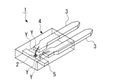
- FIG. 1 is a perspective view of a temperature sensor viewed from above, showing the inside of the temperature sensor according to a first embodiment of the present invention
- FIG. 2 is a perspective view showing a temperature sensor as viewed from below in the first embodiment.
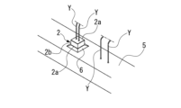
- FIG. 2 is an enlarged perspective view of a main part showing a heat-sensitive element mounted on a floating terminal in the first embodiment.
- 2 is a cross-sectional view taken along a floating terminal, illustrating a state in which a temperature sensor is embedded in a measurement object in the first embodiment.
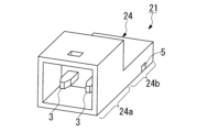
- FIG. FIG. 11 is a perspective view of a temperature sensor according to a second embodiment of the present invention, as viewed from the base end side.
- FIG. 11 is a perspective view of a temperature sensor according to a third embodiment of the present invention, seen from above and showing the inside of the temperature sensor.
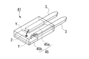
- FIG. 11 is a perspective view of a temperature sensor according to a fourth embodiment of the present invention, seen from above and showing the inside of the temperature sensor.
- FIG. 13 is a perspective view of a temperature sensor according to a fifth embodiment of the present invention, seen from above and showing the inside of the temperature sensor.
- 4 is a graph of a thermal time constant simulation showing temperature change over time for an embodiment of a temperature sensor according to the present invention.
- the temperature sensor 1 of this embodiment comprises a thermal element 2 having electrode surfaces 2a on the upper and lower surfaces, a pair of lead terminals 3 electrically connected to the thermal element 2, a resin sealing portion 4 in which the thermal element 2 and the tips of the pair of lead terminals 3 are sealed with resin, and a conductive floating terminal 5 that has at least one surface exposed and is embedded in the resin sealing portion 4 and spaced apart from the pair of lead terminals 3.
- the temperature sensor 1 of this embodiment is disposed so that at least the exposed lower surface of the floating terminal 5 is in contact with the coil conductor of a motor stator, for example, to detect the temperature of the coil conductor.
- the thermal element 2 is mounted on the floating terminal 5 with the electrode surface 2 a on the lower surface thereof bonded to the floating terminal 5 with a conductive adhesive 6 .
- the conductive bonding material 6 is, for example, solder.
- the electrical connection between the upper electrode surface 2 a and the other of the pair of lead terminals 3 , and the electrical connection between the floating terminal 5 and one of the pair of lead terminals 3 are made by bonding wires Y.
- the floating terminal 5 is exposed on the lower surface and side surfaces of the resin sealing portion 4 .
- the floating terminal 5 is disposed apart from the tips of the pair of lead terminals 3 and has a long plate or rectangular column shape extending in a direction perpendicular to the direction in which the pair of lead terminals 3 extend.
- the heat-sensitive element 2 is a flake-type thermistor having electrode surfaces 2a made of a layer of a conductive material such as metal formed on the upper and lower surfaces of a plate-shaped thermistor material portion 2b.
- the pair of lead terminals 3 are lead frames extending parallel to each other within the resin sealing portion 4 .
- the resin sealing portion 4 is formed from an insulating resin such as an epoxy resin, and is molded into a rectangular plate shape or a low-profile box shape in a plan view. The resin sealing portion 4 covers and seals the floating terminals 5, the heat sensitive element 2, the bonding wires Y and the tip ends of the pair of lead terminals 3.
- the floating terminal 5 is made of a conductive material with high thermal conductivity, such as copper.
- the floating terminal 5 is formed in a rod shape (long plate shape or square column shape) with a rectangular cross section, and both end faces as well as the lower face are exposed from the resin sealing portion 4 .
- the bottom surface of the floating terminal 5 is set to be flush with the bottom surface of the resin sealing portion 4.
- a thermal interface material (TIM) or a heat dissipation sheet may be attached to the bottom surfaces of the floating terminal 5 and the resin sealing portion 4, which are the contact surfaces with the measurement object, to absorb unevenness.
- the thermal element 2 is mounted on the floating terminal 5 with the lower electrode surface 2a adhered to the floating terminal 5 with conductive bonding material 6, so that the thermal element 2 is in direct contact with the floating terminal 5 which functions as a heat spreader, thereby achieving high thermal responsiveness.
- the electrical connection between the floating terminal 5 and one of the pair of lead terminals 3, and the electrical connection between the upper electrode surface 2a and the other of the pair of lead terminals 3 are made by bonding wire Y, so that the floating terminal 5 is thermally floating from the pair of lead terminals 3, and the heat received by the floating terminal 5 from the object to be measured is difficult to dissipate from the lead terminal 3.
- this temperature sensor 1 by placing the exposed surface of the thermally floating floating terminal 5, which functions as a heat spreader, in contact with the object to be measured, heat can be efficiently transferred to the thermal element 2 mounted on the floating terminal 5, making it possible to measure temperature with high thermal responsiveness.
- the floating terminal 5 since the floating terminal 5 is exposed on the underside and sides of the resin sealing portion 4, when the floating terminal 5 is embedded in the measurement object S as shown in Figure 4, the heat of the measurement object S can be received not only from the underside but also from the sides and transmitted to the thermal element 2, thereby improving the thermal responsiveness.
- the floating terminal 5 is disposed at a distance from the tips of the pair of lead terminals 3 and is a long plate or rectangular column extending in a direction perpendicular to the extension direction of the pair of lead terminals 3, the exposed area of the underside increases in the extension direction, making it suitable for installation on a measurement object extending along the extension direction of the floating terminal 5. Also, it becomes possible to separate the entire floating terminal 5 further from the lead terminals, further improving thermal response.
- the resin sealing portion 4 is simply plate-shaped, and the base ends of the pair of lead terminals 3 simply protrude from the base end surface, whereas in the temperature sensor 21 of the second embodiment, as shown in FIG. 5, the resin sealing portion 24 has a connector portion 24a into which a pair of external wires can be inserted to connect the base ends of the pair of lead terminals 3 to a pair of external wires.
- the resin sealing portion 24 of the second embodiment includes a tip side sealing portion 24b that seals the tip sides of the thermal element 2, the floating terminal 5 and the pair of lead terminals 3, and the connector portion 24a connected to the base end of the tip side sealing portion 24b.
- the connector portion 24a has a rectangular opening toward the base end, and allows the terminals of a pair of external wiring to be inserted therein. The base ends of a pair of lead terminals 3 protrude into the connector portion 24a.
- the resin sealing portion 24 has a connector portion 24a into which a pair of external wiring can be inserted to connect the base ends of the pair of lead terminals 3 to a pair of external wiring, so that the external wiring can be easily connected by the connector portion 24a.
- the difference between the third embodiment and the first embodiment is that in the first embodiment, the floating terminal 5 is disposed at a distance from the tips of the pair of lead terminals 3 and has a long plate or rectangular column shape extending in a direction perpendicular to the extension direction of the pair of lead terminals 3, whereas in the temperature sensor 31 of the third embodiment, the floating terminal 35 extends between the pair of lead terminals 3 as shown in FIG. 6.
- the floating terminal 35 in the third embodiment has a long plate shape or a rectangular column shape, and extends parallel to the lead terminals 3 between the pair of lead terminals 3 within the resin sealing portion 4 .
- the pair of lead terminals 3 extend to the vicinity of the tip of the resin sealing portion 4 .
- the floating terminal 35 extends between a pair of lead terminals 3, so that the exposed area of the underside increases in the extension direction, making it suitable for installation on a measurement object that extends along the extension direction of the lead terminals 3 (extension direction of the floating terminal 35).
- the floating terminal 35 is a long plate or a rectangular column extending between a pair of lead terminals 3, in the temperature sensor 41 of the fourth embodiment, as shown in FIG. 7, the floating terminal 45 is substantially T-shaped with a vertically long portion 45a extending between a pair of lead terminals 3 and a horizontally long portion 45b connected to the tip of the vertically long portion 45a and having a rectangular shape in plan view that is long in a direction perpendicular to the extension direction of the lead terminals 3.
- the horizontally elongated portion 45b is formed to be wider than the floating terminal 5 of the first embodiment.
- the floating terminal 45 is approximately T-shaped with a vertically elongated portion 45a and a horizontally elongated portion 45b, so that the exposed area of the lower surface is increased, thereby achieving higher thermal responsiveness.
- the difference between the fifth embodiment and the first embodiment is that in the first embodiment, the floating terminal 5 is in the shape of a long plate or a rectangular column extending in a direction perpendicular to the extension direction of the lead terminal 3, whereas in the temperature sensor 51 of the fifth embodiment, as shown in FIG. 7, the floating terminal 55 is in the shape of a rectangular plate in plan view that is long in the extension direction of the lead terminal 3.
- the pair of lead terminals 53 are shorter than those in the first embodiment, and the floating terminals 55 are accordingly flat and expanded in the extending direction of the lead terminals 3 .
- the floating terminal 55 is flat and extends in the extension direction of the lead terminal 3, so that the exposed area of the bottom and side surfaces is increased, thereby achieving better thermal responsiveness.
- the simulation was performed with the environmental temperature set to 25° C. and the thermal conductivity of the heat dissipation sheet set to 2 W/mK.
- the thermal time constant is the time it takes for the temperature of the thermal element to reach 104°C when the temperature of the winding is 150°C.
- the temperature sensor of the present invention has a high thermal response with a thermal time constant of 0.7 sec, and is capable of measuring the temperature of the windings quickly.
- a thermistor is used, but the thermistor may be a chip thermistor, a flake type thermistor, a thin film thermistor, or the like, or a pyroelectric element may also be used.
- the thermistor it is preferable for the thermistor to be a heat-sensitive element capable of withstanding heat up to 200°C.
Landscapes
- Physics & Mathematics (AREA)
- General Physics & Mathematics (AREA)
- Nonlinear Science (AREA)
- Measuring Temperature Or Quantity Of Heat (AREA)
Abstract
Description
このような測定対象物に接触状態に設置する温度センサとしては、絶縁性基板にフレーク型サーミスタを実装したものが知られている。
さらに、特許文献3にも、絶縁性基板の一面に感熱膜と電極とを形成すると共に絶縁性基板の他面に金属等の集熱膜を形成した感熱素子を備えた温度センサが記載されている。
すなわち、モータステータのコイル導線等の高温になる測定対象物の温度を検出するための温度センサでは、モータの熱に素早く反応して制御するために、さらに高い熱応答性や熱追従性が求められている。しかしながら、従来の技術では、測定対象物に接触する面に金属等の集熱膜を形成することで、効率的に熱を伝えて熱応答性を向上させているが、集熱膜と感熱素子との間に絶縁性基板等が介在するため、さらに高い熱応答性や熱追従性を得ることが困難であった。
また、フローティング端子と一対のリード端子の一方との電気的接続、及び上面の電極面と一対のリード端子の他方との電気的接続が、ボンディングワイヤで行われているので、フローティング端子が一対のリード端子から熱的に浮いた状態となり、測定対象物からフローティング端子が受けた熱が、リード端子から放熱され難くなる。
したがって、この温度センサでは、ヒートスプレッダとして機能し熱的に浮いたフローティング端子の露出面を測定対象物に接触させた状態で設置することで、フローティング端子上に実装された感熱素子に効率的に伝熱させることができ、高い熱応答性を有して温度を計測することが可能になる。
すなわち、この温度センサでは、フローティング端子が、樹脂封止部の下面と側面とに露出しているので、測定対象物に埋め込んで設置される場合に、下面だけでなく側面からも測定対象物の熱を受けて感熱素子に伝えることができ、より熱応答性を高めることができる。
すなわち、この温度センサでは、フローティング端子が、一対のリード端子の先端から離間して配置されていると共に、一対のリード端子の延在方向に対して直交する方向に延在した長板状又は角柱状であるので、下面の露出面積が延在方向に増大し、フローティング端子の延在方向に沿って延在する測定対象物に設置する場合等に適している。また、フローティング端子全体をよりリード端子から離間させることが可能になって、さらに熱応答性が向上する。
すなわち、この温度センサでは、樹脂封止部が、一対の外部配線を差し込むことで一対のリード端子の基端と一対の外部配線とが接続可能なコネクタ部を有しているので、コネクタ部によって外部配線を容易に接続することができる。
すなわち、この温度センサでは、フローティング端子が、一対のリード端子の間に延在しているので、下面の露出面積が延在方向に増大し、リード端子の延在方向(フローティング端子の延在方向)に沿って延在する測定対象物に設置する場合等に適している。
すなわち、本発明に係る温度センサによれば、感熱素子が、下面の電極面をフローティング端子に導電性接合材で接着させた状態でフローティング端子上に実装され、フローティング端子と一対のリード端子の一方との電気的接続、及び上面の電極面と一対のリード端子の他方との電気的接続が、ボンディングワイヤで行われているので、ヒートスプレッダとして機能し熱的に浮いたフローティング端子上に実装された感熱素子に効率的に伝熱させることができ、高い熱応答性を有して温度を計測することが可能になる。
このように本発明の温度センサでは、熱応答性が高速化するため、モータステータのコイル導線等の高精度な温度測定に好適である。
また、感熱素子2は、下面の電極面2aをフローティング端子5に導電性接合材6で接着させた状態でフローティング端子5上に実装されている。
上記導電性接合材6は、例えばハンダである。
上記フローティング端子5は、樹脂封止部4の下面と側面とに露出している。
また、フローティング端子5は、一対のリード端子3の先端から離間して配置されていると共に、一対のリード端子3の延在方向に対して直交する方向に延在した長板状又は角柱状である。
上記一対のリード端子3は、樹脂封止部4内で互いに平行に延在したリードフレームである。
上記樹脂封止部4は、例えばエポキシ樹脂等の絶縁性樹脂で形成され、平面視長方形の板状又は低背の箱状に成形されている。
なお、樹脂封止部4は、フローティング端子5,感熱素子2,ボンディングワイヤY及び一対のリード端子3の先端部側を覆って封止している。
上記フローティング端子5は、例えば銅等の高熱伝導率の導電性材料で形成されている。
また、フローティング端子5の下面は、樹脂封止部4の下面と、面一に設定されている。なお、測定対象物との接触面であるフローティング端子5の下面及び樹脂封止部4の下面に、TIM(Thermal Interface Material)材や放熱シートを付けて凹凸を吸収するようにしても構わない。
また、フローティング端子5と一対のリード端子3の一方との電気的接続、及び上面の電極面2aと一対のリード端子3の他方との電気的接続が、ボンディングワイヤYで行われているので、フローティング端子5が一対のリード端子3から熱的に浮いた状態となり、測定対象物からフローティング端子5が受けた熱が、リード端子3から放熱され難くなる。
また、フローティング端子5が、樹脂封止部4の下面と側面とに露出しているので、図4に示すように、測定対象物Sに埋め込んで設置される場合に、下面だけでなく側面からも測定対象物Sの熱を受けて感熱素子2に伝えることができ、より熱応答性を高めることができる。
上記コネクタ部24aは、基端側に向けて矩形状に開口しており、一対の外部配線の端子が挿入可能になっている。このコネクタ部24aの内部には、一対のリード端子3の基端部が突出している。
また、一対のリード端子3は、樹脂封止部4の先端近傍まで延在している。
このように第3実施形態の温度センサ31では、フローティング端子35が、一対のリード端子3の間に延在しているので、下面の露出面積が延在方向に増大し、リード端子3の延在方向(フローティング端子35の延在方向)に沿って延在する測定対象物に設置する場合等に適している。
このように第4実施形態の温度センサ41では、フローティング端子45が、縦長部分45aと横長部分45bとを備えた略T字状になっているので、下面の露出面積がより増大して、より高い熱応答性を得ることができる。
このように第5実施形態の温度センサ51では、フローティング端子55がリード端子3の延在方向に拡がった平板状になっているので、下面及び側面の露出面積が増大して、より熱応答性を得ることができる。
また、熱時定数は、巻き線の温度150℃のとき、感熱素子が104℃に達するまでの時間である。
この結果からわかるように、本発明の温度センサでは、熱時定数が0.7secと熱応答性が高く、素早く巻き線の温度を計測可能である。
Claims (5)
- 上面及び下面に電極面を有した感熱素子と、
前記感熱素子に電気的に接続された一対のリード端子と、
前記感熱素子及び前記一対のリード端子の先端部を樹脂で封止した樹脂封止部と、
少なくとも一面を露出させて前記樹脂封止部に埋め込まれ前記一対のリード端子から離間した導電性のフローティング端子とを備え、
前記感熱素子が、前記下面の電極面を前記フローティング端子に導電性接合材で接着させた状態で前記フローティング端子上に実装され、
前記フローティング端子と前記一対のリード端子の一方との電気的接続、及び前記上面の電極面と前記一対のリード端子の他方との電気的接続が、ボンディングワイヤで行われていることを特徴とする温度センサ。 - 請求項1に記載の温度センサにおいて、
前記フローティング端子が、前記樹脂封止部の下面と側面とに露出していることを特徴とする温度センサ。 - 請求項1又は2に記載の温度センサにおいて、
前記フローティング端子が、前記一対のリード端子の先端から離間して配置されていると共に、前記一対のリード端子の延在方向に対して直交する方向に延在した長板状又は角柱状であることを特徴とする温度センサ。 - 請求項1又は2に記載の温度センサにおいて、
前記樹脂封止部が、一対の外部配線を差し込むことで前記一対のリード端子の基端と前記一対の外部配線とが接続可能なコネクタ部を有していることを特徴とする温度センサ。 - 請求項1に記載の温度センサにおいて、
前記一対のリード端子が、前記樹脂封止部内で互いに平行に延在しており、
前記フローティング端子が、前記一対のリード端子の間に延在していることを特徴とする温度センサ。
Priority Applications (2)
| Application Number | Priority Date | Filing Date | Title |
|---|---|---|---|
| CN202380081099.XA CN120265959A (zh) | 2022-11-29 | 2023-11-28 | 温度传感器 |
| EP23897767.2A EP4628862A1 (en) | 2022-11-29 | 2023-11-28 | Temperature sensor |
Applications Claiming Priority (2)
| Application Number | Priority Date | Filing Date | Title |
|---|---|---|---|
| JP2022190087A JP2024077876A (ja) | 2022-11-29 | 2022-11-29 | 温度センサ |
| JP2022-190087 | 2022-11-29 |
Publications (1)
| Publication Number | Publication Date |
|---|---|
| WO2024117119A1 true WO2024117119A1 (ja) | 2024-06-06 |
Family
ID=91323825
Family Applications (1)
| Application Number | Title | Priority Date | Filing Date |
|---|---|---|---|
| PCT/JP2023/042525 Ceased WO2024117119A1 (ja) | 2022-11-29 | 2023-11-28 | 温度センサ |
Country Status (4)
| Country | Link |
|---|---|
| EP (1) | EP4628862A1 (ja) |
| JP (1) | JP2024077876A (ja) |
| CN (1) | CN120265959A (ja) |
| WO (1) | WO2024117119A1 (ja) |
Citations (8)
| Publication number | Priority date | Publication date | Assignee | Title |
|---|---|---|---|---|
| JPS53164188U (ja) * | 1977-05-30 | 1978-12-22 | ||
| JPH043325U (ja) | 1990-04-25 | 1992-01-13 | ||
| JPH09210802A (ja) * | 1996-02-02 | 1997-08-15 | Sharp Corp | 表面実装用温度検出素子 |
| JPH11304599A (ja) * | 1998-04-15 | 1999-11-05 | Mitsui Mining & Smelting Co Ltd | 温度センサー |
| JP2005134119A (ja) * | 2003-10-28 | 2005-05-26 | Matsushita Electric Works Ltd | 熱検知素子 |
| JP2006064497A (ja) | 2004-08-26 | 2006-03-09 | Mitsubishi Materials Corp | 薄型温度センサ及びその製造方法 |
| JP2016138773A (ja) | 2015-01-27 | 2016-08-04 | 三菱マテリアル株式会社 | 温度センサ |
| JP2017072401A (ja) * | 2015-10-05 | 2017-04-13 | 三菱マテリアル株式会社 | 温度センサ |
-
2022
- 2022-11-29 JP JP2022190087A patent/JP2024077876A/ja active Pending
-
2023
- 2023-11-28 CN CN202380081099.XA patent/CN120265959A/zh active Pending
- 2023-11-28 EP EP23897767.2A patent/EP4628862A1/en active Pending
- 2023-11-28 WO PCT/JP2023/042525 patent/WO2024117119A1/ja not_active Ceased
Patent Citations (8)
| Publication number | Priority date | Publication date | Assignee | Title |
|---|---|---|---|---|
| JPS53164188U (ja) * | 1977-05-30 | 1978-12-22 | ||
| JPH043325U (ja) | 1990-04-25 | 1992-01-13 | ||
| JPH09210802A (ja) * | 1996-02-02 | 1997-08-15 | Sharp Corp | 表面実装用温度検出素子 |
| JPH11304599A (ja) * | 1998-04-15 | 1999-11-05 | Mitsui Mining & Smelting Co Ltd | 温度センサー |
| JP2005134119A (ja) * | 2003-10-28 | 2005-05-26 | Matsushita Electric Works Ltd | 熱検知素子 |
| JP2006064497A (ja) | 2004-08-26 | 2006-03-09 | Mitsubishi Materials Corp | 薄型温度センサ及びその製造方法 |
| JP2016138773A (ja) | 2015-01-27 | 2016-08-04 | 三菱マテリアル株式会社 | 温度センサ |
| JP2017072401A (ja) * | 2015-10-05 | 2017-04-13 | 三菱マテリアル株式会社 | 温度センサ |
Non-Patent Citations (1)
| Title |
|---|
| See also references of EP4628862A1 |
Also Published As
| Publication number | Publication date |
|---|---|
| JP2024077876A (ja) | 2024-06-10 |
| CN120265959A (zh) | 2025-07-04 |
| EP4628862A1 (en) | 2025-10-08 |
Similar Documents
| Publication | Publication Date | Title |
|---|---|---|
| JP2011033479A (ja) | 温度センサ | |
| JP3725296B2 (ja) | 測定抵抗体を有する温度センサ | |
| MXPA97003843A (es) | Sensor de temperatura con resistor de medicion | |
| CN212963756U (zh) | 一种温度传感器、温度传感器组及测温装置 | |
| JP6880484B2 (ja) | 温度センサ | |
| JP6776605B2 (ja) | 温度センサの実装構造 | |
| CN212963757U (zh) | 一种温度传感元件、测温组件及电池包 | |
| WO2024117119A1 (ja) | 温度センサ | |
| WO2026036998A1 (zh) | 开关器件测温结构和车载充电机 | |
| JP2003303702A (ja) | 温度検出素子およびこれを備える回路基板 | |
| JP6507372B2 (ja) | 電気素子と温度検知器とを備えた電子装置 | |
| JP6880482B2 (ja) | 温度センサ | |
| JP2019174135A (ja) | 温度センサ | |
| JP2024131353A (ja) | 温度センサ | |
| JPH0476943A (ja) | 半導体素子 | |
| EP4354104B1 (en) | Electronic device and method for producing an electronic device | |
| JP7361981B1 (ja) | 温度センサおよび回転電機 | |
| US20250316550A1 (en) | Power module and method for producing a power module | |
| JP7345445B2 (ja) | 半導体装置 | |
| JPH04102365A (ja) | ダイオード | |
| JP7396138B2 (ja) | 温度センサ | |
| JPS62170359A (ja) | サ−マルヘツド | |
| JP7008189B2 (ja) | 温度センサ | |
| CN118016607A (zh) | 电子组件和用于制造电子组件的方法 | |
| JPS6312923A (ja) | 液面検出器 |
Legal Events
| Date | Code | Title | Description |
|---|---|---|---|
| 121 | Ep: the epo has been informed by wipo that ep was designated in this application |
Ref document number: 23897767 Country of ref document: EP Kind code of ref document: A1 |
|
| WWE | Wipo information: entry into national phase |
Ref document number: 202380081099.X Country of ref document: CN |
|
| WWE | Wipo information: entry into national phase |
Ref document number: 2023897767 Country of ref document: EP |
|
| NENP | Non-entry into the national phase |
Ref country code: DE |
|
| WWP | Wipo information: published in national office |
Ref document number: 202380081099.X Country of ref document: CN |
|
| ENP | Entry into the national phase |
Ref document number: 2023897767 Country of ref document: EP Effective date: 20250630 |
|
| WWP | Wipo information: published in national office |
Ref document number: 2023897767 Country of ref document: EP |