WO2024181581A1 - Système d'impression - Google Patents
Système d'impression Download PDFInfo
- Publication number
- WO2024181581A1 WO2024181581A1 PCT/JP2024/008161 JP2024008161W WO2024181581A1 WO 2024181581 A1 WO2024181581 A1 WO 2024181581A1 JP 2024008161 W JP2024008161 W JP 2024008161W WO 2024181581 A1 WO2024181581 A1 WO 2024181581A1
- Authority
- WO
- WIPO (PCT)
- Prior art keywords
- image
- card
- medium
- data
- unit
- Prior art date
- Legal status (The legal status is an assumption and is not a legal conclusion. Google has not performed a legal analysis and makes no representation as to the accuracy of the status listed.)
- Ceased
Links
Images






Classifications
-
- B—PERFORMING OPERATIONS; TRANSPORTING
- B41—PRINTING; LINING MACHINES; TYPEWRITERS; STAMPS
- B41J—TYPEWRITERS; SELECTIVE PRINTING MECHANISMS, i.e. MECHANISMS PRINTING OTHERWISE THAN FROM A FORME; CORRECTION OF TYPOGRAPHICAL ERRORS
- B41J2/00—Typewriters or selective printing mechanisms characterised by the printing or marking process for which they are designed
- B41J2/315—Typewriters or selective printing mechanisms characterised by the printing or marking process for which they are designed characterised by selective application of heat to a heat sensitive printing or impression-transfer material
- B41J2/32—Typewriters or selective printing mechanisms characterised by the printing or marking process for which they are designed characterised by selective application of heat to a heat sensitive printing or impression-transfer material using thermal heads
- B41J2/325—Typewriters or selective printing mechanisms characterised by the printing or marking process for which they are designed characterised by selective application of heat to a heat sensitive printing or impression-transfer material using thermal heads by selective transfer of ink from ink carrier, e.g. from ink ribbon or sheet
-
- B—PERFORMING OPERATIONS; TRANSPORTING
- B41—PRINTING; LINING MACHINES; TYPEWRITERS; STAMPS
- B41J—TYPEWRITERS; SELECTIVE PRINTING MECHANISMS, i.e. MECHANISMS PRINTING OTHERWISE THAN FROM A FORME; CORRECTION OF TYPOGRAPHICAL ERRORS
- B41J2/00—Typewriters or selective printing mechanisms characterised by the printing or marking process for which they are designed
- B41J2/485—Typewriters or selective printing mechanisms characterised by the printing or marking process for which they are designed characterised by the process of building-up characters or image elements applicable to two or more kinds of printing or marking processes
- B41J2/505—Typewriters or selective printing mechanisms characterised by the printing or marking process for which they are designed characterised by the process of building-up characters or image elements applicable to two or more kinds of printing or marking processes from an assembly of identical printing elements
-
- B—PERFORMING OPERATIONS; TRANSPORTING
- B41—PRINTING; LINING MACHINES; TYPEWRITERS; STAMPS
- B41J—TYPEWRITERS; SELECTIVE PRINTING MECHANISMS, i.e. MECHANISMS PRINTING OTHERWISE THAN FROM A FORME; CORRECTION OF TYPOGRAPHICAL ERRORS
- B41J3/00—Typewriters or selective printing or marking mechanisms characterised by the purpose for which they are constructed
- B41J3/407—Typewriters or selective printing or marking mechanisms characterised by the purpose for which they are constructed for marking on special material
-
- B—PERFORMING OPERATIONS; TRANSPORTING
- B41—PRINTING; LINING MACHINES; TYPEWRITERS; STAMPS
- B41J—TYPEWRITERS; SELECTIVE PRINTING MECHANISMS, i.e. MECHANISMS PRINTING OTHERWISE THAN FROM A FORME; CORRECTION OF TYPOGRAPHICAL ERRORS
- B41J3/00—Typewriters or selective printing or marking mechanisms characterised by the purpose for which they are constructed
- B41J3/60—Typewriters or selective printing or marking mechanisms characterised by the purpose for which they are constructed for printing on both faces of the printing material
-
- B—PERFORMING OPERATIONS; TRANSPORTING
- B41—PRINTING; LINING MACHINES; TYPEWRITERS; STAMPS
- B41J—TYPEWRITERS; SELECTIVE PRINTING MECHANISMS, i.e. MECHANISMS PRINTING OTHERWISE THAN FROM A FORME; CORRECTION OF TYPOGRAPHICAL ERRORS
- B41J5/00—Devices or arrangements for controlling character selection
- B41J5/30—Character or syllable selection controlled by recorded information
-
- G—PHYSICS
- G06—COMPUTING OR CALCULATING; COUNTING
- G06F—ELECTRIC DIGITAL DATA PROCESSING
- G06F3/00—Input arrangements for transferring data to be processed into a form capable of being handled by the computer; Output arrangements for transferring data from processing unit to output unit, e.g. interface arrangements
- G06F3/12—Digital output to print unit, e.g. line printer, chain printer
Definitions
- the present invention relates to a printing system that forms images on a transparent medium.
- Card printers that form images on card-shaped media (hereafter referred to as cards) are known from the past. Typically, such card printers form an image on the card surface so that it is visible to the user when the user looks at the side of the card that faces the user (card front surface).
- the present invention aims to provide a printing system that can meet the needs of each user.
- the printing system of the present invention is a printing system that forms an image on a transparent medium, and is characterized by comprising an image data input unit to which image data is input, a selection information input unit to which selection information for creating a first printed matter in which the user views the image against the background of the medium or a second printed matter in which the user views the image through the medium, a print data generation unit that, when creating the first printed matter, generates first print data from the image data so that the image formed on the medium has the same orientation as the image data when viewed, and, when creating the second printed matter, generates second print data from the image data so that the image is a mirror image of the first print data, and an image formation unit that forms an image on the medium based on the print data generated by the print data generation unit.
- the present invention provides a printing system that can meet the needs of both users who want to view an image formed on the user side with a transparent medium as the background, and users who want to view an image through a transparent medium.
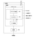
- FIG. 1 is a configuration block diagram of a control and communication system of a printing system according to a first embodiment to which the present invention can be applied;
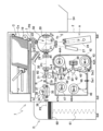
- FIG. 1 is a front view showing a schematic configuration of a printing device that constitutes a printing system.
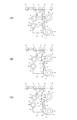
- 1A is an explanatory diagram of the operating positions of the printing unit of a printing device, in which (A) shows the printing unit in a standby position, (B) shows the printing unit in a printing position, and (C) shows the printing unit in a transport position.
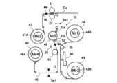
- FIG. 4 is a front view of the printing device during transfer.
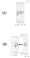
- FIG. 2 is a cross-sectional view of a transfer film.
- FIG. 2 is a front view of the transfer film.
- 13 is a diagram showing a state in which an image is formed on a first card Ca1.
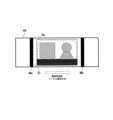
- FIG. 1 is a diagram for explaining in what direction an image formed on a transparent medium is viewed.
- the printing system 100 of this embodiment is composed of a printing device 1 that prints and records characters and images on a card-shaped medium (hereinafter, card Ca) and records information magnetically or electrically on the card, and a higher-level device 101 (e.g., a host computer such as a personal computer) that can communicate with the printing device 1.
- a printing device 1 that prints and records characters and images on a card-shaped medium (hereinafter, card Ca) and records information magnetically or electrically on the card
- a higher-level device 101 e.g., a host computer such as a personal computer
- the printing device 1 is connected to a host device 101, and the host device 101 can send print data and magnetic or electrical recording data to the printing device 1 to instruct recording operations.
- the printing device 1 has an operation panel (operation display unit) 5, and in addition to recording operation instructions from the host device 101, recording operation instructions can also be received from the operation panel 5.
- the printing system 100 may also be configured as a so-called stand-alone type printing system 100 in which both the host device 101 and the printing device 1 are housed in the same housing.
- a retransfer printer that forms an image on a transfer film using an ink ribbon and transfers the image formed on the transfer film to a card Ca will be described.
- the upper level device 101 includes, as its hardware configuration, a CPU, a ROM, a RAM, a hard disk drive (hereinafter abbreviated as HDD), and a communication unit 155 (see FIG. 7) including a communication interface.
- a CPU central processing unit
- ROM read-only memory
- RAM random access memory
- HDD hard disk drive
- the host device 101 is connected to an image input device 104 such as a digital camera or scanner, an input device 103 such as a keyboard, mouse, or touch panel for inputting commands and data to the host device 101, and a monitor 102 such as a liquid crystal display for displaying data generated by the host device 101 (if the input device 103 is a touch panel, the input device and the monitor are common members).
- the image input device 104 may also be provided with a network connection unit for connecting to a network such as the Internet and downloading image data and text data to be printed.
- a reading device 105 may also be provided for reading two-dimensional codes such as QR codes (registered trademark) and information stored in IC chips via wireless communication, and printing data and setting information (such as the type of medium described below and information on whether to create a first or second printed matter) may be downloaded from an external server or read from a built-in memory based on the read information.
- QR codes registered trademark
- printing data and setting information such as the type of medium described below and information on whether to create a first or second printed matter
- Printing device 1 2 the printing device 1 has a housing 2, which includes an information recording unit A, a printing unit B, a rotating unit F, and a decurl mechanism G.
- the printing device 1 also includes a medium supply unit C that can be attached to the housing 2, a medium storage unit D, and a reject stacker 54 that is attached to the side of the housing 2 opposite the medium storage unit D.
- the information recording section A is composed of a magnetic recording section 24, a non-contact IC recording section 23, and a contact IC recording section 27. These three recording sections are optional, and one or more recording sections may be installed according to the user's desire.
- the medium supply unit C stores a number of cards Ca aligned in an upright (inclined) position.
- a separation opening 7 is formed at the bottom of the leading end, and a pickup roller 19 sequentially delivers and supplies the cards Ca in the front row.
- a standard (regular) size card with a width of 85.6 mm and a length of 53.9 mm is used as the card Ca, but it may be possible to accommodate cards of non-standard sizes, in which case it goes without saying that the dimensions of each component are determined according to the card size to be handled.
- the pickup roller 19 rotates by the driving force of a pickup motor (stepping motor) not shown.
- the printing system 100 of this embodiment is capable of printing on a non-transparent first card Ca1 (e.g., a plain white PVC card) and a transparent second card Ca2 (e.g., an acrylic card that is a plate of transparent acrylic material), and the first card Ca1 and the second card Ca2 are collectively referred to as card Ca.
- the second card C2 does not need to be completely transparent, and is considered to be transparent as long as the image formed on the side opposite the surface facing the user can be viewed.
- both the first card Ca1 and the second card Ca2 may be colored.
- Rotating unit F A blank card Ca fed from the medium supply unit C is carried into the rotating unit F by a carry-in roller 22 arranged on the inclined medium transport path P0.
- the rotating unit F is composed of a rotating frame 50 rotatably supported on the housing 2, and two roller pairs 20, 21 rotatably supported on the rotating frame 50.
- the carry-in roller 22 and the roller pairs 20, 21 are rotated by the driving force of a first card transport motor (a stepping motor capable of forward and reverse rotation) not shown, and the rotating unit F is rotated by the driving force of a rotating motor (a stepping motor capable of forward and reverse rotation) not shown.
- a gear is formed on the outer periphery of the rotating frame 50, and is engaged with a gear fitted to the motor shaft of the rotating motor.
- the above-mentioned magnetic recording unit 24, non-contact IC recording unit 23, and contact IC recording unit 27 are arranged on the outer periphery of the rotating unit F.
- the roller pairs 20 and 21 form a medium transport path 65 for transporting the card Ca toward one of these recording units 23, 24, and 27, and data is written magnetically or electrically to the card Ca in these recording units.
- a temperature sensor Th such as a thermistor for detecting the environmental temperature (outside air temperature) is arranged near the rotating unit F, and temperature correction is performed on the heating elements of the thermal head, heat roller, etc. (described later) provided in the printing unit B based on the environmental temperature detected by this temperature sensor Th.
- the printing unit B is composed of an image forming unit B1 that forms an image on a transfer film 47 by overlapping each color ink image of the ink ribbon 41 with a thermal head 40, and a transfer unit B2 that transfers the image formed on the transfer film 46 to a card Ca that is transported on a horizontal medium transport path P1 by a heat roller 33.
- the printing unit B has a film transport mechanism 10 that transports the transfer film 46 (in the image forming area) across the image forming unit B1 and the transfer unit B2.
- the printing unit B also has a horizontal media transport path P1 for transporting the card Ca on an extension of the media transport path 65.
- a pair of transport rollers 29, 30 are arranged on the horizontal media transport path P1 to transport the card Ca towards the transfer unit B2.
- a horizontal medium transport path P2 is provided on an extension of the horizontal medium transport path P1 for transporting the card Ca after transfer to the storage stacker 60.
- Transport roller pairs 37 and 38 for transporting the card Ca are arranged on the horizontal medium transport path P2.
- Each roller (including the platen roller 31) from the transport roller pair 29 to the transport roller pair 38 arranged on the horizontal medium transport paths P1 and P2 rotates by the driving force of a second card transport motor (a stepping motor capable of forward and reverse rotation) (not shown).
- the pair of transport rollers 37, 38 constitute a part of the decurl mechanism G.
- the decurl mechanism G corrects the warp caused in the card Ca by the thermal transfer by the heat roller 33 by sandwiching the card Ca between the pair of transport rollers 37, 38 and the concave decurl unit 35, which is fixed in position by pressing the central portion of the card Ca, both ends of which are nipped, downward with the convex decurl unit 34.
- the decurl mechanism G is configured to include an eccentric cam 36, which allows the decurl unit 34 to move forward and backward in the vertical direction shown in FIG. 2.
- the media storage section D has a storage stacker 60 having a card loading platform for storing cards Ca transported from the decurling mechanism G side, and a lifting mechanism 61 configured to move downward in Figure 2 according to the number of cards Ca stacked on the card loading platform.
- Printing Unit B Next, the printing unit B will be described in detail in the order of image forming unit B1, transfer unit B2, the operation position of printing unit B, the image formation start position, and the transfer start position.
- the platen roller 45 and the thermal head 40 are main components that constitute the image forming section B1, and the thermal head 40 is disposed at a position facing the platen roller 45. At this time, the platen roller 45 is pressed against the thermal head 40 via the transfer film 46 and the ink ribbon 41. That is, the platen roller 45 is configured to be able to advance and retreat with respect to the thermal head 40 by rotating a first eccentric cam (not shown). It has been done.
- the thermal head 40 has multiple heating elements (1,300 in this example) arranged in a row in the main scanning direction, and these heating elements are selectively heated and controlled based on print data by a head control IC (not shown), forming an image on the transfer film 46 via the ink ribbon 41.
- a head control IC not shown
- the transfer film 46 is in the form of a band having a width slightly larger than the width direction of the card Ca, and as shown in Fig. 5(A), the ink receiving layer 46a that receives the ink of the ink ribbon 41, the protective layer 46b that protects the surface of the ink receiving layer 46a, the peeling layer 46c that promotes peeling of the ink receiving layer 46a and the protective layer 46b together by heating, and the substrate (base film) 46d are laminated in this order (Fig. 5(A) is a cross-sectional image of the transfer film 46 seen from the thickness direction).
- the transfer film 46 and the card Ca are overlapped, and heat is applied from the substrate 46d side using the heat roller 33 to press them together, so that the ink receiving layer 46a and the protective layer 46b on which the image is formed are separated from the peeling layer 46c and transferred to the card Ca (see Fig. 5(B)).
- marks for determining the start position of image formation are formed at regular intervals on the transfer film 46 so as to cross the width direction (main scanning direction of the thermal head 40) which intersects with the film transport direction (sub-scanning direction of the thermal head 40) during image formation as indicated by the arrow, and the area between these marks is defined as the image formation area Ri.
- the image formation area Ri is defined by the mark Ma on the upstream side and the mark Mb on the downstream side in the film transport direction during image formation.
- the rectangular area indicated by the solid line within the image forming area Ri is the printing area Rp of the thermal head 40, and the area indicated by the two-dot chain line is the size of the card Ca.
- the printing area Rp of the thermal head 40 has a margin of about 0.5 mm in each of the top, bottom, left and right directions relative to the card Ca (larger than the size of the card Ca).
- the transfer film 46 is wound or unwound onto the supply roll 47 and take-up roll 48 in the transfer film cassette by the drive of the motors Mr2 and Mr4. That is, in the transfer film cassette, a supply spool 47A is disposed at the center of the supply roll 47, and a take-up spool 48A is disposed at the center of the take-up roll 48.
- the rotational driving force of the motor Mr2 is transmitted to the supply spool 47A via a gear not shown
- the rotational driving force of the motor Mr4 is transmitted to the take-up spool 48A via a gear not shown.
- the motors Mr2 and Mr4 are DC motors that can rotate forward and backward.
- the motor shafts of the motors Mr2 and Mr4 are provided with encoders (not shown) on the opposite side of the output shaft to detect the rotation speed of these motors.
- the transfer film 46 before the transfer process is wound around the supply spool 47A, and the used transfer film 46 (the portion that has been transferred in the transfer section B2) is wound around the take-up spool 48A. Therefore, when performing the image formation process (also called the primary transfer process) and the transfer process (also called the secondary transfer process) on the transfer film 46, the transfer film 46 is once unwound from the supply spool 47A to the take-up spool 48A side, and the image formation process and the transfer process are performed while the transfer film 46 is being taken up by the supply spool 47A.
- the image formation process also called the primary transfer process
- the transfer process also called the secondary transfer process
- the film transport roller 49 is the main drive roller for transporting the transfer film 46, and the transport amount and transport stop position of the transfer film 46 are determined by controlling the drive of this film transport roller 49.
- the film transport roller 49 is connected to a film transport motor Mr5 (stepping motor) that can rotate forward and backward.
- Mr5 stepping motor
- the motors Mr2 and Mr4 are also driven, but they play an auxiliary role in film transport, as they wind up the transfer film 46 unwound from either the supply roll 47 or the winding roll 48 on the other roll and apply tension to the transported transfer film 46.
- An encoder (not shown) is provided on the roller shaft of the film transport roller 49.
- Pinch roller 32a and pinch roller 32b are arranged on the circumferential surface of film transport roller 49.
- a tension receiving member 52 is provided to prevent transfer film 46 from moving away from film transport roller 49 due to the tension of transfer film 46 that is generated when pinch rollers 32a and 32b press transfer film 46 against film transport roller 49.
- the pinch rollers 32a and 32b are configured to be able to advance and retreat relative to the film transport roller 49 by rotating a second eccentric cam (not shown), and the tension receiving member 52 is also configured to be able to advance and retreat relative to the transfer film 46 by rotating the second cam.
- the roller shafts of the pinch rollers 32a and 32b and both ends of the tension receiving member 52 are supported by support members (not shown) to which rollers that abut against the second eccentric cams are fixed.
- Figure 2 shows the state in which the pinch rollers 32a and 32b advance toward the film transport roller 49, the transfer film 46 is wound around the film transport roller 49, and the tension receiving member 52 is in contact with the transfer film 46. As a result, the transfer film 46 is transported accurately a distance according to the number of rotations of the film transport roller 49.
- the film transport mechanism 10 therefore drives the film transport roller 49 disposed between the image forming section B1 and the transfer section B2 to transport the transfer film 46 forward and backward between the supply roll 47, the image forming section B1, the transfer section B2, and the take-up roll 48, and has the function of positioning the image forming area Ri of the transfer film 46 at the appropriate position in the image forming section B1 and the transfer section B2.
- a sensor Se1 having a light-emitting element and a light-receiving element is disposed between the take-up roll 48 and the image forming section B1 (thermal head 40, platen roller 45) to detect the marks formed on the transfer film 46 described above.
- a cooling fan 39 for cooling the thermal head 40 is disposed near the thermal head 40.
- the ink ribbon 41 is stored in an ink ribbon cassette 42, and is stored in a state of being stretched between a supply roll 43 that supplies the ink ribbon 41 to the ink cassette 42 and a take-up roll 44 that takes up the ink ribbon 41.
- a take-up spool 44A is disposed at the center of the take-up roll 44, and a supply spool 43A is disposed at the center of the supply roll 43.
- the take-up spool 44A rotates by the driving force of a motor Mr1, and the supply spool 43A rotates by the driving force of a motor Mr3.
- a DC motor capable of forward and reverse rotation is used for the motors Mr1 and Mr3.
- An encoder (not shown) that detects the rotation speed of each of these motors is provided on the motor shafts of the motors Mr1 and Mr3 at a position opposite to the output shaft side.
- the ink ribbon 41 is composed of Y (yellow), M (magenta), and C (cyan) color ink panels and a Bk (black) ink panel repeated in face sequence in the longitudinal direction.
- sublimation inks are used for the Y, M, and C color ink panels
- melt ink is used for the Bk ink panel.
- ink panels of other colors such as white, gold, silver, and fluorescent orange may also be arranged.
- a sensor Se2 is placed between the supply roll 43 and the image forming section B1 (thermal head 40, platen roller 45) to detect the position of the ink ribbon 41 by blocking the light from the light emitting element side to the light receiving element side by the Bk ink panel, and to position the ink ribbon 41 to the image forming section B1.
- roller shaft of the platen roller 45 and both ends of the peeling roller 25 are supported by support members (not shown) to which rollers that abut against the above-mentioned first eccentric cam are fixed, and when the first cam rotates, the pressure contact of the platen roller 45 against the thermal head 40 is released, and at the same time, the abutment of the peeling roller 25 against the peeling member 28 is also released.
- a sensor Se3 is disposed downstream of the film transport roller 49 to detect a mark formed on the transfer film 46.
- the card Ca which is held between the transport roller pair 29, 30 on the horizontal media transport path P1 and is stopped (on standby), begins to be transported toward the transfer section B2, and the image formation area Ri (print area Rp) of the transfer film 46 and the card Ca reach the transfer section B2 at the same time.
- an integrated transparent sensor is used for the sensor Se3.
- Transfer section B2 In the transfer section B2, the transfer film 46 is sandwiched together with the card Ca between the heat roller 33 and the platen roller 31, and the image formed in the image forming area Ri of the transfer film 46 is transferred to the card Ca. That is, during transfer, the heat roller 33 is pressed against the platen roller 31 via the card Ca and the transfer film 46 (the image forming area Ri), and the card Ca and the transfer film 46 are transported at the same speed and in the same direction.
- the heat roller 33 is attached to a lifting mechanism (not shown) so as to be pressed against and separated from the platen roller 31 via the transfer film 46.
- the transfer film 46 is separated (peeled) from the card Ca by a peeling pin 79 arranged between the heat roller 33 and the driven roller (the lower roller in Figure 2) that constitutes the transport roller pair 37, and is transported to the supply roll 47 side. Meanwhile, the card Ca with the image transferred to it is transported downstream on the horizontal media transport path P2 toward the decurling mechanism G (see also Figure 4).
- the printing unit B takes one of three positions, a standby position, a printing position, and a transport position, by controlling the rotation of the first and second eccentric cams described above.
- 3A shows the state in which the printing unit B is in the standby position.
- the pinch rollers 32a and 32b are not in pressure contact with the film transport roller 49, and the tension receiving member 52 is not in contact with the film transport roller 49.
- the platen roller 45 is not in pressure contact with the thermal head 40, and the peeling roller 25 is not in contact with the peeling member 28.
- 3B shows the state when the printing unit B has moved to the printing position. At that time, first, the pinch rollers 32a and 32b wind the transfer film 46 around the film transport roller 49, and the tension receiving member 52 comes into contact with the transfer film 46, and then the platen roller 45 presses against the thermal head 40. In this printing position, the platen roller 45 moves toward the thermal head 40 to sandwich the transfer film 46 and the ink ribbon 41.
- the transfer film 46 is transported by the rotation of the film transport roller 49, and at the same time, the ink ribbon 41 is taken up by the take-up roll 44 by the operation of the motor Mr1 and transported in the same direction.
- the transfer film 46 passes the sensor Se1 and the transfer film 46 reaches the image formation start position (described later), an image is formed by the thermal head 40 in the image formation area Ri of the transfer film 46.
- the transport amount of the transfer film 46 (the distance in the transport direction of the transfer film 46) is detected by an encoder provided on the film transport roller 49, and the rotation of the film transport roller 49 stops accordingly, and at the same time, the winding by the winding roll 44 due to the operation of the motor Mr1 also stops. This completes the image formation by the ink of the first ink panel (e.g., Y) on the image formation area Ri of the transfer film 46.
- the ink of the first ink panel e.g., Y
- FIG. 3(C) shows the state in which the printing unit B has moved to the transport position. In this state, the pinch rollers 32a and 32b still wrap the transfer film 46 around the film transport roller 49, and the tension receiving member 52 is still in contact with the transfer film 46.
- the transfer film 46 is transported backward to the initial position (cuing position) by the reverse rotation of the film transport roller 49.
- the amount of movement of the transfer film 46 is controlled by the rotation of the film transport roller 49, but the film is transported backward a predetermined length, which is equal to or greater than the length in the transport direction of the image forming area Ri where an image is formed with one color ink panel (for example, Y), and returned to the initial position so that the mark exceeds the detection position of the sensor Se1.
- the ink ribbon 41 is also rewound a predetermined amount by the motor Mr3, and the ink panel of the ink for the next image is brought to standby in the initial position (cuing position).
- the printer 1 is equipped with a control unit 70 that controls the overall operation of the printer 1.
- the control unit 70 has a microcomputer unit 72 (hereinafter abbreviated as MCU 72) that controls the printer 1.
- MCU 72 is composed of a CPU that operates at a high speed clock as a central processing unit, a ROM that stores the programs and program data of the printer 1, a RAM that acts as a work area for the CPU, and an internal bus that connects these.
- An external bus is connected to the MCU 72.
- a communication unit 71 having a communication IC and communicating with the higher-level device 101, and a memory 77 for temporarily storing print data to be used to form an image on the card Ca, and recording data to be magnetically or electrically recorded on the magnetic stripe or storage IC of the card Ca, etc. are connected.
- a signal processing unit 73 that processes signals from the above-mentioned sensors and encoders
- an actuator control unit 74 that includes a motor driver that supplies drive pulses and drive power to each motor
- a thermal head control unit 75 that has the above-mentioned head control IC and controls the thermal energy of the heating elements that make up the thermal head 40
- an operation display control unit 76 that controls the operation panel unit 5, the above-mentioned information recording unit A
- a buzzer activation circuit 78 that activates the buzzer 6 in the event of a transport error due to multiple feeding of cards Ca or a recording failure by the information recording unit A.
- the printing system 100 of this embodiment is configured to be able to perform printing on the second card Ca2 (transparent medium) in addition to the first card Ca1 (white card).
- the first side Ca2A of the second card Ca2 is the side facing the user when the user looks at the second card Ca2, and the second side Ca2B is the side opposite the first side Ca2A.
- the image is formed on the front side of the user with the card Ca as the background, similar to the first card Ca1. Therefore, the image can be viewed directly (through the protective layer) without going through the second card Ca2, so the user can see the image itself clearly.
- the second side Ca2B of the second card Ca2 the user can enjoy viewing the image in three dimensions through the second card Ca2.
- images can be formed on both sides of the second card Ca2, not just one side.
- images can be formed on both sides of the second card Ca2, not just one side.
- images can be formed on both sides of the second card Ca2, not just one side.
- FIG. 7C shows a mirror image of the image data ID formed on the transfer film 46 (symbol MI), and the transfer film 46 viewed from the ink receiving layer 46a side.
- the image MI formed on the ink receiving layer 46d is formed so that it has a mirror image relationship with the image data ID when the original image data ID is taken as a normal image.
- a conversion process may be performed to mirror-invert the image data ID, or a new image may be generated based on the image data ID as a mirror image. This allows the user to view the image MI formed through the protective layer 46b as an image (normal image) with the same orientation as the image data ID.
- the same process as the printing process for the first card Ca1 is performed, so that an image MI that is a mirror image of the image data ID is formed on the transfer film 46, and the ink receiving layer and protective layer of the transfer film 46 on which the image has been formed are transferred to the first side Ca2A of the second card Ca2 by the transfer unit B2.
- This allows the user to view the image MI formed on the first side Ca2A in the same orientation as the image data ID when the first side Ca2A of the second card Ca2 is faced toward the user.
- the printing system 100 of this embodiment when outputting a product in which the image formed on the second surface Ca2B of the second card Ca2 is to be viewed by the user through the second card Ca2, when forming an image on the transfer film 46 in the image forming unit B1, the image data ID (FIG. 8(A)) is not converted into a mirror image, but is formed as a normal image on the transfer film 46 (reference symbol NI in FIG.
- the orientation of the image to be printed can be changed depending on whether the user wishes to print on the first card Ca1 or the second card Ca2, and also, for the second card Ca2, whether the image is printed on the first side Ca2A so that the image can be viewed directly without going through the second card Ca2, or on the second side Ca2B so that the image can be viewed through the second card Ca2, thereby allowing the creation of printed material suited to the purpose.
- the upper device 101 converts the image data ID into print data for each color component. At that time, depending on the type of medium to which the image is ultimately transferred and information on which side of the medium the user views the image from, it is determined whether the image data is converted into print data as a mirror image or converted into print data as a normal image when converted into print data, and the converted print data is sent to the printing device 1. Meanwhile, on the printing device 1 side, an image is formed in the image formation area Ri by the thermal head 40 according to the received print data and adjustment values.
- the CPU, ROM, RAM, and HDD of the host device 101 function as a control unit 150. That is, the control unit 150 functions mainly with the CPU in accordance with the program (and program data) stored in the ROM and loaded in the RAM.
- the HDD of the control unit 150 is installed with object generation application software for generating the desired image data ID (image object) to be printed on the card Ca, a printer driver (application software) for generating print data for the printing device 1 from the image data ID generated by the object generation application software or the image data ID input from the outside via the input device 103, and the like.
- These application software programs may be installed on the HDD via a recording medium that can be read by the higher-level device 101, such as a CD-ROM, a floppy disk (FD), a USB memory, a ZIP, or an MO, or, if the higher-level device 101 is part of a network, the programs may be obtained from another computer via the communication unit 155 and installed on the HDD.
- a recording medium that can be read by the higher-level device 101, such as a CD-ROM, a floppy disk (FD), a USB memory, a ZIP, or an MO, or, if the higher-level device 101 is part of a network, the programs may be obtained from another computer via the communication unit 155 and installed on the HDD.
- the CPU constituting the control unit 150 simultaneously or selectively expands the object generation application software and printer driver installed on the HDD into the RAM as application 151, thereby realizing the functions of the object generation unit 152 and printer driver 153.
- the HDD also functions as a data storage unit 154 that stores data being created (processed) or already created (processed) by the object generation unit 152 and printer driver 153.
- the object generation unit 152 has an individual object generation unit that generates individual print objects, an object integration unit that integrates a plurality of objects, an image data generation unit that generates image data from an integrated object, and a GDI (Graphics Device Interface, see JP-A-2004-194041) that outputs image data ID and the like to the printer driver 153.
- GDI Graphics Device Interface
- Each of these units except for the GDI has a GUI (Graphics User Interface) function for controlling input/output with the monitor 102, input device 103, and image input device 104 by utilizing functions provided by the OS (Operating System).
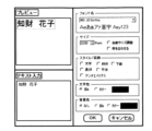
- FIG. 10 is a schematic diagram showing an example of a screen displayed on the monitor 102 when creating a print object of the owner's name "Intellectual Property Hanako" to be printed on the card Ca.
- the operator inputs "Intellectual Property Hanako" (text data) into the "Text Input” field from the keyboard of the input device 103, and inputs print information such as font name, font size, style/decoration, character color, background color, etc., with the mouse (not shown) of the input device 103, and the print object generated from the input text data and print information is displayed in the preview field.
- the operator While referring to the preview, the operator operates (modifies) the input device 103 to create the desired print object (text data), and clicks the OK button.
- This causes the individual object generation unit to import one print object (including the object's size information), assign a name and number to identify the print object, and store the print object in a predetermined folder.
- the print object displayed in the "Preview" column is made up of multiple characters, and a print object with the same font and font size is shown for these characters, but the print object may be made up of a single character, or may be made up of multiple characters, with each character using a different font and font size.
- card Ca is generally composed of various print objects (text data) such as the owner's name, the company name to which the owner belongs, and an ID number
- the individual object generation unit can generate other print objects (other than the name) following the above example, and store the generated print objects in the above-mentioned folder. Note that since the company name is common, a print object stored in another folder may be copied and stored in the above-mentioned folder.
- card Ca is generally also often printed with image objects such as the owner's face photo, the company logo, and a background image of the card, and these image objects may also be stored in the above-mentioned folder, or may be stored in another folder. Such image objects may be imported from image input device 104, or image objects stored in another computer may be used via communication unit 155.
- image objects such as the owner's face photo, the company logo, and a background image of the card, and these image objects may also be stored in the above-mentioned folder, or may be stored in another folder.
- image objects may be imported from image input device 104, or image objects stored in another computer may be used via communication unit 155.
- the operator creates a desired image object to be printed on the card Ca from the multiple objects contained in the folders described above.
- the object integration unit displays a preview image of the entire image on the monitor 102, and assists the operator in arranging the multiple objects. This allows the operator to obtain an integrated object in which the owner's name, company name, ID number, face photo, logo mark, etc. are arranged in the desired positions.
- the object integration unit determines whether the OK button on the preview image has been clicked, and if so, it assumes that the arrangement of the image (integrated) object to be printed on card Ca has been finalized, and obtains the position information of each object that makes up the integrated object. Therefore, the object integration unit has the function of adding position information for each object. Note that, although in this embodiment the position information for each object is stored in the folder described above, it may be stored in another folder.
- the image data generation unit converts each print object of the text data into an image data ID, such as a bitmap, and generates an image data ID that integrates all image data for each side of the card Ca into one.
- the image data generation unit also prompts the operator to select whether the generated image data ID will be used for double-sided or single-sided printing, and whether it will be used on the front or back side of card Ca, and acquires the results as attribute information of the image data. Furthermore, the image data generation unit requests the operator to input data to be recorded on the magnetic stripe or IC of card Ca and to identify the recording unit (23, 24, 27), and acquires the input results as recording data.
- the image data generation unit uses API (Application Program Interface) functions to output the above-mentioned image data ID, attribute information, and recording data to GDI.
- API Application Program Interface
- the GDI uses DDI (Device Driver Interface, see JP-A-2002-91428) functions to deliver the image data ID, attribute information, and print data contained in one folder to the printer driver 153 .
- DDI Device Driver Interface
- the printer driver 153 has a conversion processing unit that converts the image data ID into print data for each color component, and a transmission processing unit that transmits a folder containing the print data, attribute information, record data, etc. to the printing device 1. The process performed by each unit will be described below.
- the conversion processing unit performs two major types of conversion processing on image data IDs among the data in a folder received from the object generating unit 152 (GDI).
- the first conversion process is a mirror conversion process that converts the image data ID into a mirror image depending on the type of medium (the direction from which the user views it). If the type of medium is the transparent second card Ca2, and an end product is created in which the user views the image through the second card Ca2, the image conversion process described below is performed without performing mirror conversion on the image data ID, leaving the image as is. Note that this mirror conversion process does not necessarily have to be performed on the higher-level device 101 side (conversion processing unit), and may be performed on the printing device 1 side for the print data for each color component.
- the second conversion process is the following three image conversion processes for image data ID.
- each pixel that makes up the Y, M, C, and Bk print data is converted to 256 gradations with a gradation value range of 0 to 255.
- Edge emphasis transformation for example, transformation for emphasizing the contours of a face, for details, see, for example, Japanese Patent Application Laid-Open No. 2007-320050.
- Head resistance correction correcting the structural color development characteristics of the thermal head 40; see, for example, Japanese Patent Application Laid-Open No. 7-125284 for details). Incidentally, when the above conversions (corrections) (c) to (e) are performed, these are performed after obtaining predetermined information (environmental temperature, etc.) of the printing device 1 via the communication unit 155 in advance.
- the conversion processing unit stores the attribute information and recording data received from the object generation unit 152, and the Y, M, C, and Bk print data converted by the conversion processing unit in one folder.
- the transmission processing unit transmits the folder created by the conversion processing unit in accordance with an instruction from an operator to the printing device 1. At that time, the folder created in accordance with an instruction from the operator may be stored in the data storage unit 154.
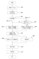
- the CPU recognizes that an image data ID has been input to the higher-level device 101 (S01).
- the image data ID may be generated using the application 151, the image data ID may be input by the image input device 104, or the image data ID stored in the higher-level device 101 or an external device may be read by reading information with the reading device 105.
- the CPU recognizes that the type of medium to be printed and the direction in which the medium is to be viewed have been selected (S02).
- the user may input the type of medium and the direction in which the medium is to be viewed using the input device 103, or the reading device 105 may read information regarding the type of medium and the direction in which the medium is to be viewed.
- the user can select the type of medium and the direction in which the medium is viewed using an input screen such as that shown in FIG. 14.
- a medium type selection field G01 for selecting the type of medium and an image layout selection field G02 (selection information input section) for selecting the layout of the image (specifying the direction in which the medium is viewed) are displayed on the monitor 102.
- a white card selection button G03 and a transparent card selection button G04 are arranged in the medium type selection field G01. In other words, here the user selects whether to create a first printed matter (FIG. 15(a)) in which the user views the image against the background of the medium, or a second printed matter (FIG. 15(b)) in which the user views the image through the medium.
- the image layout selection field G02 can be selected when a transparent card (second card Ca2) is selected in the medium type selection field G01. Therefore, if the image is to be viewed directly with the second card Ca2 in the background (image formed on the first side Ca2A of the second card), select G05, and if the image is to be viewed through the second card Ca2 (image formed on the second side Ca2B of the second card), select G06. Also, if images are to be formed on both sides of the second card Ca2, select G07 and separately set which image is to be placed on which side. Once you have finished selecting the type of medium and image placement, press the OK button G08 to finish.
- the CPU determines whether the type of medium input in step S02 is the non-transparent first card Ca1 or the transparent second card Ca2 (S03). In this embodiment, if the type of medium is the second card Ca2, when the image is viewed directly (through a protective layer) with the second card Ca2 as the background (when an image is formed on the first surface Ca2A), the process proceeds to step S05 since this is the same as the process for the first card Ca1, and when the image is viewed through the second card Ca2 (when an image is formed on the second surface Ca2B), the process proceeds to step S06.
- the CPU converts the image data ID into a mirror image in the conversion processing unit and then converts it into print data (first print data) (S05).
- the CPU converts the image data ID into print data (second print data) while keeping it as a normal image (S06).
- the CPU then sends the converted print data (or the folder in which it is stored) to the printing device 1 (S06). Steps S01 to S07 above are performed by the control unit 150 of the higher-level device 101.
- the CPU on the printing device 1 side that has received the print data uses the image forming unit B1 to perform image formation processing of the print data on the transfer film 46 (S08).
- the medium type is the first card Ca1
- a mirror image MI of the image data ID is printed on the transfer film 46
- a normal image NI of the image data ID is printed on the transfer film 46.
- a card Ca is supplied from the medium supply unit C (S09).
- the first card Ca1 or the second card Ca2 is stored in the medium supply unit C, and the card selected by the user in step S02 is set therein.
- the CPU performs a transfer process on the supplied card Ca using the transfer unit B2 (S10). This transfers the ink receiving layer 46a and protective layer 46b of the transfer film 46 on which an image has been formed onto the surface of the card Ca. Thereafter, if necessary, a decurling process is performed, and the card Ca is discharged into the media storage unit D (S11).
- the image data ID is composed of a main image ID1 and a background image ID2, and by printing the main image ID1 and the background image ID2 on top of each other, the image looks better when viewed through the second card Ca2 (this corresponds to the third printed matter shown in FIG. 15(c). If you want to create such a card, select G07 in the image layout selection field).
- the conversion processing unit converts the image data ID1 and ID2 into print data with the image data remaining as normal.
- the print data (normal image) of the main image ID1 is formed in the first region Ri1 of the transfer film 46, and the ink receiving layer 46a and protective layer 46b containing the formed image NI1 are transferred to the second card Ca2.
- the print data (normal image) of the background image ID2 is formed in the second region Ri2 of the transfer film 46, and the ink receiving layer 46a and protective layer 46b containing the formed image NI2 are transferred superimposed on the main image.
- the second card Ca2 that has been printed is in a state in which the second card Ca2, the ink receiving layer 46a (NI1) on which the main image is formed, the protective layer 46b, the ink receiving layer 46a (NI2) on which the background image is formed, and the protective layer 46b are stacked together when viewed from the user (FIG. 12C).
- main image ID1 and background image ID2 may be generated by specifying an area from a single image data ID.
- the image formed with the melt inks in the image data ID may be transferred as main image ID1
- the image formed with the sublimation inks may be transferred as background image ID2, with the two images being superimposed.
- one image data ID (FIG. 13(A)) may be printed on both sides of the second card Ca2 to make the image appear three-dimensional (corresponding to the third printed matter shown in FIG. 15(c)).
- the conversion processing unit converts the image data ID into two print data, one for a mirror image and one for a normal image, prints the mirror image print data in the first region Ri1 of the transfer film 46, and transfers the ink receiving layer 46a and protective layer 46b containing the printed image MI to the first side of the second card Ca2.
- normal image print data is printed in the second region Ri2 of the transfer film 46, and transfers the ink receiving layer 46a and protective layer 46b containing the printed image NI to the second side of the second card Ca2.
- the user can view the first image MI through the protective layer 46b transferred to the first surface of the second card Ca2, and then view the second image NI through the second card Ca2 behind it, allowing them to see superimposed images with the same orientation as the image data ID.
- the image data ID for the image the user sees through the second card Ca2 is converted into print data without being converted into a mirror image, and a normal image is formed on the transfer film 46 based on that print data.
- the ink receiving layer 46a and protective layer 46b containing the normal image NI are then transferred to the second card Ca2, so that when the image is viewed through the transparent second card Ca2, the image can be seen in the same orientation as the original image data ID.
- the normal image NI formed on the second card Ca2 is protected by the protective layer 46b, it is more durable than a normal image printed directly on the second card Ca2.
- the user sets the type of medium, but the type of medium may be detected in the card transport path of the printing device 1, and if it is the first card Ca1, a mirror image MI of the image data ID may be printed on the transfer film 46, and if it is the second card Ca2, a normal image NI of the image data ID may be printed on the transfer film 46. Furthermore, if the printing device 1 is configured to be able to detect the type of medium, the process may be stopped if the type of medium set by the user differs from the detected type of medium.
- the conversion processing unit in the control unit 150 of the higher-level device 101 determines whether to make the image data ID a mirror image or a normal image depending on the type of medium. However, if the image is to be made a mirror image after conversion to print data, the image data ID may be made a mirror image, or the image data ID may be received on the printing device 1 side and converted to print data on the printing device 1 side.
- the input image data ID is converted by mirror inversion.
- the second card Ca2 when the second card Ca2 is selected as the medium type, a selection is made as to whether to form an image on the first surface Ca2A or the second surface Ca2B. However, when the second card Ca2 is selected, it is assumed that the image will be viewed through the second card Ca2. If the first card Ca1 is selected, print data for a mirror image MI is generated so that the image data ID is a mirror image, and an image is formed on the first card Ca1. If the second card Ca2 is selected, print data for a normal image NI is generated so that the image data ID is a normal image, and an image is formed on the second card Ca2.
- the type of medium and the selection information of whether to create a first printed matter or a second printed matter are input from the monitor 102, but the selection information may be input using the operation panel unit 5, or may be input using a reading device 105 that reads two-dimensional codes such as QR codes (registered trademark) or information stored in an IC chip via wireless communication.
- a reading device 105 that reads two-dimensional codes such as QR codes (registered trademark) or information stored in an IC chip via wireless communication.
- Voice input by the user may also be used, and the selection information input unit only needs to be able to recognize that the selection information has been input as the printing system 100.
- a retransfer printer using a transfer film 46 is used as the printing device, but a direct printer that forms an image directly on the card Ca using an ink ribbon 41 without using a transfer film 46, or an inkjet printer using liquid ink may also be used.
- print data first print data
- second print data that is a mirror image of the first print data
- the printing system 100 of this embodiment whether an image is formed on the first surface Ca2A of a transparent medium (second card Ca2) to create a first printed matter in which the image is viewed directly (through the protective layer if there is one), or an image is formed on the second surface Ca2B to create a second printed matter in which the image is viewed through the second card Ca2, the user can view the image in the same orientation as the input (specified) image data ID. Therefore, since it is possible to accommodate both applications in which the image formed on the card Ca is viewed directly and applications in which the image is viewed through the second card Ca2, a single printing system 100 can meet the needs of multiple users.
- Printing device image forming device
- Thermal head Ink ribbon
- Transfer film medium
- Film transport roller part of the media transport section
- Control unit control means
- Memory storage means
- Printing system image forming system
- Object generation unit generation means
- Printer driver detection means, determination means
- B Printing section (image forming means) Mr5 Film transport motor (part of the media transport section)
Landscapes
- Engineering & Computer Science (AREA)
- Theoretical Computer Science (AREA)
- Human Computer Interaction (AREA)
- Physics & Mathematics (AREA)
- General Engineering & Computer Science (AREA)
- General Physics & Mathematics (AREA)
- Electronic Switches (AREA)
Abstract
Le problème décrit par la présente invention est de produire un système d'impression pouvant répondre aux demandes aussi bien d'utilisateurs souhaitant voir une image formée sur un côté utilisateur d'un support transparent, avec le support transparent en tant qu'arrière-plan, que d'utilisateurs souhaitant voir une image à travers le support transparent. Selon la solution de l'invention, lors de la création d'une première matière imprimée conçue de telle sorte que l'utilisateur visualise directement une image formée sur le côté utilisateur d'un support transparent (seconde carte Ca2), avec le support transparent en tant qu'arrière-plan, des premières données d'impression MI sont générées à partir de l'ID de données d'image et sont imprimées sur le support de telle sorte que, lorsque l'image formée sur le support est visualisée par l'utilisateur, l'image possède la même orientation que l'ID de données d'image, et lors de la création d'une seconde matière imprimée conçue de telle sorte que l'image est vue à travers le support, des secondes données d'impression NI sont générées à partir de l'ID de données d'image de façon à être une image miroir des premières données d'impression MI, et sont imprimées sur le support.
Applications Claiming Priority (2)
| Application Number | Priority Date | Filing Date | Title |
|---|---|---|---|
| JP2023032316 | 2023-03-02 | ||
| JP2023-032316 | 2023-03-02 |
Publications (1)
| Publication Number | Publication Date |
|---|---|
| WO2024181581A1 true WO2024181581A1 (fr) | 2024-09-06 |
Family
ID=92589988
Family Applications (1)
| Application Number | Title | Priority Date | Filing Date |
|---|---|---|---|
| PCT/JP2024/008161 Ceased WO2024181581A1 (fr) | 2023-03-02 | 2024-03-04 | Système d'impression |
Country Status (1)
| Country | Link |
|---|---|
| WO (1) | WO2024181581A1 (fr) |
Citations (9)
| Publication number | Priority date | Publication date | Assignee | Title |
|---|---|---|---|---|
| JPS61183700U (fr) * | 1985-05-08 | 1986-11-15 | ||
| JP2009104058A (ja) * | 2007-10-25 | 2009-05-14 | Konica Minolta Business Technologies Inc | 画像形成位置の調整装置、画像形成装置、画像形成位置の調整方法、および画像形成位置の調整プログラム |
| JP2015174446A (ja) * | 2014-03-17 | 2015-10-05 | 誠研科技股▲ふん▼有限公司 | 透明媒体の熱昇華印刷方法及びその製品 |
| JP2015189105A (ja) * | 2014-03-28 | 2015-11-02 | キヤノン株式会社 | 印刷装置、印刷装置の制御方法、及びプログラム |
| JP2017177591A (ja) * | 2016-03-30 | 2017-10-05 | 株式会社ユニバーサルエンターテインメント | カード、及び、カード印刷制御装置 |
| JP2019206084A (ja) * | 2018-05-28 | 2019-12-05 | 独立行政法人 国立印刷局 | 透過潜像印刷物 |
| EP3838611A1 (fr) * | 2019-12-18 | 2021-06-23 | Polska Wytwórnia Papierów Wartosciowych Spólka Akcyjna | Élément de sécurité pour un support de données, support de données et procédé de production de l'élément de sécurité et utilisation de l'élément de sécurité pour la production d'un support de données |
| JP2022050061A (ja) * | 2020-09-17 | 2022-03-30 | 大日本印刷株式会社 | 印画物製造システム及び印画物製造方法 |
| JP2022153998A (ja) * | 2021-03-30 | 2022-10-13 | 大日本印刷株式会社 | 印画物製造装置、カードセット及びカード |
-
2024
- 2024-03-04 WO PCT/JP2024/008161 patent/WO2024181581A1/fr not_active Ceased
Patent Citations (9)
| Publication number | Priority date | Publication date | Assignee | Title |
|---|---|---|---|---|
| JPS61183700U (fr) * | 1985-05-08 | 1986-11-15 | ||
| JP2009104058A (ja) * | 2007-10-25 | 2009-05-14 | Konica Minolta Business Technologies Inc | 画像形成位置の調整装置、画像形成装置、画像形成位置の調整方法、および画像形成位置の調整プログラム |
| JP2015174446A (ja) * | 2014-03-17 | 2015-10-05 | 誠研科技股▲ふん▼有限公司 | 透明媒体の熱昇華印刷方法及びその製品 |
| JP2015189105A (ja) * | 2014-03-28 | 2015-11-02 | キヤノン株式会社 | 印刷装置、印刷装置の制御方法、及びプログラム |
| JP2017177591A (ja) * | 2016-03-30 | 2017-10-05 | 株式会社ユニバーサルエンターテインメント | カード、及び、カード印刷制御装置 |
| JP2019206084A (ja) * | 2018-05-28 | 2019-12-05 | 独立行政法人 国立印刷局 | 透過潜像印刷物 |
| EP3838611A1 (fr) * | 2019-12-18 | 2021-06-23 | Polska Wytwórnia Papierów Wartosciowych Spólka Akcyjna | Élément de sécurité pour un support de données, support de données et procédé de production de l'élément de sécurité et utilisation de l'élément de sécurité pour la production d'un support de données |
| JP2022050061A (ja) * | 2020-09-17 | 2022-03-30 | 大日本印刷株式会社 | 印画物製造システム及び印画物製造方法 |
| JP2022153998A (ja) * | 2021-03-30 | 2022-10-13 | 大日本印刷株式会社 | 印画物製造装置、カードセット及びカード |
Similar Documents
| Publication | Publication Date | Title |
|---|---|---|
| US9516177B2 (en) | Image display apparatus, image display method and image display program | |
| JP6194499B2 (ja) | 印刷システムおよび印刷装置 | |
| JP7782654B2 (ja) | 印画物製造装置 | |
| JPH04103360A (ja) | 熱溶融透明バインダの転写方法 | |
| JP6346774B2 (ja) | 印刷装置および印刷システム | |
| CN108215516B (zh) | 图像形成装置、记录介质以及图像形成系统 | |
| US7787153B2 (en) | Image forming apparatus and image forming method | |
| JP6386825B2 (ja) | 印刷装置 | |
| JP2007050698A (ja) | インクリボン、熱転写方式画像形成装置、及び印刷管理情報付加方法 | |
| JP5665403B2 (ja) | プリンタ、その制御方法及びプログラム | |
| JP2021070272A (ja) | 画像形成装置 | |
| JP6579861B2 (ja) | 印刷制御装置、印刷制御方法及びプログラム | |
| JP2008087164A (ja) | 転写式印刷装置及び転写式印刷方法 | |
| JP6021425B2 (ja) | 印刷装置、印刷方法、プログラム | |
| US8520263B2 (en) | Image forming apparatus and image forming method | |
| JP7508966B2 (ja) | 印画物製造システム及び印画物製造方法 | |
| JP7631066B2 (ja) | 印刷制御装置、印刷制御方法、及び、プログラム | |
| JP2013116605A (ja) | 印刷制御装置 | |
| JP6879494B2 (ja) | 画像形成装置、プログラム、記録媒体および画像形成システム | |
| JP4609154B2 (ja) | 印字装置 | |
| JP2025068373A (ja) | 画像処理装置、画像処理方法、プログラム、および記憶媒体 | |
| JP2021088063A (ja) | 記録装置 | |
| JP2021123088A (ja) | 画像形成装置 | |
| JP2013112507A (ja) | 印刷装置、その制御方法およびプログラム | |
| JP2006175669A (ja) | 熱転写記録方法および熱転写記録装置 |
Legal Events
| Date | Code | Title | Description |
|---|---|---|---|
| 121 | Ep: the epo has been informed by wipo that ep was designated in this application |
Ref document number: 24764058 Country of ref document: EP Kind code of ref document: A1 |
|
| NENP | Non-entry into the national phase |
Ref country code: DE |
|
| 122 | Ep: pct application non-entry in european phase |
Ref document number: 24764058 Country of ref document: EP Kind code of ref document: A1 |
|
| NENP | Non-entry into the national phase |
Ref country code: JP |