WO2024190031A1 - 帯状物体の形状測定方法、帯状物体の形状制御方法、帯状物体の製造方法、帯状物体の品質管理方法、帯状物体の形状測定装置および帯状物体の製造設備 - Google Patents
帯状物体の形状測定方法、帯状物体の形状制御方法、帯状物体の製造方法、帯状物体の品質管理方法、帯状物体の形状測定装置および帯状物体の製造設備 Download PDFInfo
- Publication number
- WO2024190031A1 WO2024190031A1 PCT/JP2023/046079 JP2023046079W WO2024190031A1 WO 2024190031 A1 WO2024190031 A1 WO 2024190031A1 JP 2023046079 W JP2023046079 W JP 2023046079W WO 2024190031 A1 WO2024190031 A1 WO 2024190031A1
- Authority
- WO
- WIPO (PCT)
- Prior art keywords
- shape
- strip
- belt
- measuring
- image
- Prior art date
- Legal status (The legal status is an assumption and is not a legal conclusion. Google has not performed a legal analysis and makes no representation as to the accuracy of the status listed.)
- Ceased
Links
Images


Classifications
-
- G—PHYSICS
- G06—COMPUTING OR CALCULATING; COUNTING
- G06T—IMAGE DATA PROCESSING OR GENERATION, IN GENERAL
- G06T7/00—Image analysis
- G06T7/60—Analysis of geometric attributes
-
- G—PHYSICS
- G01—MEASURING; TESTING
- G01B—MEASURING LENGTH, THICKNESS OR SIMILAR LINEAR DIMENSIONS; MEASURING ANGLES; MEASURING AREAS; MEASURING IRREGULARITIES OF SURFACES OR CONTOURS
- G01B11/00—Measuring arrangements characterised by the use of optical techniques
- G01B11/02—Measuring arrangements characterised by the use of optical techniques for measuring length, width or thickness
- G01B11/06—Measuring arrangements characterised by the use of optical techniques for measuring length, width or thickness for measuring thickness ; e.g. of sheet material
- G01B11/0691—Measuring arrangements characterised by the use of optical techniques for measuring length, width or thickness for measuring thickness ; e.g. of sheet material of objects while moving
-
- G—PHYSICS
- G01—MEASURING; TESTING
- G01B—MEASURING LENGTH, THICKNESS OR SIMILAR LINEAR DIMENSIONS; MEASURING ANGLES; MEASURING AREAS; MEASURING IRREGULARITIES OF SURFACES OR CONTOURS
- G01B11/00—Measuring arrangements characterised by the use of optical techniques
- G01B11/24—Measuring arrangements characterised by the use of optical techniques for measuring contours or curvatures
-
- G—PHYSICS
- G01—MEASURING; TESTING
- G01B—MEASURING LENGTH, THICKNESS OR SIMILAR LINEAR DIMENSIONS; MEASURING ANGLES; MEASURING AREAS; MEASURING IRREGULARITIES OF SURFACES OR CONTOURS
- G01B11/00—Measuring arrangements characterised by the use of optical techniques
- G01B11/26—Measuring arrangements characterised by the use of optical techniques for measuring angles or tapers; for testing the alignment of axes
-
- G—PHYSICS
- G06—COMPUTING OR CALCULATING; COUNTING
- G06T—IMAGE DATA PROCESSING OR GENERATION, IN GENERAL
- G06T7/00—Image analysis
- G06T7/0002—Inspection of images, e.g. flaw detection
- G06T7/0004—Industrial image inspection
-
- G—PHYSICS
- G06—COMPUTING OR CALCULATING; COUNTING
- G06T—IMAGE DATA PROCESSING OR GENERATION, IN GENERAL
- G06T7/00—Image analysis
- G06T7/10—Segmentation; Edge detection
- G06T7/12—Edge-based segmentation
-
- G—PHYSICS
- G01—MEASURING; TESTING
- G01B—MEASURING LENGTH, THICKNESS OR SIMILAR LINEAR DIMENSIONS; MEASURING ANGLES; MEASURING AREAS; MEASURING IRREGULARITIES OF SURFACES OR CONTOURS
- G01B21/00—Measuring arrangements or details thereof, where the measuring technique is not covered by the other groups of this subclass, unspecified or not relevant
- G01B21/02—Measuring arrangements or details thereof, where the measuring technique is not covered by the other groups of this subclass, unspecified or not relevant for measuring length, width, or thickness
- G01B21/08—Measuring arrangements or details thereof, where the measuring technique is not covered by the other groups of this subclass, unspecified or not relevant for measuring length, width, or thickness for measuring thickness
- G01B21/085—Measuring arrangements or details thereof, where the measuring technique is not covered by the other groups of this subclass, unspecified or not relevant for measuring length, width, or thickness for measuring thickness using thermal means
-
- G—PHYSICS
- G06—COMPUTING OR CALCULATING; COUNTING
- G06T—IMAGE DATA PROCESSING OR GENERATION, IN GENERAL
- G06T2207/00—Indexing scheme for image analysis or image enhancement
- G06T2207/30—Subject of image; Context of image processing
- G06T2207/30108—Industrial image inspection
- G06T2207/30136—Metal
Definitions
- the present invention relates to a method for measuring the shape of a strip-like object, a method for controlling the shape of a strip-like object, a method for manufacturing a strip-like object, a quality control method for a strip-like object, an apparatus for measuring the shape of a strip-like object, and a manufacturing facility for a strip-like object.
- shape management of strip-shaped materials is important, and there has been a demand for quantification of product shapes.
- shape management of strip-shaped materials is important, and there has been a demand for quantification of product shapes.
- measuring the shape during rolling to create the desired shape of the product is important because it leads to improved product quality and operational stability by providing feedback for initial setting of rolling conditions and rolling control during rolling.
- a rectangular semi-finished product called a slab is extracted from the heating furnace at a high temperature and goes through a sizing mill, rough rolling, and finish rolling processes before being processed into a sheet and wound up into a coil.
- the reduction in the width of the steel sheet can be uneven, causing it to stretch in parts, resulting in a defective shape.
- Patent Documents 1 to 3 disclose a particularly effective method in which a laser is used to irradiate the target surface with a point or line of light and measure the shape by measuring the reflected light.
- Patent Document 4 discloses a technology that uses three line lasers whose longitudinal direction is perpendicular to the conveying direction of the steel plate as a laser irradiation method.
- line lasers are irradiated in parallel to the longitudinal direction of the steel plate so as to form three equally spaced lines, and the reflected images are acquired and the profiles of each laser are compared to eliminate the effects of vertical vibration of the steel plate.
- Patent documents 5 to 7 and non-patent document 1 disclose a technology that uses a powerful LED light source to project a striped pattern consisting of multiple lines onto the target surface, thereby increasing the number of lines projected more cheaply than with a laser, and stably measuring the shape regardless of the specularity or tilt of the target.
- strip-shaped objects include products that are ultimately wound into rolls, such as iron, paper, cloth, and non-ferrous metals such as aluminum, as well as products that are formed into rectangular plates, such as thick steel plates.
- Japanese Unexamined Patent Publication No. 56-124006 Japanese Unexamined Patent Publication No. 55-40924 Japanese Unexamined Patent Publication No. 58-11708 Japanese Unexamined Patent Publication No. 61-40503 JP 2008-58036 A JP 2011-99821 A JP 2016-65863 A
- Patent Documents 1 to 7 all involve measuring the shape of a hot-rolled steel plate by irradiating it with light from a light source and capturing the reflected light with a camera.
- advanced technology is required to perform stable measurements over a long period of time with a light source or sensor close to the steel plate during transportation, and maintenance costs are also high.
- the present invention has been made in consideration of the above, and aims to provide a method for measuring the shape of a strip-shaped object, a method for controlling the shape of a strip-shaped object, a method for manufacturing a strip-shaped object, a quality control method for a strip-shaped object, an apparatus for measuring the shape of a strip-shaped object, and a manufacturing facility for a strip-shaped object, which can be easily and stably operated without bringing a light source or sensor close to the object to be measured, and which also reduces maintenance costs, for the edge portion of the strip-shaped object.
- a method for measuring a shape of a belt-like object is a method for measuring a shape of a belt-like object, comprising the steps of:
- the angle ⁇ between the plane ⁇ , which is the reference plane of the surface of the belt-like object, and the optical axis of the camera is not 90 degrees.
- the angle ⁇ between the orthogonal projection of the optical axis of the camera onto the plane ⁇ and the conveying direction p of the belt-like object is not 0 degrees.
- the present invention also provides a method for measuring the shape of a belt-like object according to the above-mentioned (1), further comprising the steps of:
- the image processing step includes: Extracting the region of the belt-like object from the obtained image; In the extracted region, the positions of the edge portions are calculated to calculate a contour profile of the belt-like object.
- a method for measuring the shape of a belt-like object according to the present invention is the method for measuring the shape of a belt-like object according to the above (1) or (2), further comprising:
- the image processing step calculates one or more of the following indicators from the obtained contour profile of the band-like object: steepness of the edge portion of the band-like object, wave height, wave pitch, elongation amount, and elongation rate.
- a method for measuring the shape of a belt-like object according to the present invention is the method for measuring the shape of a belt-like object according to any one of (1) to (3) above, further comprising:
- the image processing step calculates the resolution in the wave height direction and the wave pitch direction from the positional relationship between the camera and the band-like object, and converts the resolution into actual dimensions.
- the method for controlling the shape of a strip-like object measures the shape of the strip-like object using the method for measuring the shape of a strip-like object described in any one of (1) to (4) above, and controls the shape of the strip-like object to a desired shape based on the measurement results.
- the method for manufacturing a strip-shaped object according to the present invention involves measuring the shape of the strip-shaped object using the method for measuring the shape of a strip-shaped object described in any one of (1) to (4) above, and manufacturing the strip-shaped object based on the measurement results.
- the quality control method for a strip-like object measures the shape of the strip-like object using the shape measurement method for a strip-like object described in any one of (1) to (4) above, and controls the quality of the strip-like object based on the measurement results.
- a shape measuring device for a belt-like object is a shape measuring device for measuring a shape of a belt-like object, comprising:
- the angle ⁇ between the plane ⁇ , which is the reference plane of the surface of the belt-like object, and the optical axis of the camera is not 90 degrees.
- the angle ⁇ between the orthogonal projection of the optical axis of the camera onto the plane ⁇ and the conveying direction p of the belt-like object is not 0 degrees.
- an imaging means for capturing an image of thermal radiation light from the belt-shaped object; an image processing means for calculating a contour profile of the belt-like object from the obtained image, thereby calculating an index of the shape of an edge portion of the belt-like object; It is equipped with the following.
- the manufacturing equipment for a strip-shaped object according to the present invention is equipped with the shape measurement device for a strip-shaped object described in (8) above.
- the method for measuring the shape of a strip-shaped object, the method for controlling the shape of a strip-shaped object, the method for manufacturing a strip-shaped object, the quality control method for a strip-shaped object, the device for measuring the shape of a strip-shaped object, and the manufacturing equipment for a strip-shaped object according to the present invention can be easily and stably operated without bringing a light source or sensor close to the object to be measured, and maintenance costs can also be reduced.
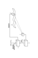
- FIG. 1 is a diagram showing a schematic configuration of an apparatus for measuring the shape of a belt-shaped object according to an embodiment of the present invention.
- FIG. 2 is a diagram showing an example of the positional relationship between the conveying direction of the steel plate and the camera, where (a) is a diagram showing the positional relationship from an oblique angle, (b) is a diagram showing the positional relationship from above, and (c) is a diagram showing the positional relationship from the direction ⁇ of (b).
- FIG. 3 is a diagram showing an example of the positional relationship between the conveying direction of the steel plate and the camera, in which the optical axis of the camera is disposed perpendicular to the conveying direction of the steel plate.
- FIG. 4 is a diagram showing an example of the positional relationship between the conveying direction of the steel plate and the camera, in which the optical axis of the camera is disposed obliquely with respect to the conveying direction of the steel plate.
- FIG. 5 is a diagram showing an example of images of a steel sheet when it is in a normal state and when it has a defective shape.
- FIG. 6 is a flow chart showing a specific process flow of the image processing steps performed by the image processing device of the apparatus for measuring the shape of a belt-like object according to the embodiment of the present invention.
- FIG. 7 is a diagram for explaining the binarization process in the image processing step of the method for measuring the shape of a band-like object according to the embodiment of the present invention.
- FIG. 8 is a diagram for explaining a contour profile calculation process in the image processing step of the method for measuring the shape of a band-like object according to an embodiment of the present invention.
- FIG. 9 shows an example of a photograph of waving occurring on a steel plate.
- FIG. 10 shows an example of an image of a stationary wave generated in a steel plate.
- FIG. 11 is a diagram showing an example of a case where it is difficult to distinguish between the plate surface of a steel plate and a structure.
- FIG. 12 is a diagram showing an example of processing using a low-pass filter that is performed when it is difficult to distinguish between the plate surface of a steel plate and a structure in a shape measuring method for a belt-shaped object according to an embodiment of the present invention.
- FIG. 9 shows an example of a photograph of waving occurring on a steel plate.
- FIG. 10 shows an example of an image of a stationary wave generated in a steel plate.
- FIG. 11 is a diagram showing an example of a case where it is difficult
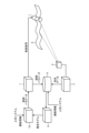
- FIG. 13 shows an example in which the apparatus for measuring the shape of a belt-shaped object according to the embodiment of the present invention is applied to determining whether or not the shape is acceptable.
- FIG. 14 shows an example in which the shape measuring device for a strip-like object according to the embodiment of the present invention is applied to rolling feedback control.
- FIG. 15 shows an example in which the shape measuring device for a strip-shaped object according to an embodiment of the present invention is applied to rolling control using machine learning.
- the following describes a method for measuring the shape of a strip-like object, a method for controlling the shape of a strip-like object, a method for manufacturing a strip-like object, a quality control method for a strip-like object, an apparatus for measuring the shape of a strip-like object, and a manufacturing facility for a strip-like object according to embodiments of the present invention, with reference to the drawings.
- the components in the following embodiments include those that are replaceable and easy for a person skilled in the art, or those that are substantially the same.
- the shape measuring device is a device for measuring the shape of a strip-shaped object.
- the shape measuring device is a device for measuring the shape of a strip-shaped object.
- the shape measuring device is applied to hot finish rolling will be described.
- the strip-shaped object to be measured is a steel plate will be described.
- the shape measured by the shape measuring device is the elongation of an edge portion of a steel plate.
- the shape measuring device includes a camera 2 and an image processing device 3. First, the details of the camera 2 will be described.
- the camera 2 is positioned so that the angle ⁇ between the "optical axis of the camera 2" and the “plane (plane ⁇ ) that is the reference plane of the strip-like object (steel plate S)” is not 90 degrees, and the angle ⁇ between the "orthogonal projection of the optical axis of the camera 2 onto the plane ⁇ " and the “conveying direction p of the strip-like object (steel plate S)” is not 0 degrees (see Figure 2).
- the camera 2 positioned in this way is then used to capture an image of the thermal radiation light of the steel plate S at the hot finish rolling exit side, which has been rolled by the rolling rolls 1.
- the steel sheet S may be threaded at a speed of, for example, 20 m/s or more, which is very high speed.
- the exposure time For example, when capturing an image at 20 m/s with a resolution of about 2 mm and pixel blurring of 1 pixel, i.e., within 2 mm, the allowable exposure time is only 0.1 ms, and the amount of light received, which is proportional to the exposure time, is also very small.
- the temperature of the steel sheet at the hot finish rolling exit is approximately 900°C.
- the peak wavelength of thermal radiation light at approximately 900°C (1200K) is 2.5 ⁇ m, and the sensitivity is low in the visible range (0.4 to 0.7 ⁇ m).
- a camera 2 equipped with an inexpensive Si imaging element and capable of using the near-infrared sensitivity range of 0.8 to 1.0 ⁇ m. By using such a camera 2, it is possible to obtain a sufficient amount of thermal radiation light at low cost.
- a camera 2 equipped with an image sensor sensitive to longer wavelengths For example, if the object to be measured is about 400°C, and introduction costs are not a consideration, a camera 2 equipped with an InGaAs image sensor sensitive to 1.2 to 1.7 ⁇ m can be used. Furthermore, if the object to be measured is about 200°C, a camera 2 equipped with an image sensor such as PbS or PbSe sensitive to 3 to 5 ⁇ m can be used. This ensures a sufficient amount of light. In this way, it is preferable to select a camera 2 equipped with an image sensor sensitive to an appropriate wavelength band depending on the transport speed, resolution, temperature, and depth of field (described below) of the object to be measured.
- FIG. 2 An example of the positional relationship between the conveying direction p of the steel sheet S and the camera 2 is shown in FIG. 2.
- FIG. 2 (a) is a diagram showing the positional relationship from an oblique angle, (b) is a diagram showing the positional relationship from above, and (c) is a diagram showing the positional relationship from the direction ⁇ n of (b).
- the direction ⁇ n is a direction in which the optical axis of the camera 2 can be seen from just beside it.
- ⁇ denotes a plane parallel to the conveying table for steel plate S
- ⁇ denotes a plane including the conveying direction p of steel plate S and the normal n of the conveying table.
- ⁇ light receiving angle ⁇
- ⁇ denotes the angle between the optical axis of camera 2 and plane ⁇
- ⁇ denotes the angle between the orthogonal projection of the optical axis of camera 2 onto plane ⁇ and conveying direction p.
- Plane ⁇ includes the surface of the strip-shaped object (steel plate S) when the strip-shaped object (steel plate S) is conveyed stably in a substantially flat shape. Therefore, plane ⁇ is also called the reference plane of the surface of the strip-shaped object (steel plate S).
- the direction of the normal n of the conveying table is the same as the normal direction of the surface of the steel plate S when the steel plate S is conveyed stably in a substantially flat shape. Therefore, the plane ⁇ includes the conveying direction p of the strip-like object (steel plate S) and is perpendicular to the normal direction of the surface of the strip-like object (steel plate S). The plane ⁇ also includes the conveying direction p of the strip-like object (steel plate S) and the normal direction of the surface of the strip-like object (steel plate S). In addition, in FIG. 2, the intersection of the plane ⁇ and the optical axis is defined as point 0. The plane perpendicular to the conveying direction of the steel plate is defined as plane ⁇ . In other words, the closer the angle ⁇ is to 90 degrees, the closer the plane ⁇ and the optical axis are to being parallel.
- the resolution rn in the wave height direction decreases, making it difficult to capture changes in the contour of the edge portion. Therefore, the closer the light-receiving angle ⁇ is to 0 degrees, the better.
- the angle ⁇ is close to 0 degrees, i.e., when the optical axis of the camera 2 is nearly parallel to the conveying direction p of the steel plate S, the resolution rp in the wave pitch direction decreases. Therefore, the closer the angle ⁇ is to 90 degrees, the better.
- the wave height to be measured is very small compared to the wave pitch, in order to capture the wave height with high accuracy, it is more preferable to make the light-receiving angle ⁇ as small as possible and to image the steel plate S at a low angle.
- the wave pitch is sufficiently larger than the wave height, so the resolution rp in the wave pitch direction may be smaller than the resolution rn in the wave height direction. Therefore, for example, as shown in Figure 3, it is preferable to set the angle ⁇ to 90 degrees, i.e., to position the camera 2 perpendicular to the conveying direction of the steel sheet S and look in from the side. However, if the angle ⁇ is not extremely small, the camera 2 may be installed at an angle to the conveying direction of the steel sheet S, for example, as shown in Figure 4.
- the distance between the steel plate S to be measured and the camera 2 is made large. The reason is that by placing the camera 2 as far away as possible from the production line, it is possible to install it in a good environment and to reduce the difference in optical conditions such as the light receiving angle ⁇ and the angle ⁇ in the width direction of the steel plate S, i.e., at both edge portions. If there is a difference in optical conditions in the width direction of the steel plate S, it will appear as a difference in appearance. Therefore, when judging by visual inspection, there is a risk of misjudging the degree of shape defect, and when quantifying the degree of shape defect by image processing, a larger correction is required. To increase the distance, it is preferable to use a telephoto lens when capturing the image. By using a telephoto lens, the difference in optical conditions can be reduced.
- the aperture value of the camera 2 is appropriately set. For example, assume that an image is to be captured of the entire surface of the steel plate S from both the front (lower) and rear (upper) edge portions. In this case, if the width of the steel plate S is d (mm), the difference ⁇ L (mm) between the distance from the camera 2 to the front edge portion and the distance from the camera 2 to the rear edge portion can be expressed by the following formula (3).
- a depth of field (range in focus) of at least ⁇ Ld (mm) is required.
- the image processing device 3 is realized by, for example, a general-purpose computer such as a workstation or a personal computer. This image processing device 3 may be installed near the camera 2, or if high speed is not required, it may be installed on the cloud.
- the image processing device 3 calculates an index of the shape of the edge portion of the steel plate S by calculating a contour profile of the steel plate S from the image captured by the camera 2. Also, as described below, the image processing device 3 extracts the area of the steel plate S from the image (step S1 in FIG. 6), and calculates the position of the edge portion in the extracted area to calculate the contour profile of the strip-shaped object of the steel plate S (step S4 in FIG. 6). Also, as described below, the image processing device 3 appropriately selects one or more of the steepness, wave height, wave pitch, elongation amount, and elongation rate of the edge portion of the steel plate S from the contour profile of the steel plate S, and calculates them as the above indexes. Below, a process of calculating an index of the shape of the edge portion of the steel plate S from the image obtained by the camera 2 using the image processing device 3 will be described.
- FIG. 5 shows an image of the steel sheet S under normal conditions
- FIG. 5 shows an image of the steel sheet S when a shape defect has occurred due to sheet elongation.
- the state of sheet elongation (particularly the elongation of the edge portion of the strip-shaped object) can be determined visually.
- the image processing device 3 calculates an index of the edge portion of the steel sheet S from the acquired image of the steel sheet S, for example, by the procedure shown in Figure 6. Note that, for ease of explanation, in the following, with regard to the vertical and horizontal axes of the image, the axis that is closer to being parallel to the transport direction of the steel sheet S is taken to be the horizontal axis.
- FIG. 7(a) is the image before binarization processing
- FIG. 7(b) is the image after binarization processing.
- blobs (lumps recognized by connecting surrounding pixels during binarization) that are candidates for plate regions may be generated.
- the plate region may be confirmed by extracting the blobs (step S3 in FIG. 6) or by determining whether or not it is a plate region based on the size, orientation, etc. of the steel plate S.
- FIG. 8 shows a method for extracting the contour of the edge portion by searching.
- FIG. 8(a) shows how the contour of the edge portion is searched, and
- FIG. 8(b) shows the contour of the extracted edge portion.
- a search may be performed from outside the plate region in the image toward the plate region, and the coordinates at which the plate region is approached may be recorded, or conversely, a search may be performed from inside the plate region to outside the plate region.
- the contour profiles of the upper and lower edge portions are calculated as one-dimensional vectors by searching the contour in the vertical direction at each point on the horizontal axis in the image.
- the image obtained in the imaging step is captured at an angle to the conveying direction of the steel plate S, so the resolution differs between the wave height direction and the wave pitch direction. Therefore, the resolution of the contour profile on the obtained image is corrected separately in the wave height direction and the wave pitch direction (step S5 in FIG. 6).
- step S5 the inclination of the optical axis of camera 2 is corrected by a rotation process so that the longitudinal direction and horizontal axis of steel plate S coincide. Since the resolution in the wave height direction, i.e., the vertical axis, is "rn (mm/pixel)" and the resolution in the wave pitch direction, i.e., the horizontal axis, is "rp (mm/pixel)", it can be converted into a contour profile of steel plate S.
- the resolution may be calculated and corrected separately for the position of the front edge and the position of the rear edge according to the distance from the camera 2.
- the resolution in the wave height direction and wave pitch direction may be calculated from the positional relationship between the camera 2 and the steel plate S, and converted into actual dimensions.
- the contour profile of the steel plate S may be calculated by performing coordinate transformation using the attitude parameters of the camera 2 and obtaining an orthogonal projection onto the plane ⁇ (see Figure 2). This makes it possible to perform strict geometric correction over the entire field of view of the camera 2.
- an index of the shape of the edge portion of the steel sheet S is calculated from the contour profile of the edge portion obtained as described above (step S6 in Figure 6).
- the index of the shape of the edge portion is often discussed in terms of a parameter called steepness, which is the ratio of wave height to wave pitch, but the index may be one or more appropriately selected from wave height, wave pitch, elongation amount, elongation rate, etc.
- steepness which is the ratio of wave height to wave pitch
- the index may be one or more appropriately selected from wave height, wave pitch, elongation amount, elongation rate, etc.
- the shape index of the edge portion of the steel sheet S obtained in this way, it becomes possible to carry out parameter control and feedback control during rolling, and further to carry out pass/fail judgment of the coil sheet shape.
- the shape index instead of just calculating the shape index from the contour profile of the steel sheet S, it is also possible to calculate, for example, the wave height, wave period, steepness, elongation amount, elongation rate, etc. from the contour profile on the image, and then later correct them using the resolution rn (mm/pixel) in the wave height direction and the resolution rp (mm/pixel) in the wave pitch direction.
- Waving is a phenomenon that occurs when the transport speed of steel plate S accelerates during transportation; when the speed on the downstream side of a certain plate-shaped point becomes faster than that on the upstream side, the plate with nowhere to go bounces upwards and forms large waves. This phenomenon can occur even if the shape of the plate edge is flat and no plate elongation has occurred, so it must be distinguished from shapes caused by plate elongation.
- Characteristics of waving include a very large wave pitch, a sudden and very large wave height, and a sudden increase in wave pitch or wave height compared to the waves before and after. Therefore, if there is a method that can directly calculate the wave pitch and wave height, then if they increase suddenly, it can be determined that this is waving rather than plate elongation. Then, data from the period determined to be waving is masked, or data from before and after is used to fill in the gaps. This makes it possible to exclude waving from the detection results for plate elongation, and to reduce the impact of the waving on the measurement results.
- FIG. 9 A method for determining waving using the variation in contour position will be described with reference to Figure 9.
- (a) to (e) in Figure 9 show examples of photographs of waving on steel plate S. Also, in Figure 9, the images are arranged in chronological order as (a), (b), (c), (d), and (e). Waving can be determined specifically by the following steps (1) to (3).
- the diagram (f) at the bottom of Figure 9 shows a schematic diagram in which the lower contour position Yt is plotted in chronological order. Using such a schematic diagram, the presence or absence of waving can be determined. As a method of determining whether waving occurs, the number of maximum and minimum values in a certain section of the progression of the lower contour position Yt can be monitored, and if the number of these values suddenly decreases, it can be determined that waving occurs.
- the presence or absence of waving is determined using the lower contour position Yt, but the presence or absence of waving may also be determined using the upper contour position. Waving may also occur independently on both edges of the steel sheet S. For this reason, it is preferable to monitor the upper contour position and the lower contour position separately to determine the presence or absence of waving.
- a fixed wave is a phenomenon in which the steel sheet S continues to be transported without changing the shape of the wave. Within the field of view of camera 2, the position and shape of the contour of the steel sheet S are observed to remain unchanged for a certain period of time. Like waving, this is a phenomenon in which the sheet speed at the front of the transport line is steadily decreasing, and the excess steel sheet S bends upwards, resulting in a constantly curved contour. Like waving, fixed waves occur even when sheet elongation is not occurring, so they must be distinguished from shapes caused by sheet elongation.
- the contour position of one point in the longitudinal direction of the steel plate S within the field of view can be monitored, and a fixed wave can be determined when the fluctuation in the contour position does not change significantly.
- FIG. 10 A method for determining whether a fixed wave exists using the variation in the contour position will be described with reference to FIG. 10.
- (a) to (e) in FIG. 10 show examples of images of fixed waves on a steel plate S.
- the images are arranged in chronological order as (a), (b), (c), (d), and (e).
- whether a fixed wave exists can be determined by the following steps (1) to (3).
- the diagram (f) at the bottom of Figure 10 shows a schematic diagram in which the upper contour position Y2t is plotted in chronological order.
- the presence or absence of a fixed wave can be determined.
- the standard deviation in a certain section of the transition of the upper contour position Y2t can be monitored, and a point where the standard deviation falls below a threshold can be determined to be a fixed wave.
- the difference between the maximum and minimum values in a certain section can be monitored, and a point where the standard deviation falls below a threshold can be determined to be a fixed wave.
- the presence or absence of a fixed wave is determined using the upper contour position Y2t, but the presence or absence of a fixed wave may also be determined using the lower contour position.
- fixed waves may occur independently for both edges. For this reason, it is preferable to monitor the upper contour position and the lower contour position separately to determine the presence or absence of a fixed wave.
- a fixed wave is not determined to be present when the index of plate elongation is below a threshold, but is determined to be present only when it is above the threshold.
- Other methods include a method in which an evaluation function is designed and the determination is made based on a threshold, or a method in which a visual determination of whether a fixed wave has occurred is used as correct answer data, and a determination machine that uses machine learning to determine whether a fixed wave has occurred can be created to make the determination.
- step S1 the brightness of the thermal radiation light varies depending on the temperature of the object being measured. Therefore, if the binarization process is performed with a fixed value, there is a problem that when the steel plate S is bright, part of the background will be detected as the plate area, and conversely, when the steel plate S is dark, the background cannot be detected.
- One method of brightness correction is to multiply the brightness of the entire image by a fixed value so that a representative value such as the maximum, average, median, or percentile of the brightness of the entire image becomes a target value. Dark current correction may also be performed before multiplication.
- the thermal radiation light emitted from the steel sheet S is irradiated onto structures such as transport rolls and tables, and the structures are captured brightly in the image, making it difficult to distinguish them from the sheet surface.
- the sheet surface appears bright in the image because it receives the thermal radiation light directly, but the structures are often darker than the sheet surface because they are reflections of the thermal radiation light emitted from the sheet surface.
- the binarization threshold value that can distinguish the structure from the plate by performing the brightness correction described above may be determined as a fixed value, but more stable detection is possible by automatically detecting the valleys from the shape of the histogram of the entire image.
- a low-pass filter is applied to the brightness histogram itself, making it possible to stably calculate the minimum value by differentiation processing, search processing, etc.
- FIG. 12(a) is an example of a brightness histogram, and is a graph with brightness on the horizontal axis and the number of pixels N on the vertical axis.
- FIG. 12(b) is an example of applying a low-pass filter to the brightness direction of the brightness histogram.
- the area separated by a dotted line corresponds to the binarization threshold.
- a machine learning classifier may be used to estimate an index of the shape of the edge portion of the steel sheet S from an image.
- learning data is created by first linking the index of the shape of the edge portion measured visually or by some other method as a correct answer to the obtained image of the steel sheet S. Then, using the created learning data and a machine learning method, a classifier is generated that takes an image as input and outputs an index of the shape of the edge portion, and this classifier is used to calculate the index of the shape of the edge portion of the target steel sheet S.
- the input data to the machine learning and classifier may be features calculated from the image, in addition to the image.
- a convolutional neural network or the like may be used.
- the image processing device 3 calculates an index (shape data) of the shape of the edge portion of the steel plate S from the image captured by the camera 2, and sends it to the pass/fail judgment device 6.
- the pass/fail judgment device 6 judges whether the shape is pass/fail based on the steel plate information (e.g., plate thickness, plate width, steel type, temperature, etc.) obtained from the upper system and the index of the shape of the edge portion of the steel plate S.
- the pass/fail judgment result is sent to the upper system.
- the upper system judges whether correction is necessary, whether the defective shape portion should be cut off, whether rolling can be performed in the next process, etc. In this way, by utilizing the index of the shape of the edge portion of the steel plate S in the action of the next process, it is possible to prevent problems and improve product quality.
- the rolling control system in Fig. 14 includes a camera 2, an image processing device 3, and a rolling control device 7.
- the image processing device 3 calculates an index of the shape of the edge portion of the steel sheet S from the image captured by the camera 2, and sends it to the rolling control device 7.
- the rolling control device 7 calculates control parameters using the index of the shape of the edge portion based on the steel sheet information (e.g., sheet thickness, sheet width, steel type, temperature, etc.) acquired from the upper system, other measurement data such as the sheet passing position, and the index of the shape of the edge portion of the steel sheet S.
- the rolling control device 7 also performs feedback control such as leveling by sending a control signal to the rolling rolls 1. By performing such feedback control, it is possible to stabilize the shape of the product and reduce shape defects themselves.
- the rolling control system in Fig. 15 includes a camera 2, an image processing device 3, a rolling control device 7, a data server 8, a machine learning device 9, and a control parameter estimation device 10.
- the image processing device 3 calculates an index of the shape of the edge portion of the steel plate S from the image captured by the camera 2, and transmits it to the data server 8.
- the data server 8 stores the index of the shape of the edge portion in a state linked to the steel plate information (e.g. plate thickness, plate width, steel type, temperature, etc.) acquired from the upper system and the control parameters during rolling.
- the machine learning device 9 uses machine learning to construct a model that estimates control parameters for rolling while suppressing shape defects.
- the estimated model is sent to the control parameter estimation device 10, which estimates control parameters based on the steel plate information obtained from the higher-level system.
- the control parameters are sent to the rolling control device 7.
- the rolling control device 7 performs preset control such as leveling by sending control signals to the rolling rolls 1. By performing such preset control, the shape of the product can be stabilized and shape defects themselves can be reduced.
- control parameters in preset control are described, but machine learning may also be applied to calculate the control parameters in feedback control.
- machine learning may also be applied to calculate the control parameters in feedback control.
- by combining preset control and feedback control it is possible to further improve the shape quality of the product.
- the shape measuring device for a strip-shaped object according to the embodiment can also be provided as part of a manufacturing facility for strip-shaped objects.
- the method for measuring the shape of a strip-like object according to the embodiment can also be applied to a method for controlling the shape of a strip-like object.
- the shape of the strip-like object is measured using the method for measuring the shape of a strip-like object described above, and the shape of the strip-like object is controlled to a desired shape based on the measurement results.
- the method for measuring the shape of a strip-shaped object according to the embodiment can also be applied to a method for manufacturing a strip-shaped object.
- the shape of the strip-shaped object is measured using the method for measuring the shape of a strip-shaped object described above, and the strip-shaped object is manufactured based on the measurement results.
- the method for measuring the shape of a strip-like object according to the embodiment can also be applied to a method for controlling the quality of a strip-like object.
- the shape of the strip-like object is measured using the method for measuring the shape of a strip-like object described above, and the quality of the strip-like object is controlled based on the measurement results.
- the method for measuring the shape of a strip-like object, the method for controlling the shape of a strip-like object, the method for manufacturing a strip-like object, the quality control method for a strip-like object, the device for measuring the shape of a strip-like object, and the manufacturing equipment for a strip-like object provide the following advantages.
- an imaging element for the camera 2 that is suitable for the temperature of the target, it is possible to efficiently receive thermal radiation light.
- sensitivity can be increased by using the near-infrared components of a Si imaging element, and clear, blur-free images can be obtained by shortening the exposure time, even for steel plate S that is being transported at high speed.
- the contours of both edges of the steel plate S can be clearly captured and an index of the shape of the edge portions can be quantitatively calculated, so that the sheet elongation can be clearly captured.
- a higher effect can be obtained by capturing an image of the strip-like object (steel plate S) from the width direction (i.e., a direction in which the angle ⁇ is close to 90 degrees).
- a higher effect can be obtained by capturing an image at a low angle (i.e., a direction in which the angle ⁇ is close to 0 degrees).
- an even higher effect can be obtained by capturing an image from a direction in which the angle ⁇ is close to 90 degrees and the angle ⁇ is close to 0 degrees.
- the present invention has been described with reference to the steel plate S at the finish rolling exit side of the hot rolling process, it goes without saying that it can also be applied to other high-temperature plate-shaped steel materials such as thick steel plates and slabs. Furthermore, it goes without saying that the present invention can be applied to various strip-shaped objects made of different materials, not just strip-shaped objects in the steelmaking process, as long as the thermal radiation light of the object to be measured can be obtained. Furthermore, the present invention is more effective when the elongation of the edge of a strip-shaped object is the object of shape measurement, and is therefore preferable.
- the method for measuring the shape of a strip-like object, the method for controlling the shape of a strip-like object, the method for manufacturing a strip-like object, the quality control method for a strip-like object, the shape measuring device for a strip-like object, and the manufacturing equipment for a strip-like object according to the present invention have been specifically described above using a form for carrying out the invention and examples, but the spirit of the present invention is not limited to these descriptions and must be interpreted broadly based on the claims. Furthermore, it goes without saying that various changes, modifications, etc. based on these descriptions are also included in the spirit of the present invention.
Landscapes
- Physics & Mathematics (AREA)
- Engineering & Computer Science (AREA)
- General Physics & Mathematics (AREA)
- Computer Vision & Pattern Recognition (AREA)
- Theoretical Computer Science (AREA)
- Geometry (AREA)
- Quality & Reliability (AREA)
- Length Measuring Devices By Optical Means (AREA)
- Image Analysis (AREA)
Abstract
Description
前記帯状物体の表面の基準面である平面αとカメラの光軸とがなす角θが、90度とならないように、
かつ、前記カメラの光軸の前記平面αへの正射影と前記帯状物体の搬送方向pとがなす角φが、0度とならないように、
前記帯状物体の熱輻射光の画像を撮像する撮像ステップと、
得られた画像から前記帯状物体の輪郭プロファイルを算出することにより、前記帯状物体のエッジ部の形状の指標を算出する画像処理ステップと、
を含むものである。
前記画像処理ステップは、
得られた画像から前記帯状物体の領域を抽出し、
抽出した領域において、前記エッジ部の位置を算出することにより、前記帯状物体の輪郭プロファイルを算出するものである。
前記画像処理ステップは、得られた前記帯状物体の輪郭プロファイルから、前記帯状物体のエッジ部の急峻度、波高さ、波ピッチ、伸び量、伸び率のいずれか一つ以上を、前記指標として算出するものである。
前記画像処理ステップは、前記カメラと前記帯状物体との位置関係から、波高さ方向および波ピッチ方向の分解能を算出し、実際の寸法に換算するものである。
前記帯状物体の表面の基準面である平面αとカメラの光軸とがなす角θが、90度とならないように、
かつ、前記カメラの光軸の前記平面αへの正射影と前記帯状物体の搬送方向pとがなす角φが、0度とならないように、
前記帯状物体の熱輻射光の画像を撮像する撮像手段と、
得られた画像から前記帯状物体の輪郭プロファイルを算出することにより、前記帯状物体のエッジ部の形状の指標を算出する画像処理手段と、
を備えるものである。
実施形態に係る帯状物体の形状測定装置について、図1~図12を参照しながら説明する。形状測定装置は、帯状物体の形状を測定するための装置である。以下では、形状測定装置を熱間仕上げ圧延に適用した場合について説明する。また、以下では、測定対象である帯状物体が鋼板である場合について説明する。また、以下では、形状測定装置が測定する形状が、鋼板のエッジ部の伸びである場合について説明する。
第一に、鮮明な画像を得るための光量を確保する。熱間仕上げ圧延出側では、例えば20m/s以上の速度で鋼板Sが通板されることもあるため、非常に高速である。高速な対象をブレなく鮮明に捉えるためには、露光時間を短くすることが好ましい。例えば20m/sで2mm程度の分解能、画素ブレ量を1画素、すなわち2mm以内で撮像する場合、許容される露光時間はわずか0.1msとなり、露光時間に比例する受光量も非常に小さくなる。
第二に、鋼板Sの形状を鮮明に撮像するために、測定対象の鋼板Sとカメラ2との位置関係を検討する。ここで、鋼板Sのエッジ伸びに着目し、エッジ部の形状変化を鋼板Sの輪郭として捉えることを考える。鋼板Sの搬送方向pとカメラ2との位置関係の一例を図2に示す。図2において、(a)は当該位置関係を斜めから見た図であり、(b)は当該位置関係を上から見た図であり、(c)は当該位置関係を(b)の方向δnから見た図である。ここで方向δnは、カメラ2の光軸を真横から見ることができる方向である。このような方向δnを定義することにより、後述する受光角θの大きさを正確に見ることができる。
rp=r/sinφ ・・・(2)
第三として、測定対象の鋼板Sとカメラ2との距離を大きくとる。その理由は、カメラ2を製造ラインからなるべく離すことにより、良好な環境に設置できるとともに、鋼板Sの板幅方向、すなわち両エッジ部における受光角θや角φ等の光学条件の差を小さくすることができるためである。鋼板Sの板幅方向で光学条件に差がある場合、見え方の違いとして現れる。そのため、目視で判断する場合は形状不良の程度を見誤るおそれがあり、画像処理により形状不良の程度を定量化する場合はより大きい補正が要求される。距離を大きくとるには、撮像の際に望遠レンズを用いることが好ましい。望遠レンズを用いることにより、光学条件の差を小さくすることができる。
第四として、被写界深度を確保するために、カメラ2の絞り値を適正に定める。例えば鋼板Sの手前側(下側)および奥側(上側)の両エッジ部にかけて、板全面を撮像しようとした場合を仮定する。この場合、鋼板Sの板幅をd(mm)とすると、カメラ2から手前側のエッジ部までの距離と、カメラ2から奥側のエッジ部までの距離との差ΔL(mm)は、下記式(3)により表すことができる。
(ii)sinカーブをフィッティングし、振幅および周期から、波高さおよび波ピッチを算出する。急峻度は、波高さと波ピッチの比として算出する。
(iii)輪郭長さから板伸びの伸び量、伸び率を算出し、上記の非特許文献2の手法により急峻度を直接算出する。
(2)(1)で決定した画像幅方向位置Xtに対して、各画像の下側輪郭位置Ytを算出する。この下側輪郭位置Ytは、画像横方向中央における下側の輪郭位置である。
(3)算出した下側輪郭位置Ytの変動を監視し、大きく変動した箇所を検出する。
(2)(1)で決定した画像幅方向位置X2tに対して、各画像の上側輪郭位置Y2tを算出する。この上側輪郭位置Y2tは、画像横方向中央における上側の輪郭位置である。
(3)算出した上側輪郭位置Y2tの変動を監視し、ほぼ変動しない箇所を検出する。
実施形態に係る帯状物体の形状測定装置を形状合否判定に適用した例について、図13を参照しながら説明する。図13の合否判定システムは、カメラ2と、画像処理装置3と、合否判定装置6と、を備えている。
実施形態に係る帯状物体の形状測定装置を圧延フィードバック制御に適用した例について、図14を参照しながら説明する。図14の圧延制御システムは、カメラ2と、画像処理装置3と、圧延制御装置7と、を備えている。
実施形態に係る帯状物体の形状測定装置を、機械学習を用いた圧延制御に適用した例について、図15を参照しながら説明する。図15の圧延制御システムは、カメラ2と、画像処理装置3と、圧延制御装置7と、データサーバ8と、機械学習装置9と、制御パラメータ推定装置10と、を備えている。
2 カメラ
3 画像処理装置
6 合否判定装置
7 圧延制御装置
8 データサーバ
9 機械学習装置
10 制御パラメータ推定装置
S 鋼板
Claims (9)
- 帯状物体の形状を測定する形状測定方法であって、
前記帯状物体の表面の基準面である平面αとカメラの光軸とがなす角θが、90度とならないように、
かつ、前記カメラの光軸の前記平面αへの正射影と前記帯状物体の搬送方向pとがなす角φが、0度とならないように、
前記帯状物体の熱輻射光の画像を撮像する撮像ステップと、
得られた画像から前記帯状物体の輪郭プロファイルを算出することにより、前記帯状物体のエッジ部の形状の指標を算出する画像処理ステップと、
を含む帯状物体の形状測定方法。 - 前記画像処理ステップは、
得られた画像から前記帯状物体の領域を抽出し、
抽出した領域において、前記エッジ部の位置を算出することにより、前記帯状物体の輪郭プロファイルを算出する、
請求項1に記載の帯状物体の形状測定方法。 - 前記画像処理ステップは、得られた前記帯状物体の輪郭プロファイルから、前記帯状物体のエッジ部の急峻度、波高さ、波ピッチ、伸び量、伸び率のいずれか一つ以上を、前記指標として算出する請求項1または請求項2に記載の帯状物体の形状測定方法。
- 前記画像処理ステップは、前記カメラと前記帯状物体との位置関係から、波高さ方向および波ピッチ方向の分解能を算出し、実際の寸法に換算する請求項1から請求項3のいずれか一項に記載の帯状物体の形状測定方法。
- 請求項1から請求項4のいずれか一項に記載の帯状物体の形状測定方法によって前記帯状物体の形状を測定し、その測定結果に基づいて前記帯状物体の形状が所望の形状となるように制御する帯状物体の形状制御方法。
- 請求項1から請求項4のいずれか一項に記載の帯状物体の形状測定方法によって前記帯状物体の形状を測定し、その測定結果に基づいて前記帯状物体を製造する帯状物体の製造方法。
- 請求項1から請求項4のいずれか一項に記載の帯状物体の形状測定方法によって前記帯状物体の形状を測定し、その測定結果に基づいて前記帯状物体の品質を管理する帯状物体の品質管理方法。
- 帯状物体の形状を測定する形状測定装置であって、
前記帯状物体の表面の基準面である平面αとカメラの光軸とがなす角θが、90度とならないように、
かつ、前記カメラの光軸の前記平面αへの正射影と前記帯状物体の搬送方向pとがなす角φが、0度とならないように、
前記帯状物体の熱輻射光の画像を撮像する撮像手段と、
得られた画像から前記帯状物体の輪郭プロファイルを算出することにより、前記帯状物体のエッジ部の形状の指標を算出する画像処理手段と、
を備える帯状物体の形状測定装置。 - 請求項8に記載の帯状物体の形状測定装置を備える帯状物体の製造設備。
Priority Applications (4)
| Application Number | Priority Date | Filing Date | Title |
|---|---|---|---|
| CN202380095499.6A CN120858264A (zh) | 2023-03-10 | 2023-12-22 | 带状物体的形状测定方法及装置、控制方法、制造方法及设备及质量管理方法 |
| EP23927633.0A EP4664062A4 (en) | 2023-03-10 | 2023-12-22 | METHOD FOR SHAPE MEASURING BELT-SHAPED OBJECTS, METHOD FOR SHAPE CONTROLLING BELT-SHAPED OBJECTS, METHOD FOR MANUFACTURING BELT-SHAPED OBJECTS, METHOD FOR QUALITY MANAGEMENT OF BELT-SHAPED OBJECTS, DEVICE FOR SHAPE MEASURING BELT-SHAPED OBJECTS, AND EQUIPMENT FOR MANUFACTURING BELT-SHAPED OBJECTS |
| JP2024540584A JP7578215B1 (ja) | 2023-03-10 | 2023-12-22 | 帯状物体の形状測定方法、帯状物体の形状制御方法、帯状物体の製造方法、帯状物体の品質管理方法、帯状物体の形状測定装置および帯状物体の製造設備 |
| KR1020257029115A KR20250139388A (ko) | 2023-03-10 | 2023-12-22 | 띠형상 물체의 형상 측정 방법, 띠형상 물체의 형상 제어 방법, 띠형상 물체의 제조 방법, 띠형상 물체의 품질 관리 방법, 띠형상 물체의 형상 측정 장치 및 띠형상 물체의 제조 설비 |
Applications Claiming Priority (2)
| Application Number | Priority Date | Filing Date | Title |
|---|---|---|---|
| JP2023-037229 | 2023-03-10 | ||
| JP2023037229 | 2023-03-10 |
Publications (1)
| Publication Number | Publication Date |
|---|---|
| WO2024190031A1 true WO2024190031A1 (ja) | 2024-09-19 |
Family
ID=92754643
Family Applications (1)
| Application Number | Title | Priority Date | Filing Date |
|---|---|---|---|
| PCT/JP2023/046079 Ceased WO2024190031A1 (ja) | 2023-03-10 | 2023-12-22 | 帯状物体の形状測定方法、帯状物体の形状制御方法、帯状物体の製造方法、帯状物体の品質管理方法、帯状物体の形状測定装置および帯状物体の製造設備 |
Country Status (6)
| Country | Link |
|---|---|
| EP (1) | EP4664062A4 (ja) |
| JP (1) | JP7578215B1 (ja) |
| KR (1) | KR20250139388A (ja) |
| CN (1) | CN120858264A (ja) |
| TW (1) | TWI885655B (ja) |
| WO (1) | WO2024190031A1 (ja) |
Families Citing this family (3)
| Publication number | Priority date | Publication date | Assignee | Title |
|---|---|---|---|---|
| JP7665854B1 (ja) * | 2024-11-29 | 2025-04-21 | Primetals Technologies Japan株式会社 | 金属帯板の板形状検出装置、及び圧延機、並びに検出方法 |
| JP7661600B1 (ja) * | 2024-11-29 | 2025-04-14 | Primetals Technologies Japan株式会社 | 金属帯板の板形状検出装置、及び圧延機、並びに検出方法 |
| JP7665855B1 (ja) * | 2024-11-29 | 2025-04-21 | Primetals Technologies Japan株式会社 | 金属帯板の板形状検出装置、及び圧延機、並びに検出方法 |
Citations (11)
| Publication number | Priority date | Publication date | Assignee | Title |
|---|---|---|---|---|
| JPS5540924A (en) | 1978-09-16 | 1980-03-22 | Sumitomo Metal Ind Ltd | Flatness measuring method for flat plate |
| JPS56124006A (en) | 1980-02-05 | 1981-09-29 | Sumitomo Metal Ind Ltd | Measuring method for flatness of plane plate |
| JPS5811708A (ja) | 1981-07-13 | 1983-01-22 | Showa Denko Kk | Cv鋳鉄用黒鉛球状化抑制剤の製造法 |
| JPS6140503A (ja) | 1984-07-31 | 1986-02-26 | Sumitomo Metal Ind Ltd | 連続搬送鋼板の平坦度測定方法 |
| JPH10318719A (ja) * | 1997-05-15 | 1998-12-04 | Mitsubishi Heavy Ind Ltd | 板幅・蛇行検出方法及び装置 |
| JP2000357228A (ja) * | 1999-06-14 | 2000-12-26 | Sumitomo Metal Ind Ltd | エッジ検出方法、エッジ検出装置、及び記録媒体 |
| JP2008058036A (ja) | 2006-08-29 | 2008-03-13 | Sumitomo Metal Ind Ltd | 板材の平坦度測定方法及び板材の平坦度測定装置 |
| JP2011099821A (ja) | 2009-11-09 | 2011-05-19 | Sumitomo Metal Ind Ltd | 板材の光学式形状測定方法及び測定装置 |
| JP2016065863A (ja) | 2014-09-22 | 2016-04-28 | 新日鐵住金株式会社 | 鋼板形状測定装置及びその方法、並びにそれらを用いた鋼板製造装置及びその方法 |
| WO2018168700A1 (ja) * | 2017-03-14 | 2018-09-20 | Jfeスチール株式会社 | 帯状体の蛇行量測定方法および装置並びに帯状体の蛇行異常検出方法および装置 |
| JP2019181562A (ja) * | 2018-04-10 | 2019-10-24 | Jfeスチール株式会社 | 圧延材の反り量測定方法及び反り量測定装置 |
Family Cites Families (3)
| Publication number | Priority date | Publication date | Assignee | Title |
|---|---|---|---|---|
| JP5206155B2 (ja) * | 2008-06-30 | 2013-06-12 | Jfeスチール株式会社 | 熱間圧延における近赤外線カメラを用いた熱延金属帯の冷却制御方法および熱延金属帯の製造方法 |
| US10046918B2 (en) * | 2016-10-28 | 2018-08-14 | Embraer S.A. | Continuous belt conveyor monitoring systems and methods |
| US11833560B2 (en) * | 2019-07-22 | 2023-12-05 | Jfe Steel Corporation | Meandering control method, meandering control device, and hot rolling equipment for hot rolled steel strip |
-
2023
- 2023-12-22 KR KR1020257029115A patent/KR20250139388A/ko active Pending
- 2023-12-22 EP EP23927633.0A patent/EP4664062A4/en active Pending
- 2023-12-22 CN CN202380095499.6A patent/CN120858264A/zh active Pending
- 2023-12-22 TW TW112150332A patent/TWI885655B/zh active
- 2023-12-22 JP JP2024540584A patent/JP7578215B1/ja active Active
- 2023-12-22 WO PCT/JP2023/046079 patent/WO2024190031A1/ja not_active Ceased
Patent Citations (11)
| Publication number | Priority date | Publication date | Assignee | Title |
|---|---|---|---|---|
| JPS5540924A (en) | 1978-09-16 | 1980-03-22 | Sumitomo Metal Ind Ltd | Flatness measuring method for flat plate |
| JPS56124006A (en) | 1980-02-05 | 1981-09-29 | Sumitomo Metal Ind Ltd | Measuring method for flatness of plane plate |
| JPS5811708A (ja) | 1981-07-13 | 1983-01-22 | Showa Denko Kk | Cv鋳鉄用黒鉛球状化抑制剤の製造法 |
| JPS6140503A (ja) | 1984-07-31 | 1986-02-26 | Sumitomo Metal Ind Ltd | 連続搬送鋼板の平坦度測定方法 |
| JPH10318719A (ja) * | 1997-05-15 | 1998-12-04 | Mitsubishi Heavy Ind Ltd | 板幅・蛇行検出方法及び装置 |
| JP2000357228A (ja) * | 1999-06-14 | 2000-12-26 | Sumitomo Metal Ind Ltd | エッジ検出方法、エッジ検出装置、及び記録媒体 |
| JP2008058036A (ja) | 2006-08-29 | 2008-03-13 | Sumitomo Metal Ind Ltd | 板材の平坦度測定方法及び板材の平坦度測定装置 |
| JP2011099821A (ja) | 2009-11-09 | 2011-05-19 | Sumitomo Metal Ind Ltd | 板材の光学式形状測定方法及び測定装置 |
| JP2016065863A (ja) | 2014-09-22 | 2016-04-28 | 新日鐵住金株式会社 | 鋼板形状測定装置及びその方法、並びにそれらを用いた鋼板製造装置及びその方法 |
| WO2018168700A1 (ja) * | 2017-03-14 | 2018-09-20 | Jfeスチール株式会社 | 帯状体の蛇行量測定方法および装置並びに帯状体の蛇行異常検出方法および装置 |
| JP2019181562A (ja) * | 2018-04-10 | 2019-10-24 | Jfeスチール株式会社 | 圧延材の反り量測定方法及び反り量測定装置 |
Non-Patent Citations (3)
| Title |
|---|
| "Development of shape meter employing LED dot pattern projection method for hot strip finishing mill", THE IRON AND STEEL INSTITUTE OF JAPAN, vol. 105, no. 1, 2019, pages 20 - 29 |
| KANESHIGE: "Thermal measurement with radiation thermometer", JAPAN SOCIETY OF POLYMER PROCESSING, vol. 32, no. 4, 2020, pages 121 - 124 |
| See also references of EP4664062A1 |
Also Published As
| Publication number | Publication date |
|---|---|
| CN120858264A (zh) | 2025-10-28 |
| EP4664062A1 (en) | 2025-12-17 |
| TWI885655B (zh) | 2025-06-01 |
| TW202436832A (zh) | 2024-09-16 |
| JPWO2024190031A1 (ja) | 2024-09-19 |
| JP7578215B1 (ja) | 2024-11-06 |
| EP4664062A4 (en) | 2026-04-29 |
| KR20250139388A (ko) | 2025-09-23 |
Similar Documents
| Publication | Publication Date | Title |
|---|---|---|
| JP7578215B1 (ja) | 帯状物体の形状測定方法、帯状物体の形状制御方法、帯状物体の製造方法、帯状物体の品質管理方法、帯状物体の形状測定装置および帯状物体の製造設備 | |
| TWI425205B (zh) | 用以偵測材料中缺陷之方法以及用於該方法之系統 | |
| KR101734748B1 (ko) | 판재의 평탄도 측정 방법, 판재의 평탄도 측정 장치 및 강판의 제조 방법 | |
| JP4896828B2 (ja) | 形状検出方法及び形状検出装置 | |
| US20100236310A1 (en) | Edge flatness monitoring | |
| US20040095584A1 (en) | Process and device for measuring distances on strips of bright metal strip | |
| JP2001321829A (ja) | 鋼板の製造方法および製造装置 | |
| JP2017062181A (ja) | 表面疵検査装置及び表面疵検査方法 | |
| JP7571923B1 (ja) | 帯状物体の形状測定方法、帯状物体の形状制御方法、帯状物体の製造方法、帯状物体の品質管理方法、帯状物体の形状測定装置および帯状物体の製造設備 | |
| JP7047995B1 (ja) | 鋼板の蛇行量測定装置、鋼板の蛇行量測定方法、熱間圧延鋼帯の熱間圧延設備、及び熱間圧延鋼帯の熱間圧延方法 | |
| JP7222415B2 (ja) | 熱間圧延鋼帯の蛇行量測定装置及び熱間圧延鋼帯の蛇行量測定方法 | |
| JP7111142B2 (ja) | 圧延材の入射角検出方法及び装置 | |
| Schausberger et al. | Two illustrative examples to show the potential of thermography for process monitoring and control in hot rolling | |
| KR100381098B1 (ko) | 컬러 영상을 이용한 슬라브의 캠버 측정시스템 | |
| JP7841498B2 (ja) | 帯状基材の形状測定方法、品質管理方法および製造方法、ならびに、帯状基材の形状測定装置および製造設備 | |
| JP2026000851A (ja) | 板状物体の形状測定方法、板状物体の形状制御方法、板状物体の製造方法、板状物体の品質管理方法、板状物体の形状測定装置および板状物体の製造設備 | |
| JP2019124469A (ja) | 表面検査装置 |
Legal Events
| Date | Code | Title | Description |
|---|---|---|---|
| WWE | Wipo information: entry into national phase |
Ref document number: 2024540584 Country of ref document: JP |
|
| 121 | Ep: the epo has been informed by wipo that ep was designated in this application |
Ref document number: 23927633 Country of ref document: EP Kind code of ref document: A1 |
|
| WWE | Wipo information: entry into national phase |
Ref document number: 202517078962 Country of ref document: IN |
|
| WWE | Wipo information: entry into national phase |
Ref document number: 202380095499.6 Country of ref document: CN |
|
| WWE | Wipo information: entry into national phase |
Ref document number: 2025124640 Country of ref document: RU |
|
| WWP | Wipo information: published in national office |
Ref document number: 202517078962 Country of ref document: IN |
|
| REG | Reference to national code |
Ref country code: BR Ref legal event code: B01A Ref document number: 112025019181 Country of ref document: BR |
|
| WWP | Wipo information: published in national office |
Ref document number: 2025124640 Country of ref document: RU |
|
| NENP | Non-entry into the national phase |
Ref country code: DE |
|
| WWP | Wipo information: published in national office |
Ref document number: 202380095499.6 Country of ref document: CN |
|
| WWP | Wipo information: published in national office |
Ref document number: 2023927633 Country of ref document: EP |