WO2024190861A1 - Vitre de véhicule et unité de vitre de véhicule - Google Patents
Vitre de véhicule et unité de vitre de véhicule Download PDFInfo
- Publication number
- WO2024190861A1 WO2024190861A1 PCT/JP2024/009966 JP2024009966W WO2024190861A1 WO 2024190861 A1 WO2024190861 A1 WO 2024190861A1 JP 2024009966 W JP2024009966 W JP 2024009966W WO 2024190861 A1 WO2024190861 A1 WO 2024190861A1
- Authority
- WO
- WIPO (PCT)
- Prior art keywords
- glass plate
- glass
- vehicle
- light
- main surface
- Prior art date
- Legal status (The legal status is an assumption and is not a legal conclusion. Google has not performed a legal analysis and makes no representation as to the accuracy of the status listed.)
- Ceased
Links
Images



Classifications
-
- B—PERFORMING OPERATIONS; TRANSPORTING
- B32—LAYERED PRODUCTS
- B32B—LAYERED PRODUCTS, i.e. PRODUCTS BUILT-UP OF STRATA OF FLAT OR NON-FLAT, e.g. CELLULAR OR HONEYCOMB, FORM
- B32B17/00—Layered products essentially comprising sheet glass, or glass, slag, or like fibres
-
- B—PERFORMING OPERATIONS; TRANSPORTING
- B60—VEHICLES IN GENERAL
- B60J—WINDOWS, WINDSCREENS, NON-FIXED ROOFS, DOORS, OR SIMILAR DEVICES FOR VEHICLES; REMOVABLE EXTERNAL PROTECTIVE COVERINGS SPECIALLY ADAPTED FOR VEHICLES
- B60J1/00—Windows; Windscreens; Accessories therefor
-
- B—PERFORMING OPERATIONS; TRANSPORTING
- B60—VEHICLES IN GENERAL
- B60Q—ARRANGEMENT OF SIGNALLING OR LIGHTING DEVICES, THE MOUNTING OR SUPPORTING THEREOF OR CIRCUITS THEREFOR, FOR VEHICLES IN GENERAL
- B60Q3/00—Arrangement of lighting devices for vehicle interiors; Lighting devices specially adapted for vehicle interiors
- B60Q3/20—Arrangement of lighting devices for vehicle interiors; Lighting devices specially adapted for vehicle interiors for lighting specific fittings of passenger or driving compartments; mounted on specific fittings of passenger or driving compartments
- B60Q3/208—Sun roofs; Windows
-
- B—PERFORMING OPERATIONS; TRANSPORTING
- B60—VEHICLES IN GENERAL
- B60Q—ARRANGEMENT OF SIGNALLING OR LIGHTING DEVICES, THE MOUNTING OR SUPPORTING THEREOF OR CIRCUITS THEREFOR, FOR VEHICLES IN GENERAL
- B60Q3/00—Arrangement of lighting devices for vehicle interiors; Lighting devices specially adapted for vehicle interiors
- B60Q3/60—Arrangement of lighting devices for vehicle interiors; Lighting devices specially adapted for vehicle interiors characterised by optical aspects
- B60Q3/62—Arrangement of lighting devices for vehicle interiors; Lighting devices specially adapted for vehicle interiors characterised by optical aspects using light guides
- B60Q3/64—Arrangement of lighting devices for vehicle interiors; Lighting devices specially adapted for vehicle interiors characterised by optical aspects using light guides for a single lighting device
Definitions
- the present invention relates to vehicle glass and vehicle glass units.
- a known configuration for vehicle glass is to use a light source such as a light emitting diode (LED) to introduce light into the laminated glass from the edge of the laminated glass, and then use a scattering layer provided on the laminated glass to extract the light.
- a light source such as a light emitting diode (LED)
- LED light emitting diode
- Patent Document 1 discloses technology related to vehicle glazing in which LEDs are placed on the edge face or back face of the glass sheet on the inside of the vehicle, and light is guided inside the laminated glass to emit light.
- the present invention aims to provide vehicle glass and vehicle glass units that can appropriately capture light within the glass panes.
- the vehicle glass according to the present disclosure has a first glass plate including a first main surface and a second main surface opposite the first main surface, an end surface connecting the first main surface and the second main surface, and a scattering layer overlapping the main surface of the first glass plate in a planar view, and the end surface of the first glass plate has a cutout portion formed therein that is recessed inward in a planar view and penetrates from the first main surface to the second main surface, and the scattering layer scatters light that enters the first glass plate from the cutout portion.
- the vehicle glass unit according to the present disclosure includes the vehicle glass and an illumination device that is attached to the cutout and illuminates light toward the bottom surface of the cutout.
- the present invention allows light to be properly captured within the glass plate.
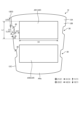
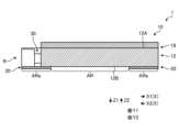
- FIG. 1 is a schematic top view of a vehicle glass unit according to the present embodiment.
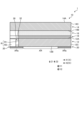
- FIG. 2 is a schematic cross-sectional view of the vehicle glass unit according to the present embodiment.
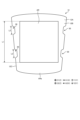
- FIG. 3 is a schematic diagram of the first glass plate.
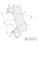
- FIG. 4 is a partial enlarged view of the cutout portion of the first glass plate.
- FIG. 5 is a schematic diagram showing another example of a vehicle glass.
- FIG. 6 is a schematic diagram showing another example of a vehicle glass.
- FIG. 7 is a schematic diagram showing another example of a vehicle glass.
- FIG. 8 is a schematic diagram showing another example of a vehicle glass.
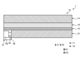
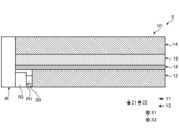
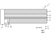
- FIG. 9 is a schematic cross-sectional view of a vehicle glass unit according to another embodiment.
- FIG. 10 is a schematic cross-sectional view of a vehicle glass unit according to another embodiment.
- FIG. 11 is a schematic cross-sectional view of a vehicle glass unit according to another embodiment.
- FIG. 1 is a schematic top view of the vehicle glass unit according to this embodiment
- FIG. 2 is a schematic cross-sectional view of the vehicle glass unit according to this embodiment.
- the vehicle glass unit 1 according to this embodiment has a vehicle glass 10 and an irradiation device R that irradiates light toward the vehicle glass 10.
- the vehicle glass unit 1 (vehicle glass 10) according to this embodiment is mounted on a vehicle and can be used, for example, as a vehicle window.
- the vehicle glass unit 1 (vehicle glass 10) may be mounted at any position of the vehicle and may be used, for example, as a roof glass, a windshield, a rear window, and a side window.
- the vehicle glass unit 1 (vehicle glass 10) is used as a roof glass provided on the roof of the vehicle.
- the vehicle glass 10 has a first glass plate 12, a second glass plate 14, an intermediate layer 16, a scattering layer 18, and a light-shielding layer 20.
- the direction perpendicular to the main surface of the vehicle glass 10 is the Z direction
- the direction toward one side of the Z direction is the Z1 direction
- the direction toward the other side of the Z direction is the Z2 direction.
- the vehicle glass 10 is laminated in the order of the second glass plate 14, the intermediate layer 16, the scattering layer 18, the first glass plate 12, and the light-shielding layer 20 toward the Z1 direction.
- the Z1 direction is the vehicle interior direction (direction toward the vehicle interior) and the Z2 direction is the vehicle exterior direction (direction toward the vehicle exterior).
- the direction perpendicular to the surface at the center position of the vehicle glass 10 may be the Z direction.
- one direction perpendicular to the Z direction is referred to as the X direction (first direction)
- the direction toward one side of the X direction is referred to as the X1 direction
- the direction toward the other side of the X direction is referred to as the X2 direction.
- the direction perpendicular to the Z direction and the X direction is referred to as the Y direction (second direction), the direction toward one side of the Y direction is referred to as the Y1 direction, and the direction toward the other side of the Y direction (opposite to the Y1 direction) is referred to as the Y2 direction.
- the Y direction is the front-rear direction of the vehicle and the X direction is the left-right direction of the vehicle.
- the relationship between the X direction and the Y direction and the direction of the vehicle is not limited thereto and may be any.
- the first glass plate 12 is a glass plate located inside the vehicle when the vehicle glass 10 is installed in the vehicle.
- the first glass plate 12 has a main surface 12A (first main surface) facing the Z2 direction, a main surface 12B (a second main surface opposite to the main surface 12A) facing the Z1 direction, and an end surface 12C connecting the main surface 12A and the main surface 12B.
- the main surfaces 12A and 12B may be called the third surface and the fourth surface of the vehicle glass 10, respectively.
- the end surface 12C is an end surface on the radial outer side of the first glass plate 12 when viewed from the Z direction, and can also be called a side surface of the first glass plate 12.
- the thickness of the first glass plate 12 is preferably 0.3 mm to 4.0 mm, more preferably 0.3 mm to 2.3 mm, more preferably 0.5 mm to 2.1 mm, and even more preferably 0.7 mm to 1.9 mm. Having a thickness within this range improves handling and prevents the mass from becoming too large, thereby suppressing a decrease in fuel efficiency of the vehicle. In addition, light is easily introduced into the glass plate, and the amount of light absorbed by the glass plate is not excessively large.
- the thickness of the first glass plate 12 refers to the length in the Z direction from the main surface 12A to the main surface 12B. For example, when the first glass plate 12 is curved, it may be the length in the Z direction from the center position of the main surface 12A to the center position of the main surface 12B.
- the first glass plate 12 may be curved. It is preferable that the first glass plate 12 is curved so as to be convex toward the Z2 direction. As shown in FIG. 3, in the example of this embodiment, the first glass plate 12 is curved so as to be convex toward the Z2 direction with the Y direction as the bending axis. However, the direction of the bending axis may be arbitrary. The bending axis here can be said to be the central axis of the circle of curvature of the first glass plate 12. The radius of curvature of the first glass sheet 12 when curved may be 100 mm or more and 10,000 mm or less. When the radius of curvature is within this range, the glass sheet 12 can be appropriately mounted on a vehicle.
- the radius of curvature of the first glass sheet 12 here refers to the radius of curvature of the bend with one direction (Y direction in the example of FIG. 3) as the bending axis.
- the first glass sheet 12 is not limited to being curved with only one direction as the bending axis, and may be a complex curved shape with multiple different directions (for example, two directions) as the bending axis.
- the radius of curvature corresponding to each bending axis is preferably within the above numerical range.
- the first glass sheet 12 is not limited to being curved, and may be flat.
- the first glass plate 12 may have any shape, but in this embodiment, the shape is such that the length in the X direction decreases as it approaches the Y2 direction.
- the first glass plate 12 is a trapezoidal flat plate whose length in the X direction decreases as it approaches the Y2 direction, curved with the Y direction as the bending axis.
- a cutout portion 30 is formed in the first glass plate 12.
- An irradiation device R is provided within the cutout portion 30. The cutout portion 30 and the irradiation device R will be described later.
- the first glass plate 12 may be made of any material, such as soda lime glass, borosilicate glass, or aluminosilicate glass.
- the first glass plate 12 may be tempered glass, and may be air-cooled tempered glass or chemically tempered glass.
- the vehicle glass unit has only one glass plate, it is preferable to use tempered glass, and it is particularly preferable to use air-cooled tempered glass.
- the multiple glass plates may include at least one of untempered glass and tempered glass.
- the second glass plate 14 is located in the Z2 direction from the first glass plate 12 and overlaps the first glass plate 12 when viewed from the Z direction. That is, the second glass plate 14 is a glass plate located on the vehicle exterior side when the vehicle glass 10 is installed in a vehicle.
- the second glass plate 14 has a main surface 14A facing the Z2 direction, a main surface 14B (main surface opposite to the main surface 14A) facing the Z1 direction, and an end surface 14C connecting the main surface 14A and the main surface 14B.
- the main surfaces 14A and 14B may be called the first surface and the second surface of the vehicle glass 10, respectively.
- the end surface 14C is an end surface on the radial outer side of the second glass plate 14 when viewed from the Z direction, and can also be called a side surface of the second glass plate 14.
- the thickness of the second glass plate 14 is preferably equal to or greater than the thickness of the first glass plate 12. However, the thickness of the second glass plate 14 may be smaller than the thickness of the first glass plate 12.
- the thickness of the second glass plate 14 is preferably 1.1 mm or more and 3.0 mm or less, more preferably 1.8 mm or more and 2.8 mm or less, even more preferably 1.8 mm or more and 2.6 mm or less, even more preferably 1.8 mm or more and 2.2 mm or less, and even more preferably 1.8 mm or more and 2.0 mm or less.
- the thickness of the second glass plate 14 refers to the length in the Z direction from the main surface 14A to the main surface 14B.
- it may be the length in the Z direction from the center position of the main surface 14A to the center position of the main surface 14B.
- Other features of the second glass plate 14 are the same as those of the first glass plate 12 described above, and therefore will not be described here. Note that the radius of curvature of the second glass plate 14 and the radius of curvature of the first glass plate 12 may be the same or different.
- the vehicle glass 10 is a laminated glass having two glass plates, a first glass plate 12 and a second glass plate 14, but the number of glass plates is not limited to this and may be three or more. As described later, the vehicle glass 10 may also be a single-pane glass having only the first glass plate 12 as a glass plate.
- the intermediate layer 16 is located between the first glass plate 12 and the second glass plate 14 in the Z direction.
- the intermediate layer 16 is an adhesive layer that bonds the first glass plate 12 and the second glass plate 14. Any material may be used for the intermediate layer 16, but a thermoplastic resin or a curable resin is preferable, and a thermoplastic resin is particularly preferable.
- thermoplastic resin polyvinyl butyral (PVB) resin, ethylene vinyl acetate copolymer (EVA) resin, polyurethane resin, ionomer resin, cycloolefin polymer, etc.
- the thermoplastic resin is selected in consideration of the balance of various performances such as glass transition point, transparency, weather resistance, adhesive strength, penetration resistance, impact energy absorption, moisture resistance, heat insulation, etc. Considering the balance of the above-mentioned various performances, the thermoplastic resin is preferably PVB resin, EVA resin, or polyurethane resin.
- the curable resin any resin that is cured by heat, light (ultraviolet rays), etc. may be used, for example, acrylic or silicone resin.
- the intermediate layer 16 is not an essential component. For example, in a configuration in which only the first glass plate 12 is provided as a glass plate, the intermediate layer 16 does not need to be provided.
- the scattering layer 18 is a layer for scattering light incident at least through the cutout portion 30 into the first glass plate 12.
- the scattering layer 18 is configured so that the light incident on the scattering layer 18 is scattered at least in the Z1 direction.
- the scattering layer 18 is a layer provided at a position overlapping the main surfaces (main surfaces 12A and 12B) of the first glass plate 12 when viewed from the Z direction (in a plan view).
- the scattering layer 18 is provided at a position overlapping the main surfaces of the first glass plate 12 and the second glass plate 14 when viewed from the Z direction. As shown in Fig.
- the scattering layer 18 is provided between the main surface 12A of the first glass plate 12 and the intermediate layer 16.
- the scattering layer 18 may be provided on the main surface 12B of the first glass plate 12 (in the Z1 direction from the main surface 12B), may be provided inside the intermediate layer 16, may be provided between the intermediate layer 16 and the main surface 14B of the second glass plate 14, or may be provided on the main surface 14B of the second glass plate 14 (in the Z1 direction from the main surface 14B).
- the material and method of forming the scattering layer 18 are not particularly limited.
- the scattering layer 18 may be formed by holding fine particles on the surface or inside of a resin sheet such as polyethylene terephthalate (PET), polyethylene (PE), polycarbonate (PC), polyurethane (PU), or silicone.
- the scattering layer 18 may also be formed by holding fine particles on the surface or inside of a thermoplastic resin or a curable resin that constitutes the intermediate layer 16.
- Fine particles are, for example, particles with a volume average particle size exceeding 0.1 ⁇ m, preferably not exceeding 10 ⁇ m.
- the volume average particle size is determined by a particle size distribution measuring device using a laser diffraction scattering method (for example, "UPA-EX150” manufactured by Nikkiso Co., Ltd.).
- the scattering layer 18 may also be formed by subjecting the surface of the glass plate to surface processing such as sandblasting or etching.
- the scattering layer 18 may also be formed by applying a white pigment or the like to the surface of the glass plate using screen printing, inkjet printing, or the like, and drying the applied material.
- the scattering layer 18 may also be formed by applying a paste containing a white pigment or the like and a fusible glass frit to the glass plate and baking the paste.
- the light-shielding layer 20 is a layer that blocks visible light.
- the visible light transmittance of the light-shielding layer 20 is usually 5% or less, preferably 3% or less, and may be substantially 0%.
- the light-shielding layer 20 is a layer provided at a position overlapping a partial region of the main surface (main surface 12A and main surface 12B) of the first glass plate 12 when viewed from the Z direction.
- the light-shielding layer 20 is provided at a position overlapping a partial region of the main surface of the first glass plate 12 and a partial region of the main surface of the second glass plate 14 when viewed from the Z direction.
- the light-shielding layer 20 is provided on the main surface 12B of the first glass plate 12 (in the Z1 direction from the main surface 12B).
- the light-shielding layer 20 when viewed from the Z direction (in a plan view), the light-shielding layer 20 is provided with a predetermined width on the peripheral portion of the first glass plate 12.
- the position at which the light-shielding layer 20 is provided is not limited thereto and may be any position.
- the light-shielding layer 20 may be provided on the main surface 14B of the second glass plate 14 (in the Z1 direction from the main surface 14B), or may be provided on both the main surface 12B of the first glass plate 12 and the main surface 14B of the second glass plate 14.
- the material of the light-shielding layer 20 may be any material.
- a ceramic light-shielding layer or a light-shielding film can be used as the light-shielding layer 20.
- a ceramic layer made of a conventionally known material such as a black ceramic layer can be used as the ceramic light-shielding layer.
- a light-shielding polyethylene terephthalate (PET) film, a light-shielding polyethylene naphthalate (PEN) film, a light-shielding polymethyl methacrylate (PMMA) film, or the like can be used as the light-shielding film.
- PET light-shielding polyethylene terephthalate
- PEN light-shielding polyethylene naphthalate
- PMMA light-shielding polymethyl methacrylate
- the light-shielding layer 20 is not an essential component. In other words, the vehicle glass unit 1 does not need to have the light-shielding
- the vehicle glass 10 is formed with a transmission area AR.
- the transmission area AR refers to an area that transmits light scattered by the scattering layer 18 in the entire area of the main surface of the vehicle glass 10.
- the area in which the scattering layer 18 is provided when viewed from the Z direction is the transmission area AR. That is, the light incident from the irradiation device R into the first glass plate 12 is transmitted or blocked without being scattered by the scattering layer 18 in the area in which the scattering layer 18 is not provided.
- the light incident from the irradiation device R into the first glass plate 12 is scattered by the scattering layer 18 and is guided in the Z1 direction through the transmission area AR in which the scattering layer 18 is provided.
- the transmission region AR can be said to be a region where the scattering layer 18 is provided and where the light-shielding layer 20 is not provided, when viewed from the Z direction. That is, the light incident on the first glass plate 12 from the irradiation device R is blocked in the region where the light-shielding layer 20 is provided and is not transmitted in the Z1 direction. On the other hand, the light scattered by the scattering layer 18 is not blocked by the light-shielding layer 20 in the region where the light-shielding layer 20 is not provided and transmits in the Z1 direction.
- the transmissive region AR has a rectangular shape when viewed from the Z direction.
- two transmissive regions AR1 and AR2 aligned in the Y direction are formed as the transmissive region AR.
- the shape of the transmissive region AR is not limited thereto and may be any shape, and the number and alignment direction of the transmissive regions AR may also be any shape.
- the area other than the transmissive area AR in the entire area of the main surface of the vehicle glass 10 will be referred to as a non-transmissive area ARa as appropriate.
- the non-transmissive area ARa can be said to be an area that satisfies at least one of the following when viewed from the Z direction: the scattering layer 18 is not provided, and the light-shielding layer 20 is provided.
- the light-shielding layer 20 in the non-transmissive area ARa includes at least a portion that is disposed further in the Z1 direction than the scattering layer 18.
- the length of the transmission area AR in the Y direction is defined as length L1.
- the length L1 is preferably 50 mm or more and 1500 mm or less, preferably 150 mm or more and 1000 mm or less, and more preferably 300 mm or more and 800 mm or less.
- the length of the transmission area AR in the X direction is defined as length D1.
- the length D1 is preferably 500 mm or more and 1200 mm or less, preferably 600 mm or more and 1000 mm or less, and more preferably 700 mm or more and 900 mm or less.
- the length L1 may refer to the length of a line connecting an end of the transmissive region AR in the Y1 direction and an end of the transmissive region AR in the Y2 direction along the main surface of the first glass plate 12.
- the length D1 may refer to the length of a line connecting an end of the transmissive region AR in the X1 direction and an end of the transmissive region AR in the X2 direction along the main surface of the first glass plate 12.
- the vehicle glass 10 has the above-mentioned configuration. However, the vehicle glass 10 may have layers other than those mentioned above.
- the vehicle glass 10 may be provided with a low-emissivity (Low-E) layer or an infrared reflective/absorbent layer at a position overlapping with the main surface of the first glass plate 12 when viewed from the Z direction.
- the low-emissivity layer is a layer that reduces radiation, and may be, for example, a film containing a metal oxide such as tin oxide or a metal such as silver.
- the emissivity of the low-emissivity layer is, for example, less than 0.3.
- the low-emissivity layer may be provided, for example, on the main surface 12B of the first glass plate 12 (in the Z1 direction from the main surface 12B).
- the infrared reflective/absorbent layer may be provided, for example, on the main surface 14B of the second glass plate 14 (in the Z1 direction from the main surface 14B).
- the cutout portion 30 formed in the first glass plate 12 will be described.
- the cutout portion 30 is a cutout formed in the end surface 12C of the first glass plate 12.
- the cutout portion 30 penetrates from the main surface 12A to the main surface 12B of the first glass plate 12.
- the cutout portion 30 is recessed toward the inside (radial inner side) of the first glass plate 12, and in this embodiment, is recessed toward the X direction.
- the cutout portion 30 is formed in at least one of the end surface 12C in the X2 direction of the first glass plate 12 and the end surface 12C in the X1 direction of the first glass plate 12.
- the cutout portion 30 provided in the end surface 12C in the X2 direction is recessed toward the X1 direction, and the cutout portion 30 provided in the end surface 12C in the X1 direction is recessed toward the X2 direction.
- the notch 30 is preferably formed on both the end face 12C of the first glass plate 12 in the X2 direction and the end face 12C of the first glass plate 12 in the X1 direction.
- the cutout portion 30 is preferably formed at a position overlapping the transmission region AR when viewed from the X direction.
- the cutout portion 30 is preferably located in the X direction of the transmission region AR when viewed from the Z direction. That is, for example, the cutout portion 30 provided on the end face 12C in the X2 direction is located in the X2 direction of the transmission region AR, and the cutout portion 30 provided on the end face 12C in the X1 direction is located in the X1 direction of the transmission region AR.
- only one cutout portion 30 is formed on one side of one transmission region AR in the X direction.
- one cutout portion 30 located in the X1 direction and one cutout portion 30 located in the X2 direction are formed for one transmission region AR.
- one cutout portion 30 is formed in each of the X1 direction and the X2 direction of the transmission regions AR1 and AR2.
- the number of cutout portions 30 for the transmission region AR may be arbitrary, and a plurality of cutout portions 30 aligned in the Y direction may be formed on one or both sides of the X direction for one transmission region AR.
- FIG. 4 is a partial enlarged view of the cutout portion of the first glass plate.
- the shape and size of the cutout portion 30 may be arbitrary, but as shown in FIG. 4, in this embodiment, the cutout portion 30 has a bottom surface portion 32, a first side surface portion 34, and a second side surface portion 36.
- the cutout portion 30 formed on the end surface 12C in the X2 direction will be used as an example.
- the cutout portion 30 formed on the end surface 12C in the X1 direction is similar to the cutout portion 30 formed on the end surface 12C in the X2 direction except that the X1 and X2 directions are reversed, so a description of the cutout portion 30 will be omitted.
- the bottom surface portion 32 of the cutout portion 30 is a surface including the portion that is most recessed by the cutout portion 30, and can be said to be the surface of the region in which the cutout portion 30 is formed among the entire region of the edge surface 12C of the first glass plate 12.
- the first side surface portion 34 is a side surface located in the Y1 direction of the bottom surface portion 32, and connects the bottom surface portion 32 and the edge surface 12C.
- the second side surface portion 36 is a side surface located in the Y2 direction of the bottom surface portion 32, and connects the bottom surface portion 32 and the edge surface 12C.
- the cutout portion 30 is a recess formed by the bottom surface portion 32, the first side surface portion 34, and the second side surface portion 36.
- connection portion 34A is preferably a curved surface (curved shape) recessed inward when viewed from the Z direction.
- connection portion 34A is preferably a curved surface recessed toward the X1 direction.
- connection portion 34B is preferably a curved surface protruding outward when viewed from the Z direction.
- connection portion 34B is preferably a curved surface protruding toward the X2 direction.
- connection portion 36A is a curved surface that is recessed inward when viewed from the Z direction.
- connection portion 36B is a curved surface that protrudes outward when viewed from the Z direction.
- connection portion 36B is a curved surface that protrudes toward the X2 direction.
- the radius of curvature of the bottom surface portion 32 with the Z direction as the bending axis is preferably 100 mm or more, more preferably 200 mm or more and 10,000 mm or less, and even more preferably 300 mm or more and 8,000 mm or less.
- the radius of curvature of the bottom surface portion 32 with the Z direction as the bending axis is preferably equal to or greater than the radius of curvature of the connection points 34A, 34B, 36A, and 36B with the Z direction as the bending axis.
- the depth (length in the X direction) of the cutout portion 30 relative to the width (length in the Y direction) of the cutout portion 30 can be kept small, which is preferable from the standpoint of strength and manufacturing process.
- the radius of curvature of the connection points 34A, 34B, 36A, and 36B, with the Z direction as the bending axis is preferably 30 mm or more and 1200 mm or less, more preferably 50 mm or more and 1000 mm or less, and even more preferably 80 mm or more and 800 mm or less.
- the radius of curvature of the connection points 34A, 34B, 36A, and 36B can be made small enough to appropriately capture light from the irradiation device R, while suppressing cracks originating from the connection points 34A, 34B, 36A, and 36B due to the radius of curvature being too small.
- the length L2 which is the length (width) in the Y direction of the cutout portion 30, is preferably 50 mm or more and 800 mm or less, more preferably 100 mm or more and 500 mm or less, and even more preferably 150 mm or more and 300 mm or less.
- the length L2 800 mm or less it is possible to appropriately emit light without increasing the number of irradiation units R1 included in the irradiation device R, which will be described later, and also to suppress a decrease in the strength of the first glass plate 12.
- the length L2 may be the distance from the position P1 at the intersection of the line A1 and the line A2 to the position P2 at the intersection of the line A1 and the line A3 as viewed from the Z direction.
- the line A1 is an approximation line of the section of the end face 12C other than the section where the notch portion 30 is formed as viewed from the Z direction.
- the line A1 is obtained by approximating the profile of the end face 12C in the section where the notch portion 30 is not formed as viewed from the Z direction with a straight line.
- the line A2 is an approximation line of the first side portion 34 as viewed from the Z direction.
- the line A2 is obtained by approximating the profile of the first side portion 34 in the section between a position 5 mm away from the center position of the first side portion 34 in the Y direction in the Y1 direction and a position 5 mm away from the center position as viewed from the Z direction in the Y direction with a straight line.
- the line A3 is an approximation line of the second side portion 36 as viewed from the Z direction.
- Line A3 is obtained by approximating the profile of the second side portion 36 as viewed from the Z direction in the section between a position 5 mm away in the Y1 direction from the center position of the second side portion 36 in the Y direction and a position 5 mm away in the Y2 direction from the center position, as viewed from the Z direction.
- the length D2 which is the length (depth) of the cutout portion 30 in the X direction, is preferably 3 mm to 200 mm, more preferably 5 mm to 150 mm, and even more preferably 10 mm to 100 mm.
- the irradiation device R can be appropriately positioned within the cutout portion 30 to appropriately capture light, suppress a decrease in the strength of the first glass plate 12, and also enable the manufacturing process to be performed appropriately.
- the length D2 may be the distance between the most recessed position of the bottom surface portion 32 and the line A1 when viewed from the Z direction.
- the ratio (L2/D2) of the length L2 of the cutout portion 30 to the length D2 is preferably 0.025 or more and 260 or less, more preferably 0.65 or more and 100 or less, even more preferably 1.0 or more and 50 or less, and even more preferably 1.5 or more and 30 or less. Having a ratio within this range allows light to be appropriately taken in, suppresses a decrease in the strength of the first glass plate 12, and also allows the manufacturing process to be carried out appropriately.
- the opening angle ⁇ of the cutout portion 30 when viewed from the Z direction is preferably 0° to 120°, more preferably 5° to 90°, and even more preferably 10° to 45°.
- the opening angle ⁇ may be the angle between the line A2 and the line A3 when viewed from the Z direction.
- the maximum valley depth Rv of the bottom surface portion 32 as defined in the 2013 JIS B0601 "Geometric Product Specifications (GPS) - Surface Texture: Profile Curve Method - Terms, Definitions and Surface Texture Parameters” is preferably smaller (smoother) than the maximum valley depth Rv at the portion of the end face 12C where the notch portion 30 is not formed.
- the maximum valley depth Rv of the bottom surface portion 32 as defined in the 2013 JIS B0601 is preferably 0.6 ⁇ m or less, and more preferably 0.2 ⁇ m or less.
- the total length L2A is the sum of the lengths L2 of the cutout portions 30 located on one side in the X direction for one transmission region AR. That is, in the example of Fig. 3, the number of cutout portions 30 located on one side in the X direction (the X2 direction in this example) for one transmission region AR is one, so the total length L2A can be said to be the length L2 of that cutout portion 30. On the other hand, for example, if there are a plurality of cutout portions 30 located on one side in the X direction (the X2 direction in this example) for one transmission region AR, the total length L2A refers to the sum of the lengths L2 of those cutout portions 30.
- the ratio (L2A/L1) of the total length L2A of the cutout portion 30 located on one side of the X direction with respect to the length L1 of the transmission region AR is preferably 1/8 or more, more preferably 1/2 or more, and even more preferably 2/3 or more.
- the ratio (L2A/L1) is preferably 1.0 or less, more preferably 5/6 or less, and even more preferably 4/5 or less. That is, the ratio (L2A/L1) is preferably 1/8 or more and 1.0 or less, more preferably 1/2 or more and 5/6 or less, and even more preferably 2/3 or more and 4/5 or less.
- the ratio (L2A/L1) By setting the ratio (L2A/L1) to 1/8 or more, it is possible to appropriately take in the light from the irradiation device R into the first glass plate 12, and to make the intensity of the light scattered by the scattering layer 18 and led out in the Z1 direction closer to uniform. Furthermore, by setting the ratio (L2A/L1) to 1.0 or less, it becomes possible to appropriately emit light without increasing the number of irradiation sections R1 (described later) included in the irradiation device R, and also makes it possible to suppress a decrease in the strength of the first glass plate 12.
- the distance ⁇ D between the transmission area AR and the cutout portion 30 located on one side of the transmission area AR in the X direction is preferably 200 mm or less, more preferably 5 mm or more and 100 mm or less, and even more preferably 10 mm or more and 30 mm or less.
- the intensity of the light emitted from the transmission area AR in the Z1 direction can be made closer to uniform.
- the first glass plate 12 has a corner 12ED.
- the corner 12ED is a boundary between one end face 12C in the X direction and one end face 12C in the Y direction.
- the distance ⁇ ED between the cutout 30 and the corner 12ED closest to the cutout 30 is preferably 30 mm or more, more preferably 50 mm or more and 500 mm or less, and even more preferably 80 mm or more and 300 mm or less.
- the cutout portion 30 overlaps with the light-shielding layer 20 when viewed from the Z direction.
- the cutout portion 30 overlaps with the light-shielding layer 20 when viewed from the Z direction.
- the irradiation device R is a device that irradiates light (visible light) into the first glass plate 12. As shown in FIG. 1, the irradiation device R has an irradiation section R1 and a substrate R2.
- the irradiation section R1 is a part of the irradiation device R that emits light, and in this embodiment, it is a light source such as an LED that emits light.
- the substrate R2 is a substrate connected to the irradiation section R1.
- a plurality of irradiation sections R1 are provided so as to be aligned in the Y direction, and it is preferable that the distance between adjacent irradiation sections R1 in the Y direction is uniform.
- the number of irradiation sections R1 is preferably 3 to 50, more preferably 5 to 30, and even more preferably 10 to 20. By the number of irradiation sections R1 being within this range, the intensity of the light transmitted from the transmission area AR1 in the Z1 direction can be sufficiently maintained.
- the number of irradiation sections R1 and the direction in which they are aligned are not limited to this and may be arbitrary.
- the irradiation unit R1 is not limited to being a light source such as an LED.
- the irradiation device R may be configured to include a light source, a light guide through which light from the light source passes, and an outlet formed in the light guide and capable of transmitting light.
- the outlet formed in the light guide corresponds to the irradiation unit R1. That is, in this configuration, the light irradiated from the light source into the light guide is emitted from the irradiation unit R1, which is the outlet.
- the irradiation device R is at least partially mounted within the cutout portion 30. Specifically, it is preferable that the irradiation device R is mounted within the cutout portion 30 so that at least the portion that emits light of the irradiation section R1 faces the bottom surface portion 32 of the cutout portion 30. When multiple cutout portions 30 are formed, it is preferable that the irradiation device R is at least partially mounted within each of the cutout portions 30.
- the vehicle glass unit 1 is configured as described above.
- the light emitted from the irradiation unit R1 of the irradiation device R enters the first glass plate 12 from the bottom surface 32 of the cutout portion 30 facing the irradiation device R.
- the light that enters the first glass plate 12 travels in the X direction while being reflected by the main surfaces 12A and 12B of the first glass plate 12.
- a part of the light that enters the first glass plate 12 passes through the main surface 12A and is scattered by the scattering layer 18, travels in the Z1 direction, and is emitted in the Z1 direction from the transmission area AR of the main surface 12B.
- the light scattered by the scattering layer 18 passes through almost the entire transmission area AR in the Z1 direction (inside the vehicle) and is visible inside the vehicle.
- the vehicle glass 10 has a first glass plate 12 and a scattering layer 18, and a cutout portion 30 is formed on the end surface 12C of the first glass plate 12. Therefore, by attaching the irradiation device R to the cutout portion 30, light from the irradiation device R can be taken into the first glass plate 12 from the cutout portion 30, so that the light can be appropriately taken into the first glass plate 12.
- the irradiation device R can be arranged in the cutout portion 30, it is possible to prevent the irradiation device R from protruding from the vehicle glass 10, and it is possible to easily install it in the vehicle.
- the cutout portion 30 for mounting the irradiation device R is formed in advance, so the size of the cutout portion 30 can be adjusted to prevent a decrease in strength.
- FIG. 5 is a schematic diagram showing another example of vehicle glass.
- the distance ⁇ D between the transparent region AR and the cutout 30 in the X direction of the transparent region AR may be uniform. More specifically, when multiple cutouts 30 arranged in the Y direction are formed on one side of the X direction, the distance ⁇ D between each cutout 30 and the transparent region AR may be uniform.
- the transparent regions AR1 and AR2 arranged in the Y direction are formed, the distance ⁇ D between the transparent region AR1 and its cutout 30 in the X1 direction and the distance ⁇ D between the transparent region AR2 and its cutout 30 in the X1 direction are uniform.
- the distance ⁇ D between the transparent region AR1 and its cutout 30 in the X2 direction and the distance ⁇ D between the transparent region AR2 and its cutout 30 in the X2 direction are uniform.
- the length of the first glass plate 12 in the X direction increases in the Y1 direction, so the area of the cutout portion 30 located in the X direction of the transmissive region AR1 is larger than the area of the cutout portion 30 located in the X direction of the transmissive region AR2 that is closer to the Y2 direction than the transmissive region AR1.
- the distance ⁇ D of each cutout portion 30 may be uniform.
- the distance ⁇ D being uniform does not necessarily mean that the distances ⁇ D are exactly the same value, and may include a general error (for example, an error of about 3 mm or less).
- the distance from the irradiation device R to the transmission area AR can be made uniform, so that the intensity of the light transmitted from the transmission area AR can be made closer to uniform.
- the method of making the intensity of the light transmitted from the over-region AR closer to uniform is not limited to making the distance ⁇ D uniform.
- the intensity of the light from the irradiation device R mounted on the cutout 30 may be set higher as the distance ⁇ D from the cutout 30 to the transmission region AR becomes longer. This allows the intensity of the light at the position where the distance ⁇ D is long and the light is easily attenuated to be increased in advance, making it possible to make the intensity of the light transmitted from the transmission region AR closer to uniform.
- FIG. 6 is a schematic diagram showing another example of a vehicle glass.
- the region between the transmission region AR and the cutout portion 30 located in the X direction relative to the transmission region AR was a non-transmission region ARa in which the light-shielding layer 20 was provided.
- the region between the transmission region AR and the cutout portion 30 located in the X direction relative to the transmission region AR may be a non-light-shielding region ARB in which the light-shielding layer 20 is not provided. That is, when viewed from the Z direction, the light-shielding layer 20 may not be provided in the region between the transmission region AR and the cutout portion 30.
- the scattering layer 18 may or may not be formed in the non-light-shielding region ARB between the transmission region AR and the cutout portion 30.
- FIG. 7 is a schematic diagram showing another example of vehicle glass.
- the vehicle glass 10 may have one transmissive area AR.
- two cutout portions 30 aligned in the Y direction are formed in each of the X1 and X2 directions of the transmissive area AR.
- the number of cutout portions 30 formed in the X1 and X2 directions of the transmissive area AR may be any number.
- FIG. 8 is a schematic diagram showing another example of vehicle glass.
- the vehicle glass 10 is a laminated glass having a first glass plate 12 and a second glass plate 14.
- the vehicle glass 10 may be a single-pane glass having a first glass plate 12, which is a single glass plate.
- the vehicle glass 10 may have the first glass plate 12, a scattering layer 18, and a light-shielding layer 20.
- the scattering layer 18 is provided on the main surface 12A of the first glass plate 12, but is not limited thereto, and may be provided on the main surface 12B of the first glass plate 12, for example.
- FIG. 9 to 11 are schematic cross-sectional views of vehicle glass units according to other examples.
- the entire irradiation device R is disposed within the cutout portion 30 of the first glass plate 12.
- the present invention is not limited to this. Only a part of the irradiation device R may be located within the cutout portion 30, and the other part may protrude from the cutout portion 30.
- the irradiation device R may be provided from within the cutout portion 30 to a position protruding from within the cutout portion 30 in the Z direction (Z1 direction in this example).
- the irradiation device R may be provided from within the cutout portion 30 to a position protruding from within the cutout portion 30 in the Y direction (Y2 direction in this example).
- the portion of the irradiation device R protruding from within the cutout portion 30 in the Y direction may have any shape.
- the protruding portion may extend in the Z2 direction to a position facing the end face of the scattering layer 18 in the Y direction, a position facing the end face of the intermediate layer 16 in the Y direction, and a position facing the end face of the second glass plate 14 in the Y direction, as shown in FIG.
- the irradiation device R may protrude from the inside of the cutout portion 30 in both the Y direction and the Z direction. In this manner, when the irradiation device R protrudes from within the cutout portion 30, it is preferable that the irradiation section R1 of the irradiation device R is located within the cutout portion 30, and a portion of the irradiation device R other than the irradiation section R1 protrudes from the cutout portion 30.
- the portion of the irradiation device R other than the irradiation section R1 may be, for example, a housing that houses the irradiation section R1.
- the vehicle glass 10 has a first glass plate 12 including a main surface including a main surface 12A (first main surface) and a main surface 12B (second main surface) opposite to the main surface 12A, and an end surface 12C connecting the main surface 12A and the main surface 12B, and a scattering layer 18 overlapping the main surface of the first glass plate 12 in a plan view.
- the end surface 12C of the first glass plate 12 has a cutout portion 30 formed therein that is recessed inward in a plan view and penetrates from the main surface 12A to the main surface 12B, and the scattering layer 18 scatters light that enters the first glass plate 12 from the cutout portion 30.
- the vehicle glass 10 of the present disclosure can have an irradiation device R attached to the cutout portion 30 so that light from the irradiation device R can be taken in through the cutout portion 30 into the first glass plate 12, thereby enabling the light to be appropriately taken in into the first glass plate 12.
- the vehicle glass 10 according to the second aspect of the present disclosure is the vehicle glass 10 according to the first aspect, and when the direction perpendicular to the Z direction (thickness direction of the first glass plate 12) is the X direction (first direction) and the direction perpendicular to the Z direction and the X direction is the Y direction (second direction), the cutout portion 30 is recessed toward the X direction and overlaps with the transmission area AR that transmits the light scattered by the scattering layer 18 when viewed from the X direction.
- the ratio (L2A/L1) of the total length L2A to the length L1 is 1/8 or more.
- the ratio of the total length L2A to the length L1 is within this range, it is possible to appropriately take in the light from the irradiation device R into the first glass plate 12 and make the light scattered by the scattering layer 18 and led out in the Z1 direction closer to uniform.
- the vehicle glass 10 according to the third aspect of the present disclosure is the vehicle glass 10 according to the second aspect, and preferably has a ratio (L2A/L1) of the total length L2A to the length L1 of 1.0 or less.
- the ratio is in this range, it is possible to appropriately emit light without increasing the number of irradiation sections R1 included in the irradiation device R, and also to suppress a decrease in the strength of the first glass plate 12.
- the vehicle glass 10 according to the fourth aspect of the present disclosure is the vehicle glass 10 according to any one of the first to third aspects, and the length D2 of the cutout portion 30 in the X direction is preferably 3 mm or more and 200 mm or less.
- the irradiation device R can be appropriately positioned within the cutout portion 30 to appropriately capture light, suppress a decrease in the strength of the first glass plate 12, and also allow the manufacturing process to be performed appropriately.
- the vehicle glass 10 according to the fifth aspect of the present disclosure is the vehicle glass 10 according to any one of the first to fourth aspects, and it is preferable that the length L2 of the cutout portion 30 in the Y direction is 50 mm or more and 800 mm or less. By setting the length L2 within this range, it can be appropriately incorporated into the first glass plate 12.
- the vehicle glass 10 according to the sixth aspect of the present disclosure is the vehicle glass 10 according to any one of the first to fifth aspects, and the cutout portion 30 is preferably recessed in the X direction.
- the cutout portion 30 preferably has a bottom surface portion 32 which is the surface of the end surface 12C on which the cutout portion 30 is formed, a first side surface portion 34 located on one side of the bottom surface portion 32 in the Y direction and connecting the bottom surface portion 32 to the end surface 12C, and a second side surface portion 36 located on the other side of the bottom surface portion 32 in the Y direction and connecting the bottom surface portion 32 to the end surface 12C.
- the vehicle glass 10 according to the seventh aspect of the present disclosure is the vehicle glass 10 according to the sixth aspect, and in plan view, the radius of curvature of the bottom surface 32 is preferably 100 mm or more.
- the radius of curvature of the bottom surface 32 is preferably 100 mm or more.
- the vehicle glass 10 according to the eighth aspect of the present disclosure is the vehicle glass 10 according to the sixth or seventh aspect, and it is preferable that the connection point 34A between the first side portion 34 and the bottom surface portion 32 and the connection point 36A between the second side portion 36 and the bottom surface portion 32 are concave curved surfaces in a plan view, and the connection point 34B between the first side portion 34 and the end surface 12C and the connection point 36B between the second side portion 36 and the end surface 12C are convex curved surfaces in a plan view.
- the vehicle glass 10 according to the ninth aspect of the present disclosure is the vehicle glass 10 according to the eighth aspect, and preferably has a radius of curvature of the connection points 34A, 34B, 36A, and 36B of 30 mm or more and 1200 mm or less.
- a radius of curvature of the connection points 34A, 34B, 36A, and 36B of 30 mm or more and 1200 mm or less.
- the vehicle glass 10 according to the tenth aspect of the present disclosure is the vehicle glass 10 according to any one of the first to ninth aspects, and the bottom surface 32 of the cutout portion 30 preferably has a maximum valley depth Rv of 0.6 ⁇ m or less as specified in JIS B0601 of 2013. By setting the surface roughness of the bottom surface 32 within this range, it is possible to appropriately capture light from the irradiation device R.
- the vehicle glass 10 according to the eleventh aspect of the present disclosure is the vehicle glass 10 according to any one of the first to tenth aspects, in which the first glass plate 12 has a corner 12ED in a plan view, and the distance ⁇ ED between the cutout 30 and the corner 12ED is preferably 30 mm or more. By setting the distance ⁇ ED within this range, the cutout 30 is sufficiently separated from the corner 12ED, and cracks originating from the cutout 30 can be appropriately suppressed.
- the vehicle glass 10 according to the twelfth aspect of the present disclosure is the vehicle glass 10 according to any one of the first to eleventh aspects, and it is preferable that the distance ⁇ D between the bottom surface portion 32 of the cutout portion 30 and the transmission area AR is 200 mm or less. By setting the distance ⁇ D within this range, the intensity of the light emitted from the transmission area AR in the Z1 direction can be made closer to uniform.
- the vehicle glass 10 according to the thirteenth aspect of the present disclosure is the vehicle glass 10 according to any one of the first to twelfth aspects, and preferably further comprises a second glass plate 14 that overlaps with the first glass plate 12 in a plan view, and an intermediate layer 16 provided between the first glass plate 12 and the second glass plate 14. By forming it into a laminated glass in this way, it can be appropriately used as vehicle glass.
- the vehicle glass 10 according to the fourteenth aspect of the present disclosure is the vehicle glass 10 according to any one of the first to thirteenth aspects, and is preferably installed on the ceiling of a vehicle.
- the vehicle glass 10 By using the vehicle glass 10 as a roof glass, it is possible to appropriately emit light toward the interior of the vehicle.
- the vehicle glass unit 1 according to the fifteenth aspect of the present disclosure includes a vehicle glass 10 according to any one of the first to fourteenth aspects, and an irradiation device R that is attached to the cutout portion 30 and irradiates light toward the bottom surface portion 32 of the cutout portion 30. According to the present disclosure, light from the irradiation device R can be taken into the first glass plate 12 from the cutout portion 30, so that the light can be appropriately taken into the first glass plate 12.
- Table 1 shows vehicle glass of each example and the evaluation results thereof.
- Example 1 In Example 1, a simulation model of a glass plate having a length of 500 mm in the X direction, a length of 800 mm in the Y direction, and a thickness of 2 mm was prepared, and one notch was formed on the end face of the glass plate in the X direction, and a part of the glass plate was made into a transmission area.
- the length (width) L1 of the transmission area in the Y direction, the length (width) L2 of the notch in the Y direction, the length (depth) D2 of the notch in the X direction, and the distance ⁇ D from the notch to the transmission area were as shown in Table 1.
- the ratio (L2/L1) of the length L2 to the length L1 was as shown in Table 1.
- irradiation units were arranged in the Y direction within the notch.
- the number of arranged irradiation units is shown in Table 1.
- An optical simulation (manufactured by AGC) was performed using the above-described simulation model. In the optical simulation, light was irradiated from each irradiation unit, and the intensity of light transmitted in the Z2 direction from the transmission region was analyzed.
- Example 2 In Example 2, except that no cutout was formed and an irradiation unit was disposed on the end face of the glass plate, an optical simulation was performed in the same manner as in Example 1. Note that, since no cutout was formed in Example 2, the distance ⁇ D from the cutout to the transmission region is the distance from the end face of the glass plate in the X direction to the transmission region.
- Example 1 which is an embodiment in which a cutout portion is provided, was evaluated as A, indicating that light can be appropriately taken in.
- Example 2 which is a comparative example in which a cutout portion is not provided, was evaluated as B, indicating that light cannot be appropriately taken in.
- the embodiments of the present invention have been described above, the embodiments are not limited to the contents of these embodiments.
- the aforementioned components include those that a person skilled in the art would easily imagine, those that are substantially the same, and those that are within the scope of what is known as equivalence.
- the aforementioned components can be combined as appropriate.
- various omissions, substitutions, or modifications of the components can be made without departing from the spirit of the aforementioned embodiments.
- Vehicle glass unit 10 Vehicle glass 12 First glass plate 12A, 12B Main surface 12C End surface 14 Second glass plate 16 Intermediate layer 18 Scattering layer 20 Light-shielding layer 30 Notch portion AR Transmission region R Irradiation device
Landscapes
- Engineering & Computer Science (AREA)
- Mechanical Engineering (AREA)
- Surface Treatment Of Glass (AREA)
Abstract
Dans la présente invention, de la lumière est introduite de manière appropriée dans une plaque de verre. Une vitre de véhicule (10) comprend : une première plaque de verre (12) qui comprend des surfaces principales comprenant une première surface principale et une seconde surface principale, qui est sur le côté opposé à la première surface principale, et une surface d'extrémité (12C) reliant la première surface principale et la seconde surface principale l'une à l'autre ; et une couche de diffusion (18) qui chevauche les surfaces principales de la première plaque de verre (12) dans une vue en plan. Dans la surface d'extrémité (12C) de la première plaque de verre (12), une partie découpée (30) qui est évidée vers l'intérieur dans la vue en plan et passe de la première surface principale à la seconde surface principale est formée et la couche de diffusion (18) diffuse la lumière entrant dans la première plaque de verre (12) à partir de la partie découpée (30).
Priority Applications (2)
| Application Number | Priority Date | Filing Date | Title |
|---|---|---|---|
| JP2025506925A JPWO2024190861A1 (fr) | 2023-03-14 | 2024-03-14 | |
| CN202480013129.8A CN120712192A (zh) | 2023-03-14 | 2024-03-14 | 车辆用玻璃及车辆用玻璃单元 |
Applications Claiming Priority (2)
| Application Number | Priority Date | Filing Date | Title |
|---|---|---|---|
| JP2023-039428 | 2023-03-14 | ||
| JP2023039428 | 2023-03-14 |
Publications (1)
| Publication Number | Publication Date |
|---|---|
| WO2024190861A1 true WO2024190861A1 (fr) | 2024-09-19 |
Family
ID=92755261
Family Applications (1)
| Application Number | Title | Priority Date | Filing Date |
|---|---|---|---|
| PCT/JP2024/009966 Ceased WO2024190861A1 (fr) | 2023-03-14 | 2024-03-14 | Vitre de véhicule et unité de vitre de véhicule |
Country Status (3)
| Country | Link |
|---|---|
| JP (1) | JPWO2024190861A1 (fr) |
| CN (1) | CN120712192A (fr) |
| WO (1) | WO2024190861A1 (fr) |
Citations (5)
| Publication number | Priority date | Publication date | Assignee | Title |
|---|---|---|---|---|
| JP2009215166A (ja) * | 2001-09-14 | 2009-09-24 | Saint-Gobain Glass France | 機能的安全グレージングユニット |
| JP2015096337A (ja) * | 2013-10-08 | 2015-05-21 | 三菱エンジニアリングプラスチックス株式会社 | 多色成形品及びその成形方法 |
| WO2015122507A1 (fr) * | 2014-02-14 | 2015-08-20 | 日本板硝子株式会社 | Verre feuilleté |
| WO2021125209A1 (fr) * | 2019-12-20 | 2021-06-24 | Agc株式会社 | Verre feuilleté pour véhicule |
| WO2021246402A1 (fr) * | 2020-06-03 | 2021-12-09 | 富士フイルム株式会社 | Film réfléchissant, procédé de production de verre feuilleté et verre feuilleté |
-
2024
- 2024-03-14 WO PCT/JP2024/009966 patent/WO2024190861A1/fr not_active Ceased
- 2024-03-14 JP JP2025506925A patent/JPWO2024190861A1/ja active Pending
- 2024-03-14 CN CN202480013129.8A patent/CN120712192A/zh active Pending
Patent Citations (5)
| Publication number | Priority date | Publication date | Assignee | Title |
|---|---|---|---|---|
| JP2009215166A (ja) * | 2001-09-14 | 2009-09-24 | Saint-Gobain Glass France | 機能的安全グレージングユニット |
| JP2015096337A (ja) * | 2013-10-08 | 2015-05-21 | 三菱エンジニアリングプラスチックス株式会社 | 多色成形品及びその成形方法 |
| WO2015122507A1 (fr) * | 2014-02-14 | 2015-08-20 | 日本板硝子株式会社 | Verre feuilleté |
| WO2021125209A1 (fr) * | 2019-12-20 | 2021-06-24 | Agc株式会社 | Verre feuilleté pour véhicule |
| WO2021246402A1 (fr) * | 2020-06-03 | 2021-12-09 | 富士フイルム株式会社 | Film réfléchissant, procédé de production de verre feuilleté et verre feuilleté |
Also Published As
| Publication number | Publication date |
|---|---|
| JPWO2024190861A1 (fr) | 2024-09-19 |
| CN120712192A (zh) | 2025-09-26 |
Similar Documents
| Publication | Publication Date | Title |
|---|---|---|
| US12140792B2 (en) | Glazing | |
| KR102120726B1 (ko) | 디플렉터가 통합된 조명 창유리 | |
| CN106794747A (zh) | 机动车辆的发光车窗和带有这种车窗的机动车辆 | |
| CN116123485B (zh) | 车窗面板、车窗面板总成及车辆 | |
| US20230086792A1 (en) | Vehicle window structure | |
| US20240393525A1 (en) | Vehicular laminated glass | |
| US10300847B2 (en) | Illuminated glass panel | |
| CN119451816A (zh) | 照明车辆嵌装玻璃 | |
| CN117015472A (zh) | 具有反射性边缘涂层的经照明的复合玻璃板 | |
| WO2024190861A1 (fr) | Vitre de véhicule et unité de vitre de véhicule | |
| US12392952B2 (en) | Illuminated pane-like glass element having reduced emittance via the lateral edge | |
| US12269239B1 (en) | Illuminable glazing | |
| US20080190071A1 (en) | Translucent Wall Element and Motor Vehicle Comprising Such an Element | |
| WO2024190858A1 (fr) | Unité de vitre de véhicule | |
| US20250085471A1 (en) | Illuminable glazing unit | |
| WO2025121088A1 (fr) | Verre à vitre de véhicule | |
| CN121263305A (zh) | 具有用于三维照明的多个反射结构的层合嵌板 | |
| CN120418081A (zh) | 发光装配玻璃单元 | |
| US20260054641A1 (en) | Glazing having a light injection assembly | |
| CN116829410A (zh) | 可照明的装配玻璃 | |
| CN121752432A (zh) | 用于可发光玻璃窗元件的复合嵌板 | |
| WO2026021747A1 (fr) | Vitrage de véhicule lumineux | |
| CN116981561A (zh) | 可照明装配玻璃 | |
| CN119968268A (zh) | 具有多层光耦合器件的可照明玻璃窗 | |
| JP2025539517A (ja) | 光線入射構造、車窓、車窓パネル、車窓パネルアセンブリ及び車両 |
Legal Events
| Date | Code | Title | Description |
|---|---|---|---|
| 121 | Ep: the epo has been informed by wipo that ep was designated in this application |
Ref document number: 24770964 Country of ref document: EP Kind code of ref document: A1 |
|
| WWE | Wipo information: entry into national phase |
Ref document number: 2025506925 Country of ref document: JP |
|
| NENP | Non-entry into the national phase |
Ref country code: DE |
|
| 122 | Ep: pct application non-entry in european phase |
Ref document number: 24770964 Country of ref document: EP Kind code of ref document: A1 |