WO2024190861A1 - 車両用ガラス、及び車両用ガラスユニット - Google Patents
車両用ガラス、及び車両用ガラスユニット Download PDFInfo
- Publication number
- WO2024190861A1 WO2024190861A1 PCT/JP2024/009966 JP2024009966W WO2024190861A1 WO 2024190861 A1 WO2024190861 A1 WO 2024190861A1 JP 2024009966 W JP2024009966 W JP 2024009966W WO 2024190861 A1 WO2024190861 A1 WO 2024190861A1
- Authority
- WO
- WIPO (PCT)
- Prior art keywords
- glass plate
- glass
- vehicle
- light
- main surface
- Prior art date
- Legal status (The legal status is an assumption and is not a legal conclusion. Google has not performed a legal analysis and makes no representation as to the accuracy of the status listed.)
- Ceased
Links
Images



Classifications
-
- B—PERFORMING OPERATIONS; TRANSPORTING
- B32—LAYERED PRODUCTS
- B32B—LAYERED PRODUCTS, i.e. PRODUCTS BUILT-UP OF STRATA OF FLAT OR NON-FLAT, e.g. CELLULAR OR HONEYCOMB, FORM
- B32B17/00—Layered products essentially comprising sheet glass, or glass, slag, or like fibres
-
- B—PERFORMING OPERATIONS; TRANSPORTING
- B60—VEHICLES IN GENERAL
- B60J—WINDOWS, WINDSCREENS, NON-FIXED ROOFS, DOORS, OR SIMILAR DEVICES FOR VEHICLES; REMOVABLE EXTERNAL PROTECTIVE COVERINGS SPECIALLY ADAPTED FOR VEHICLES
- B60J1/00—Windows; Windscreens; Accessories therefor
-
- B—PERFORMING OPERATIONS; TRANSPORTING
- B60—VEHICLES IN GENERAL
- B60Q—ARRANGEMENT OF SIGNALLING OR LIGHTING DEVICES, THE MOUNTING OR SUPPORTING THEREOF OR CIRCUITS THEREFOR, FOR VEHICLES IN GENERAL
- B60Q3/00—Arrangement of lighting devices for vehicle interiors; Lighting devices specially adapted for vehicle interiors
- B60Q3/20—Arrangement of lighting devices for vehicle interiors; Lighting devices specially adapted for vehicle interiors for lighting specific fittings of passenger or driving compartments; mounted on specific fittings of passenger or driving compartments
- B60Q3/208—Sun roofs; Windows
-
- B—PERFORMING OPERATIONS; TRANSPORTING
- B60—VEHICLES IN GENERAL
- B60Q—ARRANGEMENT OF SIGNALLING OR LIGHTING DEVICES, THE MOUNTING OR SUPPORTING THEREOF OR CIRCUITS THEREFOR, FOR VEHICLES IN GENERAL
- B60Q3/00—Arrangement of lighting devices for vehicle interiors; Lighting devices specially adapted for vehicle interiors
- B60Q3/60—Arrangement of lighting devices for vehicle interiors; Lighting devices specially adapted for vehicle interiors characterised by optical aspects
- B60Q3/62—Arrangement of lighting devices for vehicle interiors; Lighting devices specially adapted for vehicle interiors characterised by optical aspects using light guides
- B60Q3/64—Arrangement of lighting devices for vehicle interiors; Lighting devices specially adapted for vehicle interiors characterised by optical aspects using light guides for a single lighting device
Definitions
- the present invention relates to vehicle glass and vehicle glass units.
- a known configuration for vehicle glass is to use a light source such as a light emitting diode (LED) to introduce light into the laminated glass from the edge of the laminated glass, and then use a scattering layer provided on the laminated glass to extract the light.
- a light source such as a light emitting diode (LED)
- LED light emitting diode
- Patent Document 1 discloses technology related to vehicle glazing in which LEDs are placed on the edge face or back face of the glass sheet on the inside of the vehicle, and light is guided inside the laminated glass to emit light.
- the present invention aims to provide vehicle glass and vehicle glass units that can appropriately capture light within the glass panes.
- the vehicle glass according to the present disclosure has a first glass plate including a first main surface and a second main surface opposite the first main surface, an end surface connecting the first main surface and the second main surface, and a scattering layer overlapping the main surface of the first glass plate in a planar view, and the end surface of the first glass plate has a cutout portion formed therein that is recessed inward in a planar view and penetrates from the first main surface to the second main surface, and the scattering layer scatters light that enters the first glass plate from the cutout portion.
- the vehicle glass unit according to the present disclosure includes the vehicle glass and an illumination device that is attached to the cutout and illuminates light toward the bottom surface of the cutout.
- the present invention allows light to be properly captured within the glass plate.
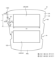
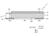
- FIG. 1 is a schematic top view of a vehicle glass unit according to the present embodiment.
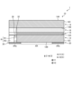
- FIG. 2 is a schematic cross-sectional view of the vehicle glass unit according to the present embodiment.
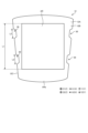
- FIG. 3 is a schematic diagram of the first glass plate.
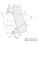
- FIG. 4 is a partial enlarged view of the cutout portion of the first glass plate.
- FIG. 5 is a schematic diagram showing another example of a vehicle glass.
- FIG. 6 is a schematic diagram showing another example of a vehicle glass.
- FIG. 7 is a schematic diagram showing another example of a vehicle glass.
- FIG. 8 is a schematic diagram showing another example of a vehicle glass.
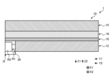
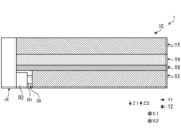
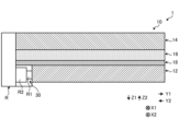
- FIG. 9 is a schematic cross-sectional view of a vehicle glass unit according to another embodiment.
- FIG. 10 is a schematic cross-sectional view of a vehicle glass unit according to another embodiment.
- FIG. 11 is a schematic cross-sectional view of a vehicle glass unit according to another embodiment.
- FIG. 1 is a schematic top view of the vehicle glass unit according to this embodiment
- FIG. 2 is a schematic cross-sectional view of the vehicle glass unit according to this embodiment.
- the vehicle glass unit 1 according to this embodiment has a vehicle glass 10 and an irradiation device R that irradiates light toward the vehicle glass 10.
- the vehicle glass unit 1 (vehicle glass 10) according to this embodiment is mounted on a vehicle and can be used, for example, as a vehicle window.
- the vehicle glass unit 1 (vehicle glass 10) may be mounted at any position of the vehicle and may be used, for example, as a roof glass, a windshield, a rear window, and a side window.
- the vehicle glass unit 1 (vehicle glass 10) is used as a roof glass provided on the roof of the vehicle.
- the vehicle glass 10 has a first glass plate 12, a second glass plate 14, an intermediate layer 16, a scattering layer 18, and a light-shielding layer 20.
- the direction perpendicular to the main surface of the vehicle glass 10 is the Z direction
- the direction toward one side of the Z direction is the Z1 direction
- the direction toward the other side of the Z direction is the Z2 direction.
- the vehicle glass 10 is laminated in the order of the second glass plate 14, the intermediate layer 16, the scattering layer 18, the first glass plate 12, and the light-shielding layer 20 toward the Z1 direction.
- the Z1 direction is the vehicle interior direction (direction toward the vehicle interior) and the Z2 direction is the vehicle exterior direction (direction toward the vehicle exterior).
- the direction perpendicular to the surface at the center position of the vehicle glass 10 may be the Z direction.
- one direction perpendicular to the Z direction is referred to as the X direction (first direction)
- the direction toward one side of the X direction is referred to as the X1 direction
- the direction toward the other side of the X direction is referred to as the X2 direction.
- the direction perpendicular to the Z direction and the X direction is referred to as the Y direction (second direction), the direction toward one side of the Y direction is referred to as the Y1 direction, and the direction toward the other side of the Y direction (opposite to the Y1 direction) is referred to as the Y2 direction.
- the Y direction is the front-rear direction of the vehicle and the X direction is the left-right direction of the vehicle.
- the relationship between the X direction and the Y direction and the direction of the vehicle is not limited thereto and may be any.
- the first glass plate 12 is a glass plate located inside the vehicle when the vehicle glass 10 is installed in the vehicle.
- the first glass plate 12 has a main surface 12A (first main surface) facing the Z2 direction, a main surface 12B (a second main surface opposite to the main surface 12A) facing the Z1 direction, and an end surface 12C connecting the main surface 12A and the main surface 12B.
- the main surfaces 12A and 12B may be called the third surface and the fourth surface of the vehicle glass 10, respectively.
- the end surface 12C is an end surface on the radial outer side of the first glass plate 12 when viewed from the Z direction, and can also be called a side surface of the first glass plate 12.
- the thickness of the first glass plate 12 is preferably 0.3 mm to 4.0 mm, more preferably 0.3 mm to 2.3 mm, more preferably 0.5 mm to 2.1 mm, and even more preferably 0.7 mm to 1.9 mm. Having a thickness within this range improves handling and prevents the mass from becoming too large, thereby suppressing a decrease in fuel efficiency of the vehicle. In addition, light is easily introduced into the glass plate, and the amount of light absorbed by the glass plate is not excessively large.
- the thickness of the first glass plate 12 refers to the length in the Z direction from the main surface 12A to the main surface 12B. For example, when the first glass plate 12 is curved, it may be the length in the Z direction from the center position of the main surface 12A to the center position of the main surface 12B.
- the first glass plate 12 may be curved. It is preferable that the first glass plate 12 is curved so as to be convex toward the Z2 direction. As shown in FIG. 3, in the example of this embodiment, the first glass plate 12 is curved so as to be convex toward the Z2 direction with the Y direction as the bending axis. However, the direction of the bending axis may be arbitrary. The bending axis here can be said to be the central axis of the circle of curvature of the first glass plate 12. The radius of curvature of the first glass sheet 12 when curved may be 100 mm or more and 10,000 mm or less. When the radius of curvature is within this range, the glass sheet 12 can be appropriately mounted on a vehicle.
- the radius of curvature of the first glass sheet 12 here refers to the radius of curvature of the bend with one direction (Y direction in the example of FIG. 3) as the bending axis.
- the first glass sheet 12 is not limited to being curved with only one direction as the bending axis, and may be a complex curved shape with multiple different directions (for example, two directions) as the bending axis.
- the radius of curvature corresponding to each bending axis is preferably within the above numerical range.
- the first glass sheet 12 is not limited to being curved, and may be flat.
- the first glass plate 12 may have any shape, but in this embodiment, the shape is such that the length in the X direction decreases as it approaches the Y2 direction.
- the first glass plate 12 is a trapezoidal flat plate whose length in the X direction decreases as it approaches the Y2 direction, curved with the Y direction as the bending axis.
- a cutout portion 30 is formed in the first glass plate 12.
- An irradiation device R is provided within the cutout portion 30. The cutout portion 30 and the irradiation device R will be described later.
- the first glass plate 12 may be made of any material, such as soda lime glass, borosilicate glass, or aluminosilicate glass.
- the first glass plate 12 may be tempered glass, and may be air-cooled tempered glass or chemically tempered glass.
- the vehicle glass unit has only one glass plate, it is preferable to use tempered glass, and it is particularly preferable to use air-cooled tempered glass.
- the multiple glass plates may include at least one of untempered glass and tempered glass.
- the second glass plate 14 is located in the Z2 direction from the first glass plate 12 and overlaps the first glass plate 12 when viewed from the Z direction. That is, the second glass plate 14 is a glass plate located on the vehicle exterior side when the vehicle glass 10 is installed in a vehicle.
- the second glass plate 14 has a main surface 14A facing the Z2 direction, a main surface 14B (main surface opposite to the main surface 14A) facing the Z1 direction, and an end surface 14C connecting the main surface 14A and the main surface 14B.
- the main surfaces 14A and 14B may be called the first surface and the second surface of the vehicle glass 10, respectively.
- the end surface 14C is an end surface on the radial outer side of the second glass plate 14 when viewed from the Z direction, and can also be called a side surface of the second glass plate 14.
- the thickness of the second glass plate 14 is preferably equal to or greater than the thickness of the first glass plate 12. However, the thickness of the second glass plate 14 may be smaller than the thickness of the first glass plate 12.
- the thickness of the second glass plate 14 is preferably 1.1 mm or more and 3.0 mm or less, more preferably 1.8 mm or more and 2.8 mm or less, even more preferably 1.8 mm or more and 2.6 mm or less, even more preferably 1.8 mm or more and 2.2 mm or less, and even more preferably 1.8 mm or more and 2.0 mm or less.
- the thickness of the second glass plate 14 refers to the length in the Z direction from the main surface 14A to the main surface 14B.
- it may be the length in the Z direction from the center position of the main surface 14A to the center position of the main surface 14B.
- Other features of the second glass plate 14 are the same as those of the first glass plate 12 described above, and therefore will not be described here. Note that the radius of curvature of the second glass plate 14 and the radius of curvature of the first glass plate 12 may be the same or different.
- the vehicle glass 10 is a laminated glass having two glass plates, a first glass plate 12 and a second glass plate 14, but the number of glass plates is not limited to this and may be three or more. As described later, the vehicle glass 10 may also be a single-pane glass having only the first glass plate 12 as a glass plate.
- the intermediate layer 16 is located between the first glass plate 12 and the second glass plate 14 in the Z direction.
- the intermediate layer 16 is an adhesive layer that bonds the first glass plate 12 and the second glass plate 14. Any material may be used for the intermediate layer 16, but a thermoplastic resin or a curable resin is preferable, and a thermoplastic resin is particularly preferable.
- thermoplastic resin polyvinyl butyral (PVB) resin, ethylene vinyl acetate copolymer (EVA) resin, polyurethane resin, ionomer resin, cycloolefin polymer, etc.
- the thermoplastic resin is selected in consideration of the balance of various performances such as glass transition point, transparency, weather resistance, adhesive strength, penetration resistance, impact energy absorption, moisture resistance, heat insulation, etc. Considering the balance of the above-mentioned various performances, the thermoplastic resin is preferably PVB resin, EVA resin, or polyurethane resin.
- the curable resin any resin that is cured by heat, light (ultraviolet rays), etc. may be used, for example, acrylic or silicone resin.
- the intermediate layer 16 is not an essential component. For example, in a configuration in which only the first glass plate 12 is provided as a glass plate, the intermediate layer 16 does not need to be provided.
- the scattering layer 18 is a layer for scattering light incident at least through the cutout portion 30 into the first glass plate 12.
- the scattering layer 18 is configured so that the light incident on the scattering layer 18 is scattered at least in the Z1 direction.
- the scattering layer 18 is a layer provided at a position overlapping the main surfaces (main surfaces 12A and 12B) of the first glass plate 12 when viewed from the Z direction (in a plan view).
- the scattering layer 18 is provided at a position overlapping the main surfaces of the first glass plate 12 and the second glass plate 14 when viewed from the Z direction. As shown in Fig.
- the scattering layer 18 is provided between the main surface 12A of the first glass plate 12 and the intermediate layer 16.
- the scattering layer 18 may be provided on the main surface 12B of the first glass plate 12 (in the Z1 direction from the main surface 12B), may be provided inside the intermediate layer 16, may be provided between the intermediate layer 16 and the main surface 14B of the second glass plate 14, or may be provided on the main surface 14B of the second glass plate 14 (in the Z1 direction from the main surface 14B).
- the material and method of forming the scattering layer 18 are not particularly limited.
- the scattering layer 18 may be formed by holding fine particles on the surface or inside of a resin sheet such as polyethylene terephthalate (PET), polyethylene (PE), polycarbonate (PC), polyurethane (PU), or silicone.
- the scattering layer 18 may also be formed by holding fine particles on the surface or inside of a thermoplastic resin or a curable resin that constitutes the intermediate layer 16.
- Fine particles are, for example, particles with a volume average particle size exceeding 0.1 ⁇ m, preferably not exceeding 10 ⁇ m.
- the volume average particle size is determined by a particle size distribution measuring device using a laser diffraction scattering method (for example, "UPA-EX150” manufactured by Nikkiso Co., Ltd.).
- the scattering layer 18 may also be formed by subjecting the surface of the glass plate to surface processing such as sandblasting or etching.
- the scattering layer 18 may also be formed by applying a white pigment or the like to the surface of the glass plate using screen printing, inkjet printing, or the like, and drying the applied material.
- the scattering layer 18 may also be formed by applying a paste containing a white pigment or the like and a fusible glass frit to the glass plate and baking the paste.
- the light-shielding layer 20 is a layer that blocks visible light.
- the visible light transmittance of the light-shielding layer 20 is usually 5% or less, preferably 3% or less, and may be substantially 0%.
- the light-shielding layer 20 is a layer provided at a position overlapping a partial region of the main surface (main surface 12A and main surface 12B) of the first glass plate 12 when viewed from the Z direction.
- the light-shielding layer 20 is provided at a position overlapping a partial region of the main surface of the first glass plate 12 and a partial region of the main surface of the second glass plate 14 when viewed from the Z direction.
- the light-shielding layer 20 is provided on the main surface 12B of the first glass plate 12 (in the Z1 direction from the main surface 12B).
- the light-shielding layer 20 when viewed from the Z direction (in a plan view), the light-shielding layer 20 is provided with a predetermined width on the peripheral portion of the first glass plate 12.
- the position at which the light-shielding layer 20 is provided is not limited thereto and may be any position.
- the light-shielding layer 20 may be provided on the main surface 14B of the second glass plate 14 (in the Z1 direction from the main surface 14B), or may be provided on both the main surface 12B of the first glass plate 12 and the main surface 14B of the second glass plate 14.
- the material of the light-shielding layer 20 may be any material.
- a ceramic light-shielding layer or a light-shielding film can be used as the light-shielding layer 20.
- a ceramic layer made of a conventionally known material such as a black ceramic layer can be used as the ceramic light-shielding layer.
- a light-shielding polyethylene terephthalate (PET) film, a light-shielding polyethylene naphthalate (PEN) film, a light-shielding polymethyl methacrylate (PMMA) film, or the like can be used as the light-shielding film.
- PET light-shielding polyethylene terephthalate
- PEN light-shielding polyethylene naphthalate
- PMMA light-shielding polymethyl methacrylate
- the light-shielding layer 20 is not an essential component. In other words, the vehicle glass unit 1 does not need to have the light-shielding
- the vehicle glass 10 is formed with a transmission area AR.
- the transmission area AR refers to an area that transmits light scattered by the scattering layer 18 in the entire area of the main surface of the vehicle glass 10.
- the area in which the scattering layer 18 is provided when viewed from the Z direction is the transmission area AR. That is, the light incident from the irradiation device R into the first glass plate 12 is transmitted or blocked without being scattered by the scattering layer 18 in the area in which the scattering layer 18 is not provided.
- the light incident from the irradiation device R into the first glass plate 12 is scattered by the scattering layer 18 and is guided in the Z1 direction through the transmission area AR in which the scattering layer 18 is provided.
- the transmission region AR can be said to be a region where the scattering layer 18 is provided and where the light-shielding layer 20 is not provided, when viewed from the Z direction. That is, the light incident on the first glass plate 12 from the irradiation device R is blocked in the region where the light-shielding layer 20 is provided and is not transmitted in the Z1 direction. On the other hand, the light scattered by the scattering layer 18 is not blocked by the light-shielding layer 20 in the region where the light-shielding layer 20 is not provided and transmits in the Z1 direction.
- the transmissive region AR has a rectangular shape when viewed from the Z direction.
- two transmissive regions AR1 and AR2 aligned in the Y direction are formed as the transmissive region AR.
- the shape of the transmissive region AR is not limited thereto and may be any shape, and the number and alignment direction of the transmissive regions AR may also be any shape.
- the area other than the transmissive area AR in the entire area of the main surface of the vehicle glass 10 will be referred to as a non-transmissive area ARa as appropriate.
- the non-transmissive area ARa can be said to be an area that satisfies at least one of the following when viewed from the Z direction: the scattering layer 18 is not provided, and the light-shielding layer 20 is provided.
- the light-shielding layer 20 in the non-transmissive area ARa includes at least a portion that is disposed further in the Z1 direction than the scattering layer 18.
- the length of the transmission area AR in the Y direction is defined as length L1.
- the length L1 is preferably 50 mm or more and 1500 mm or less, preferably 150 mm or more and 1000 mm or less, and more preferably 300 mm or more and 800 mm or less.
- the length of the transmission area AR in the X direction is defined as length D1.
- the length D1 is preferably 500 mm or more and 1200 mm or less, preferably 600 mm or more and 1000 mm or less, and more preferably 700 mm or more and 900 mm or less.
- the length L1 may refer to the length of a line connecting an end of the transmissive region AR in the Y1 direction and an end of the transmissive region AR in the Y2 direction along the main surface of the first glass plate 12.
- the length D1 may refer to the length of a line connecting an end of the transmissive region AR in the X1 direction and an end of the transmissive region AR in the X2 direction along the main surface of the first glass plate 12.
- the vehicle glass 10 has the above-mentioned configuration. However, the vehicle glass 10 may have layers other than those mentioned above.
- the vehicle glass 10 may be provided with a low-emissivity (Low-E) layer or an infrared reflective/absorbent layer at a position overlapping with the main surface of the first glass plate 12 when viewed from the Z direction.
- the low-emissivity layer is a layer that reduces radiation, and may be, for example, a film containing a metal oxide such as tin oxide or a metal such as silver.
- the emissivity of the low-emissivity layer is, for example, less than 0.3.
- the low-emissivity layer may be provided, for example, on the main surface 12B of the first glass plate 12 (in the Z1 direction from the main surface 12B).
- the infrared reflective/absorbent layer may be provided, for example, on the main surface 14B of the second glass plate 14 (in the Z1 direction from the main surface 14B).
- the cutout portion 30 formed in the first glass plate 12 will be described.
- the cutout portion 30 is a cutout formed in the end surface 12C of the first glass plate 12.
- the cutout portion 30 penetrates from the main surface 12A to the main surface 12B of the first glass plate 12.
- the cutout portion 30 is recessed toward the inside (radial inner side) of the first glass plate 12, and in this embodiment, is recessed toward the X direction.
- the cutout portion 30 is formed in at least one of the end surface 12C in the X2 direction of the first glass plate 12 and the end surface 12C in the X1 direction of the first glass plate 12.
- the cutout portion 30 provided in the end surface 12C in the X2 direction is recessed toward the X1 direction, and the cutout portion 30 provided in the end surface 12C in the X1 direction is recessed toward the X2 direction.
- the notch 30 is preferably formed on both the end face 12C of the first glass plate 12 in the X2 direction and the end face 12C of the first glass plate 12 in the X1 direction.
- the cutout portion 30 is preferably formed at a position overlapping the transmission region AR when viewed from the X direction.
- the cutout portion 30 is preferably located in the X direction of the transmission region AR when viewed from the Z direction. That is, for example, the cutout portion 30 provided on the end face 12C in the X2 direction is located in the X2 direction of the transmission region AR, and the cutout portion 30 provided on the end face 12C in the X1 direction is located in the X1 direction of the transmission region AR.
- only one cutout portion 30 is formed on one side of one transmission region AR in the X direction.
- one cutout portion 30 located in the X1 direction and one cutout portion 30 located in the X2 direction are formed for one transmission region AR.
- one cutout portion 30 is formed in each of the X1 direction and the X2 direction of the transmission regions AR1 and AR2.
- the number of cutout portions 30 for the transmission region AR may be arbitrary, and a plurality of cutout portions 30 aligned in the Y direction may be formed on one or both sides of the X direction for one transmission region AR.
- FIG. 4 is a partial enlarged view of the cutout portion of the first glass plate.
- the shape and size of the cutout portion 30 may be arbitrary, but as shown in FIG. 4, in this embodiment, the cutout portion 30 has a bottom surface portion 32, a first side surface portion 34, and a second side surface portion 36.
- the cutout portion 30 formed on the end surface 12C in the X2 direction will be used as an example.
- the cutout portion 30 formed on the end surface 12C in the X1 direction is similar to the cutout portion 30 formed on the end surface 12C in the X2 direction except that the X1 and X2 directions are reversed, so a description of the cutout portion 30 will be omitted.
- the bottom surface portion 32 of the cutout portion 30 is a surface including the portion that is most recessed by the cutout portion 30, and can be said to be the surface of the region in which the cutout portion 30 is formed among the entire region of the edge surface 12C of the first glass plate 12.
- the first side surface portion 34 is a side surface located in the Y1 direction of the bottom surface portion 32, and connects the bottom surface portion 32 and the edge surface 12C.
- the second side surface portion 36 is a side surface located in the Y2 direction of the bottom surface portion 32, and connects the bottom surface portion 32 and the edge surface 12C.
- the cutout portion 30 is a recess formed by the bottom surface portion 32, the first side surface portion 34, and the second side surface portion 36.
- connection portion 34A is preferably a curved surface (curved shape) recessed inward when viewed from the Z direction.
- connection portion 34A is preferably a curved surface recessed toward the X1 direction.
- connection portion 34B is preferably a curved surface protruding outward when viewed from the Z direction.
- connection portion 34B is preferably a curved surface protruding toward the X2 direction.
- connection portion 36A is a curved surface that is recessed inward when viewed from the Z direction.
- connection portion 36B is a curved surface that protrudes outward when viewed from the Z direction.
- connection portion 36B is a curved surface that protrudes toward the X2 direction.
- the radius of curvature of the bottom surface portion 32 with the Z direction as the bending axis is preferably 100 mm or more, more preferably 200 mm or more and 10,000 mm or less, and even more preferably 300 mm or more and 8,000 mm or less.
- the radius of curvature of the bottom surface portion 32 with the Z direction as the bending axis is preferably equal to or greater than the radius of curvature of the connection points 34A, 34B, 36A, and 36B with the Z direction as the bending axis.
- the depth (length in the X direction) of the cutout portion 30 relative to the width (length in the Y direction) of the cutout portion 30 can be kept small, which is preferable from the standpoint of strength and manufacturing process.
- the radius of curvature of the connection points 34A, 34B, 36A, and 36B, with the Z direction as the bending axis is preferably 30 mm or more and 1200 mm or less, more preferably 50 mm or more and 1000 mm or less, and even more preferably 80 mm or more and 800 mm or less.
- the radius of curvature of the connection points 34A, 34B, 36A, and 36B can be made small enough to appropriately capture light from the irradiation device R, while suppressing cracks originating from the connection points 34A, 34B, 36A, and 36B due to the radius of curvature being too small.
- the length L2 which is the length (width) in the Y direction of the cutout portion 30, is preferably 50 mm or more and 800 mm or less, more preferably 100 mm or more and 500 mm or less, and even more preferably 150 mm or more and 300 mm or less.
- the length L2 800 mm or less it is possible to appropriately emit light without increasing the number of irradiation units R1 included in the irradiation device R, which will be described later, and also to suppress a decrease in the strength of the first glass plate 12.
- the length L2 may be the distance from the position P1 at the intersection of the line A1 and the line A2 to the position P2 at the intersection of the line A1 and the line A3 as viewed from the Z direction.
- the line A1 is an approximation line of the section of the end face 12C other than the section where the notch portion 30 is formed as viewed from the Z direction.
- the line A1 is obtained by approximating the profile of the end face 12C in the section where the notch portion 30 is not formed as viewed from the Z direction with a straight line.
- the line A2 is an approximation line of the first side portion 34 as viewed from the Z direction.
- the line A2 is obtained by approximating the profile of the first side portion 34 in the section between a position 5 mm away from the center position of the first side portion 34 in the Y direction in the Y1 direction and a position 5 mm away from the center position as viewed from the Z direction in the Y direction with a straight line.
- the line A3 is an approximation line of the second side portion 36 as viewed from the Z direction.
- Line A3 is obtained by approximating the profile of the second side portion 36 as viewed from the Z direction in the section between a position 5 mm away in the Y1 direction from the center position of the second side portion 36 in the Y direction and a position 5 mm away in the Y2 direction from the center position, as viewed from the Z direction.
- the length D2 which is the length (depth) of the cutout portion 30 in the X direction, is preferably 3 mm to 200 mm, more preferably 5 mm to 150 mm, and even more preferably 10 mm to 100 mm.
- the irradiation device R can be appropriately positioned within the cutout portion 30 to appropriately capture light, suppress a decrease in the strength of the first glass plate 12, and also enable the manufacturing process to be performed appropriately.
- the length D2 may be the distance between the most recessed position of the bottom surface portion 32 and the line A1 when viewed from the Z direction.
- the ratio (L2/D2) of the length L2 of the cutout portion 30 to the length D2 is preferably 0.025 or more and 260 or less, more preferably 0.65 or more and 100 or less, even more preferably 1.0 or more and 50 or less, and even more preferably 1.5 or more and 30 or less. Having a ratio within this range allows light to be appropriately taken in, suppresses a decrease in the strength of the first glass plate 12, and also allows the manufacturing process to be carried out appropriately.
- the opening angle ⁇ of the cutout portion 30 when viewed from the Z direction is preferably 0° to 120°, more preferably 5° to 90°, and even more preferably 10° to 45°.
- the opening angle ⁇ may be the angle between the line A2 and the line A3 when viewed from the Z direction.
- the maximum valley depth Rv of the bottom surface portion 32 as defined in the 2013 JIS B0601 "Geometric Product Specifications (GPS) - Surface Texture: Profile Curve Method - Terms, Definitions and Surface Texture Parameters” is preferably smaller (smoother) than the maximum valley depth Rv at the portion of the end face 12C where the notch portion 30 is not formed.
- the maximum valley depth Rv of the bottom surface portion 32 as defined in the 2013 JIS B0601 is preferably 0.6 ⁇ m or less, and more preferably 0.2 ⁇ m or less.
- the total length L2A is the sum of the lengths L2 of the cutout portions 30 located on one side in the X direction for one transmission region AR. That is, in the example of Fig. 3, the number of cutout portions 30 located on one side in the X direction (the X2 direction in this example) for one transmission region AR is one, so the total length L2A can be said to be the length L2 of that cutout portion 30. On the other hand, for example, if there are a plurality of cutout portions 30 located on one side in the X direction (the X2 direction in this example) for one transmission region AR, the total length L2A refers to the sum of the lengths L2 of those cutout portions 30.
- the ratio (L2A/L1) of the total length L2A of the cutout portion 30 located on one side of the X direction with respect to the length L1 of the transmission region AR is preferably 1/8 or more, more preferably 1/2 or more, and even more preferably 2/3 or more.
- the ratio (L2A/L1) is preferably 1.0 or less, more preferably 5/6 or less, and even more preferably 4/5 or less. That is, the ratio (L2A/L1) is preferably 1/8 or more and 1.0 or less, more preferably 1/2 or more and 5/6 or less, and even more preferably 2/3 or more and 4/5 or less.
- the ratio (L2A/L1) By setting the ratio (L2A/L1) to 1/8 or more, it is possible to appropriately take in the light from the irradiation device R into the first glass plate 12, and to make the intensity of the light scattered by the scattering layer 18 and led out in the Z1 direction closer to uniform. Furthermore, by setting the ratio (L2A/L1) to 1.0 or less, it becomes possible to appropriately emit light without increasing the number of irradiation sections R1 (described later) included in the irradiation device R, and also makes it possible to suppress a decrease in the strength of the first glass plate 12.
- the distance ⁇ D between the transmission area AR and the cutout portion 30 located on one side of the transmission area AR in the X direction is preferably 200 mm or less, more preferably 5 mm or more and 100 mm or less, and even more preferably 10 mm or more and 30 mm or less.
- the intensity of the light emitted from the transmission area AR in the Z1 direction can be made closer to uniform.
- the first glass plate 12 has a corner 12ED.
- the corner 12ED is a boundary between one end face 12C in the X direction and one end face 12C in the Y direction.
- the distance ⁇ ED between the cutout 30 and the corner 12ED closest to the cutout 30 is preferably 30 mm or more, more preferably 50 mm or more and 500 mm or less, and even more preferably 80 mm or more and 300 mm or less.
- the cutout portion 30 overlaps with the light-shielding layer 20 when viewed from the Z direction.
- the cutout portion 30 overlaps with the light-shielding layer 20 when viewed from the Z direction.
- the irradiation device R is a device that irradiates light (visible light) into the first glass plate 12. As shown in FIG. 1, the irradiation device R has an irradiation section R1 and a substrate R2.
- the irradiation section R1 is a part of the irradiation device R that emits light, and in this embodiment, it is a light source such as an LED that emits light.
- the substrate R2 is a substrate connected to the irradiation section R1.
- a plurality of irradiation sections R1 are provided so as to be aligned in the Y direction, and it is preferable that the distance between adjacent irradiation sections R1 in the Y direction is uniform.
- the number of irradiation sections R1 is preferably 3 to 50, more preferably 5 to 30, and even more preferably 10 to 20. By the number of irradiation sections R1 being within this range, the intensity of the light transmitted from the transmission area AR1 in the Z1 direction can be sufficiently maintained.
- the number of irradiation sections R1 and the direction in which they are aligned are not limited to this and may be arbitrary.
- the irradiation unit R1 is not limited to being a light source such as an LED.
- the irradiation device R may be configured to include a light source, a light guide through which light from the light source passes, and an outlet formed in the light guide and capable of transmitting light.
- the outlet formed in the light guide corresponds to the irradiation unit R1. That is, in this configuration, the light irradiated from the light source into the light guide is emitted from the irradiation unit R1, which is the outlet.
- the irradiation device R is at least partially mounted within the cutout portion 30. Specifically, it is preferable that the irradiation device R is mounted within the cutout portion 30 so that at least the portion that emits light of the irradiation section R1 faces the bottom surface portion 32 of the cutout portion 30. When multiple cutout portions 30 are formed, it is preferable that the irradiation device R is at least partially mounted within each of the cutout portions 30.
- the vehicle glass unit 1 is configured as described above.
- the light emitted from the irradiation unit R1 of the irradiation device R enters the first glass plate 12 from the bottom surface 32 of the cutout portion 30 facing the irradiation device R.
- the light that enters the first glass plate 12 travels in the X direction while being reflected by the main surfaces 12A and 12B of the first glass plate 12.
- a part of the light that enters the first glass plate 12 passes through the main surface 12A and is scattered by the scattering layer 18, travels in the Z1 direction, and is emitted in the Z1 direction from the transmission area AR of the main surface 12B.
- the light scattered by the scattering layer 18 passes through almost the entire transmission area AR in the Z1 direction (inside the vehicle) and is visible inside the vehicle.
- the vehicle glass 10 has a first glass plate 12 and a scattering layer 18, and a cutout portion 30 is formed on the end surface 12C of the first glass plate 12. Therefore, by attaching the irradiation device R to the cutout portion 30, light from the irradiation device R can be taken into the first glass plate 12 from the cutout portion 30, so that the light can be appropriately taken into the first glass plate 12.
- the irradiation device R can be arranged in the cutout portion 30, it is possible to prevent the irradiation device R from protruding from the vehicle glass 10, and it is possible to easily install it in the vehicle.
- the cutout portion 30 for mounting the irradiation device R is formed in advance, so the size of the cutout portion 30 can be adjusted to prevent a decrease in strength.
- FIG. 5 is a schematic diagram showing another example of vehicle glass.
- the distance ⁇ D between the transparent region AR and the cutout 30 in the X direction of the transparent region AR may be uniform. More specifically, when multiple cutouts 30 arranged in the Y direction are formed on one side of the X direction, the distance ⁇ D between each cutout 30 and the transparent region AR may be uniform.
- the transparent regions AR1 and AR2 arranged in the Y direction are formed, the distance ⁇ D between the transparent region AR1 and its cutout 30 in the X1 direction and the distance ⁇ D between the transparent region AR2 and its cutout 30 in the X1 direction are uniform.
- the distance ⁇ D between the transparent region AR1 and its cutout 30 in the X2 direction and the distance ⁇ D between the transparent region AR2 and its cutout 30 in the X2 direction are uniform.
- the length of the first glass plate 12 in the X direction increases in the Y1 direction, so the area of the cutout portion 30 located in the X direction of the transmissive region AR1 is larger than the area of the cutout portion 30 located in the X direction of the transmissive region AR2 that is closer to the Y2 direction than the transmissive region AR1.
- the distance ⁇ D of each cutout portion 30 may be uniform.
- the distance ⁇ D being uniform does not necessarily mean that the distances ⁇ D are exactly the same value, and may include a general error (for example, an error of about 3 mm or less).
- the distance from the irradiation device R to the transmission area AR can be made uniform, so that the intensity of the light transmitted from the transmission area AR can be made closer to uniform.
- the method of making the intensity of the light transmitted from the over-region AR closer to uniform is not limited to making the distance ⁇ D uniform.
- the intensity of the light from the irradiation device R mounted on the cutout 30 may be set higher as the distance ⁇ D from the cutout 30 to the transmission region AR becomes longer. This allows the intensity of the light at the position where the distance ⁇ D is long and the light is easily attenuated to be increased in advance, making it possible to make the intensity of the light transmitted from the transmission region AR closer to uniform.
- FIG. 6 is a schematic diagram showing another example of a vehicle glass.
- the region between the transmission region AR and the cutout portion 30 located in the X direction relative to the transmission region AR was a non-transmission region ARa in which the light-shielding layer 20 was provided.
- the region between the transmission region AR and the cutout portion 30 located in the X direction relative to the transmission region AR may be a non-light-shielding region ARB in which the light-shielding layer 20 is not provided. That is, when viewed from the Z direction, the light-shielding layer 20 may not be provided in the region between the transmission region AR and the cutout portion 30.
- the scattering layer 18 may or may not be formed in the non-light-shielding region ARB between the transmission region AR and the cutout portion 30.
- FIG. 7 is a schematic diagram showing another example of vehicle glass.
- the vehicle glass 10 may have one transmissive area AR.
- two cutout portions 30 aligned in the Y direction are formed in each of the X1 and X2 directions of the transmissive area AR.
- the number of cutout portions 30 formed in the X1 and X2 directions of the transmissive area AR may be any number.
- FIG. 8 is a schematic diagram showing another example of vehicle glass.
- the vehicle glass 10 is a laminated glass having a first glass plate 12 and a second glass plate 14.
- the vehicle glass 10 may be a single-pane glass having a first glass plate 12, which is a single glass plate.
- the vehicle glass 10 may have the first glass plate 12, a scattering layer 18, and a light-shielding layer 20.
- the scattering layer 18 is provided on the main surface 12A of the first glass plate 12, but is not limited thereto, and may be provided on the main surface 12B of the first glass plate 12, for example.
- FIG. 9 to 11 are schematic cross-sectional views of vehicle glass units according to other examples.
- the entire irradiation device R is disposed within the cutout portion 30 of the first glass plate 12.
- the present invention is not limited to this. Only a part of the irradiation device R may be located within the cutout portion 30, and the other part may protrude from the cutout portion 30.
- the irradiation device R may be provided from within the cutout portion 30 to a position protruding from within the cutout portion 30 in the Z direction (Z1 direction in this example).
- the irradiation device R may be provided from within the cutout portion 30 to a position protruding from within the cutout portion 30 in the Y direction (Y2 direction in this example).
- the portion of the irradiation device R protruding from within the cutout portion 30 in the Y direction may have any shape.
- the protruding portion may extend in the Z2 direction to a position facing the end face of the scattering layer 18 in the Y direction, a position facing the end face of the intermediate layer 16 in the Y direction, and a position facing the end face of the second glass plate 14 in the Y direction, as shown in FIG.
- the irradiation device R may protrude from the inside of the cutout portion 30 in both the Y direction and the Z direction. In this manner, when the irradiation device R protrudes from within the cutout portion 30, it is preferable that the irradiation section R1 of the irradiation device R is located within the cutout portion 30, and a portion of the irradiation device R other than the irradiation section R1 protrudes from the cutout portion 30.
- the portion of the irradiation device R other than the irradiation section R1 may be, for example, a housing that houses the irradiation section R1.
- the vehicle glass 10 has a first glass plate 12 including a main surface including a main surface 12A (first main surface) and a main surface 12B (second main surface) opposite to the main surface 12A, and an end surface 12C connecting the main surface 12A and the main surface 12B, and a scattering layer 18 overlapping the main surface of the first glass plate 12 in a plan view.
- the end surface 12C of the first glass plate 12 has a cutout portion 30 formed therein that is recessed inward in a plan view and penetrates from the main surface 12A to the main surface 12B, and the scattering layer 18 scatters light that enters the first glass plate 12 from the cutout portion 30.
- the vehicle glass 10 of the present disclosure can have an irradiation device R attached to the cutout portion 30 so that light from the irradiation device R can be taken in through the cutout portion 30 into the first glass plate 12, thereby enabling the light to be appropriately taken in into the first glass plate 12.
- the vehicle glass 10 according to the second aspect of the present disclosure is the vehicle glass 10 according to the first aspect, and when the direction perpendicular to the Z direction (thickness direction of the first glass plate 12) is the X direction (first direction) and the direction perpendicular to the Z direction and the X direction is the Y direction (second direction), the cutout portion 30 is recessed toward the X direction and overlaps with the transmission area AR that transmits the light scattered by the scattering layer 18 when viewed from the X direction.
- the ratio (L2A/L1) of the total length L2A to the length L1 is 1/8 or more.
- the ratio of the total length L2A to the length L1 is within this range, it is possible to appropriately take in the light from the irradiation device R into the first glass plate 12 and make the light scattered by the scattering layer 18 and led out in the Z1 direction closer to uniform.
- the vehicle glass 10 according to the third aspect of the present disclosure is the vehicle glass 10 according to the second aspect, and preferably has a ratio (L2A/L1) of the total length L2A to the length L1 of 1.0 or less.
- the ratio is in this range, it is possible to appropriately emit light without increasing the number of irradiation sections R1 included in the irradiation device R, and also to suppress a decrease in the strength of the first glass plate 12.
- the vehicle glass 10 according to the fourth aspect of the present disclosure is the vehicle glass 10 according to any one of the first to third aspects, and the length D2 of the cutout portion 30 in the X direction is preferably 3 mm or more and 200 mm or less.
- the irradiation device R can be appropriately positioned within the cutout portion 30 to appropriately capture light, suppress a decrease in the strength of the first glass plate 12, and also allow the manufacturing process to be performed appropriately.
- the vehicle glass 10 according to the fifth aspect of the present disclosure is the vehicle glass 10 according to any one of the first to fourth aspects, and it is preferable that the length L2 of the cutout portion 30 in the Y direction is 50 mm or more and 800 mm or less. By setting the length L2 within this range, it can be appropriately incorporated into the first glass plate 12.
- the vehicle glass 10 according to the sixth aspect of the present disclosure is the vehicle glass 10 according to any one of the first to fifth aspects, and the cutout portion 30 is preferably recessed in the X direction.
- the cutout portion 30 preferably has a bottom surface portion 32 which is the surface of the end surface 12C on which the cutout portion 30 is formed, a first side surface portion 34 located on one side of the bottom surface portion 32 in the Y direction and connecting the bottom surface portion 32 to the end surface 12C, and a second side surface portion 36 located on the other side of the bottom surface portion 32 in the Y direction and connecting the bottom surface portion 32 to the end surface 12C.
- the vehicle glass 10 according to the seventh aspect of the present disclosure is the vehicle glass 10 according to the sixth aspect, and in plan view, the radius of curvature of the bottom surface 32 is preferably 100 mm or more.
- the radius of curvature of the bottom surface 32 is preferably 100 mm or more.
- the vehicle glass 10 according to the eighth aspect of the present disclosure is the vehicle glass 10 according to the sixth or seventh aspect, and it is preferable that the connection point 34A between the first side portion 34 and the bottom surface portion 32 and the connection point 36A between the second side portion 36 and the bottom surface portion 32 are concave curved surfaces in a plan view, and the connection point 34B between the first side portion 34 and the end surface 12C and the connection point 36B between the second side portion 36 and the end surface 12C are convex curved surfaces in a plan view.
- the vehicle glass 10 according to the ninth aspect of the present disclosure is the vehicle glass 10 according to the eighth aspect, and preferably has a radius of curvature of the connection points 34A, 34B, 36A, and 36B of 30 mm or more and 1200 mm or less.
- a radius of curvature of the connection points 34A, 34B, 36A, and 36B of 30 mm or more and 1200 mm or less.
- the vehicle glass 10 according to the tenth aspect of the present disclosure is the vehicle glass 10 according to any one of the first to ninth aspects, and the bottom surface 32 of the cutout portion 30 preferably has a maximum valley depth Rv of 0.6 ⁇ m or less as specified in JIS B0601 of 2013. By setting the surface roughness of the bottom surface 32 within this range, it is possible to appropriately capture light from the irradiation device R.
- the vehicle glass 10 according to the eleventh aspect of the present disclosure is the vehicle glass 10 according to any one of the first to tenth aspects, in which the first glass plate 12 has a corner 12ED in a plan view, and the distance ⁇ ED between the cutout 30 and the corner 12ED is preferably 30 mm or more. By setting the distance ⁇ ED within this range, the cutout 30 is sufficiently separated from the corner 12ED, and cracks originating from the cutout 30 can be appropriately suppressed.
- the vehicle glass 10 according to the twelfth aspect of the present disclosure is the vehicle glass 10 according to any one of the first to eleventh aspects, and it is preferable that the distance ⁇ D between the bottom surface portion 32 of the cutout portion 30 and the transmission area AR is 200 mm or less. By setting the distance ⁇ D within this range, the intensity of the light emitted from the transmission area AR in the Z1 direction can be made closer to uniform.
- the vehicle glass 10 according to the thirteenth aspect of the present disclosure is the vehicle glass 10 according to any one of the first to twelfth aspects, and preferably further comprises a second glass plate 14 that overlaps with the first glass plate 12 in a plan view, and an intermediate layer 16 provided between the first glass plate 12 and the second glass plate 14. By forming it into a laminated glass in this way, it can be appropriately used as vehicle glass.
- the vehicle glass 10 according to the fourteenth aspect of the present disclosure is the vehicle glass 10 according to any one of the first to thirteenth aspects, and is preferably installed on the ceiling of a vehicle.
- the vehicle glass 10 By using the vehicle glass 10 as a roof glass, it is possible to appropriately emit light toward the interior of the vehicle.
- the vehicle glass unit 1 according to the fifteenth aspect of the present disclosure includes a vehicle glass 10 according to any one of the first to fourteenth aspects, and an irradiation device R that is attached to the cutout portion 30 and irradiates light toward the bottom surface portion 32 of the cutout portion 30. According to the present disclosure, light from the irradiation device R can be taken into the first glass plate 12 from the cutout portion 30, so that the light can be appropriately taken into the first glass plate 12.
- Table 1 shows vehicle glass of each example and the evaluation results thereof.
- Example 1 In Example 1, a simulation model of a glass plate having a length of 500 mm in the X direction, a length of 800 mm in the Y direction, and a thickness of 2 mm was prepared, and one notch was formed on the end face of the glass plate in the X direction, and a part of the glass plate was made into a transmission area.
- the length (width) L1 of the transmission area in the Y direction, the length (width) L2 of the notch in the Y direction, the length (depth) D2 of the notch in the X direction, and the distance ⁇ D from the notch to the transmission area were as shown in Table 1.
- the ratio (L2/L1) of the length L2 to the length L1 was as shown in Table 1.
- irradiation units were arranged in the Y direction within the notch.
- the number of arranged irradiation units is shown in Table 1.
- An optical simulation (manufactured by AGC) was performed using the above-described simulation model. In the optical simulation, light was irradiated from each irradiation unit, and the intensity of light transmitted in the Z2 direction from the transmission region was analyzed.
- Example 2 In Example 2, except that no cutout was formed and an irradiation unit was disposed on the end face of the glass plate, an optical simulation was performed in the same manner as in Example 1. Note that, since no cutout was formed in Example 2, the distance ⁇ D from the cutout to the transmission region is the distance from the end face of the glass plate in the X direction to the transmission region.
- Example 1 which is an embodiment in which a cutout portion is provided, was evaluated as A, indicating that light can be appropriately taken in.
- Example 2 which is a comparative example in which a cutout portion is not provided, was evaluated as B, indicating that light cannot be appropriately taken in.
- the embodiments of the present invention have been described above, the embodiments are not limited to the contents of these embodiments.
- the aforementioned components include those that a person skilled in the art would easily imagine, those that are substantially the same, and those that are within the scope of what is known as equivalence.
- the aforementioned components can be combined as appropriate.
- various omissions, substitutions, or modifications of the components can be made without departing from the spirit of the aforementioned embodiments.
- Vehicle glass unit 10 Vehicle glass 12 First glass plate 12A, 12B Main surface 12C End surface 14 Second glass plate 16 Intermediate layer 18 Scattering layer 20 Light-shielding layer 30 Notch portion AR Transmission region R Irradiation device
Landscapes
- Engineering & Computer Science (AREA)
- Mechanical Engineering (AREA)
- Surface Treatment Of Glass (AREA)
Abstract
ガラス板内に光を適切に取り込む。車両用ガラス(10)は、第1主面、及び第1主面と反対側の第2主面を含む主面と、第1主面と第2主面とを接続する端面(12C)とを含む第1ガラス板(12)と、平面視において第1ガラス板(12)の主面と重なる散乱層(18)と、を有する。第1ガラス板(12)の端面(12C)には、平面視において内側に凹み、第1主面から第2主面まで貫通する切り欠き部(30)が形成されており、散乱層(18)は、切り欠き部(30)から第1ガラス板(12)内に入射した光を散乱させる。
Description
本発明は、車両用ガラス、及び車両用ガラスユニットに関する。
車両用ガラスとして、発光ダイオード(LED:Light Emitting Diode)等の光源を用いて合わせガラスの端部から合わせガラスの内部に照射光を導入し、合わせガラスに設けられた散乱層を用いて光を取り出す構成が知られている。例えば特許文献1には、車内側のガラス板の端面や背面にLEDを配置し、合わせガラス内を導光させて発光する車両用グレージングに関する技術が開示されている。
このような車両用ガラスにおいては、ガラス板内に光を適切に取り込むことが求められている。
本発明は、ガラス板内に光を適切に取り込むことが可能な車両用ガラス及び車両用ガラスユニットを提供することを目的とする。
本開示に係る車両用ガラスは、第1主面、及び前記第1主面と反対側の第2主面を含む主面と、前記第1主面と前記第2主面とを接続する端面とを含む第1ガラス板と、平面視において前記第1ガラス板の前記主面と重なる散乱層と、を有し、前記第1ガラス板の前記端面には、平面視において内側に凹み、前記第1主面から前記第2主面まで貫通する切り欠き部が形成されており、前記散乱層は、前記切り欠き部から前記第1ガラス板内に入射した光を散乱させる。
本開示に係る車両用ガラスユニットは、前記車両用ガラスと、前記切り欠き部に取り付けられて、前記切り欠き部の底面部に向けて光を照射する照射装置とを有する。
本発明によれば、ガラス板内に光を適切に取り込むことができる。
以下に添付図面を参照して、本発明の好適な実施形態を詳細に説明する。なお、この実施形態により本発明が限定されるものではなく、また、実施形態が複数ある場合には、各実施形態を組み合わせて構成するものも含むものである。また、数値については四捨五入の範囲が含まれる。
(車両用ガラスユニット)
図1は、本実施形態に係る車両用ガラスユニットの模式的な上面図であり、図2は、本実施形態に係る車両用ガラスユニットの模式的な断面図である。図1に示すように、本実施形態に係る車両用ガラスユニット1は、車両用ガラス10と、車両用ガラス10に向けて光を照射する照射装置Rとを有する。本実施形態に係る車両用ガラスユニット1(車両用ガラス10)は、車両に搭載され、例えば車両窓として使用できる。車両用ガラスユニット1(車両用ガラス10)は、車両の任意の位置に搭載されてよく、例えばルーフガラス、ウインドシールド、リアウインドウ、及びサイドウインドウに用いられてよい。本実施形態の例では、車両用ガラスユニット1(車両用ガラス10)は、車両の天井に設けられるルーフガラスとして用いられる。
図1は、本実施形態に係る車両用ガラスユニットの模式的な上面図であり、図2は、本実施形態に係る車両用ガラスユニットの模式的な断面図である。図1に示すように、本実施形態に係る車両用ガラスユニット1は、車両用ガラス10と、車両用ガラス10に向けて光を照射する照射装置Rとを有する。本実施形態に係る車両用ガラスユニット1(車両用ガラス10)は、車両に搭載され、例えば車両窓として使用できる。車両用ガラスユニット1(車両用ガラス10)は、車両の任意の位置に搭載されてよく、例えばルーフガラス、ウインドシールド、リアウインドウ、及びサイドウインドウに用いられてよい。本実施形態の例では、車両用ガラスユニット1(車両用ガラス10)は、車両の天井に設けられるルーフガラスとして用いられる。
(車両用ガラス)
図2に示すように、車両用ガラス10は、第1ガラス板12と、第2ガラス板14と、中間層16と、散乱層18と、遮光層20とを有する。ここで、車両用ガラス10の主面に垂直な方向(車両用ガラス10の厚み方向)をZ方向とし、Z方向のうちで一方に向かう方向をZ1方向、Z方向のうちで他方に向かう方向(Z1方向と反対方向)をZ2方向とする。本実施形態の例では、車両用ガラス10は、Z1方向に向けて、第2ガラス板14、中間層16、散乱層18、第1ガラス板12、遮光層20の順で積層されている。なお、車両用ガラス10が車両に搭載された場合には、Z1方向が車内方向(車内に向かう方向)でありZ2方向が車外方向(車外に向かう方向)となる。また例えば、車両用ガラス10が湾曲していた場合には、車両用ガラス10の中心位置における表面に垂直な方向をZ方向としてよい。
以降において、Z方向に垂直な一方向をX方向(第1方向)とし、X方向のうちで一方に向かう方向をX1方向、X方向のうちで他方に向かう方向(X1方向と反対方向)をX2方向とする。また、Z方向及びX方向に垂直な方向をY方向(第2方向)とし、Y方向のうちで一方に向かう方向をY1方向、Y方向のうちで他方に向かう方向(Y1方向と反対方向)をY2方向とする。本実施形態では、車両用ガラス10が車両に搭載された場合には、Y方向が車両の前後方向となりX方向が車両の左右方向となる。ただし、X方向及びY方向と車両の方向との関係はそれに限られず任意であってよい。
図2に示すように、車両用ガラス10は、第1ガラス板12と、第2ガラス板14と、中間層16と、散乱層18と、遮光層20とを有する。ここで、車両用ガラス10の主面に垂直な方向(車両用ガラス10の厚み方向)をZ方向とし、Z方向のうちで一方に向かう方向をZ1方向、Z方向のうちで他方に向かう方向(Z1方向と反対方向)をZ2方向とする。本実施形態の例では、車両用ガラス10は、Z1方向に向けて、第2ガラス板14、中間層16、散乱層18、第1ガラス板12、遮光層20の順で積層されている。なお、車両用ガラス10が車両に搭載された場合には、Z1方向が車内方向(車内に向かう方向)でありZ2方向が車外方向(車外に向かう方向)となる。また例えば、車両用ガラス10が湾曲していた場合には、車両用ガラス10の中心位置における表面に垂直な方向をZ方向としてよい。
以降において、Z方向に垂直な一方向をX方向(第1方向)とし、X方向のうちで一方に向かう方向をX1方向、X方向のうちで他方に向かう方向(X1方向と反対方向)をX2方向とする。また、Z方向及びX方向に垂直な方向をY方向(第2方向)とし、Y方向のうちで一方に向かう方向をY1方向、Y方向のうちで他方に向かう方向(Y1方向と反対方向)をY2方向とする。本実施形態では、車両用ガラス10が車両に搭載された場合には、Y方向が車両の前後方向となりX方向が車両の左右方向となる。ただし、X方向及びY方向と車両の方向との関係はそれに限られず任意であってよい。
(第1ガラス板)
図3は、第1ガラス板の模式図である。第1ガラス板12は、車両用ガラス10が車両に搭載された場合に車内に位置するガラス板である。第1ガラス板12は、Z2方向を向く主面12A(第1主面)と、Z1方向を向く主面12B(主面12Aと反対側の第2主面)と、主面12Aと主面12Bとを接続する端面12Cとを有する。主面12A、12Bをそれぞれ、車両用ガラス10の第3面、第4面と呼んでもよい。また、端面12Cは、Z方向から見て第1ガラス板12の径方向外側の端面であり、第1ガラス板12の側面ともいえる。
図3は、第1ガラス板の模式図である。第1ガラス板12は、車両用ガラス10が車両に搭載された場合に車内に位置するガラス板である。第1ガラス板12は、Z2方向を向く主面12A(第1主面)と、Z1方向を向く主面12B(主面12Aと反対側の第2主面)と、主面12Aと主面12Bとを接続する端面12Cとを有する。主面12A、12Bをそれぞれ、車両用ガラス10の第3面、第4面と呼んでもよい。また、端面12Cは、Z方向から見て第1ガラス板12の径方向外側の端面であり、第1ガラス板12の側面ともいえる。
第1ガラス板12の厚みは、0.3mm以上4.0mm以下が好ましく、0.3mm以上2.3mm以下が好ましく、0.5mm以上2.1mm以下がより好ましく、0.7mm以上1.9mm以下がさらに好ましい。厚みがこの範囲となることで、ハンドリング性を向上させ、質量が大きくなり過ぎないために車両の燃費の低下も抑制できる。また、ガラス板内に光を導入しやすく、ガラス板による光の吸収量が過度に大きくならない。なお、第1ガラス板12の厚みとは、主面12Aから主面12BまでのZ方向における長さを指し、例えば第1ガラス板12が湾曲している場合には、主面12Aの中心位置から主面12Bの中心位置までのZ方向における長さであってよい。
第1ガラス板12は、湾曲していてもよい。第1ガラス板12は、Z2方向に向かって凸になるように湾曲していることが好ましい。図3に示すように、本実施形態の例では、第1ガラス板12は、Y方向を曲げ軸として、Z2方向に向かって凸になるように湾曲している。ただし、曲げ軸の方向は任意であってよい。ここでの曲げ軸とは、第1ガラス板12の曲率円の中心軸といえる。
湾曲している場合の第1ガラス板12の曲率半径は、100mm以上10,000mm以下であってよい。曲率半径がこの範囲となることで、車両に適切に搭載できる。なお、ここでの第1ガラス板12の曲率半径は、一方向(図3の例ではY方向)を曲げ軸とした曲げの曲率半径を指す。ただし、第1ガラス板12は、一方向のみを曲げ軸として湾曲していることに限られず、異なる複数方向(例えば二方向)を曲げ軸として湾曲する複曲形状であってもよい。この場合の各曲げ軸に対応する曲率半径も、上記の数値範囲内にあることが好ましい。また、第1ガラス板12は、湾曲していることに限られず、平板状であってもよい。
湾曲している場合の第1ガラス板12の曲率半径は、100mm以上10,000mm以下であってよい。曲率半径がこの範囲となることで、車両に適切に搭載できる。なお、ここでの第1ガラス板12の曲率半径は、一方向(図3の例ではY方向)を曲げ軸とした曲げの曲率半径を指す。ただし、第1ガラス板12は、一方向のみを曲げ軸として湾曲していることに限られず、異なる複数方向(例えば二方向)を曲げ軸として湾曲する複曲形状であってもよい。この場合の各曲げ軸に対応する曲率半径も、上記の数値範囲内にあることが好ましい。また、第1ガラス板12は、湾曲していることに限られず、平板状であってもよい。
第1ガラス板12の形状は任意であってよいが、本実施形態においては、Y2方向に向かうに従って、X方向における長さが短くなる形状となっている。すなわち本実施形態では、第1ガラス板12は、Y2方向に向かうに従ってX方向における長さが短くなる台形状の平板を、Y方向を曲げ軸として湾曲させた形状となっている。
第1ガラス板12には、切り欠き部30が形成されている。切り欠き部30内には、照射装置Rが設けられる。切り欠き部30及び照射装置Rについては後述する。
第1ガラス板12の材料は任意であってよいが、例えばソーダライムガラス、ボロシリケートガラス、アルミノシリケートガラス等を用いることができる。また、第1ガラス板12は、強化ガラスであってよく、さらにいえば風冷強化ガラスでも化学強化ガラスであってもよい。車両用ガラスユニットがガラス板を1枚のみ有する場合は、強化ガラスを用いることが好ましく、特に風冷強化ガラスを用いることが好ましい。車両用ガラスユニットがガラス板を複数有する場合は、当該複数のガラス板は、未強化ガラスと強化ガラスの少なくとも一方を含んでよい。
(第2ガラス板)
図2に示すように、第2ガラス板14は、第1ガラス板12よりもZ2方向に位置しており、Z方向から見て第1ガラス板12に重なっている。すなわち、第2ガラス板14は、車両用ガラス10が車両に搭載された場合に車外側に位置するガラス板である。第2ガラス板14は、Z2方向を向く主面14Aと、Z1方向を向く主面14B(主面14Aと反対側の主面)と、主面14Aと主面14Bとを接続する端面14Cとを有する。主面14A、14Bをそれぞれ、車両用ガラス10の第1面、第2面と呼んでもよい。また、端面14Cは、Z方向から見て第2ガラス板14の径方向外側の端面であり、第2ガラス板14の側面ともいえる。
図2に示すように、第2ガラス板14は、第1ガラス板12よりもZ2方向に位置しており、Z方向から見て第1ガラス板12に重なっている。すなわち、第2ガラス板14は、車両用ガラス10が車両に搭載された場合に車外側に位置するガラス板である。第2ガラス板14は、Z2方向を向く主面14Aと、Z1方向を向く主面14B(主面14Aと反対側の主面)と、主面14Aと主面14Bとを接続する端面14Cとを有する。主面14A、14Bをそれぞれ、車両用ガラス10の第1面、第2面と呼んでもよい。また、端面14Cは、Z方向から見て第2ガラス板14の径方向外側の端面であり、第2ガラス板14の側面ともいえる。
第2ガラス板14の厚みは、第1ガラス板12の厚みと同じか、それよりも大きいことが好ましい。ただし、第2ガラス板14の厚みは、第1ガラス板12の厚みよりも小さくてもよい。第2ガラス板14の厚みは、1.1mm以上3.0mm以下が好ましく、1.8mm以上2.8mm以下がより好ましく、1.8mm以上2.6mm以下がさらに好ましく、1.8mm以上2.2mm以下がさらに好ましく、1.8mm以上2.0mm以下がさらに好ましい。厚みがこの範囲となることで、飛び石への耐性など強度を適切に向上させ、質量が大きくなり過ぎないために車両の燃費の低下も抑制できる。なお、第2ガラス板14の厚みとは、主面14Aから主面14BまでのZ方向における長さを指し、例えば第2ガラス板14が湾曲している場合には、主面14Aの中心位置から主面14Bの中心位置までのZ方向における長さであってよい。
第2ガラス板14の他の特徴は、上述で説明した第1ガラス板12の特徴と同じであるため、説明を省略する。なお、第2ガラス板14の曲率半径と第1ガラス板12の曲率半径とは、同じであってもよいし異なっていてもよい。
第2ガラス板14の他の特徴は、上述で説明した第1ガラス板12の特徴と同じであるため、説明を省略する。なお、第2ガラス板14の曲率半径と第1ガラス板12の曲率半径とは、同じであってもよいし異なっていてもよい。
なお、本実施形態では、車両用ガラス10は、第1ガラス板12と第2ガラス板14との2枚のガラス板を有する合わせガラスであるが、ガラス板の個数はそれに限られず3枚以上であってもよい。また後述のように、車両用ガラス10は、ガラス板として、第1ガラス板12のみを有する単板ガラスであってもよい。
(中間層)
図2に示すように、中間層16は、Z方向において、第1ガラス板12と第2ガラス板14との間に位置している。中間層16は、第1ガラス板12と第2ガラス板14とを接着する接着層である。中間層16の材料は任意であってよいが、熱可塑性樹脂や硬化性樹脂が好適であり、熱可塑性樹脂が特に好適である。
図2に示すように、中間層16は、Z方向において、第1ガラス板12と第2ガラス板14との間に位置している。中間層16は、第1ガラス板12と第2ガラス板14とを接着する接着層である。中間層16の材料は任意であってよいが、熱可塑性樹脂や硬化性樹脂が好適であり、熱可塑性樹脂が特に好適である。
熱可塑性樹脂としては、ポリビニルブチラール(PVB)樹脂、エチレン酢酸ビニル共重合体(EVA)樹脂、ポリウレタン樹脂、アイオノマー樹脂、シクロオレフィンポリマーなどを用いてよい。熱可塑性樹脂は、ガラス転移点、透明性、耐候性、接着力、耐貫通性、衝撃エネルギー吸収性、耐湿性、遮熱性等の諸性能のバランスを考慮して選択される。上記諸性能のバランスを考慮すると、熱可塑性樹脂は、PVB樹脂、EVA樹脂、ポリウレタン樹脂が好ましい。硬化性樹脂としては、熱や光(紫外線)等により硬化する任意の樹脂が挙げられ、例えばアクリル系やシリコーン系の樹脂が挙げられる。
なお、中間層16は必須の構成ではない。例えば、ガラス板として第1ガラス板12のみが設けられる構成においては、中間層16は設けなくてもよい。
なお、中間層16は必須の構成ではない。例えば、ガラス板として第1ガラス板12のみが設けられる構成においては、中間層16は設けなくてもよい。
(散乱層)
散乱層18は、少なくとも切り欠き部30から第1ガラス板12内に入射した光を散乱させるための層である。散乱層18は、散乱層18に入射した光が、少なくともZ1方向に散乱されるように構成される。散乱層18は、Z方向から見て(平面視において)、第1ガラス板12の主面(主面12A及び主面12B)と重なる位置に設けられる層である。本実施形態においては、ガラス板として第1ガラス板12及び第2ガラス板14が設けられているため、散乱層18は、Z方向から見て、第1ガラス板12の主面及び第2ガラス板14の主面と重なる位置に設けられる。
図2に示すように、本実施形態の例では、散乱層18は、第1ガラス板12の主面12Aと中間層16との間に設けられている。ただし散乱層18の位置はそれに限られない。散乱層18は、第1ガラス板12の主面12B上(主面12BよりもZ1方向)に設けられてもよいし、中間層16の内部に設けられてもよいし、中間層16と第2ガラス板14の主面14Bとの間に設けられてもよいし、第2ガラス板14の主面14B上(主面14BよりもZ1方向)に設けられてもよい。
散乱層18は、少なくとも切り欠き部30から第1ガラス板12内に入射した光を散乱させるための層である。散乱層18は、散乱層18に入射した光が、少なくともZ1方向に散乱されるように構成される。散乱層18は、Z方向から見て(平面視において)、第1ガラス板12の主面(主面12A及び主面12B)と重なる位置に設けられる層である。本実施形態においては、ガラス板として第1ガラス板12及び第2ガラス板14が設けられているため、散乱層18は、Z方向から見て、第1ガラス板12の主面及び第2ガラス板14の主面と重なる位置に設けられる。
図2に示すように、本実施形態の例では、散乱層18は、第1ガラス板12の主面12Aと中間層16との間に設けられている。ただし散乱層18の位置はそれに限られない。散乱層18は、第1ガラス板12の主面12B上(主面12BよりもZ1方向)に設けられてもよいし、中間層16の内部に設けられてもよいし、中間層16と第2ガラス板14の主面14Bとの間に設けられてもよいし、第2ガラス板14の主面14B上(主面14BよりもZ1方向)に設けられてもよい。
散乱層18の構成材料および形成方法は特に限定されない。散乱層18は、ポリエチレンテレフタレート(PET)、ポリエチレン(PE)、ポリカーボネート(PC)、ポリウレタン(PU)、シリコーン等の樹脂シートの表面又は内部に微粒子を保持して形成してもよい。また、散乱層18は、中間層16を構成する熱可塑性樹脂や硬化性樹脂の表面又は内部に微粒子を保持して形成してもよい。微粒子とは、例えば、体積平均粒径が0.1μmを超え、好ましくは10μmを超えない粒子である。体積平均粒径は、レーザー回折散乱方式の粒度分布測定装置(例えば、日機装社製「UPA-EX150」)によって求められる。また、ガラス板の表面にサンドブラスト、エッチング等の表面加工を施すことで、散乱層18を形成してもよい。また、ガラス板の表面にスクリーン印刷、インクジェット印刷等を用いて白色顔料等を塗布し、乾燥して散乱層18を形成してもよい。また、白色顔料等と溶融性ガラスフリットを含むペーストをガラス板上に塗布し、焼成して散乱層18を形成してもよい。
(遮光層)
遮光層20は、可視光を遮蔽する層である。遮光層20の可視光線透過率は、通常、5%以下であり、3%以下が好ましく、実質的に0%でもよい。遮光層20は、Z方向から見て、第1ガラス板12の主面(主面12A及び主面12B)の一部の領域と重なる位置に設けられる層である。本実施形態においては、ガラス板として第1ガラス板12及び第2ガラス板14が設けられているため、遮光層20は、Z方向から見て、第1ガラス板12の主面の一部の領域及び第2ガラス板14の主面の一部の領域とに重なる位置に設けられる。
図2に示すように、本実施形態においては、遮光層20は、第1ガラス板12の主面12B上(主面12BよりもZ1方向)に設けられている。なお、本実施形態においては、Z方向から見て(平面視において)、遮光層20は、第1ガラス板12の周辺部に所定の幅で設けられている。ただし遮光層20が設けられる位置はそれに限られず任意であってよく、例えば、第2ガラス板14の主面14B上(主面14BよりもZ1方向)に設けられてもよいし、第1ガラス板12の主面12B上と第2ガラス板14の主面14B上との両方に設けられてもよい。
遮光層20は、可視光を遮蔽する層である。遮光層20の可視光線透過率は、通常、5%以下であり、3%以下が好ましく、実質的に0%でもよい。遮光層20は、Z方向から見て、第1ガラス板12の主面(主面12A及び主面12B)の一部の領域と重なる位置に設けられる層である。本実施形態においては、ガラス板として第1ガラス板12及び第2ガラス板14が設けられているため、遮光層20は、Z方向から見て、第1ガラス板12の主面の一部の領域及び第2ガラス板14の主面の一部の領域とに重なる位置に設けられる。
図2に示すように、本実施形態においては、遮光層20は、第1ガラス板12の主面12B上(主面12BよりもZ1方向)に設けられている。なお、本実施形態においては、Z方向から見て(平面視において)、遮光層20は、第1ガラス板12の周辺部に所定の幅で設けられている。ただし遮光層20が設けられる位置はそれに限られず任意であってよく、例えば、第2ガラス板14の主面14B上(主面14BよりもZ1方向)に設けられてもよいし、第1ガラス板12の主面12B上と第2ガラス板14の主面14B上との両方に設けられてもよい。
遮光層20の材料は任意であってよい。遮光層20としては、例えばセラミックス遮光層や遮光フィルムを用いることができる。セラミックス遮光層としては、例えば黒色セラミックス層等の従来公知の材料からなるセラミックス層を用いることができる。遮光フィルムとしては、例えば遮光ポリエチレンテレフタレート(PET)フィルム、遮光ポリエチレンナフタレート(PEN)フィルム、遮光ポリメチルメタクリレート(PMMA)フィルム等を用いることができる。
なお、遮光層20は必須の構成ではない。言い換えれば、車両用ガラスユニット1は、遮光層20を有さなくてもよい。
なお、遮光層20は必須の構成ではない。言い換えれば、車両用ガラスユニット1は、遮光層20を有さなくてもよい。
(透過領域)
車両用ガラス10には、透過領域ARが形成されている。透過領域ARとは、車両用ガラス10の主面の全域のうちで、散乱層18で散乱された光を透過する領域を指す。本実施形態においては、図2に示すように、Z方向から見て散乱層18が設けられている領域が、透過領域ARとなる。すなわち、照射装置Rから第1ガラス板12内に入射した光は、散乱層18が設けられていない領域においては、散乱層18に散乱されずに透過されたり、遮断されたりする。一方、照射装置Rから第1ガラス板12内に入射した光は、散乱層18で散乱されて、散乱層18が設けられている透過領域ARを通ってZ1方向に導出される。
さらに言えば、本実施形態においては遮光層20が設けられているため、透過領域ARは、Z方向から見て、散乱層18が設けられ、かつ、遮光層20が設けられていない領域といえる。すなわち、照射装置Rから第1ガラス板12内に入射した光は、遮光層20が設けられている領域においては、遮断されて、Z1方向に透過されない。一方、散乱層18で散乱された光は、遮光層20が設けられていない領域においては、遮光層20に遮断されずに、Z1方向に透過する。
車両用ガラス10には、透過領域ARが形成されている。透過領域ARとは、車両用ガラス10の主面の全域のうちで、散乱層18で散乱された光を透過する領域を指す。本実施形態においては、図2に示すように、Z方向から見て散乱層18が設けられている領域が、透過領域ARとなる。すなわち、照射装置Rから第1ガラス板12内に入射した光は、散乱層18が設けられていない領域においては、散乱層18に散乱されずに透過されたり、遮断されたりする。一方、照射装置Rから第1ガラス板12内に入射した光は、散乱層18で散乱されて、散乱層18が設けられている透過領域ARを通ってZ1方向に導出される。
さらに言えば、本実施形態においては遮光層20が設けられているため、透過領域ARは、Z方向から見て、散乱層18が設けられ、かつ、遮光層20が設けられていない領域といえる。すなわち、照射装置Rから第1ガラス板12内に入射した光は、遮光層20が設けられている領域においては、遮断されて、Z1方向に透過されない。一方、散乱層18で散乱された光は、遮光層20が設けられていない領域においては、遮光層20に遮断されずに、Z1方向に透過する。
図1に示すように、透過領域ARは、Z方向から見て矩形状となっている。また、透過領域ARとして、Y方向に並ぶ2つの透過領域AR1、AR2が形成されている。ただし透過領域ARの形状はそれに限られず任意であってよいし、透過領域ARの数及び並ぶ方向も任意であってよい。
以降において、車両用ガラス10の主面の全域のうちで、透過領域AR以外の領域を、適宜、非透過領域ARaと記載する。非透過領域ARaは、Z方向から見て、散乱層18が設けられてないことと、遮光層20が設けられていることとの、少なくとも一方を満たす領域といえる。特に、非透過領域ARaにおける遮光層20は、少なくとも散乱層18よりもZ1方向に配置される部分を含む。
以降において、車両用ガラス10の主面の全域のうちで、透過領域AR以外の領域を、適宜、非透過領域ARaと記載する。非透過領域ARaは、Z方向から見て、散乱層18が設けられてないことと、遮光層20が設けられていることとの、少なくとも一方を満たす領域といえる。特に、非透過領域ARaにおける遮光層20は、少なくとも散乱層18よりもZ1方向に配置される部分を含む。
図1に示すように、透過領域ARのY方向における長さを長さL1とする。長さL1は、50mm以上1500mm以下であることが好ましく、150mm以上1000mm以下であることが好ましく、300mm以上800mm以下であることがさらに好ましい。また、透過領域ARのX方向における長さを長さD1とする。長さD1は、500mm以上1200mm以下であることが好ましく、600mm以上1000mm以下であることが好ましく、700mm以上900mm以下であることがさらに好ましい。長さL1や長さD1がこの範囲となることで、透過領域ARを十分に広くして、透過領域ARからZ1方向に適切に光を照射することができる。
なお、長さL1は、透過領域ARのY1方向の端部と、透過領域ARのY2方向の端部とを、第1ガラス板12の主面に沿って結んだ線の長さを指してよい。また、長さD1は、透過領域ARのX1方向の端部と、透過領域ARのX2方向の端部とを、第1ガラス板12の主面に沿って結んだ線の長さを指してよい。
なお、長さL1は、透過領域ARのY1方向の端部と、透過領域ARのY2方向の端部とを、第1ガラス板12の主面に沿って結んだ線の長さを指してよい。また、長さD1は、透過領域ARのX1方向の端部と、透過領域ARのX2方向の端部とを、第1ガラス板12の主面に沿って結んだ線の長さを指してよい。
車両用ガラス10は、以上のような構成となっている。ただし、車両用ガラス10は、以上で挙げた以外の層を有していてもよい。例えば、車両用ガラス10は、Z方向から見て第1ガラス板12の主面と重なる位置に、低放射(Low-E)層や、赤外線反射/吸収層などが設けられてもよい。低放射層とは、放射を低減させる層であり、例えば、酸化スズ等の金属酸化物や銀等の金属を含む膜であってよい。低放射層の放射率は、例えば0.3未満である。低放射層は、例えば、第1ガラス板12の主面12B上(主面12BよりもZ1方向)に設けられてもよい。また、赤外線反射/吸収層は、例えば、第2ガラス板14の主面14B上(主面14BよりもZ1方向)に設けられてもよい。
(切り欠き部)
次に、第1ガラス板12に形成される切り欠き部30について説明する。図3に示すように、切り欠き部30は、第1ガラス板12の端面12Cに形成されている切り欠きである。切り欠き部30は、第1ガラス板12の主面12Aから主面12Bまでにわたって貫通している。切り欠き部30は、Z方向から見て、第1ガラス板12の内側(径方向内側)に向けて凹んでおり、本実施形態では、X方向に向けて凹んでいる。切り欠き部30は、第1ガラス板12のX2方向の端面12Cと、第1ガラス板12のX1方向の端面12Cとの少なくとも一方に形成されている。X2方向の端面12Cに設けられている切り欠き部30は、X1方向に向けて凹んでおり、X1方向の端面12Cに設けられている切り欠き部30は、X2方向に向けて凹んでいる。なお、本実施形態では、切り欠き部30は、第1ガラス板12のX2方向の端面12Cと、第1ガラス板12のX1方向の端面12Cとの両方に形成されることが好ましい。
次に、第1ガラス板12に形成される切り欠き部30について説明する。図3に示すように、切り欠き部30は、第1ガラス板12の端面12Cに形成されている切り欠きである。切り欠き部30は、第1ガラス板12の主面12Aから主面12Bまでにわたって貫通している。切り欠き部30は、Z方向から見て、第1ガラス板12の内側(径方向内側)に向けて凹んでおり、本実施形態では、X方向に向けて凹んでいる。切り欠き部30は、第1ガラス板12のX2方向の端面12Cと、第1ガラス板12のX1方向の端面12Cとの少なくとも一方に形成されている。X2方向の端面12Cに設けられている切り欠き部30は、X1方向に向けて凹んでおり、X1方向の端面12Cに設けられている切り欠き部30は、X2方向に向けて凹んでいる。なお、本実施形態では、切り欠き部30は、第1ガラス板12のX2方向の端面12Cと、第1ガラス板12のX1方向の端面12Cとの両方に形成されることが好ましい。
切り欠き部30は、X方向から見て、透過領域ARと重なる位置に形成されることが好ましい。言い換えれば、切り欠き部30は、Z方向から見て、透過領域ARのX方向に位置していることが好ましい。すなわち例えば、X2方向の端面12Cに設けられている切り欠き部30は、透過領域ARのX2方向に位置し、X1方向の端面12Cに設けられている切り欠き部30は、透過領域ARのX1方向に位置する。
図1の例では、1つの透過領域ARのX方向における一方には、1つの切り欠き部30のみが形成されている。さらに言えば、X1方向とX2方向の両側に切り欠き部30が形成される場合には、1つの透過領域ARに対して、X1方向に位置する1つの切り欠き部30と、X2方向に位置する1つの切り欠き部30とが形成されている。図1の例ではY方向に並ぶ透過領域AR1、AR2が形成されているため、それぞれの透過領域AR1、AR2のX1方向とX2方向とに、切り欠き部30が1つずつ形成されている。ただし、透過領域ARに対する切り欠き部30の数は任意であってよく、1つの透過領域ARに対して、X方向における一方又は両方に、Y方向に並ぶ複数の切り欠き部30が形成されていてもよい。
図1の例では、1つの透過領域ARのX方向における一方には、1つの切り欠き部30のみが形成されている。さらに言えば、X1方向とX2方向の両側に切り欠き部30が形成される場合には、1つの透過領域ARに対して、X1方向に位置する1つの切り欠き部30と、X2方向に位置する1つの切り欠き部30とが形成されている。図1の例ではY方向に並ぶ透過領域AR1、AR2が形成されているため、それぞれの透過領域AR1、AR2のX1方向とX2方向とに、切り欠き部30が1つずつ形成されている。ただし、透過領域ARに対する切り欠き部30の数は任意であってよく、1つの透過領域ARに対して、X方向における一方又は両方に、Y方向に並ぶ複数の切り欠き部30が形成されていてもよい。
図4は、第1ガラス板の切り欠き部の箇所の一部拡大図である。切り欠き部30の形状及び大きさは任意であってよいが、図4に示すように、本実施形態においては、切り欠き部30は、底面部32と第1側面部34と第2側面部36とを有する。なお、以降の切り欠き部30の説明においては、特に断りのない限り、X2方向の端面12Cに形成された切り欠き部30を例にして説明する。X1方向の端面12Cに形成された切り欠き部30については、X1方向とX2方向とが逆になっている以外は、X2方向の端面12Cに形成された切り欠き部30と同様であるため、説明を省略する。
切り欠き部30の底面部32は、切り欠き部30によって最も窪んだ箇所を含む表面であり、第1ガラス板12の端面12Cの全域のうちの、その切り欠き部30が形成されている領域の面といえる。第1側面部34は、底面部32のY1方向に位置する側面であり、底面部32と端面12Cとを接続する。第2側面部36は、底面部32のY2方向に位置する側面であり、底面部32と端面12Cとを接続する。すなわち、切り欠き部30は、底面部32、第1側面部34及び第2側面部36により形成される窪みである。
第1側面部34と底面部32との境界部分(接続箇所)を接続箇所34Aとし、第1側面部34と端面12Cとの境界部分(接続箇所)を接続箇所34Bとする。この場合、接続箇所34Aは、Z方向から見て、内側に凹んだ曲面(曲線状)となっていることが好ましい。言い換えれば、接続箇所34Aは、X1方向に向けて窪んだ曲面であることが好ましい。また、接続箇所34Bは、Z方向から見て、外側に突出した曲面となっていることが好ましい。言い換えれば、接続箇所34Bは、X2方向に向けて突出した曲面であることが好ましい。
同様に、第2側面部36と底面部32との境界部分(接続箇所)を接続箇所36Aとし、第2側面部36と端面12Cとの境界部分(接続箇所)を接続箇所36Bとする。この場合、接続箇所36Aは、Z方向から見て、内側に凹んだ曲面となっていることが好ましい。言い換えれば、接続箇所36Aは、X1方向に向けて窪んだ曲面であることが好ましい。また、接続箇所36Bは、Z方向から見て、外側に突出した曲面となっていることが好ましい。言い換えれば、接続箇所36Bは、X2方向に向けて突出した曲面であることが好ましい。
第1側面部34と底面部32との境界部分(接続箇所)を接続箇所34Aとし、第1側面部34と端面12Cとの境界部分(接続箇所)を接続箇所34Bとする。この場合、接続箇所34Aは、Z方向から見て、内側に凹んだ曲面(曲線状)となっていることが好ましい。言い換えれば、接続箇所34Aは、X1方向に向けて窪んだ曲面であることが好ましい。また、接続箇所34Bは、Z方向から見て、外側に突出した曲面となっていることが好ましい。言い換えれば、接続箇所34Bは、X2方向に向けて突出した曲面であることが好ましい。
同様に、第2側面部36と底面部32との境界部分(接続箇所)を接続箇所36Aとし、第2側面部36と端面12Cとの境界部分(接続箇所)を接続箇所36Bとする。この場合、接続箇所36Aは、Z方向から見て、内側に凹んだ曲面となっていることが好ましい。言い換えれば、接続箇所36Aは、X1方向に向けて窪んだ曲面であることが好ましい。また、接続箇所36Bは、Z方向から見て、外側に突出した曲面となっていることが好ましい。言い換えれば、接続箇所36Bは、X2方向に向けて突出した曲面であることが好ましい。
底面部32は、Z方向を曲げ軸とした曲率半径が、100mm以上であることが好ましく、200mm以上10000mm以下であることがより好ましく、300mm以上8000mm以下であることがさらに好ましい。また、底面部32の、Z方向を曲げ軸とした曲率半径は、接続箇所34A、34B、36A、36Bの、Z方向を曲げ軸とした曲率半径以上であることが好ましい。このように底面部32の曲率半径を比較的大きくすることで、切り欠き部30の幅(Y方向の長さ)に対する切り欠き部30の深さ(X方向の長さ)を小さく保つことができ、強度や製造工程の観点で好ましい。
接続箇所34A、34B、36A、36Bの、Z方向を曲げ軸とした曲率半径は、30mm以上1200mm以下であることが好ましく、50mm以上1000mm以下であることがより好ましく、80mm以上800mm以下であることがさらに好ましい。接続箇所34A、34B、36A、36Bの曲率半径をこの範囲にすることで、曲率半径を十分に小さくして照射装置Rからの光を適切に取り込みつつ、曲率半径が小さすぎることによる接続箇所34A、34B、36A、36Bを起点とした割れを抑制できる。
切り欠き部30のY方向における長さ(幅)である長さL2は、50mm以上800mm以下が好ましく、100mm以上500mm以下がより好ましく、150mm以上300mm以下がさらに好ましい。長さL2を50mm以上とすることで、照射装置Rからの光を第1ガラス板12内に適切に取り込んで、散乱層18によって散乱されてZ1方向に導出される光の強度を均一に近づけることが可能となる。また、長さL2を800mm以下とすることで、照射装置Rに含まれる後述の照射部R1の数を多くすることなく適切に発光させることが可能となり、また、第1ガラス板12の強度低下も抑制できる。
なお、図4に示すように、長さL2は、Z方向から見て、線A1と線A2との交点となる位置P1から、線A1と線A3との交点となる位置P2までの距離としてよい。線A1は、Z方向から見て、端面12Cの、切り欠き部30が形成されている部分以外の区間における、近似線である。線A1は、Z方向から見て、切り欠き部30が形成されてない区間における端面12Cのプロファイルを、直線で近似することにより得られる。また、線A2は、Z方向から見た、第1側面部34の近似線である。線A2は、Z方向から見て、第1側面部34の、Y方向における中央位置からY1方向に5mm離れた位置と、中央位置からY2方向に5mm離れた位置との間の区間における、第1側面部34のプロファイルを、直線で近似することにより得られる。また、線A3は、Z方向から見た、第2側面部36の近似線である。線A3は、Z方向から見て、第2側面部36のY方向における中央位置からY1方向に5mm離れた位置と、中央位置からY2方向に5mm離れた位置との間の区間における、Z方向から見た第2側面部36のプロファイルを直線で近似することにより得られる。
なお、図4に示すように、長さL2は、Z方向から見て、線A1と線A2との交点となる位置P1から、線A1と線A3との交点となる位置P2までの距離としてよい。線A1は、Z方向から見て、端面12Cの、切り欠き部30が形成されている部分以外の区間における、近似線である。線A1は、Z方向から見て、切り欠き部30が形成されてない区間における端面12Cのプロファイルを、直線で近似することにより得られる。また、線A2は、Z方向から見た、第1側面部34の近似線である。線A2は、Z方向から見て、第1側面部34の、Y方向における中央位置からY1方向に5mm離れた位置と、中央位置からY2方向に5mm離れた位置との間の区間における、第1側面部34のプロファイルを、直線で近似することにより得られる。また、線A3は、Z方向から見た、第2側面部36の近似線である。線A3は、Z方向から見て、第2側面部36のY方向における中央位置からY1方向に5mm離れた位置と、中央位置からY2方向に5mm離れた位置との間の区間における、Z方向から見た第2側面部36のプロファイルを直線で近似することにより得られる。
切り欠き部30のX方向における長さ(深さ)である長さD2は、3mm以上200mm以下が好ましく、5mm以上150mm以下がより好ましく、10mm以上100mm以下がさらに好ましい。長さD2をこの範囲とすることで、照射装置Rを切り欠き部30内に適切に配置させることで光を適切に取り込み、第1ガラス板12の強度低下を抑制し、また、製造工程を適切に実行できる。
なお、図4に示すように、長さD2は、Z方向から見て、底面部32の最も窪んだ位置と、線A1との間の距離としてよい。
なお、図4に示すように、長さD2は、Z方向から見て、底面部32の最も窪んだ位置と、線A1との間の距離としてよい。
また、長さD2に対する切り欠き部30の長さL2の比率(L2/D2)は、0.025以上260以下であることが好ましく、0.65以上100以下であることがより好ましく、1.0以上50以下であることがさらに好ましく、1.5以上30以下であることが一層好ましい。比率がこの範囲となることで、光を適切に取り込み、第1ガラス板12の強度低下を抑制し、また、製造工程を適切に実行できる。
また、Z方向から見た場合の切り欠き部30の開き角度θは、0°以上120°以下であることが好ましく、5°以上90°以下であることがより好ましく、10°以上45°以下であることがさらに好ましい。開き角度θがこの範囲となることで、光を適切に導出させつつ、第1ガラス板12の強度低下を抑制し、また、製造工程を適切に実行できる。
なお、図4に示すように、開き角度θは、Z方向から見て、線A2と線A3とのなす角度としてよい。
なお、図4に示すように、開き角度θは、Z方向から見て、線A2と線A3とのなす角度としてよい。
また、底面部32の2013年のJIS B0601「製品の幾何特性仕様(GPS)-表面性状:輪郭曲線方式-用語,定義及び表面性状パラメータ」で規定される最大谷深さRvは、端面12Cの切り欠き部30が形成されていない箇所における最大谷深さRvよりも小さい(滑らかである)ことが好ましい。底面部32の、2013年のJIS B0601で規定される最大谷深さRvは、0.6μm以下であることが好ましく、0.2μm以下であることがより好ましい。底面部32の表面粗さをこの範囲とすることで、底面部32から第1ガラス板12内に光を適切に取り込むことができる。
(切り欠き部と透過領域との関係)
図3に示すように、1つの透過領域ARに対してX方向の一方に位置する切り欠き部30の、長さL2の合計値を合計長さL2Aとする。すなわち、図3の例では、1つの透過領域ARに対してX方向の一方(本例ではX2方向)に位置する切り欠き部30の数は1つであるため、合計長さL2Aは、その切り欠き部30の長さL2といえる。一方例えば、1つの透過領域ARに対してX方向の一方(本例ではX2方向)に位置する切り欠き部30の数が複数ある場合には、合計長さL2Aは、それらの切り欠き部30の長さL2の合計値を指すことになる。
この場合、透過領域ARの長さL1に対する、その透過領域ARに対してX方向の一方に位置する切り欠き部30の合計長さL2Aの比率(L2A/L1)は、1/8以上であることが好ましく、1/2以上であることがより好ましく、2/3以上であることがさらに好ましい。また、比率(L2A/L1)は、1.0以下であることが好ましく、5/6以下であることがより好ましく、4/5以下であることがさらに好ましい。すなわち、比率(L2A/L1)は、1/8以上1.0以下であることが好ましく、1/2以上5/6以下であることがより好ましく、2/3以上4/5以下であることがさらに好ましい。比率(L2A/L1)を1/8以上とすることで、照射装置Rからの光を第1ガラス板12内に適切に取り込んで、散乱層18によって散乱されてZ1方向に導出される光の強度を均一に近づけることが可能となる。また、比率(L2A/L1)を1.0以下とすることで、照射装置Rに含まれる後述の照射部R1の数を多くすることなく適切に発光させることが可能となり、また、第1ガラス板12の強度低下も抑制できる。
図3に示すように、1つの透過領域ARに対してX方向の一方に位置する切り欠き部30の、長さL2の合計値を合計長さL2Aとする。すなわち、図3の例では、1つの透過領域ARに対してX方向の一方(本例ではX2方向)に位置する切り欠き部30の数は1つであるため、合計長さL2Aは、その切り欠き部30の長さL2といえる。一方例えば、1つの透過領域ARに対してX方向の一方(本例ではX2方向)に位置する切り欠き部30の数が複数ある場合には、合計長さL2Aは、それらの切り欠き部30の長さL2の合計値を指すことになる。
この場合、透過領域ARの長さL1に対する、その透過領域ARに対してX方向の一方に位置する切り欠き部30の合計長さL2Aの比率(L2A/L1)は、1/8以上であることが好ましく、1/2以上であることがより好ましく、2/3以上であることがさらに好ましい。また、比率(L2A/L1)は、1.0以下であることが好ましく、5/6以下であることがより好ましく、4/5以下であることがさらに好ましい。すなわち、比率(L2A/L1)は、1/8以上1.0以下であることが好ましく、1/2以上5/6以下であることがより好ましく、2/3以上4/5以下であることがさらに好ましい。比率(L2A/L1)を1/8以上とすることで、照射装置Rからの光を第1ガラス板12内に適切に取り込んで、散乱層18によって散乱されてZ1方向に導出される光の強度を均一に近づけることが可能となる。また、比率(L2A/L1)を1.0以下とすることで、照射装置Rに含まれる後述の照射部R1の数を多くすることなく適切に発光させることが可能となり、また、第1ガラス板12の強度低下も抑制できる。
また、Z方向から見て、透過領域ARと、その透過領域ARに対してX方向の一方に位置する切り欠き部30との間の距離ΔDは、200mm以下であることが好ましく、5mm以上100mm以下であることがより好ましく、10mm以上30mm以下であることがさらに好ましい。距離ΔDをこの範囲とすることで、透過領域ARからZ1方向に出射される光の強度を均一に近づけることができる。
また、図3に示すように、本実施形態においては、第1ガラス板12は、角部12EDを有する。角部12EDとは、X方向の一方の端面12CとY方向の一方の端面12Cとの境界箇所である。この場合、Z方向から見て、切り欠き部30と、その切り欠き部30に最も近い角部12ED(図3の例ではX2方向の端面12CとY1方向の端面との境界箇所の角部12ED)との間の距離である距離ΔEDは、30mm以上であることが好ましく、50mm以上500mm以下であることがより好ましく、80mm以上300mm以下であることがさらに好ましい。距離ΔEDをこの範囲とすることで、切り欠き部30を角部12EDから十分に離して、切り欠き部30を起点とした割れを適切に抑制できる。
また、Z方向から見て、切り欠き部30は、遮光層20と重なっていることが好ましい。切り欠き部30と遮光層20とをZ方向から見て重ねることで、切り欠き部30に設けられた照射装置Rが視認されることを抑制できる。
(照射装置)
照射装置Rは、第1ガラス板12内に光(可視光)を照射する装置である。図1に示すように、照射装置Rは、照射部R1と基板R2とを有する。照射部R1は、照射装置Rのうちで光を出射する部分であり、本実施形態においては、発光するLEDなどの光源である。基板R2は、照射部R1に接続される基板である。照射部R1は、Y方向に並ぶように複数設けられており、Y方向に隣り合う照射部R1同士の距離は、均一であることが好ましい。照射部R1の数は、3個以上50個以下であることが好ましく、5個以上30個以下であることがより好ましく、10個以上20個以下であることがさらに好ましい。照射部R1の数がこの範囲となることで、透過領域AR1からZ1方向に透過される光の強度を十分に保つことができる。ただし、照射部R1の数や並ぶ方向はこれに限られず任意であってよい。
また、照射部R1は、LEDなどの光源であることに限られない。例えば、照射装置Rは、光源と、光源からの光が通る導光部と、導光部に形成されて光を透過可能な導出口とを含む構成であってもよい。この場合、導光部に形成された導出口が照射部R1に対応する。すなわちこの構成では、光源から導光部内に照射された光は、導出口である照射部R1から出射される。
照射装置Rは、第1ガラス板12内に光(可視光)を照射する装置である。図1に示すように、照射装置Rは、照射部R1と基板R2とを有する。照射部R1は、照射装置Rのうちで光を出射する部分であり、本実施形態においては、発光するLEDなどの光源である。基板R2は、照射部R1に接続される基板である。照射部R1は、Y方向に並ぶように複数設けられており、Y方向に隣り合う照射部R1同士の距離は、均一であることが好ましい。照射部R1の数は、3個以上50個以下であることが好ましく、5個以上30個以下であることがより好ましく、10個以上20個以下であることがさらに好ましい。照射部R1の数がこの範囲となることで、透過領域AR1からZ1方向に透過される光の強度を十分に保つことができる。ただし、照射部R1の数や並ぶ方向はこれに限られず任意であってよい。
また、照射部R1は、LEDなどの光源であることに限られない。例えば、照射装置Rは、光源と、光源からの光が通る導光部と、導光部に形成されて光を透過可能な導出口とを含む構成であってもよい。この場合、導光部に形成された導出口が照射部R1に対応する。すなわちこの構成では、光源から導光部内に照射された光は、導出口である照射部R1から出射される。
照射装置Rは、少なくとも部分的に切り欠き部30内に取り付けられることが好ましい。具体的には、照射装置Rは、少なくとも照射部R1の光を出射する部分が、切り欠き部30の底面部32に対向するように、切り欠き部30内に取り付けられることが好ましい。切り欠き部30が複数形成される場合、照射装置Rは、少なくとも部分的にそれぞれの切り欠き部30内に取り付けられることが好ましい。
(光の照射)
車両用ガラスユニット1は、以上のような構成となっている。このような構成の車両用ガラスユニット1においては、照射装置Rの照射部R1から出射された光は、その照射装置Rに対向する切り欠き部30の底面部32から、第1ガラス板12内に入射する。第1ガラス板12内に入射した光は、第1ガラス板12の主面12A、12Bで反射されつつX方向に進行する。また、第1ガラス板12内に入射した光の一部は、主面12Aを透過して散乱層18で散乱されて、Z1方向に進行して、主面12Bのうちの透過領域ARからZ1方向に出射される。これにより、散乱層18で散乱された光が、透過領域ARの略全域においてZ1方向(車内)に透過して、車内で視認されることになる。
車両用ガラスユニット1は、以上のような構成となっている。このような構成の車両用ガラスユニット1においては、照射装置Rの照射部R1から出射された光は、その照射装置Rに対向する切り欠き部30の底面部32から、第1ガラス板12内に入射する。第1ガラス板12内に入射した光は、第1ガラス板12の主面12A、12Bで反射されつつX方向に進行する。また、第1ガラス板12内に入射した光の一部は、主面12Aを透過して散乱層18で散乱されて、Z1方向に進行して、主面12Bのうちの透過領域ARからZ1方向に出射される。これにより、散乱層18で散乱された光が、透過領域ARの略全域においてZ1方向(車内)に透過して、車内で視認されることになる。
以上説明したように、本実施形態に係る車両用ガラス10は、第1ガラス板12と散乱層18とを有し、第1ガラス板12の端面12Cに、切り欠き部30が形成されている。そのため、切り欠き部30に照射装置Rを取り付けて、照射装置Rからの光を、切り欠き部30から第1ガラス板12内に取り込むことができるので、第1ガラス板12内に光を適切に取り込むことができる。また、切り欠き部30内に照射装置Rを配置することができるので、照射装置Rが車両用ガラス10からはみ出すことが抑制でき、車両に容易に搭載することが可能となる。なお、照射装置Rが車両用ガラス10からはみ出さないよう、切り欠き部を有さないガラス板同士をオフセットして貼り合せて、オフセットして露出した部分に照射装置Rを搭載することも考えられる。しかしながらこの場合、オフセットして露出した部分の面積が大きくなってしまい、強度が低下するおそれがある。それに対して、本実施形態においては、照射装置Rを搭載するための切り欠き部30を予め形成するため、切り欠き部30の大きさを調整することで、強度の低下も抑制できる。
(他の例)
次に、車両用ガラス10の構造の他の例について説明する。
次に、車両用ガラス10の構造の他の例について説明する。
図5は、車両用ガラスの他の例を示す模式図である。図5に示すように、複数の切り欠き部30が形成されている場合には、透過領域ARとその透過領域ARのX方向にある切り欠き部30との間の距離ΔDを、均一にしてもよい。より詳しくは、X方向の一方に、Y方向に並ぶ複数の切り欠き部30が形成されている場合には、それぞれの切り欠き部30と透過領域ARとの間の距離ΔDを、均一にしてもよいといえる。例えば図5では、Y方向に並ぶ透過領域AR1、AR2が形成されているため、透過領域AR1とそのX1方向の切り欠き部30との間の距離ΔDと、透過領域AR2とそのX1方向の切り欠き部30との間の距離ΔDとが均一となっている。同様に、透過領域AR1とそのX2方向の切り欠き部30との間の距離ΔDと、透過領域AR2とそのX2方向の切り欠き部30との間の距離ΔDとが均一となっている。図5の例では、第1ガラス板12は、Y1方向に向かうに従ってX方向の長さが長くなっているので、透過領域AR1のX方向に位置する切り欠き部30の面積は、透過領域AR1よりもY2方向の透過領域AR2のX方向に位置する切り欠き部30の面積よりも、大きくなる。なお、1つの透過領域ARに対して、Y方向に複数の切り欠き部30が形成されている場合にも、同様に、それぞれの切り欠き部30の距離ΔDは、均一であってよい。ここでの距離ΔDが均一とは、厳密に同じ値であることに限られず、一般的な誤差(例えば3mm以内程度の誤差)を含むものであってもよい。
図5の例のように距離ΔDを均一とすることで、切り欠き部30が複数ある場合でも、照射装置Rから透過領域ARまでの距離を均一にすることができるので、透過領域ARから透過される光の強度を均一に近づけることができる。
なお、過領域ARから透過される光の強度を均一に近づける方法は、距離ΔDを均一にすることに限られない。例えば、切り欠き部30から透過領域ARまでの距離ΔDが長いほど、その切り欠き部30に搭載される照射装置Rからの光の強度を高く設定してもよい。これにより、距離ΔDが長く光が減衰されやすい位置における光の強度を予め高くできるため、透過領域ARから透過される光の強度を均一に近づけることが可能となる。
なお、過領域ARから透過される光の強度を均一に近づける方法は、距離ΔDを均一にすることに限られない。例えば、切り欠き部30から透過領域ARまでの距離ΔDが長いほど、その切り欠き部30に搭載される照射装置Rからの光の強度を高く設定してもよい。これにより、距離ΔDが長く光が減衰されやすい位置における光の強度を予め高くできるため、透過領域ARから透過される光の強度を均一に近づけることが可能となる。
図6は、車両用ガラスの他の例を示す模式図である。図3などに示すように、上述の本実施形態においては、透過領域ARとその透過領域ARに対してX方向に位置する切り欠き部30との間の領域は、遮光層20が設けられている非透過領域ARaであった。それに対して、図6の例においては、透過領域ARとその透過領域ARに対してX方向に位置する切り欠き部30との間の領域を、遮光層20が設けられていない非遮光領域ARBとしてもよい。すなわち、Z方向から見て、透過領域ARと切り欠き部30との間の領域に遮光層20を設けなくてもよい。これにより、切り欠き部30から第1ガラス板12内に入射した光が、透過領域ARと切り欠き部30との間で、遮光層20に吸収されることを抑制して、透過領域ARに到達してZ1方向に透過される光量が低下することを抑制できる。なお、透過領域ARと切り欠き部30との間の非遮光領域ARBには、散乱層18は形成されてもよいし、形成されていなくてもよい。
図7は、車両用ガラスの他の例を示す模式図である。図7に示すように、車両用ガラス10に形成される透過領域ARは、1つであってもよい。図7の例では、透過領域ARのX1方向とX2方向とのそれぞれに、Y方向に並ぶ2つの切り欠き部30が形成されている。ただし上述のように、透過領域ARのX1方向とX2方向に形成される切り欠き部30の数は任意であってよい。
図8は、車両用ガラスの他の例を示す模式図である。上述の実施形態においては、車両用ガラス10は、第1ガラス板12及び第2ガラス板14を有する合わせガラスであった。ただし、図8に示すように、車両用ガラス10は、1枚のガラス板である第1ガラス板12を有する単板ガラスであってよい。この場合、車両用ガラス10は、第1ガラス板12と、散乱層18と、遮光層20とを有するものであってよい。散乱層18は、図8の例では第1ガラス板12の主面12A上に設けられるが、それに限られず、例えば第1ガラス板12の主面12B上に設けられていてよい。
図9~図11は、他の例に係る車両用ガラスユニットの模式的な断面図である。上述の実施形態においては、図2などに示すように、照射装置Rの全体が、第1ガラス板12の切り欠き部30内に配置されていたが、それに限られず、照射装置Rの一部のみが切り欠き部30内に位置して、他の一部が切り欠き部30外にはみ出してもよい。
例えば、図9に示すように、照射装置Rは、切り欠き部30内から、切り欠き部30内からZ方向(本例ではZ1方向)にはみ出した位置までにわたって設けられてもよい。
また例えば、図10に示すように、照射装置Rは、切り欠き部30内から、切り欠き部30内からY方向(本例ではY2方向)にはみ出した位置までにわたって設けられてもよい。この場合、照射装置Rの、切り欠き部30内からY方向にはみ出した部分は、任意の形状であってよい、例えば、はみ出した部分は、図10に示すように、散乱層18のY方向の端面に対向する位置、中間層16のY方向の端面に対向する位置、及び第2ガラス板14のY方向の端面に対向する位置までにわたって、Z2方向に延在してもよい。
また例えば、図11に示すように、照射装置Rは、切り欠き部30内から、Y方向及びZ方向の両方にはみ出してもよい。
このように照射装置Rが切り欠き部30内からはみ出す場合、照射装置Rのうちの照射部R1は、切り欠き部30内に位置し、照射装置Rの照射部R1以外の部分が、切り欠き部30からはみ出すことが好ましい。照射装置Rの照射部R1以外の部分とは、例えば、照射部R1を収納する筐体などであってよい。
例えば、図9に示すように、照射装置Rは、切り欠き部30内から、切り欠き部30内からZ方向(本例ではZ1方向)にはみ出した位置までにわたって設けられてもよい。
また例えば、図10に示すように、照射装置Rは、切り欠き部30内から、切り欠き部30内からY方向(本例ではY2方向)にはみ出した位置までにわたって設けられてもよい。この場合、照射装置Rの、切り欠き部30内からY方向にはみ出した部分は、任意の形状であってよい、例えば、はみ出した部分は、図10に示すように、散乱層18のY方向の端面に対向する位置、中間層16のY方向の端面に対向する位置、及び第2ガラス板14のY方向の端面に対向する位置までにわたって、Z2方向に延在してもよい。
また例えば、図11に示すように、照射装置Rは、切り欠き部30内から、Y方向及びZ方向の両方にはみ出してもよい。
このように照射装置Rが切り欠き部30内からはみ出す場合、照射装置Rのうちの照射部R1は、切り欠き部30内に位置し、照射装置Rの照射部R1以外の部分が、切り欠き部30からはみ出すことが好ましい。照射装置Rの照射部R1以外の部分とは、例えば、照射部R1を収納する筐体などであってよい。
(効果)
本開示の第1態様に係る車両用ガラス10は、主面12A(第1主面)、主面12Aと反対側の主面12B(第2主面)を含む主面と、主面12Aと主面12Bとを接続する端面12Cとを含む第1ガラス板12と、平面視において第1ガラス板12の主面と重なる散乱層18と、を有する。第1ガラス板12の端面12Cには、平面視において内側に凹み、主面12Aから主面12Bまで貫通する切り欠き部30が形成されており、散乱層18は、切り欠き部30から第1ガラス板12内に入射した光を散乱させる。
本開示の車両用ガラス10は、切り欠き部30に照射装置Rを取り付けて、照射装置Rからの光を、切り欠き部30から第1ガラス板12内に取り込むことができるので、第1ガラス板12内に光を適切に取り込むことができる。
本開示の第1態様に係る車両用ガラス10は、主面12A(第1主面)、主面12Aと反対側の主面12B(第2主面)を含む主面と、主面12Aと主面12Bとを接続する端面12Cとを含む第1ガラス板12と、平面視において第1ガラス板12の主面と重なる散乱層18と、を有する。第1ガラス板12の端面12Cには、平面視において内側に凹み、主面12Aから主面12Bまで貫通する切り欠き部30が形成されており、散乱層18は、切り欠き部30から第1ガラス板12内に入射した光を散乱させる。
本開示の車両用ガラス10は、切り欠き部30に照射装置Rを取り付けて、照射装置Rからの光を、切り欠き部30から第1ガラス板12内に取り込むことができるので、第1ガラス板12内に光を適切に取り込むことができる。
本開示の第2態様に係る車両用ガラス10は、第1態様に係る車両用ガラス10であって、Z方向(第1ガラス板12の厚み方向)に直交する一方向をX方向(第1方向)とし、Z方向及びX方向に垂直な方向をY方向(第2方向)とした場合、切り欠き部30は、X方向に向けて凹み、X方向から見て、散乱層18に散乱された光を透過する透過領域ARに重なっている。また、透過領域ARのY方向における長さをL1とし、透過領域ARに対してX方向における一方に位置する切り欠き部30の、Y方向における長さの合計値をL2Aとした場合、長さL1に対する合計長さL2Aの比率(L2A/L1)が、1/8以上であることが好ましい。長さL1に対する合計長さL2Aの比率がこの範囲となることで、照射装置Rからの光を第1ガラス板12内に適切に取り込んで、散乱層18によって散乱されてZ1方向に導出される光を均一に近づけることが可能となる。
本開示の第3態様に係る車両用ガラス10は、第2態様に係る車両用ガラス10であって、長さL1に対する合計長さL2Aの比率(L2A/L1)が、1.0以下であることが好ましい。比率がこの範囲となることで、照射装置Rに含まれる照射部R1の数を多くすることなく適切に発光させることが可能となり、また、第1ガラス板12の強度低下も抑制できる。
本開示の第4態様に係る車両用ガラス10は、第1態様から第3態様のいずれかに係る車両用ガラス10であって、切り欠き部30のX方向における長さD2は、3mm以上200mm以下であることが好ましい。長さL2がこの範囲となることで、照射装置Rを切り欠き部30内に適切に配置させることで光を適切に取り込み、第1ガラス板12の強度低下を抑制し、また、製造工程を適切に実行できる。
本開示の第5態様に係る車両用ガラス10は、第1態様から第4態様のいずれかに係る車両用ガラス10であって、切り欠き部30のY方向における長さL2は、50mm以上800mm以下であることが好ましい。長さL2がこの範囲となることで、第1ガラス板12内に適切に取り込むことができる。
本開示の第6態様に係る車両用ガラス10は、第1態様から第5態様のいずれかに係る車両用ガラス10であって、切り欠き部30は、X方向に向けて凹んでいることが好ましい。切り欠き部30は、端面12Cのうちで切り欠き部30が形成されている面である底面部32と、底面部32に対してY方向の一方に位置して底面部32と端面12Cとを接続する第1側面部34と、底面部32に対してY方向の他方に位置して底面部32と端面12Cとを接続する第2側面部36と、を有することが好ましい。このような切り欠き部30を設けることで、第1ガラス板12内に光を適切に取り込むことができる。
本開示の第7態様に係る車両用ガラス10は、第6態様の車両用ガラス10であって、平面視において、底面部32の曲率半径は、100mm以上であることが好ましい。このように底面部32の曲率半径を比較的大きくすることで、切り欠き部30の幅(Y方向の長さ)に対する切り欠き部30の深さ(X方向の長さ)を小さく保つことができ、強度や製造工程の観点で好ましい。
本開示の第8態様に係る車両用ガラス10は、第6態様又は第7態様の車両用ガラス10であって、第1側面部34と底面部32との接続箇所34A、及び、第2側面部36と底面部32との接続箇所36Aは、平面視において、凹んだ曲面であり、第1側面部34と端面12Cとの接続箇所34B、及び、第2側面部36と端面12Cとの接続箇所36Bは、平面視において、突出した曲面であることが好ましい。このように接続箇所を曲面とすることで、光を適切に取り込みつつ、切り欠き部30を起点とした割れを抑制できる。
本開示の第9態様に係る車両用ガラス10は、第8態様の車両用ガラス10であって、接続箇所34A、34B、36A、36Bの曲率半径は、30mm以上1200mm以下であることが好ましい。これらの接続箇所の曲率半径をこの範囲にすることで、曲率半径を十分に小さくして照射装置Rからの光を適切に取り込みつつ、曲率半径が小さすぎることによる接続箇所を起点とした割れを抑制できる。
本開示の第10態様に係る車両用ガラス10は、第1態様から第9態様のいずれかに係る車両用ガラス10であって、切り欠き部30の底面部32は、2013年のJIS B0601で規定される最大谷深さRvが、0.6μm以下であることが好ましい。底面部32の表面粗さをこの範囲とすることで、照射装置Rからの光を適切に取り込むことができる。
本開示の第11態様に係る車両用ガラス10は、第1態様から第10態様のいずれかに係る車両用ガラス10であって、第1ガラス板12は、平面視において角部12EDを有し、切り欠き部30と角部12EDとの間の距離ΔEDは、30mm以上であることが好ましい。距離ΔEDをこの範囲とすることで、切り欠き部30を角部12EDから十分に離して、切り欠き部30を起点とした割れを適切に抑制できる。
本開示の第12態様に係る車両用ガラス10は、第1態様から第11態様のいずれかに係る車両用ガラス10であって、切り欠き部30の底面部32と透過領域ARとの間の距離ΔDは、200mm以下であることが好ましい。距離ΔDをこの範囲とすることで、透過領域ARからZ1方向に出射される光の強度を均一に近づけることができる。
本開示の第13態様に係る車両用ガラス10は、第1態様から第12態様のいずれかに係る車両用ガラス10であって、平面視において第1ガラス板12と重なる第2ガラス板14と、第1ガラス板12と第2ガラス板14との間に設けられる中間層16と、を更に有することが好ましい。このように合わせガラスとすることで、車両用ガラスとして適切に用いることができる。
本開示の第14態様に係る車両用ガラス10は、第1態様から第13態様のいずれかに係る車両用ガラス10であって、車両の天井に設けられるが好ましい。車両用ガラス10をルーフガラスとして用いることで、車内へ向けて適切に発光することができる。
本開示の第15態様に係る車両用ガラスユニット1は、第1態様から第14態様のいずれかに係る車両用ガラス10と、切り欠き部30に取り付けられて、切り欠き部30の底面部32に向けて光を照射する照射装置Rとを有する。本開示によると、照射装置Rからの光を、切り欠き部30から第1ガラス板12内に取り込むことができるので、第1ガラス板12内に光を適切に取り込むことができる。
(実施例)
次に、実施例について説明する。表1は、各例の車両用ガラスとその評価結果とを示す表である。
次に、実施例について説明する。表1は、各例の車両用ガラスとその評価結果とを示す表である。

(例1)
例1においては、X方向の長さが500mm、Y方向の長さが800mm、厚みが2mmのガラス板のシミュレーションモデルを準備して、そのガラス板のX方向の端面に1つの切り欠き部を形成し、ガラス板の一部の領域を透過領域とした。透過領域のY方向における長さ(幅)L1、切り欠き部のY方向における長さ(幅)L2、切り欠き部のX方向における長さ(深さ)D2、切り欠き部から透過領域までの距離ΔDは、表1に示したものとした。長さL1に対する長さL2の比率(L2/L1)は、表1に示したものとなった。また、切り欠き部内に、Y方向に複数の照射部を配置した。配置した照射部の数を表1に示す。
以上のようなシミュレーションモデルを用いて、光学シミュレーション(AGC製)を実施した。光学シミュレーションにおいては、それぞれの照射部から光を照射させ、透過領域からZ2方向に透過した光の強度解析を行った。
例1においては、X方向の長さが500mm、Y方向の長さが800mm、厚みが2mmのガラス板のシミュレーションモデルを準備して、そのガラス板のX方向の端面に1つの切り欠き部を形成し、ガラス板の一部の領域を透過領域とした。透過領域のY方向における長さ(幅)L1、切り欠き部のY方向における長さ(幅)L2、切り欠き部のX方向における長さ(深さ)D2、切り欠き部から透過領域までの距離ΔDは、表1に示したものとした。長さL1に対する長さL2の比率(L2/L1)は、表1に示したものとなった。また、切り欠き部内に、Y方向に複数の照射部を配置した。配置した照射部の数を表1に示す。
以上のようなシミュレーションモデルを用いて、光学シミュレーション(AGC製)を実施した。光学シミュレーションにおいては、それぞれの照射部から光を照射させ、透過領域からZ2方向に透過した光の強度解析を行った。
(例2)
例2においては、切り欠き部を形成せず、ガラス板の端面に照射部を配置した以外は、例1と同様の方法で光学シミュレーションを行った。なお、例2では切り欠き部が形成されないので、切り欠き部から透過領域までの距離ΔDは、ガラス板のX方向の端面から透過領域までの距離となる。
例2においては、切り欠き部を形成せず、ガラス板の端面に照射部を配置した以外は、例1と同様の方法で光学シミュレーションを行った。なお、例2では切り欠き部が形成されないので、切り欠き部から透過領域までの距離ΔDは、ガラス板のX方向の端面から透過領域までの距離となる。
(評価)
評価においては、各例の光学シミュレーションの結果において、夜間走行時のガラスの見映えを算出し、評価した。夜間に照明の光が入射してくる場合でも視認可能レベルをA(合格)とし、夜間に照明の光が入射してくる場合では視認が厳しいレベルをB(不合格)とした。
表1に示すように、切り欠き部を設けた実施例である例1においては、評価がAとなり、光を適切に取り込めていることが分かる。一方、切り欠き部を設けなかった比較例である例2においては、評価がBとなり、光を適切に取り込めないことが分かる。
評価においては、各例の光学シミュレーションの結果において、夜間走行時のガラスの見映えを算出し、評価した。夜間に照明の光が入射してくる場合でも視認可能レベルをA(合格)とし、夜間に照明の光が入射してくる場合では視認が厳しいレベルをB(不合格)とした。
表1に示すように、切り欠き部を設けた実施例である例1においては、評価がAとなり、光を適切に取り込めていることが分かる。一方、切り欠き部を設けなかった比較例である例2においては、評価がBとなり、光を適切に取り込めないことが分かる。
以上、本発明の実施形態を説明したが、この実施形態の内容により実施形態が限定されるものではない。また、前述した構成要素には、当業者が容易に想定できるもの、実質的に同一のもの、いわゆる均等の範囲のものが含まれる。さらに、前述した構成要素は適宜組み合わせることが可能である。さらに、前述した実施形態の要旨を逸脱しない範囲で構成要素の種々の省略、置換又は変更を行うことができる。
なお、2023年3月14日に出願された日本国特願2023-039428号の明細書、特許請求の範囲、図面及び要約書の全内容をここに引用し、本発明の明細書の開示として、取り入れるものである。
1 車両用ガラスユニット
10 車両用ガラス
12 第1ガラス板
12A、12B 主面
12C 端面
14 第2ガラス板
16 中間層
18 散乱層
20 遮光層
30 切り欠き部
AR 透過領域
R 照射装置
10 車両用ガラス
12 第1ガラス板
12A、12B 主面
12C 端面
14 第2ガラス板
16 中間層
18 散乱層
20 遮光層
30 切り欠き部
AR 透過領域
R 照射装置
Claims (15)
- 第1主面、及び前記第1主面と反対側の第2主面を含む主面と、前記第1主面と前記第2主面とを接続する端面とを含む第1ガラス板と、
平面視において前記第1ガラス板の前記主面と重なる散乱層と、
を有し、
前記第1ガラス板の前記端面には、平面視において内側に凹み、前記第1主面から前記第2主面まで貫通する切り欠き部が形成されており、
前記散乱層は、前記切り欠き部から前記第1ガラス板内に入射した光を散乱させる、
車両用ガラス。 - 前記第1ガラス板の厚み方向に直交する一方向を第1方向とし、前記第1ガラス板の前記厚み方向及び前記第1方向に垂直な方向を第2方向とした場合、
前記切り欠き部は、前記第1方向に向けて凹み、前記第1方向から見て、前記車両用ガラスの前記光を透過する透過領域に重なっており、
前記透過領域の前記第2方向における長さをL1とし、前記透過領域に対して前記第1方向における一方に位置する前記切り欠き部の、前記第2方向における長さの合計値をL2Aとした場合、
長さL1に対する合計長さL2Aの比率が、1/8以上である、請求項1に記載の車両用ガラス。 - 前記長さL1に対する前記合計長さL2Aの比率は、1.0以下である、請求項2に記載の車両用ガラス。
- 前記第1ガラス板の厚み方向に直交する一方向を第1方向とし、前記第1ガラス板の前記厚み方向及び前記第1方向に垂直な方向を第2方向とした場合、前記切り欠き部の前記第1方向における長さは、3mm以上200mm以下である、請求項1から請求項3のいずれか1項に記載の車両用ガラス。
- 前記第1ガラス板の厚み方向に直交する一方向を第1方向とし、前記第1ガラス板の前記厚み方向及び前記第1方向に垂直な方向を第2方向とした場合、前記切り欠き部の前記第2方向における長さは、50mm以上800mm以下である、請求項1から請求項3のいずれか1項に記載の車両用ガラス。
- 前記第1ガラス板の前記主面に垂直な一方向を第1方向とし、前記第1ガラス板の前記主面に垂直であり前記第1方向と直交する方向を第2方向とした場合、
前記切り欠き部は、前記第1方向に向けて凹んでおり、前記端面のうちで前記切り欠き部が形成されている面である底面部と、前記底面部に対して前記第2方向の一方に位置して前記底面部と前記端面とを接続する第1側面部と、前記底面部に対して前記第2方向の他方に位置して前記底面部と前記端面とを接続する第2側面部と、を有する、請求項1又は請求項2に記載の車両用ガラス。 - 平面視において、前記底面部の曲率半径は、100mm以上である、請求項6に記載の車両用ガラス。
- 前記第1側面部と前記底面部との接続箇所、及び、前記第2側面部と前記底面部との接続箇所は、平面視において、凹んだ曲面であり、前記第1側面部と前記端面との接続箇所、及び、前記第2側面部と前記端面との接続箇所は、平面視において、突出した曲面である、請求項6に記載の車両用ガラス。
- 前記第1側面部と前記底面部との接続箇所、前記第2側面部と前記底面部との接続箇所、前記第1側面部と前記端面との接続箇所、及び、前記第2側面部と前記端面との接続箇所は、曲率半径が30mm以上1200mm以下である、請求項6に記載の車両用ガラス。
- 前記切り欠き部の底面部は、2013年のJIS B0601で規定される最大谷深さRvが、0.6μm以下である、請求項1又は請求項2に記載の車両用ガラス。
- 前記第1ガラス板は、平面視において角部を有し、前記切り欠き部と前記角部との間の距離は、30mm以上である、請求項1又は請求項2に記載の車両用ガラス。
- 前記切り欠き部の底面部と、前記車両用ガラスの前記光を透過する透過領域との間の距離は、200mm以下である、請求項1又は請求項2に記載の車両用ガラス。
- 平面視において前記第1ガラス板と重なる第2ガラス板と、
前記第1ガラス板と前記第2ガラス板との間に設けられる中間層と、
を更に有する、請求項1又は請求項2に記載の車両用ガラス。 - 車両の天井に設けられる、請求項1又は請求項2に記載の車両用ガラス。
- 請求項1又は請求項2に記載の車両用ガラスと、
前記切り欠き部に取り付けられて、前記切り欠き部の底面部に向けて光を照射する照射装置とを有する、車両用ガラスユニット。
Priority Applications (2)
| Application Number | Priority Date | Filing Date | Title |
|---|---|---|---|
| CN202480013129.8A CN120712192A (zh) | 2023-03-14 | 2024-03-14 | 车辆用玻璃及车辆用玻璃单元 |
| JP2025506925A JPWO2024190861A1 (ja) | 2023-03-14 | 2024-03-14 |
Applications Claiming Priority (2)
| Application Number | Priority Date | Filing Date | Title |
|---|---|---|---|
| JP2023039428 | 2023-03-14 | ||
| JP2023-039428 | 2023-03-14 |
Publications (1)
| Publication Number | Publication Date |
|---|---|
| WO2024190861A1 true WO2024190861A1 (ja) | 2024-09-19 |
Family
ID=92755261
Family Applications (1)
| Application Number | Title | Priority Date | Filing Date |
|---|---|---|---|
| PCT/JP2024/009966 Ceased WO2024190861A1 (ja) | 2023-03-14 | 2024-03-14 | 車両用ガラス、及び車両用ガラスユニット |
Country Status (3)
| Country | Link |
|---|---|
| JP (1) | JPWO2024190861A1 (ja) |
| CN (1) | CN120712192A (ja) |
| WO (1) | WO2024190861A1 (ja) |
Citations (5)
| Publication number | Priority date | Publication date | Assignee | Title |
|---|---|---|---|---|
| JP2009215166A (ja) * | 2001-09-14 | 2009-09-24 | Saint-Gobain Glass France | 機能的安全グレージングユニット |
| JP2015096337A (ja) * | 2013-10-08 | 2015-05-21 | 三菱エンジニアリングプラスチックス株式会社 | 多色成形品及びその成形方法 |
| WO2015122507A1 (ja) * | 2014-02-14 | 2015-08-20 | 日本板硝子株式会社 | 合わせガラス |
| WO2021125209A1 (ja) * | 2019-12-20 | 2021-06-24 | Agc株式会社 | 車両用合わせガラス |
| WO2021246402A1 (ja) * | 2020-06-03 | 2021-12-09 | 富士フイルム株式会社 | 反射フィルム、合わせガラスの製造方法、および、合わせガラス |
-
2024
- 2024-03-14 WO PCT/JP2024/009966 patent/WO2024190861A1/ja not_active Ceased
- 2024-03-14 JP JP2025506925A patent/JPWO2024190861A1/ja active Pending
- 2024-03-14 CN CN202480013129.8A patent/CN120712192A/zh active Pending
Patent Citations (5)
| Publication number | Priority date | Publication date | Assignee | Title |
|---|---|---|---|---|
| JP2009215166A (ja) * | 2001-09-14 | 2009-09-24 | Saint-Gobain Glass France | 機能的安全グレージングユニット |
| JP2015096337A (ja) * | 2013-10-08 | 2015-05-21 | 三菱エンジニアリングプラスチックス株式会社 | 多色成形品及びその成形方法 |
| WO2015122507A1 (ja) * | 2014-02-14 | 2015-08-20 | 日本板硝子株式会社 | 合わせガラス |
| WO2021125209A1 (ja) * | 2019-12-20 | 2021-06-24 | Agc株式会社 | 車両用合わせガラス |
| WO2021246402A1 (ja) * | 2020-06-03 | 2021-12-09 | 富士フイルム株式会社 | 反射フィルム、合わせガラスの製造方法、および、合わせガラス |
Also Published As
| Publication number | Publication date |
|---|---|
| CN120712192A (zh) | 2025-09-26 |
| JPWO2024190861A1 (ja) | 2024-09-19 |
Similar Documents
| Publication | Publication Date | Title |
|---|---|---|
| US12140792B2 (en) | Glazing | |
| KR102120726B1 (ko) | 디플렉터가 통합된 조명 창유리 | |
| CN106794747A (zh) | 机动车辆的发光车窗和带有这种车窗的机动车辆 | |
| US12162329B2 (en) | Vehicle | |
| JP7033147B2 (ja) | 無機発光ダイオードを含む乗り物のための発光積層グレージング及びその製造 | |
| US11106125B2 (en) | Transparent screen, image projection laminated plate, image display system, and method for producing transparent screen | |
| CN116123485B (zh) | 车窗面板、车窗面板总成及车辆 | |
| US20230086792A1 (en) | Vehicle window structure | |
| US20240393525A1 (en) | Vehicular laminated glass | |
| US10300847B2 (en) | Illuminated glass panel | |
| CN119451816A (zh) | 照明车辆嵌装玻璃 | |
| CN117015472A (zh) | 具有反射性边缘涂层的经照明的复合玻璃板 | |
| US12392952B2 (en) | Illuminated pane-like glass element having reduced emittance via the lateral edge | |
| US12269239B1 (en) | Illuminable glazing | |
| WO2024190858A1 (ja) | 車両用ガラスユニット | |
| EP1866678A1 (en) | Translucent wall element and motor vehicle comprising such an element | |
| CN120712192A (zh) | 车辆用玻璃及车辆用玻璃单元 | |
| US20250085471A1 (en) | Illuminable glazing unit | |
| CN116829349B (zh) | 可照明的装配玻璃 | |
| WO2025121088A1 (ja) | 車両用窓ガラス | |
| CN121263305A (zh) | 具有用于三维照明的多个反射结构的层合嵌板 | |
| US20260054641A1 (en) | Glazing having a light injection assembly | |
| CN116829410A (zh) | 可照明的装配玻璃 | |
| CN121752432A (zh) | 用于可发光玻璃窗元件的复合嵌板 | |
| WO2026021747A1 (en) | Lighting vehicle glazing |
Legal Events
| Date | Code | Title | Description |
|---|---|---|---|
| 121 | Ep: the epo has been informed by wipo that ep was designated in this application |
Ref document number: 24770964 Country of ref document: EP Kind code of ref document: A1 |
|
| WWE | Wipo information: entry into national phase |
Ref document number: 2025506925 Country of ref document: JP |
|
| NENP | Non-entry into the national phase |
Ref country code: DE |
|
| 122 | Ep: pct application non-entry in european phase |
Ref document number: 24770964 Country of ref document: EP Kind code of ref document: A1 |