WO2024190877A1 - Photocapteur bidimensionnel et procédé de fabrication de photocapteur bidimensionnel - Google Patents
Photocapteur bidimensionnel et procédé de fabrication de photocapteur bidimensionnel Download PDFInfo
- Publication number
- WO2024190877A1 WO2024190877A1 PCT/JP2024/010044 JP2024010044W WO2024190877A1 WO 2024190877 A1 WO2024190877 A1 WO 2024190877A1 JP 2024010044 W JP2024010044 W JP 2024010044W WO 2024190877 A1 WO2024190877 A1 WO 2024190877A1
- Authority
- WO
- WIPO (PCT)
- Prior art keywords
- electrode
- layer
- semiconductor layer
- metal electrode
- transparent electrode
- Prior art date
- Legal status (The legal status is an assumption and is not a legal conclusion. Google has not performed a legal analysis and makes no representation as to the accuracy of the status listed.)
- Ceased
Links
Images













Classifications
-
- H—ELECTRICITY
- H10—SEMICONDUCTOR DEVICES; ELECTRIC SOLID-STATE DEVICES NOT OTHERWISE PROVIDED FOR
- H10F—INORGANIC SEMICONDUCTOR DEVICES SENSITIVE TO INFRARED RADIATION, LIGHT, ELECTROMAGNETIC RADIATION OF SHORTER WAVELENGTH OR CORPUSCULAR RADIATION
- H10F30/00—Individual radiation-sensitive semiconductor devices in which radiation controls the flow of current through the devices, e.g. photodetectors
- H10F30/20—Individual radiation-sensitive semiconductor devices in which radiation controls the flow of current through the devices, e.g. photodetectors the devices having potential barriers, e.g. phototransistors
-
- H—ELECTRICITY
- H10—SEMICONDUCTOR DEVICES; ELECTRIC SOLID-STATE DEVICES NOT OTHERWISE PROVIDED FOR
- H10F—INORGANIC SEMICONDUCTOR DEVICES SENSITIVE TO INFRARED RADIATION, LIGHT, ELECTROMAGNETIC RADIATION OF SHORTER WAVELENGTH OR CORPUSCULAR RADIATION
- H10F39/00—Integrated devices, or assemblies of multiple devices, comprising at least one element covered by group H10F30/00, e.g. radiation detectors comprising photodiode arrays
- H10F39/10—Integrated devices
- H10F39/12—Image sensors
-
- H—ELECTRICITY
- H10—SEMICONDUCTOR DEVICES; ELECTRIC SOLID-STATE DEVICES NOT OTHERWISE PROVIDED FOR
- H10F—INORGANIC SEMICONDUCTOR DEVICES SENSITIVE TO INFRARED RADIATION, LIGHT, ELECTROMAGNETIC RADIATION OF SHORTER WAVELENGTH OR CORPUSCULAR RADIATION
- H10F71/00—Manufacture or treatment of devices covered by this subclass
-
- H—ELECTRICITY
- H10—SEMICONDUCTOR DEVICES; ELECTRIC SOLID-STATE DEVICES NOT OTHERWISE PROVIDED FOR
- H10K—ORGANIC ELECTRIC SOLID-STATE DEVICES
- H10K59/00—Integrated devices, or assemblies of multiple devices, comprising at least one organic light-emitting element covered by group H10K50/00
- H10K59/10—OLED displays
-
- H—ELECTRICITY
- H10—SEMICONDUCTOR DEVICES; ELECTRIC SOLID-STATE DEVICES NOT OTHERWISE PROVIDED FOR
- H10K—ORGANIC ELECTRIC SOLID-STATE DEVICES
- H10K59/00—Integrated devices, or assemblies of multiple devices, comprising at least one organic light-emitting element covered by group H10K50/00
- H10K59/60—OLEDs integrated with inorganic light-sensitive elements, e.g. with inorganic solar cells or inorganic photodiodes
- H10K59/65—OLEDs integrated with inorganic image sensors
Definitions
- the present invention relates to a two-dimensional photosensor and a method for manufacturing a two-dimensional photosensor.
- Two-dimensional photosensors have traditionally been used in imaging devices, fingerprint authentication devices, and the like. Two-dimensional photosensors have photodiodes that are sensitive to light. Multiple photodiodes are arranged vertically and horizontally. For example, a PIN-type semiconductor element such as a solar cell is used as the photodiode. For example, an amorphous silicon (hereinafter, a-Si) layer is used as the semiconductor layer.
- a-Si amorphous silicon
- Patent Document 1 discloses an optical fingerprint sensor.
- the optical fingerprint sensor reads a high-resolution fingerprint pattern in a small area about the size of a fingertip using reflected light.
- the configuration used in the fingerprint sensor is not suitable for detecting the distribution of ambient light over an area larger than the fingerprint area. For example, detection of the distribution of ambient light over the entire display is an example.
- the display is an organic EL display.
- the PIN-type coupling used in the fingerprint sensor is not used in the organic EL display.
- a semiconductor layer that constitutes the PIN-type coupling, which is not originally a component, is added to the entire display.
- a-Si PIN-type amorphous silicon
- PDs photodiodes
- the present invention aims to provide a two-dimensional photosensor that can be manufactured inexpensively in a thin-film transistor factory and can detect over a relatively wide two-dimensional plane.
- the two-dimensional photosensor includes an array of photodiodes, each of which has a stack of a first metal electrode, a first semiconductor layer, a first ohmic contact layer, and a first transparent electrode.
- the first semiconductor layer and the first ohmic contact layer are disposed between the first metal electrode and the first transparent electrode, and a Schottky barrier is provided at the interface between the first semiconductor layer and the first metal electrode or the interface between the first semiconductor layer and the first transparent electrode, and the photodiode senses light incident from the first transparent electrode side toward the first semiconductor layer.
- the first semiconductor layer is made of amorphous silicon
- the first ohmic contact layer is made of n+ amorphous silicon.
- the first metal electrode has light-shielding properties and is configured to be pulled out outside the light sensing area.
- the photocurrent of each photodiode is acquired individually through a direct connection or scanned through a simple matrix method.
- the two-dimensional photosensor includes a readout circuit that reads out the signal from the photodiode, and the readout circuit has a thin-film transistor, and the thin-film transistor has at least one layer that is made up of the same layers as the layers that make up the photodiode.
- the thin-film transistor has a second metal electrode, which functions as a gate electrode of the thin-film transistor, and the second metal electrode is made of the same layer as the first metal electrode of the photodiode and is not electrically connected to each other.
- the thin-film transistor has a source electrode and a drain electrode, and the source electrode and the drain electrode include at least the same layer as the first transparent electrode or the first metal electrode of the photodiode.
- the thin-film transistor has a second semiconductor layer, and the second semiconductor layer is made of the same layer as the first semiconductor layer of the photodiode.
- the thin-film transistor has a second semiconductor layer made of indium gallium zinc oxide.
- the photodiode has a dielectric layer on the top surface opposite the glass substrate to reduce surface reflection.
- a method for manufacturing a two-dimensional photosensor comprising a plurality of photodiodes arranged and a circuit for reading out signals from the photodiodes, the photodiodes having a laminate of a first metal electrode, a first semiconductor layer, a first ohmic contact layer, and a first transparent electrode, the first semiconductor layer and the first ohmic contact layer being disposed between the first metal electrode and the first transparent electrode, a Schottky barrier being present at the interface between the first semiconductor layer and the first metal electrode or at the interface between the first semiconductor layer and the first transparent electrode, and sensing light incident from the first transparent electrode side toward the first semiconductor layer, the signal readout circuit having a thin-film transistor, and a process for simultaneously forming at least one layer constituting the photodiode and the thin-film transistor.
- a method for manufacturing a two-dimensional photosensor in which a thin-film transistor has a gate electrode, a second semiconductor layer, a second ohmic contact layer, a source electrode, and a drain electrode, and includes at least one of a metal electrode film formation process for simultaneously forming a first metal electrode and a gate electrode, or a metal electrode film formation process for simultaneously forming a first metal electrode, a source electrode, and a drain electrode, a semiconductor layer film formation process for simultaneously forming a first semiconductor layer and a second semiconductor layer, an ohmic contact layer film formation process for simultaneously forming a first ohmic contact layer and a second ohmic contact layer, and a transparent electrode film formation process for simultaneously forming a first transparent electrode, a source electrode, and a drain electrode.
- a method for manufacturing a two-dimensional photosensor in which the first semiconductor layer includes amorphous silicon and the first ohmic contact layer includes n+ amorphous silicon.
- a method for manufacturing a two-dimensional photosensor in which the first semiconductor layer includes an amorphous silicon layer, the first ohmic contact layer includes an n+ amorphous silicon layer, the thin-film transistor has a second metal electrode disposed on a glass substrate and functioning as a gate electrode, a second semiconductor layer made of an IGZO layer, and a second transparent electrode disposed on the second semiconductor layer and functioning as a source electrode and a drain electrode, and the method for manufacturing the two-dimensional photosensor includes a metal electrode film formation process for simultaneously forming the first metal electrode and the second metal electrode, and a transparent electrode film formation process for simultaneously forming the first transparent electrode and the second transparent electrode.
- the present invention provides a two-dimensional photosensor capable of detecting gradations across a relatively wide two-dimensional plane.
- FIG. 1 is an overall circuit diagram of a two-dimensional photosensor according to a first embodiment of the present invention.
- FIG. 4 is a diagram showing an example of characteristics of the photodiode according to the first embodiment of the present invention.
- 2 is a schematic diagram showing an output signal from a gate driver, an output signal from a signal processing circuit, and an input signal to the signal processing circuit according to the first embodiment of the present invention.
- FIG. FIG. 2 is a plan view of a photo-sensing portion according to the first embodiment of the present invention.
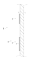
- 1 is a cross-sectional view of a photodiode according to a first embodiment of the present invention.
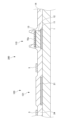
- 2 is a cross-sectional view of a photosensing portion according to the first embodiment of the present invention.
- 5A to 5C are cross-sectional views of a manufacturing process of the photosensing unit according to the first embodiment of the present invention.
- 5A to 5C are cross-sectional views of a manufacturing process of the photosensing unit according to the first embodiment of the present invention.
- 5A to 5C are cross-sectional views illustrating a manufacturing process of the photosensing unit according to the first embodiment of the present invention
- 5A to 5C are cross-sectional views illustrating a manufacturing process of the photosensing unit according to the first embodiment of the present invention.
- 5A to 5C are cross-sectional views illustrating a manufacturing process of the photosensing unit according to the first embodiment of the present invention.
- 5A to 5C are cross-sectional views illustrating a manufacturing process of the photosensing unit according to the first embodiment of the present invention.
- 5A to 5C are cross-sectional views of a manufacturing process of the photosensing unit according to the first embodiment of the present invention.
- 5A to 5C are cross-sectional views illustrating a manufacturing process of the photosensing unit according to the first embodiment of the present invention.
- FIG. 11 is a plan view of a photosensing portion according to a first modified example of the present invention.
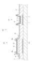
- FIG. 11 is a cross-sectional view of a photosensing portion according to a first modified example of the present invention.
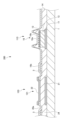
- FIG. 11 is a cross-sectional view of a photosensing portion according to a second embodiment of the present invention.
- 10A to 10C are cross-sectional views of a manufacturing process of a photosensing unit according to a second embodiment of the present invention.
- 10A to 10C are cross-sectional views of a manufacturing process of a photosensing unit according to a second embodiment of the present invention.
- 10A to 10C are cross-sectional views of a manufacturing process of a photosensing unit according to a second embodiment of the present invention.
- 10A to 10C are cross-sectional views of a manufacturing process of a photosensing unit according to a second embodiment of the present invention.
- 10A to 10C are cross-sectional views of a manufacturing process of a photosensing unit according to a second embodiment of the present invention.
- FIG. 11 is a cross-sectional view of a photodiode according to a second modified example of the present invention.
- FIG. 13 is a plan view of a photodiode according to a third modified example of the present invention.
- FIG. 13 is a cross-sectional view of a photodiode according to a third modified example of the present invention.
- FIG. 13 is a cross-sectional view of a photodiode according to a fourth modified example of the present invention.
- FIG. 13 is a schematic diagram showing a relationship between a photodiode and a signal processing circuit according to a fourth modified example of the present invention.
- FIG. 13 is a cross-sectional view of a photodiode according to a fifth modified example of the present invention.
- FIG. 13 is a cross-sectional view of a photodiode according to a sixth modified example of the present invention.
- FIG. 13 is a cross-sectional view of a photodiode according to a seventh modified example of the present invention.
- FIG. 13 is an overall circuit diagram of a two-dimensional photosensor according to an eighth modified example of the present invention.
- FIG. 13 is a plan view of a photosensing portion according to an eighth modified example of the present invention.
- FIG. 13 is a cross-sectional view of a photosensing portion according to an eighth modified example of the present invention.
- FIG. 13 is an overall circuit diagram of a two-dimensional photosensor according to a ninth modified example of the
- the two-dimensional photosensor 100 according to the first embodiment of the present invention will be described below with reference to the drawings.
- the same components are given the same reference numerals.
- a, b, etc. are added to the reference numerals.
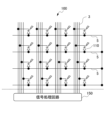
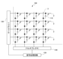
- (Embodiment 1) 1 is an overall circuit diagram of a two-dimensional photosensor 100 according to a first embodiment of the present invention.
- the two-dimensional photosensor 100 includes a photosensing section 200, a gate driver 130, a scanning electrode 2, a signal readout electrode 3, a multiplexer 140, and a signal processing circuit 150.
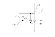
- the photosensing section 200 includes a photodiode 110 and a readout circuit 120.
- the photodiode 110 receives external light L, which is light from the outside, and outputs a current.
- the readout circuit 120 has a signal readout circuit thin film transistor 121.
- the gate driver 130 has a gate signal output terminal. The gate signal output terminal is connected to each of the multiple scanning electrodes 2.
- the scanning electrodes 2 sequentially transmit signals from the gate driver 130 to the readout circuit 120.
- one end functioning as an anode electrode is connected to the reference voltage unit 4, and the other end functioning as a cathode electrode is connected to the readout circuit 120.
- the readout circuit 120 receives a signal from the gate driver 130 and reads out the photocurrent of the photodiode 110.
- the readout circuit 120 transmits the read photocurrent of the photodiode 110 to the signal readout electrode 3.
- the signal readout electrode 3 transmits the transmitted photocurrent to the multiplexer 140.
- the multiplexer 140 sequentially transmits signals from the multiple signal readout electrodes 3 to the signal processing circuit 150.
- the signal processing circuit 150 processes the photocurrent output by the photodiode 110 as a signal. If the photocurrent is large, the signal processing circuit 150 determines that light is being irradiated, and calculates the incident light intensity based on the amount of photocurrent.
- the gate driver 130 outputs voltages sequentially to the multiple scanning electrodes 2, i.e., scanning electrodes 2a, ..., scanning electrodes 2n, scanning electrodes 2n+1, .... That is, the scanning electrodes 2 are scanned.
- the readout circuits 120 operate sequentially in conjunction with the scanning.
- a plurality of readout circuits 120 are connected to each scanning electrode 2.
- the readout circuit 120 connected to the scanning electrode 2a reads out the photocurrent of the photodiode 110 when the scanning electrode 2a is scanned and transmits it to the signal processing circuit 150.
- the readout circuit 120 connected to the scanning electrode 2n reads out the photocurrent of the photodiode 110 when the scanning electrode 2n is scanned and transmits it to the signal processing circuit 150.
- FIG. 2 is a diagram showing an example of the characteristics of the photodiode 110.
- the photodiode 110 according to this embodiment is a Schottky diode.
- the horizontal axis indicates the voltage applied to the photodiode 110.
- the positive direction of the horizontal axis indicates a state in which a voltage is applied to the photodiode 110 in the forward direction.
- the negative direction of the horizontal axis indicates a state in which a voltage is applied to the photodiode 110 in the reverse direction.
- the vertical axis indicates the photocurrent output by the photodiode 110.
- the unit is amperes.
- the illuminance of the external light L irradiating the photodiode 110 was changed from 0 lux (lux) to 7006 lux.
- the experimental results in which the illuminance is set to 0 lux indicate the experimental results in a darkroom.
- FIG. 2 shows that a current flows when a voltage is applied in the reverse direction, that is, when a voltage is applied in the negative direction of the horizontal axis in FIG. 2. The higher the illuminance, the larger the current that flows.
- a minute dark current of almost 0 amperes flows when the illuminance is 0 lux
- about 0.8 ⁇ 10 ⁇ 9 amperes flows when the illuminance is 1802 lux
- about 2 ⁇ 10 ⁇ 9 amperes flows when the illuminance is 3672 lux
- about 3.9 ⁇ 10 ⁇ 9 amperes flows when the illuminance is 7006 lux.
- Figure 3 is a schematic diagram showing the output signal from the gate driver 130, the reset signal, and the output voltage of the signal processing circuit 150.
- the horizontal axis represents time.
- Figure 3(a) shows the output voltage from the gate driver 130 to the scanning electrode 2n in the nth row.
- Figure 3(b) shows the output voltage from the gate driver 130 to the scanning electrode 2n+1 in the n+1th row.
- Figure 3(c) shows the reset state of the reset switch 152 of the signal processing circuit 150 in the mth column shown in Figure 1.
- Figure 3(d) shows the output voltage Vout of the signal processing circuit 150 based on the photodiode 110 in the mth column and nth row.
- an ON voltage (e.g., +15V) is applied to the nth row scanning electrode 2 at time t1, as shown in FIG. 3(a).
- An ON voltage is applied to the scanning electrode 2 shown in FIG. 1, the gate of the signal readout circuit thin-film transistor 121 opens, and the source-drain electrode of the signal readout circuit thin-film transistor 121 becomes conductive.
- the switch of the signal readout circuit thin-film transistor 121 as a switch is turned ON.
- an OFF voltage (e.g., -5V) is applied to the n+1th row scanning electrode 2n+1, as shown in FIG. 3(b).
- the signal processing circuit 150 has an operational amplifier 151 as shown in FIG. 1.
- the signal processing circuit 150 applies a reference voltage (see FIG. 1, Vref, for example, +1.5 V) to the signal readout electrode 3 via the operational amplifier 151.
- Vref a reference voltage
- the reset switch 152 of the signal processing circuit 150 is turned on.
- the operational amplifier 151 is reset.
- the detection voltage of the signal processing circuit 150 decreases from time t1 to time t2. That is, the voltage based on the photodiode 110 is reset.
- the time between time t1 and time t2 is, for example, 160 microseconds.
- time t2 as shown in FIG.
- the reset switch 152 of the signal processing circuit 150 is turned OFF.
- the reference voltage is applied to the photodiode 110 as a reverse bias voltage.
- an ON voltage is applied to the scanning electrode 2 of the nth row until time t3.
- a photocurrent flows through the photodiode 110 due to the external light L, and the voltage of the signal readout electrode 3 tends to decrease.
- the output voltage (Vout) of the signal processing circuit 150 gradually increases from time t2 to time t3, as shown in FIG. 3(d).
- an OFF voltage is applied to the scanning electrode 2 of the nth row, as shown in FIG.
- the output voltage (Vout) of the signal processing circuit 150 reaches a maximum at time t3, as shown in FIG. 3(d).
- the voltage at time t3 is detected as a voltage representing the intensity of the light incident on the photodiode 110.
- an ON voltage is applied to the scanning electrode 2 in the n+1th row.
- the intensity of light incident on the photodiode 110 is detected in the same manner for the n+1th row and above.
- the above scanning is performed from the first row to the last row, and after the last row, scanning returns to the first row.
- the intensity of the incident light is detected from the first column to the last column of the first row, and further to the last column of the last row. That is, the incident light intensity is detected in a two-dimensional plane.
- the operation of the two-dimensional photosensor 100 has been described above as the operation of an electronic circuit.
- the structure of the two-dimensional photosensor 100 according to this embodiment will now be described.
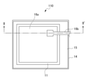
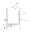
- FIG. 4 is a plan view of the photosensing section 200.
- the photosensing section 200 has a photodiode 110 and a readout circuit 120.
- the readout circuit 120 has a signal readout circuit thin-film transistor 121.
- the photodiode 110 has a first metal electrode 11, a first semiconductor layer 12, and a first transparent electrode 16.
- the signal readout circuit thin-film transistor 121 has a first gate electrode 21a, a third insulating layer 24 (not shown in FIG. 4), a second semiconductor layer 22, a transparent source electrode 26a, and a transparent drain electrode 26b.
- the first metal electrode 11 extends linearly in the left-right direction of the two-dimensional photosensor 100.
- the first metal electrode 11 is connected to the reference voltage section 4 shown in FIG. 1 but not shown in FIG. 4.
- the first metal electrode 11 extends in a rectangular shape in the up-down direction in the photosensing section 200.
- the first semiconductor layer 12 is formed in an island shape on the first metal electrode 11.
- the first ohmic contact layer 13, not shown in FIG. 4 is formed in an island shape so as to cover the first semiconductor layer 12.
- the first insulating layer 14, not shown in FIG. 4, is arranged so as to cover the glass substrate 1 and a part of the first ohmic contact layer 13.
- the first transparent electrode 16 is arranged in a planar shape in contact with the first ohmic contact layer 13.
- the scanning electrode 2 extends, for example, in the left-right direction of the two-dimensional photosensor 100 and the left-right direction of the photosensing section 200.
- the scanning electrode 2 has an extension portion in a two-dimensional plane in the photosensing section 200.
- the signal readout circuit thin film transistor 121 has the extension portion of the scanning electrode 2 as the first gate electrode 21a.
- the signal readout circuit thin film transistor 121 has a planar third insulating layer 24 on the first gate electrode 21a.
- the signal readout circuit thin film transistor 121 has a second semiconductor layer 22 on the third insulating layer 24.
- the second semiconductor layer 22 is island-shaped.
- the signal readout circuit thin film transistor 121 may have an ohmic contact layer on the second semiconductor layer 22.
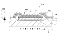
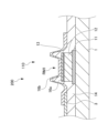
- FIG. 5 is a cross-sectional view of the photodiode 110 taken along line I-I' in FIG. 4.
- the photodiode 110 is disposed on a glass substrate 1.
- the glass substrate 1 may be a film substrate.
- the photodiode 110 has a laminate of a first metal electrode 11, a first semiconductor layer 12, a first ohmic contact layer 13, a first insulating layer 14, and a first transparent electrode 16.
- the constituent layers that are omitted in FIG. 4 are shown in FIG. 5.
- the glass substrate 1 is, for example, alkali-free glass, such as borosilicate glass.
- the glass substrate 1 has a thickness of, for example, 0.5 to 0.7 mm.
- the first metal electrode 11 is disposed on the glass substrate 1.
- the first metal electrode 11 has, for example, a substantially rectangular shape as shown in FIG. 4.
- the first metal electrode 11 is, for example, an alloy of molybdenum and tantalum. Other examples include low-resistance metals such as aluminum (Al) and copper (Cu).
- the first metal electrode 11 has a thickness of, for example, 200 nm.
- the first semiconductor layer 12 is disposed on the first metal electrode 11.
- the first semiconductor layer 12 has, for example, a substantially rectangular shape as shown in FIG. 4.
- the first semiconductor layer 12 is, for example, an amorphous silicon layer.
- the first semiconductor layer 12 has a thickness of, for example, 200 nm.
- the first ohmic contact layer 13 is disposed on the first semiconductor layer 12.
- the first ohmic contact layer 13 is, for example, an amorphous silicon layer doped with donor atoms as impurities.
- the amorphous silicon layer doped with donor atoms as impurities is referred to as an n+ amorphous silicon layer.
- the n+ amorphous silicon layer has a thickness of, for example, 50 nm.
- the first insulating layer 14 is disposed so as to cover the first metal electrode 11, the first semiconductor layer 12, and the first ohmic contact layer 13.
- the first insulating layer 14 is, for example, a silicon nitride (SiN) film.
- the first insulating layer 14 has a thickness of, for example, 400 nm.
- a part of the first insulating layer 14 is not disposed on the top of the first ohmic contact layer 13 in the insulating layer removal portion RM1.
- the first transparent electrode 16 is disposed on the first insulating layer 14. In particular, the first transparent electrode 16 is disposed so as to cover the top of the first ohmic contact layer 13 where the first insulating layer 14 is not disposed.
- the first transparent electrode 16 is, for example, a film of an oxide of an alloy of indium and titanium (ITO).
- examples of transparent electrodes include an oxide of an alloy of indium and zinc (IZO) and an oxide of aluminum and zinc (AlZn oxide).
- the first transparent electrode 16 has a thickness of, for example, 100 nm.
- the first transparent electrode 16 and the first ohmic contact layer 13 are in contact with each other and electrically connected.
- a Schottky barrier portion S is formed between the first metal electrode 11 and the first semiconductor layer 12.
- the first transparent electrode 16 the first ohmic contact layer 13, and the first semiconductor layer 12 are in ohmic contact, and no Schottky barrier is formed.
- the first metal electrode 11, the first semiconductor layer 12, the first ohmic contact layer 13, and the first transparent electrode 16 constitute a Schottky diode.
- a schematic diagram of the diode circuit is shown on the right side of Figure 5. As shown in this schematic diagram, a Schottky diode is realized in which the direction from the first metal electrode 11 to the first transparent electrode 16 is the forward direction.
- the Schottky barrier portion S occurs at the interface between the first metal electrode 11 and the first semiconductor layer 12. This allows the thickness of the first semiconductor layer 12 to be thin. However, if the layer is too thin, the electric field in the Schottky barrier portion will concentrate, increasing the leakage current. On the other hand, if the amorphous silicon layer is too thick, the resistance will increase and the photocurrent will decrease. In this embodiment, for example, an amorphous silicon layer with a thickness of 200 nm is disposed. The thickness of the amorphous silicon layer is preferably 50 nm or more and 500 nm or less.
- the amorphous silicon layer is thick, for example, about 1-2 microns. Light cannot pass through the amorphous silicon layer.
- the first semiconductor layer 12 made of amorphous silicon according to the present invention is thin, for example, 200 nm, so external light L passes through. The external light L reaches the Schottky barrier portion S over the entire surface of the first semiconductor layer 12 made of amorphous silicon.
- a photosensing portion 200 with a wide light receiving portion can be realized with a simple configuration.
- external light L is incident from the side where the first transparent electrode 16 is arranged, that is, from the upper direction of the paper in FIG. 5.
- the first transparent electrode 16 and the first insulating layer 14 have high optical transparency.
- the external light L passes through the first transparent electrode 16 and the first insulating layer 14.
- the external light L is incident on the interface between the first semiconductor layer 12 and the first metal electrode 11, where a Schottky barrier is present.
- the external light L is absorbed by the first semiconductor layer 12.
- the external light L is incident from the side of the first transparent electrode 16 toward the first semiconductor layer 12. Then, the charge carrier pairs of the Schottky barrier are released.
- the free charge carriers provide a photocurrent.
- FIG. 6 is a cross-sectional view of the photosensing unit 200 corresponding to line I-I' in FIG. 4.
- the photosensing unit 200 has a photodiode 110 and a readout circuit 120.
- the photodiode 110 shown in FIG. 6 is a modified version of the photodiode 110 shown in FIG. 5, and the first transparent electrode 16 is formed in two layers.
- the two layers of the first transparent electrode 16 are distinguished and denoted as the lower first transparent electrode 16a and the upper first transparent electrode 16b, respectively.
- the photodiode 110 has a first metal electrode 11, a first semiconductor layer 12, a first ohmic contact layer 13, a first transparent electrode 16, a first insulating layer 14, and a second insulating layer 17. Compare with the photodiode 110 shown in FIG. 5.
- the photodiode 110 shown in FIG. 6 and the photodiode 110 shown in FIG. 5 have in common the configuration in which the first metal electrode 11, the first semiconductor layer 12, and the first ohmic contact layer 13 are arranged in this order on the glass substrate 1.
- the lower first transparent electrode 16a is arranged on the entire surface of the first ohmic contact layer 13.
- the first insulating layer 14 is formed on the first ohmic contact layer 13, and an insulating layer removal portion RM1 is provided as a region where a part of the first insulating layer 14 is not formed.
- the upper first transparent electrode 16b is provided on the first insulating layer 14.
- the upper first transparent electrode 16b is arranged to cover the insulating layer removed portion RM1.
- the upper first transparent electrode 16b is arranged to cover the insulating layer removed portion RM1, which is the same as the first transparent electrode 16 in the photodiode 110 of FIG. 5, in which the first transparent electrode 16 is arranged to cover the insulating layer removed portion RM1.
- the manufacturing method will be described later, but in the patterning of the first insulating layer 14, in the configuration of FIG. 5, the first ohmic contact layer 13 may also be patterned.
- the lower first transparent electrode 16a plays the role of a stopper, so that the first ohmic contact layer 13 is less likely to be patterned.
- the configuration of FIG. 5 is simple and shows a basic configuration. The configuration of FIG. 6 is more reliable.
- a second insulating layer 17 is arranged on the upper first transparent electrode 16b.
- the readout circuit 120 will be described with reference to Figures 4 and 6.
- the readout circuit 120 has a signal readout circuit thin-film transistor 121 and a signal readout electrode 3.
- the signal readout circuit thin-film transistor 121 has a second metal electrode 21, a third insulating layer 24, a second semiconductor layer 22, a second transparent electrode 26, a fourth insulating layer 27, a third metal electrode 28, and a third transparent electrode 29.
- the second metal electrode 21 is disposed on the glass substrate 1.
- the second metal electrode 21 and the first metal electrode 11 are formed at the same time as described below, and are composed of the same layer.
- the same layer includes layers formed at the same time, layers of substantially the same thickness, and layers of the same material.
- This process is a metal electrode film formation process in which the first metal electrode 11 and the second metal electrode 21 are formed at the same time.
- the second metal electrode 21 is, for example, an alloy of molybdenum and tantalum.
- the second metal electrode 21 has a thickness of, for example, 200 nm.
- the second metal electrode 21 also constitutes the scanning electrode 2 shown in FIG. 4. As shown in FIG. 4, a part of the scanning electrode 2 extends in a branch shape and constitutes a part of the signal readout circuit thin film transistor 121. This extended part constitutes the first gate electrode 21a of the signal readout circuit thin film transistor 121.
- the third insulating layer 24 is disposed on the second metal electrode 21 so as to cover the second metal electrode 21.
- the third insulating layer 24 is, for example, a silicon nitride (SiN) film.
- the third insulating layer 24 has a thickness of, for example, 400 nm.
- the third insulating layer 24 and the first insulating layer 14 are formed simultaneously as described below, and are composed of the same layer. This process is an insulating layer formation process in which the first insulating layer 14 and the third insulating layer 24 are formed simultaneously.
- the signal readout electrode 3 is provided on the third insulating layer 24.
- the signal readout electrode 3 is a metal electrode such as chromium (Cr), aluminum (Al), or titanium (Ti). As shown in FIG. 4, the signal readout electrode 3 extends in the vertical direction of the two-dimensional photosensor 100. A part of the signal readout electrode 3 extends in a branch-like manner in the horizontal direction, for example, to the right in FIG. 4.
- the extended part of the signal readout electrode 3 constitutes a part of the readout circuit 120, as shown at the left end of FIG. 6.
- the extended part of the signal readout electrode 3 overlaps and is electrically connected to the second transparent electrode 26 described later, and constitutes the metal source electrode 3a and the metal drain electrode 3b.
- the metal source electrode 3a and the metal drain electrode 3b have the function of lowering the resistance of the transparent source electrode 26a and the transparent drain electrode 26b of the second transparent electrode 26, whereas the second transparent electrode 26 alone has a high resistance.
- the second transparent electrode 26 is disposed on the third insulating layer 24 and on the extended portion of the scanning electrode 2, i.e., the first gate electrode 21a, so that a portion of the electrode overlaps the extended portion.
- the second transparent electrode 26 is, for example, an ITO film.
- the second transparent electrode 26 has a thickness of, for example, 100 nm.
- the second transparent electrode 26 constitutes the transparent source electrode 26a and the transparent drain electrode 26b of the signal readout circuit thin film transistor 121.
- the transparent drain electrode 26b which is a part of the second transparent electrode 26, is electrically connected to the first transparent electrode 16.
- the second transparent electrode 26 and the first transparent electrode 16 are formed at the same time and are composed of the same layer. This process is a transparent electrode film formation process in which the first transparent electrode 16 and the second transparent electrode 26 are formed at the same time.
- the second semiconductor layer 22 is arranged in an island shape as shown in FIG. 4.
- the second semiconductor layer 22 is arranged on the third insulating layer 24 and overlapping the second transparent electrode 26 as shown in FIG. 6.
- the second semiconductor layer 22 is composed of a transparent oxide semiconductor (hereinafter, IGZO) composed of, for example, indium (In), gallium (Ga), zinc (Zn), and oxygen (O).
- IGZO transparent oxide semiconductor
- the fourth insulating layer 27 is disposed on the second semiconductor layer 22 and the second transparent electrode 26 so as to cover them.
- the fourth insulating layer 27 and the second insulating layer 17 may be formed simultaneously as described below, and are composed of the same layer. This process is an insulating layer deposition process in which the second insulating layer 17 and the fourth insulating layer 27 are formed simultaneously.
- the third metal electrode 28 is disposed at a position overlapping the second metal electrode 21 when viewed in a direction perpendicular to the glass substrate 1, i.e., from the top of the paper.
- the second metal electrode 21 functions as the first gate electrode 21a
- the third metal electrode 28 functions as the second gate electrode 21b.
- the first gate electrode 21a and the second gate electrode 21b function as the gate electrodes of the signal readout circuit thin film transistor 121, and control the ON/OFF of the signal readout circuit thin film transistor 121 as a switch.
- the third transparent electrode 29 is disposed at a position overlapping the third metal electrode 28 when viewed in a direction perpendicular to the glass substrate 1, i.e., from the top of the paper.
- FIG. 7 to FIG. 14 are cross-sectional views of the photosensing unit 200 at each manufacturing step.
- the photosensing unit 200 has a photodiode 110 and a readout circuit 120.
- the photodiode 110 is formed, and then the signal readout circuit thin-film transistor 121 having IGZO as a semiconductor layer is formed, as will be described in detail later. It is preferable to form them in this order. If manufactured from IGZO, hydrogen will be added to the IGZO from the amorphous silicon when the photodiode 110 is created, and it may be difficult to obtain good characteristics for the IGZO thin-film transistor.
- a first metal electrode 11 and a second metal electrode 21 are simultaneously formed on a glass substrate 1.
- This process is a metal electrode film formation process in which a first metal electrode 11 and a second metal electrode 21 are simultaneously formed.
- This formation process is one of the processes in which layers constituting a photodiode 110 and a signal readout circuit thin film transistor 121 are simultaneously formed or formed.
- a metal thin film of chromium, aluminum, titanium, or the like is formed by sputtering.
- the metal thin film has a thickness of, for example, approximately 200 nm. Photoresist is applied to this thin film.
- a pattern of the metal thin film is formed by photolithography.
- the metal thin film in the portion not covered by the resist is etched by a chlorine-based dry etching method.
- the first metal electrode 11 has, for example, the pattern shown in the plan view of FIG. 4.
- the second metal electrode 21 has, for example, the pattern shown in the plan view of FIG. 4.
- the first semiconductor layer 12, the first ohmic contact layer 13, and the lower first transparent electrode 16a are continuously stacked to form a laminate.
- the first semiconductor layer 12 is, for example, an amorphous silicon (a-Si) layer.
- the first ohmic contact layer 13 is, for example, an n+ amorphous silicon (n+a-Si) layer.
- the lower first transparent electrode 16a is, for example, ITO.
- the laminate is patterned into islands.
- the island pattern of the laminate overlaps with the island pattern of the first metal electrode 11, for example, as shown in FIG. 4, and has an area smaller than that of the island pattern of the first metal electrode 11.
- the first insulating layer 14 and the third insulating layer 24 are simultaneously formed.
- the first insulating layer 14 and the third insulating layer 24 are composed of the same layer.
- This process is an insulating layer forming process for simultaneously forming the insulating layer of the photodiode 110 and the insulating layer of the signal readout circuit thin film transistor 121.
- the first insulating layer 14 and the third insulating layer 24 are, for example, SiN films.
- the SiN film is formed, for example, by plasma CVD or the like.
- the SiN film is patterned, for example, by SF6 -based dry etching. In particular, the patterning is performed so that a part of the lower first transparent electrode 16a is exposed.
- the lower first transparent electrode 16a functions as an etching stopper. Since the etching stops at the first transparent electrode 16a, the n+ amorphous silicon is not etched away. The configuration shown in FIG. 5 without the first transparent electrode 16a is also effective. In the absence of the lower first transparent electrode 16a, precise control of the etching end point of the SF6 dry etching is required. Since there is no etching stopper, there is a possibility that the n+ amorphous silicon will be etched away. In order to prevent the n+ amorphous silicon from being etched away, it is necessary to precisely control the etching end point.
- the signal readout electrode 3 is formed.
- the signal readout electrode 3 is, for example, a metal thin film of chromium (Cr), aluminum (Al), titanium (Ti), or the like. After the metal thin film is formed, it is patterned by chlorine-based dry etching.
- the first transparent electrode 16b in the upper layer is formed and at the same time the second transparent electrode 26 is formed.
- the first transparent electrode 16b in the upper layer and the second transparent electrode 26 are composed of the same layer. This process is a transparent electrode film formation process in which the first transparent electrode 16b in the upper layer and the second transparent electrode 26 are simultaneously formed.
- the second transparent electrode 26 constitutes the transparent source electrode 26a and the transparent drain electrode 26b of the signal readout circuit thin film transistor 121.
- the transparent drain electrode 26b is continuous with and electrically connected to the first transparent electrode 16b in the upper layer of the photodiode 110.
- the second semiconductor layer 22 is composed of, for example, an IGZO layer.
- the IGZO layer is formed by a sputtering method using, for example, an oxide semiconductor target containing In, Ga, and Zn.
- the IGZO film is etched using, for example, an organic acid such as citric acid or oxalic acid as an etchant.
- the second insulating layer 17 and the fourth insulating layer 27 are formed simultaneously.
- the second insulating layer 17 and the fourth insulating layer 27 are composed of the same layer.
- This process is an insulating layer deposition process in which the second insulating layer 17 and the fourth insulating layer 27 are formed simultaneously.
- the second insulating layer 17 and the fourth insulating layer 27 are, for example, silicon oxide (SiO2), and are formed, for example, by a plasma CVD method.
- the third metal electrode 28 is a metal electrode such as chromium (Cr), aluminum (Al), or titanium (Ti).
- the third metal electrode 28 functions as the second gate electrode 21b in the signal readout circuit thin film transistor 121. This configuration has been known as a double gate configuration.
- the third metal electrode 28 assists the second metal electrode 21 to function as the first gate electrode 21a.
- the third transparent electrode 29 covers the third metal electrode 28 and has the function of preventing deterioration of the third metal electrode 28.
- the first semiconductor layer 12 is made of amorphous silicon
- the second semiconductor layer 22 is made of IGZO, which are different from each other.
- the first semiconductor layer 12 and the second semiconductor layer 22 are also different in the first modification.
- the layers in which the components of the photodiode 110 are formed are different.
- FIGS. 15 and 16 FIG. 15 is a plan view of a photosensing section 200 according to the first modification.
- FIG. 16 is a cross-sectional view of the photosensing section 200 according to the first modification.
- the first metal electrode 11 is formed in the same layer as the signal readout electrode 3.
- This process is a metal electrode film formation process in which the first metal electrode 11 and the signal readout electrode 3 are formed simultaneously.
- FIG. 15 the first metal electrode 11 that determines the reference voltage Vb of the photodiode 110 runs in the left-right direction of the figure, parallel to the scanning electrode 2. This is because the first metal electrode 11 is formed in the same layer as the scanning electrode 2.
- FIG. 15 showing the first modification the first metal electrode 11 is arranged in the up-down direction of the figure, parallel to the signal readout electrode 3.
- the first metal electrode 11 is arranged in parallel to the signal readout electrode 3 so that the first metal electrode 11 and the signal readout electrode 3 do not intersect. This is because the first metal electrode 11 is formed in the same layer as the signal readout electrode 3.
- a reference voltage Vb for example, minus 1 V, is applied to the first metal electrode 11.
- the second metal electrode 21 is disposed on the glass substrate 1. As shown in FIG. 15, the second metal electrode 21 extends in a branch-like manner from the scanning electrode 2, and functions as the first gate electrode 21a of the signal readout circuit thin film transistor 121.
- the second metal electrode 21 is made of, for example, a laminate of titanium, aluminum, and titanium, aluminum, molybdenum, copper, etc.
- the first insulating layer 14 and the third insulating layer 24 are formed simultaneously.
- This process is an insulating layer deposition process in which the first insulating layer 14 and the third insulating layer 24 are formed simultaneously.
- the third insulating layer 24 is composed of, for example, silicon nitride (SiN).
- the third insulating layer 24 has a thickness of, for example, 400 nm.
- the first metal electrode 11 is formed on the first insulating layer 14 (the same layer as the third insulating layer 24), and at the same time, the signal readout electrode 3 of the signal readout circuit thin film transistor 121 is formed on the third insulating layer 24.
- the first metal electrode 11 and the signal readout electrode 3 are composed of the same layer.
- This process is a metal electrode film formation process in which the first metal electrode 11 and the signal readout electrode 3 are formed simultaneously.
- the first metal electrode 11 extends linearly vertically and has a rectangular extension.
- the signal readout electrode 3 has an extension as shown in FIG. 15. The extension does not contact the second semiconductor layer 22 described later, and is disposed close to the channel portion of the second semiconductor layer 22.
- an alloy of molybdenum and tantalum MoTa
- MoTa molybdenum and tantalum
- the fourth transparent electrode 18 is formed on the first metal electrode 11 so as to cover the first metal electrode 11.
- the second transparent electrode 26 is formed at the same time.
- This process is a transparent electrode film formation process in which the fourth transparent electrode 18 and the second transparent electrode 26 are formed at the same time.
- the fourth transparent electrode 18 and the second transparent electrode 26 are, for example, ITO.
- the fourth transparent electrode 18 and the second transparent electrode 26, the first metal electrode 11 and the signal readout electrode 3 are patterned by a wet process or a dry process using, for example, hydrochloric acid or oxalic acid.
- the second transparent electrode 26 is patterned to form a transparent source electrode 26a and a transparent drain electrode 26b.
- the first semiconductor layer 12, the first ohmic contact layer 13, and the lower first transparent electrode 16a are formed in sequence and patterned together into an island shape.
- the first semiconductor layer 12 is amorphous silicon
- the first ohmic contact layer 13 is an n+ amorphous silicon layer
- the lower first transparent electrode 16a is ITO.
- a chlorine-based dry etching method is used for patterning.
- the lower first transparent electrode 16a functions as a so-called etching stopper that prevents the first ohmic contact layer 13 from being etched.
- the second semiconductor layer 22 has, for example, IGZO.
- the IGZO layer is formed by a sputtering method using, for example, an oxide semiconductor target containing In, Ga, and Zn.
- the IGZO film is etched using, for example, an organic acid such as citric acid or oxalic acid as an etchant.
- the second insulating layer 17 is formed so as to cover the lower first transparent electrode 16a. A part of the second insulating layer 17 is removed above the lower first transparent electrode 16a. Here, the lower first transparent electrode 16a prevents the etching of the second insulating layer 17 from eroding the first ohmic contact layer 13.
- the fourth insulating layer 27 is formed at the same time as the second insulating layer 17.
- the fourth insulating layer 27 and the second insulating layer 17 are composed of the same layer. This process is an insulating layer deposition process in which the second insulating layer 17 and the fourth insulating layer 27 are formed at the same time.
- the second insulating layer 17 and the fourth insulating layer 27 are, for example, silicon oxide (SiOx).
- a part of the fourth insulating layer 27 is removed at the portion constituting the transparent drain electrode 26b. The portion from which the fourth insulating layer 27 has been removed functions as the first contact hole portion C1.
- the third metal electrode 28 is formed and patterned.
- the third metal electrode 28 is, for example, an alloy of molybdenum and tantalum (MoTa).
- MoTa molybdenum and tantalum
- the third metal electrode 28 is patterned so as to overlap the first gate electrode 21a in a plan view, and functions as the second gate electrode 21b.
- the upper first transparent electrode 16b is formed and patterned so as to cover the lower first transparent electrode 16a and the first contact hole portion C1.
- the upper first transparent electrode 16b is formed simultaneously with the third transparent electrode 29.
- This process is a transparent electrode film formation process in which the upper first transparent electrode 16b and the third transparent electrode 29 are formed simultaneously.
- the upper first transparent electrode 16b is electrically connected to the transparent drain electrode 26b through the first contact hole portion C1.
- the photocurrent generated by the photodiode 110 reaches the transparent drain electrode 26b from the first transparent electrode 16 through the first contact hole C1, and then reaches the transparent source electrode 26a as the first gate electrode 21a and the second gate electrode 21b are turned on. From the transparent source electrode 26a, the signal is transmitted through the signal readout electrode 3 to the signal processing circuit 150 shown in FIG. 1.
- the second gate electrode 21b is electrically connected to the first gate electrode 21a.
- the second gate electrode 21b cooperates with the first gate electrode 21a to enhance the switching function of the signal readout circuit thin film transistor 121.
- a configuration in which only the second gate electrode 21b is formed and the first gate electrode 21a does not exist is also possible.
- This configuration is a top gate only configuration.
- IGZO is suitable for the second semiconductor layer 22. This is because IGZO has high mobility.
- FIG. 17 is a cross-sectional view of the photosensing section 200 according to the second embodiment.
- FIGS. 18 to 24 are cross-sectional views of the photosensing section 200 in each manufacturing process.
- the photosensing section 200 has a photodiode 110 and a readout circuit 120.
- the readout circuit 120 has a signal readout circuit thin-film transistor 121.
- the photodiode 110 has a Schottky diode having a Schottky barrier section S.
- the Schottky diode is the photodiode 110 that responds to external light L.
- the signal readout circuit thin-film transistor 121 is a channel-etch type thin-film transistor.
- the photodiode 110 has a first metal electrode 11, a first insulating layer 14, a first semiconductor layer 12, a first ohmic contact layer 13, a first transparent electrode 16, and a second insulating layer 17.
- a Schottky barrier portion S appears at the interface between the first metal electrode 11 and the first semiconductor layer 12.
- a Schottky diode is formed with the forward direction being from the first metal electrode 11 to the first transparent electrode 16.
- the glass substrate 1 is, for example, alkali-free glass, such as borosilicate glass.
- the glass substrate 1 has a thickness of, for example, 0.5 to 0.7 mm.
- the first metal electrode 11 is disposed on the glass substrate 1.
- the first metal electrode 11 has, for example, a substantially rectangular shape.
- the first metal electrode 11 is, for example, an alloy of molybdenum and tantalum.
- the first metal electrode 11 has a thickness of, for example, 200 nm.
- the first insulating layer 14 is disposed so as to cover the first metal electrode 11 except for the insulating layer removal portion RM1.
- the film formation process will be described in detail later, but after the first insulating layer 14 is formed so as to cover the first metal electrode 11, a portion of it is removed at the insulating layer removal portion RM1 above the first metal electrode 11.
- the first insulating layer 14 is, for example, a silicon nitride/silicon oxide (SiN/SiO2) film.
- the first insulating layer 14 has a thickness of, for example, 400 nm.
- the first semiconductor layer 12 is disposed on the first metal electrode 11.
- the first semiconductor layer 12 has, for example, a substantially rectangular shape.
- the first semiconductor layer 12 is, for example, an amorphous silicon layer.
- the first semiconductor layer 12 has a thickness of, for example, 200 nm.
- the first ohmic contact layer 13 is disposed on the first semiconductor layer 12.
- the first ohmic contact layer 13 is, for example, an n+ amorphous silicon layer.
- the n+ amorphous silicon layer has a thickness of, for example, 50 nm.
- the first transparent electrode 16 is disposed so as to cover the first insulating layer 14 and the first ohmic contact layer 13.
- the first transparent electrode 16 is, for example, a film of an oxide of an alloy of indium and titanium (ITO).
- the first transparent electrode 16 has a thickness of, for example, 100 nm.
- the first transparent electrode 16 and the first ohmic contact layer 13 are in contact with each other and are electrically connected.
- the second insulating layer 17 is disposed so as to cover the first transparent electrode 16.
- a Schottky barrier portion S is formed between the first metal electrode 11 and the first semiconductor layer 12.
- the first transparent electrode 16 the first ohmic contact layer 13, and the first semiconductor layer 12 are in ohmic contact, and no Schottky barrier is formed.
- the first metal electrode 11, the first semiconductor layer 12, the first ohmic contact layer 13, and the first transparent electrode 16 constitute a Schottky diode.
- a schematic diagram of the diode circuit is shown on the right side of Figure 17. As shown in this schematic diagram, a Schottky diode is realized in which the forward direction is from the first metal electrode 11 to the first transparent electrode 16.
- the Schottky barrier portion S occurs at the interface between the first metal electrode 11 and the first semiconductor layer 12. Therefore, the thickness of the first semiconductor layer 12 does not affect the appearance of the Schottky barrier. Therefore, the thickness of the first semiconductor layer 12 can be made thin.
- an amorphous silicon layer having a thickness of 200 nm is disposed.
- the thickness of the amorphous silicon layer is preferably 50 nm or more and 500 nm or less.
- the amorphous silicon layer is thick, for example, about 1 to 2 microns.
- the photodiode 110 can realize a photosensing portion 200 with a wide light receiving portion with a simple configuration.
- external light L is incident from the side where the first transparent electrode 16 is arranged.
- the first transparent electrode 16 and the second insulating layer 17 are highly transparent.
- the external light L passes through the first transparent electrode 16 and the second insulating layer 17.
- the external light L is incident on the interface between the first semiconductor layer 12 and the first metal electrode 11, where a Schottky barrier is present.
- the external light L is absorbed by the first semiconductor layer 12.
- the external light L is incident from the side of the first transparent electrode 16 toward the first semiconductor layer 12. Then, the charge carrier pairs of the Schottky barrier are released.
- the free charge carriers provide a photocurrent.
- the readout circuit 120 has a signal readout circuit thin film transistor 121 and a signal readout electrode 3.
- the signal readout circuit thin film transistor 121 has a second metal electrode 21, a third insulating layer 24, a second semiconductor layer 22, a second ohmic contact layer 23, a transparent source electrode 26a consisting of a metal source electrode 3a, a metal drain electrode 3b, a second transparent electrode 26, a transparent drain electrode 26b, and a fourth insulating layer 27.
- the source electrode has a configuration in which a metal source electrode 3a formed by extending in a branch shape from the signal readout electrode 3 and a transparent source electrode 26a consisting of the second transparent electrode 26 are stacked.
- the drain electrode has a configuration in which a metal drain electrode 3b formed in the same layer as the signal readout electrode 3 and a transparent drain electrode 26b consisting of the second transparent electrode 26 are stacked.
- the second metal electrode 21 is disposed on the glass substrate 1.
- the second metal electrode 21 and the first metal electrode 11 are formed simultaneously as described below, and are formed in the same layer. This process is a metal electrode film formation process in which the first metal electrode 11 and the second metal electrode 21 are formed simultaneously.
- the second metal electrode 21 is, for example, an alloy of molybdenum and tantalum.
- the second metal electrode 21 has a thickness of, for example, 200 nm.
- the second metal electrode 21 constitutes the scanning electrode 2 shown in FIG. 4. As shown in FIG. 4, a part of the scanning electrode 2 extends in a branch shape and constitutes a part of the signal readout circuit thin film transistor 121. This extended portion constitutes the first gate electrode 21a of the signal readout circuit thin film transistor 121.
- the third insulating layer 24 is disposed on the second metal electrode 21 so as to cover the second metal electrode 21.
- the third insulating layer 24 is, for example, a silicon nitride (SiN) film.
- the third insulating layer 24 has a thickness of, for example, 400 nm.
- the third insulating layer 24 and the first insulating layer 14 are formed simultaneously as described below, and are formed in the same layer. This process is an insulating layer formation process in which the first insulating layer 14 and the third insulating layer 24 are formed simultaneously.
- the second semiconductor layer 22 is arranged in an island shape to cover the first gate electrode 21a as shown in FIG. 4.
- the second semiconductor layer 22 is arranged on the third insulating layer 24 as shown in FIG. 17.
- An amorphous silicon layer is used as the second semiconductor layer 22, for example.
- a second ohmic contact layer 23 is provided on the amorphous silicon layer.
- the second ohmic contact layer 23 is composed of, for example, n+ amorphous silicon.
- This process is an ohmic contact layer film formation process in which the first ohmic contact layer 13 and the second ohmic contact layer 23 are formed simultaneously.
- the first semiconductor layer 12 and the second semiconductor layer 22 have a thickness of, for example, 200 nm.
- the n+ amorphous silicon layer constituting the first ohmic contact layer 13 and the second ohmic contact layer 23 has a thickness of, for example, 50 nm.
- the signal readout electrode 3 is provided on the third insulating layer 24 and the second ohmic contact layer 23.
- the signal readout electrode 3 is a metal electrode made of, for example, chromium (Cr), aluminum (Al), titanium (Ti), or the like. As shown in FIG. 4, the signal readout electrode 3 extends in the vertical direction of the two-dimensional photosensor 100. A portion of the signal readout electrode 3 extends in a branch-like manner in the horizontal direction, for example, to the right in FIG. 4. The extended portion of the signal readout electrode 3 constitutes a part of the readout circuit 120, as shown at the left end of FIG. 17.
- the second transparent electrode 26 is provided on the second ohmic contact layer 23 at two locations, sandwiching the first gate electrode 21a, as shown in FIG. 4.
- One functions as a transparent source electrode 26a of the signal readout circuit thin film transistor 121, and the other functions as a transparent drain electrode 26b of the signal readout circuit thin film transistor 121.
- the transparent drain electrode 26b which is a part of the second transparent electrode 26, is conductive with the first transparent electrode 16.
- the second transparent electrode 26 and the first transparent electrode 16 are formed simultaneously and are configured in the same layer. This process is a transparent electrode film formation process in which the first transparent electrode 16 and the second transparent electrode 26 are formed simultaneously. As shown in FIG.
- the transparent drain electrode 26b which is a part of the second transparent electrode 26, extends to become the first transparent electrode 16.
- the transparent drain electrode 26b is disposed on the first ohmic contact layer 13 so as to cover the first ohmic contact layer 13.
- the second transparent electrode 26 and the first transparent electrode 16 are, for example, films of an oxide of an alloy of indium and titanium (ITO).
- the first transparent electrode 16 and the second transparent electrode 26 have a thickness of, for example, 100 nm.
- the second ohmic contact layer 23, the metal source electrode 3a, the transparent source electrode 26a, the metal drain electrode 3b, and the transparent drain electrode 26b are patterned and arranged in two on the second semiconductor layer 22.
- the fourth insulating layer 27 is disposed on the second transparent electrode 26.
- the fourth insulating layer 27 is made of, for example, silicon nitride (SiN).
- SiN silicon nitride
- the second insulating layer 17 and the fourth insulating layer 27 are formed at the same time and are made of the same layer. This process is an insulating layer deposition process in which the second insulating layer 17 and the fourth insulating layer 27 are formed at the same time.
- External light L is incident on the photodiode 110, and a photocurrent is generated in the photodiode 110.
- An ON voltage e.g., 15 V
- the photocurrent is transmitted from the first transparent electrode 16 through the second transparent electrode 26, the transparent drain electrode 26b, the transparent source electrode 26a, and the signal readout electrode 3 to the signal processing circuit 150.
- FIG. 18 to FIG. 24 are cross-sectional views of the photosensing unit 200 taken along line I-I' in FIG. 4 at each manufacturing step.
- a first metal electrode 11 and a second metal electrode 21 are formed simultaneously on a glass substrate 1.
- a thin metal film of chromium, aluminum, titanium, or the like is formed by sputtering.
- the thin metal film has a thickness of, for example, approximately 200 nm.
- Photoresist is applied to this thin film.
- a pattern of the thin metal film is formed by photolithography. For example, the parts of the thin metal film that are not covered by the resist are etched by a chlorine-based dry etching method.
- the first metal electrode 11 has, for example, the pattern shown in the plan view of FIG. 4.
- the second metal electrode 21 has, for example, the pattern shown in the plan view of FIG. 4. This process is a metal electrode film formation process in which the first metal electrode 11 and the second metal electrode 21 are formed simultaneously.
- the first insulating layer 14 and the third insulating layer 24 are simultaneously formed.
- the first insulating layer 14 and the third insulating layer 24 are composed of the same layer.
- This process is an insulating layer forming process in which the first insulating layer 14 and the third insulating layer 24 are simultaneously formed.
- the first insulating layer 14 and the third insulating layer 24 are, for example, SiN films.
- the SiN film is formed, for example, by a plasma CVD method or the like.
- the SiN film is patterned, for example, by SF6 -based dry etching. In particular, the patterning is performed so that a part of the first metal electrode 11 is exposed.
- a second contact portion C2 is formed on the first metal electrode 11.
- the first semiconductor layer 12, the second semiconductor layer 22, the first ohmic contact layer 13, and the second ohmic contact layer 23 are continuously laminated to form a laminate.
- the first semiconductor layer 12 and the second semiconductor layer 22 are formed at the same time and are composed of the same layer.
- This process is a semiconductor layer deposition process in which the first semiconductor layer 12 and the second semiconductor layer 22 are formed at the same time.
- the first ohmic contact layer 13 and the second ohmic contact layer 23 are formed at the same time and are composed of the same layer.
- This process is an ohmic contact layer deposition process in which the first ohmic contact layer 13 and the second ohmic contact layer 23 are formed at the same time.
- the first semiconductor layer 12 and the second semiconductor layer 22 are, for example, amorphous silicon (a-Si) layers.
- the first ohmic contact layer 13 and the second ohmic contact layer 23 are, for example, n+ amorphous silicon (n+a-Si) layers.
- the stack is patterned into islands.
- the island pattern of the stack is shown in FIG. 4, for example.
- the first semiconductor layer 12 and the first ohmic contact layer 13 overlap the island pattern of the first metal electrode 11 and have an area equal to or smaller than that of the island pattern of the first metal electrode 11.
- the signal readout electrode 3 is, for example, a thin metal film made of chromium (Cr), aluminum (Al), titanium (Ti), or the like. After the thin metal film is formed, it is patterned by chlorine-based dry etching.
- the signal readout electrode 3 extends in a branch shape as shown in FIG. 4, and is also disposed on the second semiconductor layer and the second ohmic contact layer 23. The portion extending from the signal readout electrode 3 constitutes the metal source electrode 3a and metal drain electrode 3b of the signal readout circuit thin film transistor 121, as described below.
- the first transparent electrode 16 and the second transparent electrode 26 are formed simultaneously.
- the first transparent electrode 16 and the second transparent electrode 26 are composed of the same layer.
- This process is a transparent electrode film formation process in which the first transparent electrode 16 and the second transparent electrode 26 are formed simultaneously.
- the first transparent electrode 16 is arranged in an island shape on the first semiconductor layer 12 and the first ohmic contact layer 13 as shown in FIG. 4.
- a part of the portion arranged on the first gate electrode 21a by the second transparent electrode 26 and the signal readout electrode 3 is patterned.
- the patterning is performed, for example, by chlorine-based dry etching.
- the second transparent electrode 26 is arranged at two separate locations with the first gate electrode 21a made of the second metal electrode 21 sandwiched therebetween as shown in FIG. 4 and FIG. 22.
- One of the second transparent electrodes 26 functions as a transparent source electrode 26a, and the other second transparent electrode 26 functions as a transparent drain electrode 26b.
- the first transparent electrode 16 and the transparent drain electrode 26b, which is part of the second transparent electrode 26, are integrated and electrically conductive.
- the second ohmic contact layer 23 and a part of the second semiconductor layer 22 are patterned using the transparent source electrode 26a and the transparent drain electrode 26b made of the second transparent electrode 26 as a mask or resist.
- a channel etching portion CE is formed.
- SF4 -based dry etching is used. This method is generally called a channel etching method. Precise management of the etching end point of the SF6-based dry etching is required. Since there is no etching stopper, not only the n+ amorphous silicon but also the amorphous silicon may be etched away. It is necessary to manage the etching end point so that the amorphous silicon is not etched away.
- the second insulating layer 17 and the fourth insulating layer 27 are formed simultaneously.
- the second insulating layer 17 and the fourth insulating layer 27 are composed of the same layer.
- This process is an insulating layer deposition process in which the second insulating layer 17 and the fourth insulating layer 27 are formed simultaneously.
- the second insulating layer 17 and the fourth insulating layer 27 are, for example, silicon nitride (SiN), and are formed, for example, by a plasma CVD method.
- FIG. 25 is a cross-sectional view of a photodiode 110 according to a second modified example.
- a fifth insulating layer 15 is further disposed on the first insulating layer 14 disclosed in the above embodiment.
- the fifth insulating layer 15 is also a dielectric layer.
- the first insulating layer 14 is made of silicon nitride (SiN).
- the fifth insulating layer 15 is made of silicon oxide (SiO2).
- the fifth insulating layer 15 is formed on the outermost surface of the photodiode 110 opposite the glass substrate 1.
- the fifth insulating layer 15 has a function of reducing surface reflection.
- a low reflection structure is realized by phase difference adjustment (index matching).
- the fifth insulating layer 15 has a refractive index of 1.5 and a thickness of 90 nm, for example. This increases the amount of light reaching the Schottky barrier portion S, improving the sensitivity of the photodiode 110.
- FIG. 26 and 27 show an example of a photodiode 110 according to the third modification.
- FIG. 26 is a plan view.
- FIG. 27 is a cross-sectional view taken along the line II-II' shown in FIG. 26.
- the fifth insulating layer 15 is arranged wider than that in the second modification shown in FIG. 25.
- the fifth insulating layer 15 is transparent, the first transparent electrode 16b and the like are indicated by solid lines, not dotted lines.
- the fifth insulating layer 15 is made of, for example, silicon oxide (SiO2).
- the fifth insulating layer 15 is arranged so as to cover the first insulating layer 14 and the first transparent electrode 16 (the first transparent electrode 16b in the upper layer and the first transparent electrode 16a in the lower layer). Silicon nitride (SiN) and silicon oxide (SiO2) are arranged in a stacked manner except for the portion where the first transparent electrode 16b in the upper layer is formed.
- SiN silicon nitride
- SiO2 silicon oxide
- FIG. 28 is a cross-sectional view of the photodiode 110 according to the fourth modification taken along the II' cross-sectional line shown in FIG. 4.
- the first semiconductor layer 12 is laminated on the first metal electrode 11, and the first ohmic contact layer 13 is laminated on the first semiconductor layer 12.
- the first ohmic contact layer 13 is laminated on the first metal electrode 11, and the first semiconductor layer 12 is laminated on the first ohmic contact layer 13.
- the first transparent electrode 16a in the lower layer is laminated on the first semiconductor layer 12.
- the first insulating layer 14 is formed, and a part of the first transparent electrode 16a in contact with the first transparent electrode 16a in the lower layer is removed to form an insulating layer removed portion RM1.
- the first transparent electrode 16b in the upper layer is disposed to cover the insulating layer removed portion RM1.
- the first transparent electrode 16b in the upper layer and the first transparent electrode 16a in the lower layer are electrically connected.
- the materials constituting the first metal electrode 11, the first semiconductor layer 12, the first ohmic contact layer 13, the first insulating layer 14, and the first transparent electrode 16 are the same as those described in the above embodiment.
- the Schottky barrier portion S occurs at the interface between the first semiconductor layer 12 and the first transparent electrode 16a.
- the forward direction of the photodiode 110 is from the first transparent electrode 16 to the first metal electrode 11, as shown on the left in FIG. 28.
- a photodiode 110 is formed that is in the reverse direction to the drain electrode of the signal readout circuit thin film transistor 121.
- a reverse bias must be applied to the photodiode 110.
- the reference voltage Vb shown in FIG. 1 was -1V.
- the reference voltage Vb in the fourth modified example is, for example, +3V.
- the signal readout circuit thin film transistor 121 for the photodiode 110 it is preferable to use IGZO as in the first embodiment.
- the manufacturing process described in the first embodiment can be followed.
- the second embodiment uses amorphous silicon as the second semiconductor layer 22, similar to the fourth modification. However, the stacking order of the n+ amorphous silicon is different from that of the fourth modification.
- an inverted staggered thin film transistor is used. It is difficult to change the stacking order of the second semiconductor layer 22 and the second ohmic contact layer 23. For this reason, in the fourth modification, it is difficult to share the manufacturing process as in the second embodiment. In the fourth modification, it is preferable to follow the first embodiment.
- FIG. 30 is a cross-sectional view of a photodiode 110 according to the fifth modified example.
- the lower first transparent electrode 16a was disposed.
- the lower first transparent electrode 16a is not disposed.
- the lower first transparent electrode 16a functions as an etching stopper. Removal of the first insulating layer 14 does not lead to removal of the first semiconductor layer 12, for example, amorphous silicon.
- the first semiconductor layer 12 is partially etched.
- the upper part of the first semiconductor layer 12 is etched, and the first semiconductor layer 12 has a concave shape.
- the first ohmic contact layer 13 is, for example, n+ amorphous silicon, and its thickness is thin, for example, 50 nm.
- the lower first transparent electrode 16a is disposed as shown in FIG. 6.
- the first semiconductor layer 12, for example an amorphous silicon layer has a thickness of, for example, 200 nm.
- the first semiconductor layer 12 is thicker than the first ohmic contact layer 13. For this reason, as shown in Fig. 30, there is no high need for precise etching control to prevent the entire first semiconductor layer 12 from being etched.
- the fifth modification has an advantage that the lower first transparent electrode 16a shown in Fig. 28 is not required and the process is short, as shown in Fig. 30.
- (Sixth Modification) 31 is a cross-sectional view of a photodiode 110 according to the sixth modification.
- the photodiode 110 receives external light L incident from the opposite side of the glass substrate 1.
- the photodiode 110 according to the sixth modification receives external light L incident from the glass substrate 1 side.
- the first metal electrode 11 is made of a transparent electrode.
- the external light L is incident from the transparent first metal electrode 11 side toward the first semiconductor layer 12.
- the first metal electrode 11 is preferably, for example, AZO, which is zinc oxide doped with aluminum (Al).
- a zinc oxide (ZnO) transparent conductive film, GZO doped with gallium, or an ITO film may be adopted.
- the first semiconductor layer 12, the first ohmic contact layer 13, and the lower first transparent electrode 16a are stacked in this order on the first metal electrode 11, patterned, and arranged.
- the first insulating layer 14 is stacked and patterned.
- An insulating layer removal portion RM1 is formed on the lower first transparent electrode 16a.
- a fourth metal electrode 19 is arranged to cover the insulating layer removal portion RM1.
- the upper first transparent electrode 16b is formed on the fourth metal electrode 19.
- the first semiconductor layer 12 is, for example, an amorphous silicon layer.
- the first ohmic contact layer 13 is, for example, an n+ amorphous silicon layer.
- the lower first transparent electrode 16a and the upper first transparent electrode 16b are, for example, ITO layers.
- the fourth metal electrode 19 is, for example, chromium (Cr), aluminum (Al), titanium (Ti), etc.
- the fourth metal electrode 19 may be formed simultaneously with the metal source electrode 3a and the metal drain electrode 3b of the signal readout circuit thin film transistor 121 and may be configured in the same layer. This process is a metal electrode film formation process that simultaneously forms the fourth metal electrode 19, the metal source electrode 3a, and the metal drain electrode 3b.
- External light L incident from the side opposite to the glass substrate 1 is blocked by the fourth metal electrode 19.
- external light L incident from the glass substrate 1 side passes through the first metal electrode 11 and reaches the Schottky barrier section S formed at the interface between the first metal electrode 11 and the first semiconductor layer 12.
- the photodiode 110 receives the external light L and generates a photocurrent. After passing through the Schottky barrier section S, the external light L incident from the glass substrate 1 side is reflected by the fourth metal electrode 19 and again enters the Schottky barrier section S. Since the external light L passes through the Schottky barrier section S twice, a highly sensitive photodiode 110 can be realized.
- the external light L incident from the glass substrate 1 side is received, and the first ohmic contact layer 13 is provided on the opposite side of the glass substrate 1 with respect to the first semiconductor layer 12.
- the external light L incident from the glass substrate 1 side may be received, and the first ohmic contact layer 13 may be provided on the glass substrate 1 side with respect to the first semiconductor layer 12.
- the position of the first ohmic contact layer 13 with respect to the first semiconductor layer 12 may be provided on the opposite side to the position shown in the above embodiment and its modified examples.
- the orientation of the Schottky diode changes as shown in Fig. 29, and the reference voltage Vb changes, for example, from -1V to +3V.
- FIG. 33 is a circuit diagram showing an overall outline of the two-dimensional photosensor 100.
- FIG. 34 is a plan view of the photosensing portion 200.
- FIG. 35 is a cross-sectional view taken along line III-III' in FIG. 34.
- the anode of the photodiode 110 is connected to a common electrode 5 arranged in the horizontal direction.
- the common electrode 5 is the first metal electrode 11 shown in FIG. 35.
- the common electrode 5 extends in the left-right direction.
- the cathode of the photodiode 110 is connected to the first transparent electrode 16.
- the first transparent electrode 16 is connected to the signal readout electrode 3.
- the signal readout electrode 3 extends in the up-down direction.
- the signal readout electrode 3 is connected to the signal processing circuit 150.
- the signal processing circuit 150 detects the in-plane distribution of the intensity of light incident on each photodiode 110 from the signal of each photodiode 110.
- the direct drive method described with reference to Figures 33 to 35 has the advantage that the signal readout circuit thin-film transistor 121 is not required.
- the signal processing circuit 150 can be realized using a silicon integrated circuit (Si-IC) separately from the glass substrate 1 on which the two-dimensional photosensor 100 is mounted.
- a first metal electrode 11, a first semiconductor layer 12, a first ohmic contact layer 13, and a lower first transparent electrode 16a are stacked in this order on a glass substrate 1. These layers are collectively patterned and arranged in an island shape as shown in FIG. 34. Furthermore, a first insulating layer 14 is arranged. A part of the first insulating layer 14 on the lower first transparent electrode 16a is removed to form and arrange an insulating layer removal portion RM1. A signal readout electrode 3 is provided on the first insulating layer 14 and patterned. An upper first transparent electrode 16b is stacked and patterned so as to cover the insulating layer removal portion RM1 and overlap the signal readout electrode 3.
- the materials constituting the glass substrate 1, the first metal electrode 11, the first semiconductor layer 12, the first ohmic contact layer 13, the first transparent electrode 16, and the first insulating layer 14 are the same as those in the above embodiment.
- FIG. 36 is an overall circuit diagram of a two-dimensional photosensor 100 according to a ninth modified example.
- a scanning signal is applied to the scanning electrode 2 by the gate driver 130.
- the voltage during scanning is +4V.
- a voltage of +1.5V is applied from the multiplexer 140, and a reverse bias voltage of 2.5V is applied to the photodiode 110.
- a photocurrent is generated as shown in FIG. 2 according to the illuminance of each photodiode 110.
- the signal processing circuit 150 derives the light illuminance based on the generated photocurrent.
- a voltage of +1.1V for example, is applied to the scanning electrode 2.
- a forward voltage of 0.4V is applied to the photodiode 110.
- the photocurrent is suppressed regardless of the illuminance of each photodiode 110.
- Photocurrent from the photodiodes 110 being scanned is provided to a multiplexer 140 and a signal processing circuit 150. By scanning the scanning electrodes 2, the illuminance at each photodiode 110 is estimated.
- the two-dimensional photosensor 100 described above is preferably applied to a display.
- the display is, for example, a liquid crystal display, an organic EL display, etc.
- the two-dimensional photosensor 100 according to the present invention is provided, for example, on a glass substrate 1.
- This glass substrate 1 may be an independent glass substrate 1, or may be a glass substrate 1 included in a display.
- a configuration in which the two-dimensional photosensor 100 is provided on an independent glass substrate 1 and combined with a display is generally called an on-cell system.
- a configuration in which the two-dimensional photosensor 100 is provided on a glass substrate 1 included in a display as the glass substrate 1 is generally called an in-cell system.
- the two-dimensional photosensor 100 according to the present invention can be applied to both the on-cell system and the in-cell system. In the on-cell system, the two-dimensional photosensor 100 is manufactured and driven independently of the display body. For this reason, it is expected to be applicable to large displays.
- the two-dimensional photosensor 100 according to the embodiment described above provides the following effects.
- the two-dimensional photosensor 100 includes a plurality of photodiodes 110 arranged in an array.
- the photodiodes 110 have a stack of a first metal electrode 11, a first semiconductor layer 12, a first ohmic contact layer 13, and a first transparent electrode 16.
- the first semiconductor layer 12 and the first ohmic contact layer 13 are disposed between the first metal electrode 11 and the first transparent electrode 16.
- the photodiodes 110 have a Schottky barrier at the interface between the first semiconductor layer 12 and the first metal electrode 11 or at the interface between the first semiconductor layer 12 and the first transparent electrode 16, and sense light incident from the first transparent electrode 16 side toward the first semiconductor layer 12.
- This provides a two-dimensional photosensor 100 capable of detecting gradations across a relatively wide two-dimensional space such as a display.
- a display By detecting the two-dimensional distribution of shadows, brightness, etc. cast on the display and feeding this back to the display signal, it is possible to display a display that includes the representation of actual shadows and shading, making it possible to more closely resemble the real thing, such as paper. Visibility can be ensured by increasing the brightness only in bright areas of the display. A display that is easy to see and consumes low power can be realized.
- the first semiconductor layer 12 is made of amorphous silicon
- the first ohmic contact layer 13 is made of n+ amorphous silicon.
- the two-dimensional photosensor 100 can be manufactured in the same manufacturing process as the existing amorphous silicon thin-film transistors. There is no need to add or change new manufacturing processes.
- conventional photosensors such as PIN-type amorphous silicon sensors such as solar cells, it is necessary to increase the thickness of the amorphous silicon layer to about 1 to 2 microns to increase light absorption in order to increase sensitivity to light.
- the Schottky diode disclosed herein carriers are generated at the "narrow interface" between the metal and the semiconductor, so there is no need to thicken the entire amorphous silicon film.
- the first metal electrode 11 has light-shielding properties and is configured to be pulled out outside the light sensing area.
- the first metal electrode 11 serves both as a light shield and an extraction wiring. This allows for high productivity and low costs.
- the photocurrent of each of the photodiodes 110 is acquired individually through a direct connection, or is acquired by scanning through a simple matrix method.
- the two-dimensional photosensor 100 of any one of (1) to (4) includes a readout circuit 120 that reads out a signal from the photodiode 110, the readout circuit 120 having a signal readout circuit thin-film transistor 121, and the signal readout circuit thin-film transistor 121 having at least one layer that is the same as the layers that constitute the photodiode 110.
- the signal readout circuit thin-film transistor 121 has a second metal electrode 21, which functions as a gate electrode of the signal readout circuit thin-film transistor 121, and the second metal electrode 21 is made of the same layer as the first metal electrode 11 of the photodiode 110 and is not electrically connected to each other.
- the signal readout circuit thin film transistor 121 has a source electrode and a drain electrode, and the source electrode and the drain electrode include at least the same layer as the first transparent electrode 16 or the first metal electrode 11 of the photodiode 110.
- the signal readout circuit thin-film transistor 121 has a second semiconductor layer 22, and the second semiconductor layer 22 is made of the same layer as the first semiconductor layer 12 of the photodiode 110.
- the signal readout circuit thin-film transistor 121 has a second semiconductor layer 22 made of indium gallium zinc oxide.
- the photodiode 110 has a dielectric layer on the outermost surface opposite the glass substrate 1 to reduce surface reflection.
- a method for manufacturing a two-dimensional photosensor 100 comprising a plurality of photodiodes 110 arranged and a circuit for reading out signals from the photodiodes 110, the photodiodes 110 having a stack of a first metal electrode 11, a first semiconductor layer 12, a first ohmic contact layer 13, and a first transparent electrode 16, the first semiconductor layer 12 and the first ohmic contact layer 13 being disposed between the first metal electrode 11 and the first transparent electrode 16,
- a method for manufacturing a two-dimensional photosensor 100 which has a Schottky barrier at the interface between the first semiconductor layer 12 and the first metal electrode 11 or at the interface between the first semiconductor layer 12 and the first transparent electrode 16, senses light incident on the first semiconductor layer 12 from the first transparent electrode 16 side, and has a signal readout circuit that includes a signal readout circuit thin-film transistor 121, and includes a process of simultaneously forming at least one layer that constitutes the photodiode 110 and the signal readout circuit thin-film transistor 121.
- This provides a two-dimensional photosensor 100 that can detect gradations across the entire surface of the display.
- the signal readout circuit thin film transistor 121 has a second metal electrode 21, a second semiconductor layer 22, a second ohmic contact layer 23, a transparent source electrode 26a, and a transparent drain electrode 26b, and has at least one of the following processes: a metal electrode film formation process for simultaneously forming the first metal electrode 11 and the second metal electrode 21, or a metal electrode film formation process for simultaneously forming the first metal electrode 11, the transparent source electrode 26a, and the transparent drain electrode 26b, a semiconductor layer film formation process for simultaneously forming the first semiconductor layer 12 and the second semiconductor layer 22, an ohmic contact layer film formation process for simultaneously forming the first ohmic contact layer 13 and the second ohmic contact layer 23, and a transparent electrode film formation process for simultaneously forming the first transparent electrode 16, the transparent source electrode 26a, and the transparent drain electrode 26b.
- the first semiconductor layer 12 contains amorphous silicon
- the first ohmic contact layer 13 contains n+ amorphous silicon.
- the two-dimensional photosensor 100 to be manufactured using the same manufacturing process as the existing process for amorphous silicon thin-film transistors. There is no need to add or change new manufacturing processes.
- conventional photosensors such as PIN-type amorphous silicon sensors like solar cells
- carriers are generated at the "narrow interface" between the metal and semiconductor, so there is no need to thicken the entire amorphous silicon film. Therefore, high sensitivity can be obtained even with a thin amorphous silicon film of about several hundred nanometers that is commonly used in amorphous silicon thin-film transistor factories.
- the first semiconductor layer 12 includes an amorphous silicon layer
- the first ohmic contact layer 13 includes an n+ amorphous silicon layer
- the signal readout circuit thin film transistor 121 has a second metal electrode 21 arranged on the glass substrate 1 and functioning as a gate electrode, a second semiconductor layer 22 made of an IGZO layer, and a second transparent electrode 26 arranged on the second semiconductor layer 22 and functioning as a source electrode and a drain electrode
- the manufacturing method of the two-dimensional photosensor 100 has a metal electrode film formation process for simultaneously forming the first metal electrode 11 and the second metal electrode 21, and a transparent electrode film formation process for simultaneously forming the first transparent electrode 16 and the second transparent electrode 26.
Landscapes
- Chemical & Material Sciences (AREA)
- Inorganic Chemistry (AREA)
- Life Sciences & Earth Sciences (AREA)
- Sustainable Development (AREA)
- Solid State Image Pick-Up Elements (AREA)
- Light Receiving Elements (AREA)
Abstract
Priority Applications (3)
| Application Number | Priority Date | Filing Date | Title |
|---|---|---|---|
| JP2025507153A JP7798420B2 (ja) | 2023-03-16 | 2024-03-14 | 二次元フォトセンサの製造方法 |
| CN202480019189.0A CN120917905A (zh) | 2023-03-16 | 2024-03-14 | 二维光感测器及二维光感测器的制造方法 |
| JP2025265649A JP2026034685A (ja) | 2023-03-16 | 2025-12-18 | 二次元フォトセンサ及び二次元フォトセンサの製造方法 |
Applications Claiming Priority (2)
| Application Number | Priority Date | Filing Date | Title |
|---|---|---|---|
| JP2023-042021 | 2023-03-16 | ||
| JP2023042021 | 2023-03-16 |
Publications (1)
| Publication Number | Publication Date |
|---|---|
| WO2024190877A1 true WO2024190877A1 (fr) | 2024-09-19 |
Family
ID=92755411
Family Applications (1)
| Application Number | Title | Priority Date | Filing Date |
|---|---|---|---|
| PCT/JP2024/010044 Ceased WO2024190877A1 (fr) | 2023-03-16 | 2024-03-14 | Photocapteur bidimensionnel et procédé de fabrication de photocapteur bidimensionnel |
Country Status (4)
| Country | Link |
|---|---|
| JP (2) | JP7798420B2 (fr) |
| CN (1) | CN120917905A (fr) |
| TW (1) | TW202510312A (fr) |
| WO (1) | WO2024190877A1 (fr) |
Citations (8)
| Publication number | Priority date | Publication date | Assignee | Title |
|---|---|---|---|---|
| JPS61203665A (ja) * | 1985-03-06 | 1986-09-09 | Fujitsu Ltd | アモルフアスシリコン型フオトダイオ−ドの製造方法 |
| JPS62209862A (ja) * | 1986-03-10 | 1987-09-16 | Matsushita Electric Ind Co Ltd | 薄膜半導体デバイス |
| JPH02155270A (ja) * | 1988-12-08 | 1990-06-14 | Dainippon Ink & Chem Inc | イメージセンサ |
| JPH06188400A (ja) * | 1992-12-21 | 1994-07-08 | Canon Inc | 光電変換装置及びその製造方法 |
| JPH11345994A (ja) * | 1998-06-02 | 1999-12-14 | Canon Inc | 2次元光センサ、それを用いた放射線検出装置及び放射線診断システム |
| WO2016195001A1 (fr) * | 2015-06-04 | 2016-12-08 | シャープ株式会社 | Substrat à matrice active |
| JP2017220620A (ja) * | 2016-06-09 | 2017-12-14 | キヤノン株式会社 | 固体撮像装置の製造方法 |
| JP2020004922A (ja) * | 2018-07-02 | 2020-01-09 | セイコーエプソン株式会社 | 光電変換装置、電子機器および光電変換装置の製造方法 |
-
2024
- 2024-03-14 WO PCT/JP2024/010044 patent/WO2024190877A1/fr not_active Ceased
- 2024-03-14 CN CN202480019189.0A patent/CN120917905A/zh active Pending
- 2024-03-14 JP JP2025507153A patent/JP7798420B2/ja active Active
- 2024-03-15 TW TW113109631A patent/TW202510312A/zh unknown
-
2025
- 2025-12-18 JP JP2025265649A patent/JP2026034685A/ja active Pending
Patent Citations (8)
| Publication number | Priority date | Publication date | Assignee | Title |
|---|---|---|---|---|
| JPS61203665A (ja) * | 1985-03-06 | 1986-09-09 | Fujitsu Ltd | アモルフアスシリコン型フオトダイオ−ドの製造方法 |
| JPS62209862A (ja) * | 1986-03-10 | 1987-09-16 | Matsushita Electric Ind Co Ltd | 薄膜半導体デバイス |
| JPH02155270A (ja) * | 1988-12-08 | 1990-06-14 | Dainippon Ink & Chem Inc | イメージセンサ |
| JPH06188400A (ja) * | 1992-12-21 | 1994-07-08 | Canon Inc | 光電変換装置及びその製造方法 |
| JPH11345994A (ja) * | 1998-06-02 | 1999-12-14 | Canon Inc | 2次元光センサ、それを用いた放射線検出装置及び放射線診断システム |
| WO2016195001A1 (fr) * | 2015-06-04 | 2016-12-08 | シャープ株式会社 | Substrat à matrice active |
| JP2017220620A (ja) * | 2016-06-09 | 2017-12-14 | キヤノン株式会社 | 固体撮像装置の製造方法 |
| JP2020004922A (ja) * | 2018-07-02 | 2020-01-09 | セイコーエプソン株式会社 | 光電変換装置、電子機器および光電変換装置の製造方法 |
Also Published As
| Publication number | Publication date |
|---|---|
| JPWO2024190877A1 (fr) | 2024-09-19 |
| TW202510312A (zh) | 2025-03-01 |
| JP7798420B2 (ja) | 2026-01-14 |
| JP2026034685A (ja) | 2026-02-27 |
| CN120917905A (zh) | 2025-11-07 |
Similar Documents
| Publication | Publication Date | Title |
|---|---|---|
| US11232750B2 (en) | Display substrate, display panel, and manufacturing method and driving method of display substrate | |
| US9985061B2 (en) | Light detection device with integrated photodiode and thin film transistor | |
| KR101810608B1 (ko) | 광센싱 장치 및 그 구동 방법, 광센싱 장치를 포함하는 광터치 스크린 장치 | |
| US9000541B2 (en) | Photoelectric conversion device and electronic apparatus | |
| US20090278121A1 (en) | System for displaying images and fabrication method thereof | |
| KR20160054102A (ko) | 디지털 엑스레이 검출기용 박막 트랜지스터 어레이 기판 | |
| US20210158007A1 (en) | Fingerprint recognition sensor and manufacturing method thereof, and display device | |
| US10490593B2 (en) | Active matrix image sensing device | |
| TW200931654A (en) | Display | |
| US10367009B2 (en) | Active-matrix substrate | |
| CN113711362B (zh) | 包括薄膜晶体管和有机光电二极管的图像传感器阵列器件 | |
| US8614493B2 (en) | Photosensor element, photosensor circuit, thin film transistor substrate, display panel, and method for manufacturing photosensor element | |
| CN110047859A (zh) | 传感器及其制备方法 | |
| US20120319978A1 (en) | Display device | |
| US10032941B2 (en) | Method of manufacturing photoelectric conversion element, photoelectric conversion element, and photoelectric conversion device | |
| US8288775B2 (en) | Photoelectric conversion element, photoelectric conversion device, and image sensor | |
| JP7798420B2 (ja) | 二次元フォトセンサの製造方法 | |
| JP7798421B2 (ja) | 二次元フォトセンサ内蔵ディスプレイ及び二次元フォトセンサ内蔵ディスプレイの製造方法 | |
| CN115295567B (zh) | 一种阵列基板及电子设备 | |
| US12046688B2 (en) | Light sensing unit of light sensing device | |
| KR20080035360A (ko) | 액정표시장치 | |
| US10896926B2 (en) | Array substrate, method for controlling the same, and display device | |
| KR100503269B1 (ko) | 센싱 및 스위칭 겸용 단일 박막트랜지스터를 이용한광감지소자 및 그의 제어방법 |
Legal Events
| Date | Code | Title | Description |
|---|---|---|---|
| 121 | Ep: the epo has been informed by wipo that ep was designated in this application |
Ref document number: 24770980 Country of ref document: EP Kind code of ref document: A1 |
|
| ENP | Entry into the national phase |
Ref document number: 2025507153 Country of ref document: JP Kind code of ref document: A |
|
| WWE | Wipo information: entry into national phase |
Ref document number: 2025507153 Country of ref document: JP |
|
| WWE | Wipo information: entry into national phase |
Ref document number: 202480019189.0 Country of ref document: CN |
|
| NENP | Non-entry into the national phase |
Ref country code: DE |
|
| WWP | Wipo information: published in national office |
Ref document number: 202480019189.0 Country of ref document: CN |
|
| 122 | Ep: pct application non-entry in european phase |
Ref document number: 24770980 Country of ref document: EP Kind code of ref document: A1 |