WO2024201767A1 - Compresseur rotatif - Google Patents
Compresseur rotatif Download PDFInfo
- Publication number
- WO2024201767A1 WO2024201767A1 PCT/JP2023/012776 JP2023012776W WO2024201767A1 WO 2024201767 A1 WO2024201767 A1 WO 2024201767A1 JP 2023012776 W JP2023012776 W JP 2023012776W WO 2024201767 A1 WO2024201767 A1 WO 2024201767A1
- Authority
- WO
- WIPO (PCT)
- Prior art keywords
- vane
- cylinder
- spring
- elastic body
- radially outer
- Prior art date
- Legal status (The legal status is an assumption and is not a legal conclusion. Google has not performed a legal analysis and makes no representation as to the accuracy of the status listed.)
- Ceased
Links
Images





Classifications
-
- F—MECHANICAL ENGINEERING; LIGHTING; HEATING; WEAPONS; BLASTING
- F04—POSITIVE - DISPLACEMENT MACHINES FOR LIQUIDS; PUMPS FOR LIQUIDS OR ELASTIC FLUIDS
- F04C—ROTARY-PISTON, OR OSCILLATING-PISTON, POSITIVE-DISPLACEMENT MACHINES FOR LIQUIDS; ROTARY-PISTON, OR OSCILLATING-PISTON, POSITIVE-DISPLACEMENT PUMPS
- F04C18/00—Rotary-piston pumps specially adapted for elastic fluids
- F04C18/30—Rotary-piston pumps specially adapted for elastic fluids having the characteristics covered by two or more of groups F04C18/02, F04C18/08, F04C18/22, F04C18/24, F04C18/48, or having the characteristics covered by one of these groups together with some other type of movement between co-operating members
- F04C18/34—Rotary-piston pumps specially adapted for elastic fluids having the characteristics covered by two or more of groups F04C18/02, F04C18/08, F04C18/22, F04C18/24, F04C18/48, or having the characteristics covered by one of these groups together with some other type of movement between co-operating members having the movement defined in group F04C18/08 or F04C18/22 and relative reciprocation between the co-operating members
- F04C18/356—Rotary-piston pumps specially adapted for elastic fluids having the characteristics covered by two or more of groups F04C18/02, F04C18/08, F04C18/22, F04C18/24, F04C18/48, or having the characteristics covered by one of these groups together with some other type of movement between co-operating members having the movement defined in group F04C18/08 or F04C18/22 and relative reciprocation between the co-operating members with vanes reciprocating with respect to the outer member
Definitions
- This disclosure relates to a rotary compressor that compresses gas.
- a rotary compressor is equipped with a cylinder into which a gas such as a refrigerant is supplied, a rolling piston that is rotated eccentrically within the cylinder with respect to the center of the cylinder, a vane that moves forward and backward from the inner wall surface of the cylinder in the radial direction of the cylinder and divides the space formed between the cylinder and the rolling piston into two, and a spring that presses the rear end of the vane so that the tip of the vane is always in contact with the rolling piston.
- a gas such as a refrigerant
- the rotary compressor of one claim of the present disclosure is a rotary compressor having a cylinder that forms a compression chamber inside and a piston that rotates eccentrically inside the cylinder, and is equipped with a vane that is slidable from the piston side to the radially outside of the cylinder and divides the compression chamber, a vane groove that defines the sliding direction of the vane and has an opening inside the cylinder, a spring that presses the vane from the radially outside of the cylinder to the piston side, and an elastic body that is provided at least one of the radially outer end of the vane of the cylinder and the opposing position in the cylinder that faces the vane in the cylinder radial direction and has a smaller modulus of longitudinal elasticity than either the vane or the cylinder.
- the impact speed of the vane is mitigated by the presence of an elastic body between the vane and the cylinder with which it comes into contact, thereby suppressing repeated impact loads on the vane side fixing part and preventing fatigue damage to the spring.
- 1 is a cross-sectional view of a cross section parallel to a rotary shaft of a rotary compressor according to a first embodiment of the present disclosure.
- 1 is a cross-sectional view taken along a plane perpendicular to a rotation axis of a compression mechanism of a rotary compressor according to a first embodiment of the present disclosure.
- 1 is a cross-sectional view taken along a plane perpendicular to a rotation axis of a vane sliding structure according to a first embodiment of the present disclosure.
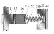
- 1 is a schematic diagram of a vane sliding structure showing a first embodiment of the present disclosure;
- 1 is a schematic diagram showing an installation state of a cylinder outer elastic body according to the first embodiment of the present disclosure;
- FIG. 1 is a cross-sectional view taken along a plane perpendicular to a rotation axis of a vane sliding structure using an O-ring as an elastic body according to a first embodiment of the present disclosure.
- 1 is a cross-sectional view taken along a plane perpendicular to the rotation axis of a vane sliding structure in an example in which a vane end elastic body is provided inside a spring winding, according to a first embodiment of the present disclosure.
- FIG. 1 is a cross-sectional view taken along a plane perpendicular to the rotation axis of a vane sliding structure in an example in which a cylinder outer elastic body is provided on a protrusion provided on a lid that closes an opening in a cylinder outer wall, according to a first embodiment of the present disclosure.
- FIG. FIG. 11 is a cross-sectional view of a vane sliding structure showing a second embodiment of the present disclosure.
- FIG. 11 is a cross-sectional view of a vane sliding structure showing embodiment 3 of the present disclosure.
- FIG. 11 is a cross-sectional view of a vane sliding structure showing embodiment 4 of the present disclosure.
- FIG. 13 is a cross-sectional view of a vane sliding structure showing embodiment 5 of the present disclosure.
- FIG. 13 is a cross-sectional view of a vane sliding structure showing embodiment 6 of the present disclosure.
- FIG. 13 is a cross-sectional view of a vane sliding structure showing embodiment 7 of the present disclosure.
- the rotary compressor disclosed herein is a rotary compressor having a cylinder forming a compression chamber inside, and a piston that rotates eccentrically inside the cylinder, and is equipped with a vane that is slidable from the piston side to the radially outside of the cylinder and divides the compression chamber, a vane groove that defines the sliding direction of the vane and has an opening inside the cylinder, a spring that presses the vane from the radially outside of the cylinder to the piston side, and an elastic body that is provided at least one of the radially outer end of the vane of the cylinder and an opposing position in the cylinder radially opposite the vane, and has a smaller longitudinal elastic modulus than both the vane and the cylinder.
- FIG. 1 shows a cross-sectional view of an example of a rotary compressor in this embodiment.
- This cross-sectional view is a cross-sectional view of the rotary compressor on a plane parallel to the rotation axis of the piston.
- the rotary compressor 1 has a prime mover section 10 and a compression mechanism section 20 having a part rotated by the prime mover section 10.
- the prime mover section 10 shows an example of an electric motor that converts electrical energy into rotational energy.
- the prime mover section 10 may be configured to be outside the rotary compressor 1 and rotate the rotating part of the compression mechanism section 20 from outside.
- the compression mechanism 20 is connected to the prime mover 10 so that rotational energy can be transmitted.
- the compression mechanism 20 includes a cylinder 23 that forms a compression chamber, a piston 22 that rotates eccentrically within the cylinder 23, a vane 26 that is slidable from the piston 22 side to the radially outer side (outer wall side) of the cylinder 23 at an opening that opens to the radially inner side (inner wall side) of the cylinder 23 and divides the compression chamber, and a spring 30 that is provided at the opening and presses the vane 26 from the outer wall side of the cylinder 23 to the piston side (inner wall side of the cylinder 23) (from the radially outer side to the inner side of the cylinder 23).
- the central axis of rotation of the eccentrically rotating piston is called the rotation axis.
- the compression mechanism 20 also includes an elastic body 31 provided on at least one of the ends of the vanes 26 on the outer wall side of the cylinder 23 and the opposing portion of the inner wall surface of the cylinder 23 that faces the vanes 26.
- the elastic body 31 has a smaller modulus of longitudinal elasticity than both the vanes 26 and the cylinder 23.
- Figure 1 shows a cross-sectional view of a rotary compressor 1 having two compression chambers 52 that compress the gas. However, it is sufficient to have at least one compression chamber.
- the rotary compressor 1 also has a sealed container 40 that covers the prime mover unit 10 and the compression mechanism unit 20.
- a discharge pipe 41 is arranged on the side of the sealed container 40 opposite the side where the compression mechanism unit 20 is arranged, toward the prime mover unit 10, to discharge the compressed gas into a pipe (not shown) outside the sealed container 40.
- the prime mover 10 includes a stator 11 and a rotor 12.
- the stator 11 is fixed to the inner circumferential surface of the sealed container 40.
- the rotor 12 is disposed on the inner circumferential surface of the stator 11 with a gap between it and the stator 11.
- the rotation axis of the rotor 12 is the same as the rotation axis of the piston 22.
- the rotation axis of the rotor 12 is the axis of the crankshaft of the compression mechanism 20 extending toward the prime mover 10. That is, the rotor 12 forms a hollow cylindrical shape, and the crankshaft 21 is fixed to the inner circumference of this hollow cylindrical shape.
- the crankshaft 21 is connected to the piston 22 so that the piston 22 rotates eccentrically. With the above structure, the crankshaft 21 rotates with the rotation of the rotor 12, and the piston 22 rotates eccentrically within the cylinder 23.
- the compression mechanism 20 has two compression chambers in the direction of the rotation axis.
- a cylinder 23 is provided for each compression chamber, and the cylinders 23 are separated in the direction of the rotation axis by a plate 27.
- the cylinders 23 are arranged in two rows in the longitudinal direction of the sealed container 40, i.e., in the direction of the rotation axis.
- the first cylinder 23a on the motor unit 10 side is provided with a first bearing 24a that rotatably holds the crankshaft 21 on the end surface on the motor unit 10 side.
- the second cylinder 23b is provided on the opposite side of the rotation axis direction from the first cylinder 23a (motor unit 10 side) via a plate 27.
- the second cylinder 23b is provided on the end surface on the opposite side from the plate 27 with a second bearing 24b that holds the crankshaft 21.
- the first bearing 24a and the second bearing 24b hold the crankshaft 21 as a pair.
- the first bearing 24a and the second bearing 24b have a hollow cylindrical through hole with a diameter larger than the shaft diameter of the crankshaft 21, and are arranged so that this through hole covers the crankshaft 21 and holds the crankshaft 21 rotatably. Furthermore, the first bearing 24a on the motor unit 10 side has a discharge port 29 for discharging the refrigerant compressed in the cylinder 23. The refrigerant discharged from the discharge port 29 passes through piping (not shown) and is output from the sealed container 40 through the discharge pipe 41.
- FIG. 2 is a cross-sectional view of the compression mechanism 20 of the rotary compressor according to embodiment 1, taken along a plane perpendicular to the axis of rotation.
- the cylinder 23, piston 22, vane 26, and vane 26 of the spring and parts that come into contact with or may come into contact with vane 26 are depicted as the main parts of the compression mechanism 20.
- the spring, vane 26, and elastic body 31 are depicted as having parts that protrude forward from the cut surface of the other parts.
- crankshaft 21 is depicted as having a crankshaft eccentric portion 21a that is eccentric from the axis of rotation, and a piston 22 is provided on the outer periphery of this crankshaft eccentric portion 21a.
- a cylinder 23 having a cylindrical through hole that follows the rotation trajectory of the outer periphery of the piston 22 when the crankshaft 21 rotates is provided on the outer periphery of the piston 22.
- the crankshaft eccentric part 21a and the piston 22 rotate eccentrically, and when the piston 22 rotates eccentrically inside the through hole, the space between the inside of the through hole of the cylinder 23 and the piston 22 changes.
- the cylindrical inner wall surface of the cylinder 23 is provided with a vane groove 32, which is a groove along which the vane 26 slides in the radial direction of the cylinder 23 (perpendicular to the axis of rotation).
- a vane groove 32 which is a groove along which the vane 26 slides in the radial direction of the cylinder 23 (perpendicular to the axis of rotation).
- At the radial outer end of the vane groove 32 there is an inner wall that is nearly parallel to the outer wall surface of the cylinder 23, i.e., the radial end of the cylinder 23.
- the radial depth of the vane groove 32 is such that the radial end of the vane 26 does not come into sufficient contact with the piston 22 even if the vane 26 moves in this radial direction while maintaining contact with the piston 22.
- the vane groove 32 has an inner wall surface (the inner wall surface on the radial outer side of the cylinder 23) on the radial outer side of the cylinder 23.
- This inner wall is also called the radial outer end of the vane groove 32, or the radial outer side of the cylinder 23. If the spring 30 were not present, the vane 26 would slide along the vane groove 32 and move radially outward, coming into contact with the radially outer end of the vane groove 32 or the radially outer side of the cylinder 23.
- the radially outer side of the cylinder 23 is the part where a cross section perpendicular to the movement direction of the vane 26 of the vane groove 32 provided in the cylinder 23 is projected onto the inner wall surface of the cylinder 23 in the direction of the same movement.
- the radially outer side of the cylinder 23 is the part that comes into contact with the inner wall surface of the cylinder 23 at the back of the vane groove 32 when the vane 26 slides within the vane groove 32 and moves radially outward of the cylinder 23. If there is an innermost end face of the vane groove 32 in the vane movement direction, this contact part can be said to be the radially outer end of the vane groove 32.
- a cylindrical hole (recess) or through hole may be provided in the radially outer portion of the vane groove 32 of the cylinder 23, facing radially outward of the cylinder 23.
- the cylinder 23 may be arranged inside the sealed container 40, and the through hole at the radially outer end of the groove of the cylinder 23 may be blocked by a lid portion, which is a means for blocking a hole, such as the inner wall of the sealed container 40 or a bolt.
- the cylindrical hole (recess) or through hole in the radially outer portion of the vane groove 32 of the cylinder 23 may be considered as a spring storage hole, which will be described later.
- a vane groove axial hole that penetrates in the direction of the rotation axis may be provided midway along the radial direction of the cylinder 23 of the groove.
- the space between the piston 22 and the inside of the through hole provided in the rotation axis direction of the cylinder 23 is separated into a suction chamber 51 and a compression chamber 52 by the vane 26. That is, the vane 26 is a partition plate that separates the space between the inner wall of the cylinder 23 and the piston 22 into the suction chamber 51 and the compression chamber 52.
- the vane 26 is arranged in a groove so that it can move in the radial direction of the cylinder 23, and the inner side of the cylinder in the radial direction contacts the piston 22.
- a spring 30 is provided on the end face of the vane 26 on the radial outer side of the cylinder 23 to bias the vane 26 against the inner wall surface of the cylinder 23 or the sealed container 40 so that the vane 26 is always in contact with the piston 22. That is, the vane 26 is pressed against the piston 22 located on the radial inner side by the spring force of the spring 30 provided on the radial outer side.
- one end of the spring 30 in the extension direction contacts the vane 26.
- the other end of the spring 30 in the extension direction may be arranged so that the end of the spring 30 on the radially outer side of the cylinder 23 enters a hole (recess) or through hole provided at the end of the vane groove 32 on the radially outer side of the cylinder 23.
- a spring storage hole 33 is provided that is larger than the thickness of the vane groove 32 and stores the spring 30 so that the spring 30 can expand and contract.
- this spring storage hole 33 is configured to communicate with a hole or through hole provided at the end of the vane groove 32 on the radially outer side of the cylinder 23, there is no risk of getting caught on a step or the like, and the spring 30 can expand and contract smoothly.
- the cross section of the spring storage hole 33 perpendicular to the extension direction of the spring 30 may be cylindrical in accordance with the shape of the spring 30, if the outer shape of the spring 30 is approximately cylindrical. Even if the spring storage hole 33 is provided in the vane groove 32, the vane groove 32 that regulates the movement of the vane 26 still exists, and the radially outer end of the vane groove 32 or the radially outer side of the cylinder 23 exists.
- the cylinder 23 is also provided with an intake port 28 for drawing in the refrigerant, which penetrates the cylinder 23 in the radial direction.
- the outer peripheral surface of the cylinder 23 in the radial direction may be fixed to the inner peripheral surface of the sealed container 40.
- vanes 26 may come into contact with each other, i.e., the vane groove 32 in the cylinder 23 and the structure that causes the vanes 26 to slide using the spring 30 (hereinafter also referred to as the "vane sliding structure").
- Figure 3 is a cross-sectional view of the vane sliding structure of embodiment 1, cut in the thickness direction of the cylinder 23 (cut along a plane parallel to the rotation axis and the radial direction).
- a piston 22 is disposed on the outer periphery of the eccentric portion 21a of the crankshaft 21, and a vane 26 is pressed against and held in place by the spring force of a spring 30 against the outer periphery of the piston 22.
- the vane 26 moves in the radial direction of the cylinder 23 in response to the rotation of the crankshaft 21 and the piston 22.
- the spring 30 is placed inside the spring storage hole 33 of the vane groove 32 in the radial direction of the cylinder 23.
- the spring 30 has a tapered shape in which the coil outer diameter becomes thinner as it approaches the radial inside of the cylinder 23.
- the end of the spring 30 on the side that does not contact the vane 26 may be fixed between the radial end of the spring storage hole 33 and the outer circumferential surface of the spring 30 coil by a crimping force caused by pressing, or it may not be fixed.
- liquid refrigerant may get mixed into the suction chamber 51 inside the cylinder 23 during operation.
- the piston 22 rotates with liquid refrigerant mixed into the suction chamber 51, the internal pressure rises suddenly.
- pressure is applied to the vane 26, which is a partition plate separating the suction chamber 51 and the compression chamber 52 inside the cylinder 23.
- the vane 26 is a partition plate separating the suction chamber 51 and the compression chamber 52 inside the cylinder 23.
- the wire of the spring 30 may penetrate into the radial inside (or outside) of the adjacent winding (spirals), causing excessive stress.
- the external shape of the spring 30 has a parallel portion parallel to the direction in which the spring 30 expands and contracts, and a tapered portion that forms an angle with the direction in which the spring 30 expands and contracts, the parallel portion may penetrate into the tapered portion, causing excessive stress.
- the spring 30 may be damaged by fatigue. If the spring 30 is not fixed to the vane 26, the vane 26 side of the spring 30 will continue to move when the vane 26 collides with the cylinder 23 (or the vane groove 32). For this reason, the spring 30 may be damaged by fatigue due to intense vibration (abnormal vibration, surging) in which the winding (spiral) of the spring 30 repeatedly comes into contact with and separates from the adjacent winding. Surging is a phenomenon that occurs when an external force with a frequency component close to the natural frequency of the spring is applied.
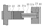
- Figure 3 is a cross-sectional view of the sliding structure of the vane 26 on a plane perpendicular to the rotation axis
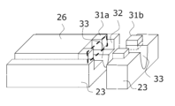
- Figure 4 is an oblique projection of the sliding structure of the vane 26
- Figure 5 is an oblique projection showing the mounting state of the cylinder side outer elastic body 31b to the cylinder 23.
- the compression mechanism 20 includes an elastic body 31 (31a, 32b) provided on at least one or both of the end of the vane 26 on the outer wall side of the cylinder 23 and the opposing portion facing the vane 26 on the inner wall surface of the cylinder 23.
- the elastic body 31 (31a, 32b) has a smaller modulus of longitudinal elasticity than both the vane 26 and the cylinder 23. This will be described in detail below.
- the vane 26 is provided with an elastic body 31 (31a) at its outermost end on the radial outside of the cylinder 23.
- the portion where the elastic body 31 is provided is the portion where the radially outer end of the vane 26 comes into contact with the radially outer end of the vane groove 32 (cylinder 23) of the cylinder 23 when the spring 30 is compressed (or assuming that the spring 30 is not present) and the vane 26 moves radially outward from the cylinder 23.
- an elastic body 31 (31b) may be provided at the radially outer end of the vane groove 32 of the cylinder 23, the portion that comes into contact with the radially outer wall surface of the cylinder 23 (vane groove 32) when the vane 26 moves radially outward.
- the portion that comes into contact with the radially outer wall surface of the cylinder 23 (vane groove 32) is the portion surrounded by a dotted line in Figure 5.
- This portion of the cylinder outer elastic body 31b comes into contact with the portion of the vane end elastic body 31a surrounded by the dotted line in Figure 4.
- the elastic body 31 may be attached to either or both of the radially outer end of the vane 26 and the radially outer end of the cylinder 23 in the vane groove 32.
- the Young's modulus of elasticity of the elastic body 31 (31a, 31b) is smaller than the Young's modulus of elasticity of the vane 26 and the cylinder 23.
- the elastic body 31 (31a, 31b) is preferably made of a rubber or gel material.
- the elastic body 31 may have a modulus of longitudinal elasticity that is approximately 1 ⁇ 10 ⁇ 5 to 1 ⁇ 10 ⁇ 2 that of the vane 26 and the cylinder 23.
- the elastic body 31 is shown to be disposed on both the vane 26 surface where the vane 26 comes into contact with the cylinder 23 when vane flying occurs on the side opposite to the surface in contact with the piston 22, and on the surface of the radially outer end of the cylinder 23 (the radially outer end of the vane groove 32) that comes into contact with the vane 26, but it is sufficient if the elastic body 31 is disposed on at least one of them.
- the elastic body 31 may be attached by fixing it with an adhesive.
- the elastic body 31 may be fixed by forming a recess in the radially outer end of the vane 26 or cylinder 23 (the radially outer end of the vane groove 32), and then elastically deforming the elastic body 31 itself and pressing it in.
- the shape of the elastic body 31 (31a, 31b) is shown as a rectangular parallelepiped, but this is not limited to this.
- the elastic body 31 (31a, 31b) is annular or a part thereof.
- the elastic body 31 (31a, 31b) may be a so-called O-ring rubber material cut to the same thickness as the vane 26, i.e., the plate thickness (thickness in the rotation axis direction), and attached to the end face of the vane 26 opposite the side that contacts the piston 22, i.e., the radially outer side of the cylinder 23.
- FIG. 6 shows an example in which the elastic body 31 is made of rubber O-ring.
- an O-ring with an annular outer shape equal to or smaller than the plate thickness of the vane 26 is attached as the elastic body 31a to the end face of the vane 26, which is radially outward of the cylinder 23.
- an O-ring serving as elastic body 31b is attached to the radially outer side of cylinder 23.
- the O-ring surrounds the spring storage hole on the radially outer side of cylinder 23 and is provided at a position where it comes into contact with the end face of vane 26 on the radially outer side of cylinder 23.
- the O-ring, which is elastic body 31b is not only on the radially outer side of vane groove 32 (the portion where vane 26 is projected radially outward), but is also present around this.
- a circular groove is provided around the cross section of the spring storage hole and the hole is pressed in, this has the effect of making assembly easier.
- the cross-sectional shape of the elastic body 31 (31a, 31b) may be circular as shown in FIG. 6.
- the elastic body 31 (31a, 31b) is provided on both the radially outer end face of the vane 26 and the radially outer side of the cylinder 23, but the elastic body 31 may be provided on either the radially outer end face of the vane 26 or the radially outer side of the cylinder 23, or on both.
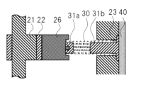
- the elastic body 31 (31a, 31b) is disposed outside the outer diameter of the spring 30, but it may be disposed inside the wire windings of the spring 30.
- the vane end elastic body 31a may have a hole that engages with an arrowhead-shaped protrusion provided on the radially outer end of the cylinder 23 of the vane 26, and may be shaped to enter inside the windings of the spring 30 when engaged with the arrowhead-shaped protrusion.
- the cylinder outer elastic body 31b is configured to be shaped to enter inside the winding of the wire at the radially outer end of the cylinder 23 of the spring 30 and to be fixed to the cylinder 23.
- the fixing method is to first provide a cylinder outer wall opening that opens to the radially outer side of the cylinder 23 at the spring storage hole 33. Next, the cylinder outer elastic body 31b can be pressed into the cylinder outer wall opening from the outer periphery side to the inner periphery side of the radially outer part of the cylinder 23 to be fixed.
- the outermost part of the radially outer part of the cylinder 23 at the spring storage hole 33 may be chamfered, and the cylinder radially outer end of the cylinder outer elastic body 31b may be bulged to engage with the chamfer. Furthermore, the bulged part of the cylinder radially outer end of the cylinder outer elastic body 31b is firmly fixed by engaging the sealed container 40 with the cylinder 23.
- the fixing method may be such that, instead of providing the vane end elastic body 31a, the cylinder outer elastic body 31b, which fits inside the wire windings of the spring 30, is inserted and fixed into the cylinder outer wall opening from the radially outside of the cylinder 23 in the spring storage hole 33.
- the cylinder outer elastic body 31b comes into direct contact with the vane 26 when vane flying occurs.
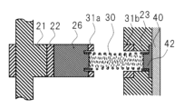
- a cylinder outer wall opening that opens radially outward of the cylinder 23 may be provided, a lid 42 that engages with the opening to close it may be attached, and the cylinder outer elastic body 31b may be fixed to a protrusion provided on the lid 42.
- the volume of the elastic body 31 (31a, 31b) itself can be made larger, which is expected to absorb more shock and reduce the impact speed.
- the radial dimension of the elastic body 31 in the cylinder 23 will be described.
- the position of the vane 26 in contact with the piston 22 when the gap between the outer periphery of the piston 22 and the inner periphery of the cylinder 23 is at a minimum in the position where the vane 26 (or vane groove 32) is arranged in the cylinder 23 is taken as the reference position.
- the dimension of the elastic body 31 (31a, 31b) in the moving direction of the vane 26 is the dimension of the vane 26 that does not come into contact with any parts in the moving direction of the vane 26, and does not come into contact with any parts with a design clearance.
- the elastic body 31 is provided partially in a part of the vane sliding structure, so it is believed that it is possible to prevent breakage of the spring 30 caused by the vane flying without increasing the size of the rotary compressor 1 or increasing the sliding resistance during normal operation.
- the mass that moves together with the vane 26 will be smaller, and the inertial force of what moves together with the vane 26 will be smaller.
- This will reduce the inertial force, which is one of the causes of the phenomenon known as vane jumping, making the phenomenon known as vane jumping less likely to occur.
- vane jumping does occur, the above-mentioned problems caused by it will not occur, or it is thought that the occurrence of the problems will be further suppressed.
- the elastic body 31, which has a smaller modulus of longitudinal elasticity than the vane 26 and the cylinder 23, is provided on both the radially outer end face of the cylinder 23 of the vane 26 and the radially outer end of the cylinder 23 (vane groove 32).
- this elastic body 31 (31a, 32b) is provided on both the radially outer end face of the vane 26 and the radially outer end of the vane groove 32, when the vane 26 and the cylinder 23 come into contact, the thickness of the elastic body 31 in the moving direction of the vane 26 becomes thicker than when the elastic body 31 is attached to only one side.
- the thickness (particularly the radial thickness) of the elastic body 31a, 32b can be made thicker, so the amount of impact energy absorption can be increased.
- the amount of mitigation of the collision speed acceleration (deceleration) on the deceleration side during a collision
- the above problems such as fatigue failure due to repeated impact loads at the fixed part of the spring 30 can be prevented.
- Embodiment 2 the radially outer end of the spring 30 of the cylinder 23 may or may not be fixed in the radially outer hole of the cylinder 23 by crimping force.
- the side of the spring 30 that contacts the vane 26 is fixed.
- the same reference numerals and terms are used in the same manner as in the above embodiment. Therefore, the structure of this embodiment also has the piston 22, the cylinder 23, the vane 26, the spring 30, the elastic body 31 (31a or 31b), the vane groove 32, and the spring storage hole 33.
- Figure 9 shows a cross-sectional view of the vane sliding structure of embodiment 2.
- the spring 30 has a portion at the end that comes into contact with the vane 26 where adjacent windings of the wire of the spring 30 are in contact with each other.
- the end of the spring 30 that comes into contact with the vane 26 has a portion where there is no pitch between the windings. This portion where there is no pitch between the windings of the end of the spring 30 that comes into contact with the vane 26 is fixed to the radially outer end of the cylinder 23 of the vane 26.
- the vane 26 and the portion of the spring 30 that has no pitch at the end that comes into contact with the vane 26 are fixed by crimping force by pressing the outer coil surface of the portion of the spring 30 that has no pitch between the protrusions at both ends of the width of the radially outer end of the cylinder 23 of the vane 26.
- An elastic body 31a may be provided radially outward of the protrusions at the radially outer end of the cylinder 23 of the vane 26.
- the radially outer end of the cylinder 23 of the spring 30 may be configured to be pressed against the radially outer end of the cylinder 23 of the spring storage hole 33 (when the inner wall of the cylinder 23 is located at the innermost part of the spring storage hole 33) or against the inner wall surface of the sealed container 40 radially outside the cylinder 23 of the spring storage hole 33 by the spring force of the spring 30 (not fixed radially).
- the radially outer end of the cylinder 23 of the spring 30 may be fixed to the radially outer end of the cylinder 23 of the spring storage hole 33.
- the spring 30 is fixed by a crimping force caused by pressing, but this is not limited to the above.
- the fixing method may also be by using brazing material, welding, a solvent, resin, or an adhesive.
- the elastic body 31 is provided on at least one or both of the end of the vane 26 on the outer wall side of the cylinder 23 (vane end elastic body 31a) and the opposing portion facing the vane 26 on the inner wall surface of the cylinder 23 (cylinder outer elastic body 31b).
- the collision speed between the vane 26 and the cylinder 23 can be mitigated, preventing repeated deformation of the wire of the spring 30 itself, such as overcoming adjacent spirals, or the wire penetrating inside the spiral, which would cause fatigue failure. This prevents breakage of the spring 30 due to the vane flying off, without requiring major structural changes to increase the size of the compressor or increase the sliding resistance during normal operation.
- the vane 26 and the spring 30 are fixed together, the vane 26 and the spring 30 do not separate, preventing wear caused by the wires coming into close contact with each other due to separation. Also, in the case where the radially outer end of the spring 30 on the cylinder 23 is not fixed to the radially outer end of the spring storage hole 33 on the cylinder 23, the process of fixing the spring 30 to the cylinder 23 during manufacturing can be eliminated.
- Embodiment 3 In the first embodiment, the radially outer end of the spring 30 of the cylinder 23 may or may not be fixed in the radially outer hole of the cylinder 23 by a crimping force.
- the side of the spring 30 that contacts the vane 26 In the second embodiment, an example in which the side of the spring 30 that contacts the vane 26 is fixed is described. In the present embodiment, an example in which the side of the spring 30 that contacts the vane 26 is fixed and the radially outer side of the spring 30 of the cylinder 23 is fixed to the cylinder 23 is shown. Note that, unless otherwise specified, when the same reference numerals and terms are used, they are the same as those in the above embodiment. Therefore, the structure of this embodiment also has the piston 22, the cylinder 23, the vane 26, the spring 30, the elastic body 31 (31a or 31b), the vane groove 32, and the spring storage hole 33.
- Figure 10 shows a cross-sectional view of the vane sliding structure of this embodiment.
- the spring 30 has a portion at the end that comes into contact with the vane 26 where adjacent windings of the wire of the spring 30 are in contact with each other.
- the end of the spring 30 that comes into contact with the vane 26 has a portion where there is no pitch between the windings.
- This portion of the spring 30 at the end that comes into contact with the vane 26 where there is no pitch between the windings is fixed to the radially outer end of the cylinder 23 of the vane 26. This is the same as in embodiment 2.
- the radially outer end of the spring 30 on the cylinder 23 is fixed to the radially outer end of the spring storage hole 33 on the cylinder 23.
- the end of the spring 30 on the side not in contact with the vane 26 has a portion where adjacent windings of the wire of the spring 30 are in contact with each other, i.e., a portion where there is no pitch between the windings.
- This portion where there is no pitch between the windings at the radially outer end of the spring 30 on the cylinder 23 is fixed by the crimping force caused by the press fit between the radial end of the spring storage hole 33 and the outer circumferential surface of the spring 30 coil.
- the outer diameter of the center of the spring 30 in the direction perpendicular to the direction of expansion and contraction may be smaller than both ends in the direction of expansion and contraction, forming a drum-shaped taper.
- the spring 30 has both ends, the end that contacts the vane 26 and the end on the radially outer side of the cylinder 23, which are fixed to the vane 26 and the spring storage hole 33 or the radially outer end of the cylinder 23, respectively.
- the spring 30 is fixed by a crimping force caused by pressing, but the fixing method is not limited to this.
- the fixing method may also be by using brazing material, welding, a solvent, resin, or an adhesive.
- the elastic body 31 is provided at least on one or both of the ends of the vane 26 on the radially outer side of the cylinder 23 (vane end elastic body 31a) and the opposing position in the cylinder 23 that faces the vane 26 in the cylinder radial direction (cylinder outer elastic body 31b).
- both ends of the spring 30 in the expansion and contraction direction are fixed, so even if a load is applied that separates the ends of the spring 30, they remain fixed, preventing wear caused by adhesion between the wires of the spring 30 due to separation.
- Embodiment 4 In the first embodiment, an example is shown in which the radially outer end of the cylinder 23 of the vane 26 is in direct contact with the spring 30. In this embodiment, an example is shown in which an elastic body 31 is provided between the radially outer end of the cylinder 23 of the vane 26 (the surface of the vane 26 opposite to the side contacting the piston 22) and the spring 30. Unless otherwise specified, the same reference numerals and terms are used to refer to the same as in the above embodiment. Therefore, the structure of this embodiment also includes the piston 22, the cylinder 23, the vane 26, the spring 30, the elastic body 31 (31a or 31b), the vane groove 32, and the spring storage hole 33.
- Figure 11 shows a cross-sectional view of the vane sliding structure of this embodiment.
- the vane 26 side of the winding closest to the vane 26 of the wire of the spring 30 is configured to contact an elastic body 31 (vane end elastic body 31a) provided at the radially outer end of the cylinder 23 of the vane 26.
- the vane end elastic body 31a is also provided on the surface that contacts the vane 26 side of the winding closest to the vane 26 of the wire of the spring 30 at the radially outer end of the cylinder 23 of the vane 26.
- the vane end elastic body 31a has protrusions that protrude radially outward from the cylinder 23 on both sides of the width direction on the radially outer side of the spring 30, and is shaped to surround the vane side end of the spring 30.
- the vane end elastic body 31a is integrally formed with a convex portion that protrudes radially outward of the cylinder 23 on both sides of the vane width direction end perpendicular to the movement direction and thickness direction of the vane 26, and a concave portion that contacts the spring 30 in the center of the vane width direction.
- the vane end elastic body 31a may be attached to the radially outer end of the cylinder 23 of the vane 26 by providing a protrusion on the radially outer end of the cylinder 23 of the vane 26 and assembling the vane end elastic body 31a with a hole that engages with this protrusion.
- the vane end elastic body 31a restricts the movement of the vane 26 in the width direction of the spring 30 whose end contacts the recessed portion by the convex portion at the width direction end of the vane 26.
- the recessed portion of the vane 26 of the vane end elastic body 31a receives the spring force from the spring 30 and pushes the vane 26 towards the piston 22.
- the recessed portion of the vane 26 of the vane end elastic body 31a receives the spring force from the spring 30 and elastically deforms at the contact portion with the spring 30, which also has the effect of restricting the movement of the vane 26 in the direction perpendicular to the moving direction.
- a cylinder outer elastic body 31b may be provided on the radially outer end side of the vane groove 32 (cylinder 23) of the cylinder 23 so as to come into contact with the widthwise protrusion of the vane end elastic body 31a.
- the vane end elastic body 31a may be combined with the form in which the elastic body 31 (31a, 31b) is provided inside the wire windings of the spring 30, as shown as an example in the first embodiment.
- the cylinder outer elastic body 31b in the first embodiment is shaped to fit inside the wire windings at the radially outer end of the cylinder 23 of the spring 30.
- This cylinder outer elastic body 31b can be combined with the vane end elastic body 31a, which is integrated with the convex portion at the vane width end and the concave portion at the vane width center.
- the dimensions to be set are the convex part at the vane width direction end of the vane end elastic body 31a, the concave part at the vane width direction center, and the dimensions of the cylinder outer elastic body 31b in the vane 26 movement direction.
- the dimensions of the vane 26 movement direction may be set so that one of these two contacts comes into contact first, and then the other comes into contact when the vane 26 moves further.
- the outer spacing and the inner spacing are made to match.
- the outer spacing is made smaller than the inner spacing.
- the impact speed of the vane 26 can be instantly suppressed. If the dimensions are set so that one of the two contacts occurs first and then the other contacts as the vane 26 continues to move forward, the impact speed of the vane 26 is suppressed in two stages, which is thought to result in a smaller impact on the equipment.
- the modulus of elasticity of the convex portion at the end of the vane width direction of the vane end elastic body 31a may be different from the overall modulus of elasticity of the concave portion at the center of the vane width direction of the vane end elastic body 31a and the cylinder outer elastic body 31b provided inside the wire windings of the spring 30. This is because, when the dimensions are set so that one of the two contacts comes into contact first and then the other comes into contact when the vane 26 advances further, the impact speed drops at the first contact, and then the second contact more strongly suppresses the impact speed, which is thought to reduce the impact.
- a widthwise central convex portion of the elastic body 31 that protrudes radially outward from the cylinder 23 may be provided at the widthwise central portion of the vane end elastic body 31a, inside the windings of the spring 30.
- the vane end elastic body 31a is integral with convex portions that protrude radially outward from the cylinder 23 at both ends in the vane width direction perpendicular to the movement direction and thickness direction of the vane 26, a concave portion that contacts the spring 30 at the vane width central portion, and the widthwise central convex portion provided in this concave portion.
- the vane end elastic body 31a with the widthwise central convex portion is used, when the vane jumps, the cylinder outer elastic body 31b provided inside the wire windings at the radially outer end of the cylinder 23 of the spring 30 comes into contact with the widthwise central convex portion of the vane end elastic body 31a.
- the effect of the elastic body 31 is improved by the volume of the widthwise central convex portion of the vane end elastic body 31a, and the collision speed between the vane 26 side and the radially outer end side of the cylinder 23 (acceleration (deceleration) on the deceleration side at the time of collision) is mitigated.
- the radially outer end of the cylinder 23 of the vane 26 is formed of a vane end elastic body 31a that contacts the spring 30, and the contacting vane end elastic body 31a is pressed toward the vane 26 by the spring force of the spring 30, making it difficult for the vane end elastic body 31a to come off the vane 26.
- the elastic body 31 (vane end elastic body 31a) to be attached can be made into a single component (elastic body), and the number of steps for assembling the elastic body can be reduced.
- Embodiment 5 In the above embodiment, there is no particular definition for the shape of the surface parallel to the vane movement direction which is the outer shape of the elastic body 31. In the present embodiment, an example will be described in which projections and recesses are provided on the surface parallel to the vane movement direction which is the outer shape of the elastic body 31.
- Figure 12 (1) is a cross-sectional view of the vane sliding structure of this embodiment.
- the elastic body 31 (vane end elastic body 31a, cylinder outer elastic body 31b) has concaves and convexes in a direction perpendicular to the moving direction of the vane 26, and the concaves are configured to mesh with the convex parts of the vane 26 or the convex parts of the cylinder 23.
- Figure 12 (2) shows a partially enlarged view of the convex parts of the vane 26.
- Figure 12 (3) shows an enlarged view of one side of the vane end elastic body 31a.
- the elastic body 31 has concave parts on both ends in the thickness direction of the vane 26, and meshes with the convex parts provided on both ends in the thickness direction of the radially outer protrusion of the vane 26.
- the cross-sectional area of the elastic body 31 in a section perpendicular to the sliding direction of the vane 26 changes from the piston 22 side toward the radially outer side of the cylinder 23.
- the shape of the radially outer protrusion of the vane 26 or the outer end of the cylinder 23 changes in response to the change in the cross-sectional area of the elastic body 31.
- the elastic body 31 has convex and concave portions in the direction perpendicular to the moving direction of the vane 26, even if a load is applied to the elastic body 31 (vane end elastic body 31a, cylinder outer elastic body 31b) that would cause it to come off the vane 26 or cylinder 23 when the vane 26 moves in the moving direction, the concave portions of the elastic body 31 engage with the convex portions of the vane 26 or the convex portions of the cylinder 23, preventing the elastic body 31 from coming off the vane 26 or the cylinder 23.
- the elastic body 31 (vane end elastic body 31a, cylinder outer elastic body 31b) flexibly deforms, allowing the concave portions of the elastic body 31 to engage with the convex portions of the vane 26 or the convex portions of the cylinder 23.
- Embodiment 6 In the first embodiment, an example was shown in which the end of the spring 30 on the radially outer side of the cylinder 23 is fixed to the spring storage hole 33 by a crimping force due to press-fitting. In the second embodiment, an example was shown in which the end of the spring 30 on the side contacting the vane 26 is fixed between the protrusions provided at both ends of the vane 26 in the width direction by a crimping force due to press-fitting.
- a protrusion is provided at the width direction center of the radially outer end of the cylinder 23 of the vane 26, or at a cover part that closes the cylinder outer wall opening of the spring storage hole 33 that opens to the radially outer side of the cylinder 23, and the inner circumference of the coil (winding) of the spring 30 is press-fitted to this protrusion and fixed.
- the same reference numerals and terms are used to refer to the same as in the above embodiment. Therefore, the structure of this embodiment also has the piston 22, the cylinder 23, the vane 26, the spring 30, the elastic body 31 (31a or 31b), the vane groove 32, and the spring storage hole 33.
- Figure 13 shows a cross-sectional view of the vane sliding structure of this embodiment.
- the spring 30 is fixed by pressing the inner circumferential surface of the coil (winding) rather than the outer circumferential surface of the coil (winding) at the end of the spring 30.
- the vane 26 has a protrusion that protrudes radially outward from the cylinder 23 at the widthwise center of the radially outer end of the cylinder 23.
- This protrusion is formed into a shape that is pressed into the inner circumferential surface of the coil (winding) at the vane 26 side end of the spring 30.
- the spring 30 is pressed into the protrusion provided at the widthwise center of the vane 26.
- a cylinder outer wall opening that opens radially outward of the cylinder is provided at the radially outer end of the cylinder 23 in the spring storage hole 33.
- a lid (press-fit plate) 42 that closes this cylinder outer wall opening is provided.
- This lid (press-fit plate) 42 has a protrusion that protrudes toward the piston 22.
- This protrusion is formed into a shape that is pressed into the inner circumferential surface of the coil (winding) at the radially outer end of the cylinder 23 of the spring 30. That is, the spring 30 is pressed into the protrusion provided on the lid (press-fit plate) 42 that closes the cylinder outer wall opening.
- the coil diameter of the tapered portion can be made the same as that of the parallel portion, and the stress generated in the spring 30 can be reduced.
- Embodiment 7 In the above embodiment, an example was shown in which the elastic body 31 is made of a rubber material or a gel material. In this embodiment, an example will be described in which the elastic body 31 is a spring. Unless otherwise specified, the same reference numerals and terms are used to refer to the same things as in the above embodiment. Therefore, the structure of this embodiment also has the piston 22, the cylinder 23, the vane 26, the spring 30, the elastic body 31 (31a or 31b), the vane groove 32, and the spring storage hole 33.
- Figure 14 shows a cross-sectional view of the vane sliding structure of this embodiment.
- a coiled elastic body 31a that expands and contracts in the same direction as the spring 30 is provided on the outer periphery of the winding of the spring 30 that connects to the radially outer end of the cylinder 23 of the vane 26.
- the coiled elastic body 31a is fixed by a crimping force caused by pressing into protrusions provided on both widthwise ends of the radially outer end of the cylinder 23 of the vane 26.
- a coil-shaped elastic body 31b which expands and contracts in the same direction as the spring 30, is provided around the spring storage hole 33 at the radially outer end of the cylinder 23 in the vane groove 32.
- the coil-shaped elastic body 31b is fixed by a crimping force caused by pressing into a circular groove provided at the radially outer end of the cylinder 23 in the vane groove 32 of the cylinder 23.
- the method of fixing is described as fixing by a crimping force caused by pressing, but this is not limited to this.
- the fixing method may also be fixing with a brazing material, welding, a solvent, a resin, or an adhesive.
- the coiled elastic body 31a and the coiled elastic body 31b may each be replaced with a leaf spring.
- a curved leaf spring elastic body 31a may be used in which one end of the leaf spring is pressed into a groove provided at both widthwise ends of the radially outer end of the cylinder 23 of the vane 26, and the other end is a free end. In this case, when the vane jumps, the curved portion of the curved leaf spring elastic body 31a is made to come into contact with the radially outer end of the cylinder 23 in the vane groove 32.
- a curved leaf spring elastic body 31b may be used in which one end of the leaf spring is pressed into a groove provided at the radially outer end of the cylinder 23 of the vane groove 32, and the other end is a free end. In this case, when the vane jumps, the curved part of the curved leaf spring elastic body 31b is made to come into contact with the radially outer end of the cylinder 23 of the vane 26.
- the coil-shaped elastic body 31a, the coil-shaped elastic body 31b and the leaf spring elastic body 31a, the leaf spring elastic body 31b may be located on either or both of the vane 26 side and the radially outer side of the cylinder 23.
- the coiled elastic body 31a, the coiled elastic body 31b and the leaf spring elastic body 31a, the leaf spring elastic body 31b are all made of spring steel, which provides high environmental resistance and durability, and allows the compressor to have a long life.
- Rotary compressor 10 Prime mover (electric motor) 11 stator 12 rotor 20 compression mechanism 21 crankshaft 21a crankshaft eccentric portion 22 piston 23, 23a, 23b cylinder 24, 24a, 24b bearing 26 vane 27 plate 28 intake port 29 discharge port 30 spring 31 elastic body 31a vane end elastic body 31b cylinder outer elastic body 32 vane groove 33 spring storage hole 40 sealed container 52 compression chamber.
Landscapes
- Engineering & Computer Science (AREA)
- Mechanical Engineering (AREA)
- General Engineering & Computer Science (AREA)
- Applications Or Details Of Rotary Compressors (AREA)
Abstract
Ce compresseur rotatif comprend : une aube (26) qui est disposée de façon à pouvoir coulisser d'un côté piston (22) vers le côté radialement externe d'un cylindre (23) et qui sépare une chambre de compression ; une rainure d'aube (32) qui définit la direction de coulissement de l'aube et comprend une ouverture à l'intérieur du cylindre ; un ressort (3) qui presse l'aube depuis le côté radialement externe du cylindre vers le côté piston ; et un corps élastique (31) qui est disposé au niveau d'une extrémité externe de l'aube dans une direction radiale du cylindre et/ou au niveau d'une position en regard, dans le cylindre, faisant face à l'aube dans la direction radiale du cylindre, et qui comporte un module d'élasticité longitudinale plus petit que l'aube ou le cylindre.
Priority Applications (2)
| Application Number | Priority Date | Filing Date | Title |
|---|---|---|---|
| PCT/JP2023/012776 WO2024201767A1 (fr) | 2023-03-29 | 2023-03-29 | Compresseur rotatif |
| JP2024539578A JP7619532B1 (ja) | 2023-03-29 | 2023-03-29 | ロータリー式圧縮機 |
Applications Claiming Priority (1)
| Application Number | Priority Date | Filing Date | Title |
|---|---|---|---|
| PCT/JP2023/012776 WO2024201767A1 (fr) | 2023-03-29 | 2023-03-29 | Compresseur rotatif |
Publications (1)
| Publication Number | Publication Date |
|---|---|
| WO2024201767A1 true WO2024201767A1 (fr) | 2024-10-03 |
Family
ID=92903630
Family Applications (1)
| Application Number | Title | Priority Date | Filing Date |
|---|---|---|---|
| PCT/JP2023/012776 Ceased WO2024201767A1 (fr) | 2023-03-29 | 2023-03-29 | Compresseur rotatif |
Country Status (2)
| Country | Link |
|---|---|
| JP (1) | JP7619532B1 (fr) |
| WO (1) | WO2024201767A1 (fr) |
Citations (6)
| Publication number | Priority date | Publication date | Assignee | Title |
|---|---|---|---|---|
| JPS51159010U (fr) * | 1975-06-12 | 1976-12-17 | ||
| JPH0226787U (fr) * | 1988-04-11 | 1990-02-21 | ||
| JPH07229487A (ja) * | 1994-02-17 | 1995-08-29 | Sanyo Electric Co Ltd | 回転式圧縮機 |
| JP2006329053A (ja) * | 2005-05-26 | 2006-12-07 | Fujitsu General Ltd | ロータリ圧縮機 |
| JP2007009861A (ja) * | 2005-07-04 | 2007-01-18 | Matsushita Electric Ind Co Ltd | 多気筒圧縮機 |
| JP2009228522A (ja) * | 2008-03-21 | 2009-10-08 | Daikin Ind Ltd | ロータリ圧縮機 |
Family Cites Families (1)
| Publication number | Priority date | Publication date | Assignee | Title |
|---|---|---|---|---|
| JP6109301B2 (ja) * | 2013-04-26 | 2017-04-05 | 三菱電機株式会社 | 多気筒回転圧縮機及びこの多気筒回転圧縮機を備えた蒸気圧縮式冷凍サイクル装置 |
-
2023
- 2023-03-29 WO PCT/JP2023/012776 patent/WO2024201767A1/fr not_active Ceased
- 2023-03-29 JP JP2024539578A patent/JP7619532B1/ja active Active
Patent Citations (6)
| Publication number | Priority date | Publication date | Assignee | Title |
|---|---|---|---|---|
| JPS51159010U (fr) * | 1975-06-12 | 1976-12-17 | ||
| JPH0226787U (fr) * | 1988-04-11 | 1990-02-21 | ||
| JPH07229487A (ja) * | 1994-02-17 | 1995-08-29 | Sanyo Electric Co Ltd | 回転式圧縮機 |
| JP2006329053A (ja) * | 2005-05-26 | 2006-12-07 | Fujitsu General Ltd | ロータリ圧縮機 |
| JP2007009861A (ja) * | 2005-07-04 | 2007-01-18 | Matsushita Electric Ind Co Ltd | 多気筒圧縮機 |
| JP2009228522A (ja) * | 2008-03-21 | 2009-10-08 | Daikin Ind Ltd | ロータリ圧縮機 |
Also Published As
| Publication number | Publication date |
|---|---|
| JP7619532B1 (ja) | 2025-01-22 |
| JPWO2024201767A1 (fr) | 2024-10-03 |
Similar Documents
| Publication | Publication Date | Title |
|---|---|---|
| US11739761B2 (en) | Fluid machine having a foil bearing arrangement | |
| EP2000671A1 (fr) | Compresseur | |
| JP4026318B2 (ja) | 密閉型電動圧縮機 | |
| JP2013108390A (ja) | 車両用圧縮機 | |
| US20130251576A1 (en) | Scroll compressor and processing method of scroll | |
| AU755604B2 (en) | Electromagnetic clutch and a compressor provided with electromagnetic clutch | |
| JP6479179B2 (ja) | モータ及び圧縮機 | |
| JP2013032767A (ja) | ベーン型圧縮機 | |
| US7938633B2 (en) | Electric compressor and electric motor with a housing having a circumferential wall with thick and thin portions | |
| US20160177953A1 (en) | Scroll compressor | |
| US11619217B2 (en) | Hermetic compressor | |
| JP7619532B1 (ja) | ロータリー式圧縮機 | |
| JP7182430B2 (ja) | 電動圧縮機 | |
| JP2000320460A (ja) | 圧縮機の軸受け構造 | |
| JP5730185B2 (ja) | スクロール型圧縮機 | |
| US20200088195A1 (en) | Scroll type compressor | |
| US10125770B2 (en) | Cylinder-rotation compressor with a discharge valve | |
| WO2004081378A2 (fr) | Structure de support de cylindre et compresseur volumetrique a pistons | |
| US6273692B1 (en) | Scroll-type compressor | |
| JP2024061304A (ja) | 電動圧縮機 | |
| JP2012036822A (ja) | 圧縮機 | |
| JP2016223600A (ja) | 気体圧縮機用の電磁クラッチ及び気体圧縮機 | |
| JPH07224770A (ja) | スクロール型圧縮機 | |
| KR102845968B1 (ko) | 스크롤 압축기 | |
| JP6570313B2 (ja) | 気体圧縮機用の電磁クラッチ及び気体圧縮機 |
Legal Events
| Date | Code | Title | Description |
|---|---|---|---|
| WWE | Wipo information: entry into national phase |
Ref document number: 2024539578 Country of ref document: JP |
|
| 121 | Ep: the epo has been informed by wipo that ep was designated in this application |
Ref document number: 23930407 Country of ref document: EP Kind code of ref document: A1 |
|
| NENP | Non-entry into the national phase |
Ref country code: DE |
|
| 122 | Ep: pct application non-entry in european phase |
Ref document number: 23930407 Country of ref document: EP Kind code of ref document: A1 |