WO2024201768A1 - 車体フロア構造 - Google Patents
車体フロア構造 Download PDFInfo
- Publication number
- WO2024201768A1 WO2024201768A1 PCT/JP2023/012778 JP2023012778W WO2024201768A1 WO 2024201768 A1 WO2024201768 A1 WO 2024201768A1 JP 2023012778 W JP2023012778 W JP 2023012778W WO 2024201768 A1 WO2024201768 A1 WO 2024201768A1
- Authority
- WO
- WIPO (PCT)
- Prior art keywords
- vehicle
- vehicle body
- reinforced resin
- band
- winding
- Prior art date
- Legal status (The legal status is an assumption and is not a legal conclusion. Google has not performed a legal analysis and makes no representation as to the accuracy of the status listed.)
- Ceased
Links
Images


Classifications
-
- B—PERFORMING OPERATIONS; TRANSPORTING
- B62—LAND VEHICLES FOR TRAVELLING OTHERWISE THAN ON RAILS
- B62D—MOTOR VEHICLES; TRAILERS
- B62D25/00—Superstructure or monocoque structure sub-units; Parts or details thereof not otherwise provided for
- B62D25/20—Floors or bottom sub-units
-
- B—PERFORMING OPERATIONS; TRANSPORTING
- B62—LAND VEHICLES FOR TRAVELLING OTHERWISE THAN ON RAILS
- B62D—MOTOR VEHICLES; TRAILERS
- B62D27/00—Connections between superstructure or understructure sub-units
- B62D27/06—Connections between superstructure or understructure sub-units readily releasable
- B62D27/065—Connections between superstructure or understructure sub-units readily releasable using screwthread
-
- B—PERFORMING OPERATIONS; TRANSPORTING
- B62—LAND VEHICLES FOR TRAVELLING OTHERWISE THAN ON RAILS
- B62D—MOTOR VEHICLES; TRAILERS
- B62D29/00—Superstructures, understructures, or sub-units thereof, characterised by the material thereof
- B62D29/04—Superstructures, understructures, or sub-units thereof, characterised by the material thereof predominantly of synthetic material
-
- B—PERFORMING OPERATIONS; TRANSPORTING
- B62—LAND VEHICLES FOR TRAVELLING OTHERWISE THAN ON RAILS
- B62D—MOTOR VEHICLES; TRAILERS
- B62D29/00—Superstructures, understructures, or sub-units thereof, characterised by the material thereof
- B62D29/04—Superstructures, understructures, or sub-units thereof, characterised by the material thereof predominantly of synthetic material
- B62D29/043—Superstructures
Definitions
- the technology disclosed herein relates to an automobile body floor structure that uses fiber-reinforced plastic composite materials.
- Patent Document 1 discloses a vehicle panel structure in which part of the floor of the vehicle body is constructed using reinforcing fibers. Specifically, the vehicle panel structure described in Patent Document 1 has a configuration in which a fiber-reinforced resin panel is fixed to a floor tunnel, cross member, and panel support part made of steel plate.
- the vehicle panel structure described in Patent Document 1 uses fiber-reinforced resin only in the floor panel portion, and there is still room for weight reduction. Meanwhile, the floor of the vehicle body is joined to multiple other structural materials such as the toe board and side sills, and requires strength or rigidity sufficient to withstand input loads in the event of any type of collision, such as a frontal collision, rearward collision, or side collision, or rollover. In particular, there is a need to design a load transfer path that distributes the input load and reduces deformation of the vehicle body.
- the technology disclosed herein has been developed in consideration of the above problems, and the purpose of this disclosure is to improve the load-bearing capacity and ensure a load transmission path when constructing a vehicle floor structure using fiber-reinforced plastic composite materials.
- a vehicle body floor structure made of a fiber-reinforced resin composite material, the vehicle body floor structure comprising a panel base material made of a fiber-reinforced resin composite material, and a continuous fiber-reinforced resin strip containing continuous fibers sewn onto the panel base material, the strip having a first connecting portion and a second connecting portion at both ends that are respectively joined to other structural materials in the panel base material.
- the technology disclosed herein can improve load-bearing capacity and ensure a load transfer path even when constructing a vehicle floor structure using fiber-reinforced plastic composite materials.
- FIG. 1 is a perspective view showing a schematic view of a portion of a vehicle body structure including a vehicle body floor structure according to an embodiment of the present invention
- FIG. 2 is an explanatory diagram showing a vehicle body floor structure according to the present embodiment
- 10 is an explanatory diagram showing an example of a method for fixing a winding portion to a panel base material in a vehicle body floor structure according to this embodiment.
- FIG. 3 is a cross-sectional view taken along the line II in FIG. 2.
- 4 is a cross-sectional view of a connection portion between a floor portion and a right center pillar of the vehicle body floor structure according to the present embodiment.
- Fig. 1 is a perspective view showing a schematic view of a part of a vehicle body structure including a vehicle body floor structure.
- the vehicle body structure shown in Fig. 1 is shown generally as viewed from the rear left to the front right of the vehicle body.
- the vehicle width direction may be expressed as the X direction, the vehicle front-rear direction (vehicle length direction) as the Y direction, and the vehicle height direction as the Z direction.
- the vehicle body structure shown in FIG. 1 includes a floor section 1, a front pillar 2, a center pillar 3, and a side sill 6.
- the lower end of the front pillar 2 is connected to the front end of the side sill 6, and the upper end is connected to the front end of a roof pillar (not shown).
- the lower end of the center pillar 3 is connected to the center in the vehicle length direction of the side sill 6, and the upper end is connected to the center in the vehicle length direction of the roof pillar (not shown).
- the roof pillar (not shown) extends along the vehicle length in the upper part of the vehicle interior space and forms the side portion of the vehicle roof.
- the side sill 6 extends along the vehicle length at the lower part of the side of the vehicle.
- the floor section 1 shown in FIG. 1 has a tunnel section 12 formed in the center in the vehicle width direction and extending along the vehicle length direction.
- the tunnel section 12 forms a space in which a propeller shaft is disposed to transmit torque output from an engine or drive motor mounted in the front of the vehicle body to the rear wheels, for example.
- the tunnel section 12 does not need to be provided in the floor section 1.
- the front pillar 2, center pillar 3, roof pillar, and side sill 6 may each be constructed as a component mainly made of fiber-reinforced resin.
- a component mainly made of fiber-reinforced resin refers to a composite material in which each component is composed of a panel of a fiber-reinforced resin composite material, and may also include components equipped with metallic reinforcing materials and fastening members.
- a fiber-reinforced resin composite is a component obtained by molding a fiber-reinforced resin that contains reinforcing fibers, mainly carbon fibers or aramid fibers, and a matrix resin, mainly thermoplastic resin or thermosetting resin.
- reinforcing fibers are not limited to carbon fibers and aramid fibers.
- multiple types of fibers may be used as reinforcing fibers.
- thermoplastic resins include polyethylene resin, polypropylene resin, polyvinyl chloride resin, ABS resin (acrylonitrile-butadiene-styrene copolymer synthetic resin), polystyrene resin, AS resin (acrylonitrile-styrene copolymer synthetic resin), polyamide resin, polyacetal resin, polycarbonate resin, polyester resin, PPS (polyphenylene sulfide) resin, fluororesin, polyetherimide resin, polyetherketone resin, polyimide resin, and the like.
- the matrix resin may be composed of one of these thermoplastic resins, or a mixture of two or more of them. Alternatively, the matrix resin may be a copolymer of these thermoplastic resins.
- thermoplastic resin When the thermoplastic resin is a mixture, a compatibilizer may be used in combination. Furthermore, a bromine-based flame retardant, a silicon-based flame retardant, red phosphorus, or the like may be added as a flame retardant to the thermoplastic resin.
- thermosetting resins examples include epoxy resins, unsaturated polyester resins, vinyl ester resins, phenolic resins, polyurethane resins, and silicone resins.
- the matrix resin may be composed of one of these thermosetting resins, or a mixture of two or more of them. When these thermosetting resins are used, appropriate curing agents and reaction accelerators may be added to the thermosetting resin.
- the reinforcing fibers may contain an appropriate ratio of fibers oriented in the axial direction and fibers oriented in a direction intersecting the axial direction. In addition to continuous fibers that extend continuously in a specific direction, the reinforcing fibers may also contain short fibers cut to a few millimeters.
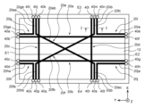
- FIG. 2 is a diagram for explaining the vehicle body floor structure of this embodiment.
- the floor portion 1 is configured to include a panel base material 10 and a plurality of continuous fiber reinforced resin strips 20.
- the plurality of continuous fiber reinforced resin strips 20 are components formed using a TFP (Talored Fiber Placement) method, and are configured to include continuous fibers sewn onto the panel base material 10.
- FIG. 1 shows the planar shape of the continuous fiber reinforced resin band 20 without taking into account the uneven shape caused by the tunnel section 12.
- the panel base material 10 is a part that determines the overall shape of the floor section 1. Like the front pillar 2 and center pillar 3 described above, the panel base material 10 is made of a fiber-reinforced resin composite material containing reinforcing fibers and matrix resin, and has a predetermined rigidity or strength. When the panel base material 10 contains continuous fibers, it is configured to contain, for example, continuous fibers oriented in the vehicle width direction and the vehicle body front-rear direction, and continuous fibers oriented in directions that form plus or minus 45 degrees with respect to the vehicle body front-rear direction and the vehicle width direction. This allows the panel base material 10 itself to have strength against impact loads acting in all directions.
- the thickness of the panel base material 10 is not particularly limited as long as it is a thickness that provides the desired rigidity, but can be, for example, within the range of 0.2 to 10.0 mm.
- the panel base material 10 has multiple winding sections 40 on the front, rear, left and right sides of the vehicle body.
- the winding sections 40 are members around which the continuous fibers that make up the multiple continuous fiber reinforced resin bands 20 are wound, and form both ends of each continuous fiber reinforced resin band 20.
- the panel base material 10 of the floor section 1 shown in Figure 2 has 20 winding sections 40.
- two winding portions a first winding portion 40a and a second winding portion 40b
- two winding portions a third winding portion 40c and a fourth winding portion 40d
- the positions at which the first winding portion 40a and the second winding portion 40b, and the third winding portion 40c and the fourth winding portion 40d are provided are aligned with the positions of the connection portions where the floor portion 1 is joined to a toe board (not shown).
- the fifth winding portion 40e and the sixth winding portion 40f are provided to the right of the tunnel portion 12 on the side E2 of the panel base material 10 on the vehicle rear side.
- the seventh winding portion 40g and the eighth winding portion 40h are provided to the left of the tunnel portion 12 on the side E2 of the panel base material 10 on the vehicle rear side.
- the positions at which the fifth winding portion 40e and the sixth winding portion 40f, and the seventh winding portion 40g and the eighth winding portion 40h are provided are aligned with the positions of the connection portions where the floor portion 1 and the rear panel (not shown) are joined.
- a ninth winding portion 40i, a tenth winding portion 40j, and an eleventh winding portion 40k are provided forward of the center of the side E3 of the panel substrate 10 on the right side of the vehicle body.
- the positions where the three winding portions are provided are aligned with the position of the connection portion where the floor portion 1 and the right front pillar 2 are joined.
- a twelfth winding portion 40l, a thirteenth winding portion 40m, and a fourteenth winding portion 40n are provided rearward of the center of the side E3 of the panel substrate 10 on the right side of the vehicle body.
- the positions where the three winding portions are provided are aligned with the position of the connection portion where the floor portion 1 and the right center pillar 3 are joined.
- a 15th winding portion 40o, a 16th winding portion 40p, and a 17th winding portion 40q are provided forward of the center of the side E4 on the left side of the vehicle body of the panel substrate 10.
- the positions where the three winding portions are provided are aligned with the position of the connection portion where the floor portion 1 and the left front pillar are joined.
- an 18th winding portion 40r, a 19th winding portion 40s, and a 20th winding portion 40t are provided rearward of the center of the side E4 on the left side of the vehicle body of the panel substrate 10.
- the positions where the three winding portions are provided are aligned with the position of the connection portion where the floor portion 1 and the left center pillar are joined.
- winding section 40 when it is not necessary to distinguish between the multiple winding sections, they will be collectively referred to as winding section 40. Also, when it is not necessary to distinguish between the multiple continuous fiber reinforced resin bands, they will be collectively referred to as continuous fiber reinforced resin bands 20.
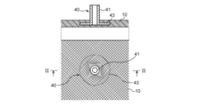
- FIG. 3 shows a plan view and a cross-sectional view taken along the line II-II of the panel substrate 10 to which the winding portion 40 is fixed.
- Each winding portion 40 can be fixed to the panel substrate 10 such that a part of the winding portion 40 is embedded in the continuous fibers contained in the panel substrate 10, as shown in FIG. 3, for example.
- the winding portion 40 shown in FIG. 3 has a main body 41 around which the continuous fibers are wound, and a base 43 having a larger diameter than the main body 41, and is fixed to the panel substrate 10 by pressing down the base 43 with the fibers (fibers oriented in a direction intersecting at 90 degrees in the figure) that make up the panel substrate 10. With this configuration, the winding portion 40 can be firmly attached to the panel substrate 10 without cutting the continuous fibers that make up the panel substrate 10.
- the method of attaching the winding portion 40 to the panel substrate 10 is not limited to the above example.
- the multiple continuous fiber reinforced resin bands 20 are each a component made of a band-shaped fiber reinforced resin containing continuous reinforced fibers sewn onto the panel base material 10.
- Each continuous fiber reinforced resin band 20 is disposed at two of the multiple winding sections 40 provided on the panel base material 10 as both ends.
- each continuous fiber reinforced resin band 20 includes continuous fibers wound around any two of the winding sections 40 provided on the panel base material 10 and arranged so as to go back and forth between the two winding sections 40 multiple times.
- the continuous fibers are arranged so as to go back and forth between the two winding sections 40 multiple times while being sewn to a predesigned position on the panel base material 10, and are hardened together with the matrix resin.
- the multiple continuous fiber reinforced resin bands 20 may include at least one longitudinal band portion arranged along the longitudinal direction of the vehicle body, at least one widthwise band portion arranged along the widthwise direction of the vehicle body, and at least one oblique band portion arranged partially or entirely in a direction intersecting the longitudinal direction of the vehicle body and the widthwise direction of the vehicle body.
- the continuous fiber reinforced resin bands 20 of the floor portion 1 shown in Figure 2 include a total of 10 continuous fiber reinforced resin bands 20.
- the multiple continuous fiber reinforced resin bands 20 include two longitudinal band portions 20a, 20b arranged along the longitudinal direction of the vehicle body, two widthwise band portions 20c, 20d arranged along the width direction of the vehicle, and two oblique band portions 20e, 20f arranged in a direction that intersects with the longitudinal direction of the vehicle body and the width direction of the vehicle.
- the multiple continuous fiber reinforced resin bands 20 include a first longitudinal band portion 20a arranged along the longitudinal direction of the vehicle body on the right side of the tunnel portion 12, and a second longitudinal band portion 20b arranged along the longitudinal direction of the vehicle body on the left side of the tunnel portion 12.
- the first longitudinal band portion 20a includes continuous fibers wound around the second winding portion 40b and the sixth winding portion 40f and sewn to the panel base material 10.
- the second longitudinal band portion 20b includes continuous fibers wound around the third winding portion 40c and the seventh winding portion 40g and sewn to the panel base material 10.
- the plurality of continuous fiber reinforced resin bands 20 also include a first widthwise band portion 20c arranged along the vehicle width direction forward of the center in the vehicle longitudinal direction, and a second widthwise band portion 20d arranged along the vehicle width direction rearward of the center in the vehicle longitudinal direction.
- the first widthwise band portion 20c includes continuous fibers wound around the 11th winding portion 40k and the 17th winding portion 40q and sewn to the panel base material 10.
- the second widthwise band portion 20d includes continuous fibers wound around the 12th winding portion 40l and the 18th winding portion 40r and sewn to the panel base material 10.
- the plurality of continuous fiber reinforced resin bands 20 include a first oblique band portion 20e arranged along the floor portion 1 from the right front to the left rear, and a second oblique band portion 20f arranged along the floor portion 1 from the left front to the right rear.
- the first oblique band portion 20e includes continuous fibers wound around the tenth winding portion 40j and the nineteenth winding portion 40s and sewn to the panel base material 10.
- the first oblique band portion 20e includes two first portions 20ea, 20ec arranged along the vehicle width direction from the tenth winding portion 40j provided in front of the vehicle right side edge and the nineteenth winding portion 40s provided behind the vehicle left side edge, and a second portion 20eb bent from each of the two first portions and arranged in a direction intersecting the vehicle body longitudinal direction and the vehicle width direction.
- the second oblique belt portion 20f includes continuous fibers wound around the 13th winding portion 40m and the 16th winding portion 40p and sewn to the panel base material 10.
- the second oblique belt portion 20f includes two first portions 20fa and 20fc arranged along the vehicle width direction from the 16th winding portion 40p provided in front of the left side of the vehicle and the 13th winding portion 40m provided behind the left side of the vehicle, and a second portion 20fb bent from each of the two first portions and arranged in a direction intersecting the vehicle body front-rear direction and the vehicle width direction.
- the multiple continuous fiber reinforced resin bands 20 shown in FIG. 2 each include four orthogonal bands including a first portion arranged along the vehicle longitudinal direction and a second portion bent from the first portion and arranged along the vehicle width direction.
- the first orthogonal band 20g includes continuous fibers wound around the first winding portion 40a and the ninth winding portion 40i and sewn to the panel base material 10.
- This first orthogonal band 20g has a first portion 20ga arranged along the vehicle longitudinal direction from the first winding portion 40a provided on the right side of the vehicle front side edge E1, and a second portion 20gb bent from the first portion and arranged in the vehicle width direction toward the ninth winding portion 40i provided in front of the vehicle right side edge E3.
- the second orthogonal band 20h includes continuous fibers wound around the fourth winding portion 40d and the fifteenth winding portion 40o and sewn to the panel base material 10.
- This second orthogonal band portion 20h has a first portion 20ha arranged along the vehicle longitudinal direction from the fourth winding portion 40d provided on the left side of the vehicle front side edge E1, and a second portion 20hb bent from the first portion and arranged along the vehicle width direction toward the 15th winding portion 40o provided in front of the vehicle left side edge E4.
- the third orthogonal belt portion 20i includes continuous fibers wound around the fifth winding portion 40e and the fourteenth winding portion 40n and sewn to the panel base material 10.
- the third orthogonal belt portion 20i has a first portion 20ia arranged along the vehicle longitudinal direction from the fifth winding portion 40e provided on the right side of the vehicle rear side edge E2, and a second portion 20ib bent from the first portion and arranged along the vehicle width direction toward the fourteenth winding portion 40n provided on the rear side of the vehicle right side edge E3.
- the fourth orthogonal belt portion 20j includes continuous fibers wound around the eighth winding portion 40h and the twentieth winding portion 40t and sewn to the panel base material 10.
- This fourth orthogonal band portion 20j has a first portion 20ja arranged along the vehicle longitudinal direction from the eighth winding portion 40h provided on the left side of the vehicle rear side edge E2, and a second portion 20jb bent from the first portion and arranged along the vehicle width direction toward the 20th winding portion 40t provided on the rear side of the vehicle left side edge E4.
- FIG. 4 shows an arrow view of the II cross section of FIG. 2.
- the three bands, the second width direction band 20d, the second inclined direction band 20f, and the third orthogonal band 20i are collectively covered with the coating layer 23.
- each continuous fiber reinforced resin band 20 is covered individually or collectively with the coating layer 23.
- the coating layer may be formed using a fiber reinforced resin or a resin that does not contain reinforced fibers. This prevents the continuous fibers of the continuous fiber reinforced resin band 20 from being exposed on the surface, and when a load is input to the floor portion 1, the continuous fiber reinforced resin band 20 is less likely to separate from the panel base material 10 and can prevent the continuous fibers from unraveling.
- multiple continuous fiber reinforced resin bands 20 are formed by arranging two of the connection parts (first connection part and second connection part) connected to the toe board, the left and right front pillars, the left and right center pillars, and the rear panel at both ends. Therefore, the load input to the vehicle body during a vehicle collision, rollover, etc. can be transmitted to other structural materials via the multiple continuous fiber reinforced resin bands 20, dispersing the collision load.
- these continuous fiber reinforced resin bands 20 include a first longitudinal band portion 20a and a second longitudinal band portion 20b arranged along the vehicle body longitudinal direction, a first widthwise band portion 20c and a second widthwise band portion 20d arranged along the vehicle width direction, and a first oblique band portion 20e and a second oblique band portion 20f arranged in a direction intersecting the vehicle body longitudinal direction and the vehicle width direction. Therefore, the strength against compressive stress and tensile stress occurring in the vehicle longitudinal direction and the vehicle width direction is increased, and the torsional rigidity of the floor portion 1 is also increased.
- the vehicle body floor structure of this embodiment has increased rigidity against collision loads in the vehicle fore-and-aft direction (0 degree direction) or offset direction that are input through the toe board during a frontal collision such as a full-overlap collision or an offset collision, and can distribute the load.
- the vehicle body floor structure has increased rigidity against collision loads and torsional loads in the 0 degree direction, vehicle width direction (90 degree direction), or 45 degree direction that are input through the left and right front pillars during a frontal collision or roof crash due to rollover, and can distribute the load.
- the vehicle floor structure also has increased rigidity against 90-degree collision loads input through the left and right center pillars during a side collision, and can disperse the load. Furthermore, the vehicle floor structure has increased rigidity against 0-degree or 45-degree collision loads and torsional loads input through the rear panel during a front or rear collision, and can disperse the load.
- the vehicle floor structure made of fiber-reinforced resin composite improves the load-bearing capacity of the floor section 1 and can efficiently distribute the load input during a collision, rollover, etc., reducing deformation of the vehicle body and mitigating damage.
- CFRP prepregs are laminated using, for example, a molding die, to form a semi-molten intermediate substrate corresponding to the panel substrate 10.
- winding sections 40 are attached to the positions of the connections with other structural materials that have been designed in advance.
- each winding section 40 is provided with its axial direction aligned with the thickness direction of the intermediate substrate.
- the main body 41 of the winding section 40 is inserted between the continuous fibers contained in the prepregs, and the base 43 of the winding section 40 is pressed by the continuous fibers, so that a part of the winding section 40 is embedded in the intermediate substrate (see FIG. 3).
- the method of forming the intermediate substrate is not particularly limited.
- the continuous fiber is wound alternately around any two of the winding sections 40 while sewing the continuous fiber to the intermediate substrate along the predesigned positions, and a strip of continuous fiber is arranged on the intermediate substrate.
- the process of arranging the strip of continuous fiber at the positions corresponding to each continuous fiber reinforced resin strip 20 is repeated.
- the strip of continuous fiber sewn to the intermediate substrate is impregnated with matrix resin, and multiple continuous fiber reinforced resin strips 20 are preformed (TFP method).
- resin or CFRP prepregs are laminated to form the covering layer 23 so as to cover one or more strip-shaped continuous fibers.
- the preformed continuous fiber reinforced resin strip and covering layer are then cured together with the intermediate substrate to produce a floor section 1 having multiple continuous fiber reinforced resin strips 20 in predetermined positions.
- the winding portion 40 around which the continuous fibers constituting the continuous fiber reinforced resin band 20 are wound may be used to connect the floor portion 1 to another structural material.
- the first winding portion 40a and the second winding portion 40b and the third winding portion 40c and the fourth winding portion 40d provided on the side E1 of the floor portion 1 on the vehicle front side may be used as part of a connecting structure that connects the floor portion 1 to the toe board.
- the fifth winding portion 40e and the sixth winding portion 40f and the seventh winding portion 40g and the eighth winding portion 40h provided on the side E2 of the floor portion 1 on the vehicle rear side may be used as part of a connecting structure that connects the floor portion 1 to the rear panel.
- the ninth winding portion 40i, the tenth winding portion 40j, and the eleventh winding portion 40k provided on the front side of the side E3 on the vehicle right side of the floor portion 1 may be used as part of a connecting structure that connects the floor portion 1 to the right front pillar.
- the twelfth winding portion 40l, the thirteenth winding portion 40m, and the fourteenth winding portion 40n provided on the rear side of the side E3 on the vehicle right side of the floor portion 1 may be used as part of a connecting structure that connects the floor portion 1 to the right center pillar.
- the fifteenth winding portion 40o, the sixteenth winding portion 40p, and the seventeenth winding portion 40q provided on the front side of the side E4 on the vehicle left side of the floor portion 1 may be used as part of a connecting structure that connects the floor portion 1 to the left front pillar.
- the 18th winding portion 40r, the 19th winding portion 40s, and the 20th winding portion 40t provided on the rear side of the vehicle left side E4 of the floor portion 1 may be used as part of a connecting structure that connects the floor portion 1 to the left center pillar.
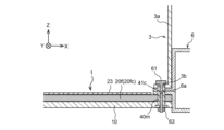
- FIG. 5 is a cross-sectional view of the connection portion between the floor portion 1 and the right center pillar 3, taken along the extension direction of the first portion 20fc of the second inclined band portion 20f.
- the 13th winding portion 40m penetrates the panel base material 10, and both axial ends are exposed on both sides of the floor portion 1.
- the 13th winding portion 40m has bolt holes 41c formed along the axis and opening at both axial ends of the 13th winding portion 40m.
- a connecting bolt 61 is inserted into the bolt hole 41c as a connecting member for connecting the floor portion 1 and the right center pillar 3.
- the 13th winding portion 40m around which the continuous fiber is wound is inserted into a hole 6a provided in the side sill 6 and a hole 3b provided in the right center pillar 3, and the floor portion 1 is fastened to the side sill 6 and the right center pillar 3 using the connecting bolt 61 and a nut 63.
- each winding section 40 is used to connect the floor section 1 to the toe board, rear panel, front pillar, and center pillar, respectively.
- each continuous fiber reinforced resin band 20 is firmly connected to the other structural materials, loads are efficiently transmitted from the other structural materials to the continuous fiber reinforced resin band 20 during a vehicle collision or rollover, and the loads can be efficiently distributed via the continuous fiber reinforced resin band 20.
- a continuous fiber reinforced resin band having two predetermined winding parts at both ends is exemplified, but the continuous fiber reinforced resin band in the technology disclosed herein is not limited to these examples.
- a continuous fiber reinforced resin band may be arranged with two winding parts at both ends other than the combination of two winding parts exemplified above.
- the planar pattern of each continuous fiber reinforced resin band is not limited to the example of the above embodiment, and may be designed arbitrarily according to the desired load transfer path.
- 1 floor portion
- 2 right front pillar
- 3 right center pillar
- 6 side sill
- 10 panel base material
- 12 tunnel portion
- 20 continuous fiber reinforced resin band
- 20a first longitudinal band portion
- 20b second longitudinal band portion
- 20c first widthwise band portion
- 20d second widthwise band portion
- 20e first oblique direction band portion
- 20f second oblique direction band portion
- 20g first orthogonal band portion
- 20h second orthogonal band portion
- 20i third orthogonal band portion
- 20j fourth orthogonal band portion
- 23 coating layer
- 40 winding portion
- 41 main body portion
- 43 base portion
- 61 connecting bolt
- 63 nut
Landscapes
- Engineering & Computer Science (AREA)
- Chemical & Material Sciences (AREA)
- Combustion & Propulsion (AREA)
- Transportation (AREA)
- Mechanical Engineering (AREA)
- Architecture (AREA)
- Structural Engineering (AREA)
- Body Structure For Vehicles (AREA)
Abstract
Description
まず、本実施形態に係る車体フロア構造を備えた車体構造の概略を説明する。
図1は、車体フロア構造を含む車体構造の一部を模式的に示す斜視図である。図1に示す車体構造は、車体の左後方から右前方を見た状態を概略的に示している。なお、図1に示すように、本明細書において、車幅方向をX方向、車体前後方向(車長方向)をY方向、車体高さ方向をZ方向と表記する場合がある。
続いて、本実施形態に係る車体フロア構造を詳細に説明する。
本実施形態の車体フロア構造では、フロア部1は、パネル基材10と、複数の連続繊維強化樹脂帯20を含んで構成される。複数の連続繊維強化樹脂帯20は、TFP(Talored Fiber Placement)工法を用いて形成される構成部分であり、パネル基材10上に縫い止めされた連続繊維を含んで構成される。
続いて、TFP工法を利用した車体フロア構造の一例を説明する。ただし、以下に説明する車体フロア構造の製造方法は一例にすぎず、本実施形態に係る車体フロア構造を製造する方法は、以下の例に限定されるものではない。
本実施形態において、連続繊維強化樹脂帯20を構成する連続繊維が巻回される巻回部40が、フロア部1と他の構造材との接続に用いられてもよい。具体的に、フロア部1の車両前側の辺E1に設けられた第1巻回部40a及び第2巻回部40bと第3巻回部40c及び第4巻回部40dは、フロア部1をトーボードに連結する連結構造の一部として用いられてもよい。同様に、フロア部1の車両後側の辺E2に設けられた第5巻回部40e及び第6巻回部40fと第7巻回部40g及び第8巻回部40hは、フロア部1をリアパネルに連結する連結構造の一部として用いられてもよい。
第13巻回部40mは、パネル基材10を貫通し、軸方向の両端部がフロア部1の両面に露出している。第13巻回部40mは、軸心に沿って形成されて第13巻回部40mの軸方向両端に開口したボルト孔41cを有する。ボルト孔41cには、フロア部1と右センターピラー3とを連結するための連結部材としての連結ボルト61が挿入される。連続繊維が巻回された第13巻回部40mは、サイドシル6に設けられた孔6a及び右センターピラー3に設けられた孔3bに挿入され、連結ボルト61及びナット63を用いてフロア部1とサイドシル6及び右センターピラー3が締結される。
Claims (5)
- 繊維強化樹脂複合材製の車体フロア構造であって、
繊維強化樹脂複合材からなるパネル基材と、
前記パネル基材における他の構造材とそれぞれ接合される第1の接続部及び第2の接続部を両端として配置され、前記パネル基材上に縫い止めされた連続繊維を含む連続繊維強化樹脂帯と、
を備える、車体フロア構造。 - 前記接続部に設けられ、前記連続繊維が巻回された巻回部を備え、
前記連続繊維は、
前記第1の接続部及び前記第2の接続部に設けられた前記巻回部にそれぞれ巻回されるとともに、前記第1の接続部及び前記第2の接続部の間を複数回往復して配置されている、
請求項1に記載の車体フロア構造。 - 前記連続繊維強化樹脂帯を複数備え、
複数の前記連続繊維強化樹脂帯は、
前記車体前後方向に沿って配設された少なくとも一つの前後方向帯状部と、
前記車幅方向に沿って配設された少なくとも一つの幅方向帯状部と、
一部又は全部が前記車体前後方向及び前記車幅方向に対してそれぞれ交差する方向に配設された少なくとも一つの傾斜方向帯状部と、
を含む、請求項1に記載の車体フロア構造。 - 前記傾斜方向帯状部は、
前記車体前後方向又は前記車幅方向に沿って配設された第1の部分と、
前記第1の部分から屈曲し前記車体前後方向及び前記車幅方向に対してそれぞれ交差する方向に配設された第2の部分と、
を含む、請求項3に記載の車体フロア構造。 - 前記巻回部は、前記車体フロア構造と前記他の構造材とを連結する連結構造に用いられる、請求項2に記載の車体フロア構造。
Priority Applications (3)
| Application Number | Priority Date | Filing Date | Title |
|---|---|---|---|
| JP2025509384A JPWO2024201768A1 (ja) | 2023-03-29 | 2023-03-29 | |
| PCT/JP2023/012778 WO2024201768A1 (ja) | 2023-03-29 | 2023-03-29 | 車体フロア構造 |
| US18/964,914 US20250091664A1 (en) | 2023-03-29 | 2024-12-02 | Vehicle body floor structure |
Applications Claiming Priority (1)
| Application Number | Priority Date | Filing Date | Title |
|---|---|---|---|
| PCT/JP2023/012778 WO2024201768A1 (ja) | 2023-03-29 | 2023-03-29 | 車体フロア構造 |
Related Child Applications (1)
| Application Number | Title | Priority Date | Filing Date |
|---|---|---|---|
| US18/964,914 Continuation US20250091664A1 (en) | 2023-03-29 | 2024-12-02 | Vehicle body floor structure |
Publications (1)
| Publication Number | Publication Date |
|---|---|
| WO2024201768A1 true WO2024201768A1 (ja) | 2024-10-03 |
Family
ID=92903590
Family Applications (1)
| Application Number | Title | Priority Date | Filing Date |
|---|---|---|---|
| PCT/JP2023/012778 Ceased WO2024201768A1 (ja) | 2023-03-29 | 2023-03-29 | 車体フロア構造 |
Country Status (3)
| Country | Link |
|---|---|
| US (1) | US20250091664A1 (ja) |
| JP (1) | JPWO2024201768A1 (ja) |
| WO (1) | WO2024201768A1 (ja) |
Citations (3)
| Publication number | Priority date | Publication date | Assignee | Title |
|---|---|---|---|---|
| JPH04135720A (ja) * | 1990-09-27 | 1992-05-11 | Mazda Motor Corp | 繊維強化樹脂成形品の製造方法 |
| JP2017061170A (ja) * | 2015-09-24 | 2017-03-30 | マツダ株式会社 | 車体補強構造 |
| JP2017165173A (ja) * | 2016-03-15 | 2017-09-21 | マツダ株式会社 | 車両用パネル構造 |
-
2023
- 2023-03-29 WO PCT/JP2023/012778 patent/WO2024201768A1/ja not_active Ceased
- 2023-03-29 JP JP2025509384A patent/JPWO2024201768A1/ja active Pending
-
2024
- 2024-12-02 US US18/964,914 patent/US20250091664A1/en active Pending
Patent Citations (3)
| Publication number | Priority date | Publication date | Assignee | Title |
|---|---|---|---|---|
| JPH04135720A (ja) * | 1990-09-27 | 1992-05-11 | Mazda Motor Corp | 繊維強化樹脂成形品の製造方法 |
| JP2017061170A (ja) * | 2015-09-24 | 2017-03-30 | マツダ株式会社 | 車体補強構造 |
| JP2017165173A (ja) * | 2016-03-15 | 2017-09-21 | マツダ株式会社 | 車両用パネル構造 |
Also Published As
| Publication number | Publication date |
|---|---|
| US20250091664A1 (en) | 2025-03-20 |
| JPWO2024201768A1 (ja) | 2024-10-03 |
Similar Documents
| Publication | Publication Date | Title |
|---|---|---|
| CN110282021B (zh) | 车辆框架结构 | |
| US8882183B2 (en) | Vehicle body structure | |
| CN108081926B (zh) | 车门加强梁 | |
| EP3538423B1 (en) | Chassis for a vehicle | |
| CN109249989B (zh) | 车辆用的转向支承构造体 | |
| JP5781031B2 (ja) | 自動車の車体前部構造 | |
| KR20230090717A (ko) | 차체 전방 구조 | |
| JP4462978B2 (ja) | 自動車のエネルギー吸収構造 | |
| US12384466B2 (en) | Vehicle body pillar structure and vehicle body structure | |
| JP2019156165A (ja) | 車体のセンターピラー | |
| JP7323402B2 (ja) | 繊維強化樹脂複合材及び繊維強化樹脂複合材の製造方法 | |
| WO2024201768A1 (ja) | 車体フロア構造 | |
| EP4416036A1 (en) | Chassis for a vehicle and method for forming a chassis for a vehicle | |
| JP7376293B2 (ja) | 繊維強化樹脂複合材及び繊維強化樹脂複合材の製造方法 | |
| US20210094244A1 (en) | Fiber-reinforced resin composite material and method of manufacturing fiber-reinforced resin composite material | |
| JP2023101861A (ja) | 車体構造部材 | |
| JP7035906B2 (ja) | ルーフリインフォースメント及び樹脂中空骨格部材の製造方法 | |
| JP7156757B2 (ja) | 車両用ピラー構造 | |
| US20250033704A1 (en) | Vehicle body pillar structure | |
| JP7824093B2 (ja) | 車体構造部材及び車体構造 | |
| JP7376295B2 (ja) | 繊維強化樹脂複合材及び繊維強化樹脂複合材の製造方法 | |
| JP5975820B2 (ja) | 車体構造 | |
| WO2025069199A1 (ja) | 車体側部構造 | |
| JP2017209897A (ja) | 繊維強化樹脂部品のフランジ製造方法及び繊維強化樹脂部品のフランジ構造 | |
| JP2025155118A (ja) | 車体構造部材の結合構造 |
Legal Events
| Date | Code | Title | Description |
|---|---|---|---|
| 121 | Ep: the epo has been informed by wipo that ep was designated in this application |
Ref document number: 23930408 Country of ref document: EP Kind code of ref document: A1 |
|
| ENP | Entry into the national phase |
Ref document number: 2025509384 Country of ref document: JP Kind code of ref document: A |
|
| WWE | Wipo information: entry into national phase |
Ref document number: 2025509384 Country of ref document: JP |
|
| NENP | Non-entry into the national phase |
Ref country code: DE |
|
| 122 | Ep: pct application non-entry in european phase |
Ref document number: 23930408 Country of ref document: EP Kind code of ref document: A1 |