WO2024201838A1 - Système de climatisation - Google Patents
Système de climatisation Download PDFInfo
- Publication number
- WO2024201838A1 WO2024201838A1 PCT/JP2023/012950 JP2023012950W WO2024201838A1 WO 2024201838 A1 WO2024201838 A1 WO 2024201838A1 JP 2023012950 W JP2023012950 W JP 2023012950W WO 2024201838 A1 WO2024201838 A1 WO 2024201838A1
- Authority
- WO
- WIPO (PCT)
- Prior art keywords
- outdoor
- sensor
- air
- ventilation
- control device
- Prior art date
- Legal status (The legal status is an assumption and is not a legal conclusion. Google has not performed a legal analysis and makes no representation as to the accuracy of the status listed.)
- Ceased
Links
Images









Classifications
-
- F—MECHANICAL ENGINEERING; LIGHTING; HEATING; WEAPONS; BLASTING
- F24—HEATING; RANGES; VENTILATING
- F24F—AIR-CONDITIONING; AIR-HUMIDIFICATION; VENTILATION; USE OF AIR CURRENTS FOR SCREENING
- F24F7/00—Ventilation
- F24F7/007—Ventilation with forced flow
-
- Y—GENERAL TAGGING OF NEW TECHNOLOGICAL DEVELOPMENTS; GENERAL TAGGING OF CROSS-SECTIONAL TECHNOLOGIES SPANNING OVER SEVERAL SECTIONS OF THE IPC; TECHNICAL SUBJECTS COVERED BY FORMER USPC CROSS-REFERENCE ART COLLECTIONS [XRACs] AND DIGESTS
- Y02—TECHNOLOGIES OR APPLICATIONS FOR MITIGATION OR ADAPTATION AGAINST CLIMATE CHANGE
- Y02B—CLIMATE CHANGE MITIGATION TECHNOLOGIES RELATED TO BUILDINGS, e.g. HOUSING, HOUSE APPLIANCES OR RELATED END-USER APPLICATIONS
- Y02B30/00—Energy efficient heating, ventilation or air conditioning [HVAC]
- Y02B30/70—Efficient control or regulation technologies, e.g. for control of refrigerant flow, motor or heating
Definitions
- This disclosure relates to air conditioning systems.
- the air in the room becomes polluted by the user's breathing and dust in the room, making it necessary to ventilate the room.
- the room is ventilated when there is a lot of fine particles such as pollen, yellow sand, or PM2.5 in the air, the air in the room will become polluted by these particles that have entered from outside.
- Patent document 1 JP Patent Publication No. 2022-66791 describes a ventilation system that detects the position of a human body in a room and directs the direction of the air blown out from the blowing section toward the position of the human body in the room.
- Patent Document 1 can purify indoor air, it cannot prevent dirty air from entering the room through ventilation. This can cause discomfort to users in the room.
- This disclosure has been made to solve the problems described above.
- the purpose of this disclosure is to provide an air conditioning system that can prevent dirty air from entering a room through ventilation, causing discomfort to users.
- the air conditioning system disclosed herein is an air conditioning system that includes an indoor unit that conditions the room, a ventilation device that ventilates the room, a control device, and a first outdoor sensor that detects the degree of outdoor air pollution, and the control device controls the ventilation operation of the ventilation device based on the degree of outdoor air pollution determined by the detection value of the first outdoor sensor.
- an air conditioning system that can prevent dirty air from entering a room through ventilation, thereby causing discomfort to users.
- FIG. 1 is a diagram showing a schematic configuration of an air conditioning system according to a first embodiment.
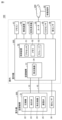
- FIG. 2 is a diagram showing the configuration of an outdoor unit. 1 is a block diagram showing the overall configuration of an air conditioning system.
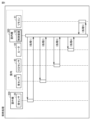
- FIG. 2 is a block diagram showing the functions of a control device.
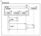
- FIG. 13 is a diagram showing a flow of continuous processing.
- FIG. 13 is a diagram showing the flow of ventilation stop processing.
- FIG. 11 is a diagram showing the flow of ventilation start processing.
- FIG. 13 is a diagram for explaining a threshold value related to outdoor particulate matter concentration.
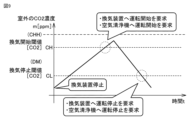
- FIG. 13 is a diagram for explaining a threshold value related to an indoor CO2 concentration.
- 4 is a flowchart showing a process executed by a control device.
- FIG. 4 is a flowchart showing a process executed by a control device.
- 10 is a flowchart showing a modified example of the process executed by the control device.
- FIG. 11 is a diagram showing a schematic configuration of an air conditioning system according to a second embodiment.
- FIG. 2 is a block diagram for explaining the processing content of a computing device for generating an estimation model.
- 1 is a flowchart showing a procedure for generating an estimation model.
- FIG. 11 is a diagram for explaining a first modified example regarding the outdoor unit.
- FIG. 11 is a diagram for explaining a second modified example regarding the outdoor unit.
- FIG. 11 is a diagram for explaining a third modified example regarding the outdoor unit.
- FIG. 13 is a diagram for explaining a fourth modified example regarding the outdoor unit.
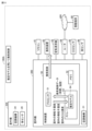
- Fig. 1 is a diagram showing a schematic configuration of an air conditioning system 100 according to the first embodiment.
- Fig. 2 is a diagram showing a configuration of an outdoor unit 200.
- Fig. 3 is a block diagram showing the overall configuration of the air conditioning system 100.
- the air conditioning system 100 comprises an outdoor unit 200, an indoor unit 300, a router 44, a remote control 41, a ventilation device 42, and an air purifier 43.
- the indoor unit 300, the router 44, the ventilation device 42, and the air purifier 43 are arranged indoors, which is an example of a space to be air-conditioned.
- the outdoor unit 200 is arranged outdoors.
- the air conditioning system 100 further includes dust sensors 26, 46 and a CO2 (carbon dioxide) sensor 45.
- the dust sensor 26 is provided in the outdoor unit 200.
- the CO2 sensor 45 and the dust sensor 46 are provided indoors.
- the outdoor unit 200 has an air conditioning mechanism 21.
- the indoor unit 300 has an air conditioning mechanism 31.
- the air conditioning mechanism 21 includes a compressor 22, a four-way valve 23, a heat exchanger 24, and an expansion valve 25.
- the air conditioning mechanism 31 includes a heat exchanger 34.
- the air conditioning mechanism 21 and the air conditioning mechanism 31 are connected by piping 10 through which a refrigerant flows.
- the outdoor unit 200 functions as a heat source unit.
- the indoor unit 300 exchanges heat with the heat source unit via the refrigerant to air condition the room.
- the outdoor unit 200 comprises a housing 201, a fan 27, and a service panel 202.
- the fan 27 is provided on the upper part of the housing 201.
- the heat exchanger 24 is disposed within the housing 201 so as to be aligned along one side of the housing 201. When the fan 27 rotates, air flows from the heat exchanger 24 toward the top of the outdoor unit 200.
- An opening for maintenance and inspection (not shown) is formed on the other side of the housing 201.
- the service panel 202 is detachably attached to the opening for maintenance and inspection.
- the dust sensor 26 is provided on one of the two sides of the service panel 202 that faces the inside of the housing 201 (the back side of the service panel 202). In this way, the dust sensor 26 is provided on a side different from the side on which the heat exchanger 24 is provided. Therefore, the sensing function of the dust sensor 26 is not affected by the airflow generated by the fan 27.
- the dust sensor 26 is also provided on the back side of the service panel 202. Therefore, the sensing function of the dust sensor 26 is not affected by direct sunlight, rainwater, etc.
- the indoor unit 300 is provided with a control device 50.
- the control device 50 controls the air conditioning mechanisms 21, 31 to condition the room at an appropriate air conditioning temperature.
- the dust sensors 26, 46, remote control 41, ventilation device 42, air purifier 43, router 44, and CO2 sensor 45 are connected wirelessly or by wire to the control device 50.
- the dust sensor 26 may be arranged in association with components provided in the outdoor unit 200, such as the heat exchanger 24, the fan in the outdoor unit 200, and a control box that controls the operation of the fan and compressor 22.
- Memory 52 provides a storage area for storing program codes or various variables when processor 51 executes various programs.
- Storage 53 provides a storage area for processor 51 to store information acquired from a sensor or the like.
- Memory 52 or storage 53 may be one or more non-transitory computer readable media.
- the dust sensor 26 detects the amount of fine particles contained in the air outside the room.
- the dust sensor 46 detects the amount of fine particles contained in the air inside the room. Fine particles include dust and dirt suspended in the air. Fine particles include, for example, pollen and PM2.5.
- the detection values of the dust sensors 26, 46 are transmitted to the control device 50.
- the dust sensors 26, 46 are examples of air quality sensors.
- the CO2 sensor 45 detects the CO2 concentration in the air in the room and transmits the detected value to the control device 50.
- the dust sensor 46 and the CO2 sensor 45 may be disposed in the indoor unit 300.
- the dust sensor 46 and the CO2 sensor 45 may be disposed in the air purifier 43.
- the ventilation device 42 performs ventilation operation to exchange the air inside the room with the air outside in response to a request from the control device 50.
- the ventilation device 42 may be configured with a ventilation fan, an automatic window opening and closing device, a total heat exchanger, etc.
- the air purifier 43 operates in response to a request from the control device 50 to remove pollen, dust, etc. from inside the room.
- the router 44 communicates with a mobile terminal 80 such as a smartphone via a cloud 400 configured on a network such as the Internet.
- the router 44 transmits various information to the user's mobile terminal 80 in response to a request from the control device 50.
- a communication system is constructed by the air conditioning system 100.
- control device 50 may be provided in the outdoor unit 200.
- the control device 50 may be provided in a location other than the outdoor unit 200 and the indoor unit 300.
- the storage 53 has a memory area 531 for storing various information.
- the acquisition unit 502 acquires detection values from the dust sensors 26, 46 and the CO2 sensor 45.
- the acquisition unit 502 acquires weather forecast information for the area in which the indoor unit 300 is located from the cloud 400.
- the communication unit 504 transmits a request command to an external device such as the ventilation device 42 and receives a response command from the external device.
- the external device returns a response command to the control device 50 in response to the request command.
- FIG. 6 is a diagram showing the flow of the ventilation stop process.
- the control device 50 executes the ventilation stop process when stopping the ventilation operation of the ventilation device 42.
- the processing unit 503 reads the outdoor particle concentration and weather forecast information from the memory area 531 (process 6).
- the processing unit 503 compares the outdoor particle concentration with the threshold value DH for stopping the ventilation operation.
- FIG. 7 is a diagram showing the flow of the ventilation start process.
- the control device 50 executes the ventilation start process when starting the ventilation operation of the ventilation device 42.
- the processing unit 503 reads the outdoor particulate concentration from the memory area 531 (process 9).
- the processing unit 503 compares the outdoor particulate concentration with the threshold DL for starting the ventilation operation.
- the processing unit 503 transmits a request command to the ventilation device 42 to request it to start operation (processing 10).
- the request command is transmitted to the ventilation device 42 via the communication unit 504.
- the ventilation device 42 starts ventilation operation and replies with a response command.
- FIG. 8 is a diagram for explaining thresholds related to outdoor particulate concentration.
- the control device 50 stores thresholds DH and DL related to outdoor particulate concentration. These thresholds are stored in the memory 52 of the control device 50.
- the threshold DM shown in FIG. 8 is used in a modified example. The modified example will be described later.
- the control device 50 when the outdoor particulate concentration exceeds the threshold value DH, the control device 50 requests the ventilation device 42 to stop ventilation operation and transmits warning information to the mobile terminal 80. After that, when the outdoor particulate concentration falls below the threshold value DL, the control device 50 requests the ventilation device 42 to start ventilation operation.
- FIG. 9 is a diagram for explaining thresholds related to the CO2 concentration in the room.
- the control device 50 stores thresholds CH and CL related to the CO2 concentration in the room. These thresholds are stored in the memory 52 of the control device 50. Note that the threshold CHH shown in FIG. 9 is used in a modified example. The modified example will be described later.
- control device 50 requests the ventilation device 42 to start ventilation operation when the indoor CO2 concentration exceeds the threshold CH.
- the control device 50 determines whether to start ventilation operation taking into account the outdoor particulate concentration. The process executed by the control device 50 will be described in detail below using a flowchart.
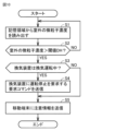
- FIGS. 10 and 11 are flowcharts showing the processing executed by the control device 50.
- the control device 50 reads the outdoor particulate concentration from the memory area 531 (step S1).
- the control device 50 determines whether the outdoor particulate concentration exceeds the threshold value DH (step S2). If the outdoor particulate concentration does not exceed the threshold value DH, the control device 50 returns the processing to step S1.
- the control device 50 reads the indoor CO2 concentration from the memory area 531 (step S11). Next, the control device 50 determines whether the indoor CO2 concentration exceeds the threshold CH (step S12).
- the control device 50 reads the outdoor particulate concentration from the memory area 531 (step S13). Next, the control device 50 determines whether the outdoor particulate concentration is below the threshold DL (step S14). If the outdoor particulate concentration is below the threshold DL, the control device 50 sends a request command to the ventilation device 42 to request it to start operation (step S15). This causes the ventilation device 42 to start ventilation operation, and less polluted outdoor air flows into the room. As a result, the indoor CO2 concentration can be reduced. Furthermore, because the air flowing in from outside is less polluted, it is possible to prevent the air flowing in from outside from polluting the indoor air.
- the control device 50 ends the processing based on this flowchart without requesting the ventilation device 42 to start operation. Therefore, even if the indoor CO2 concentration is higher than the threshold CH, if the outdoor particulate concentration is not below the threshold DL, a request command to start operation is not sent to the ventilation device 42. This makes it possible to prevent the indoor air from becoming polluted by outdoor particulates.
- step S12 determines whether the CO2 concentration in the room is less than the threshold value CL (step S16). If the CO2 concentration in the room is not less than the threshold value CL, the control device 50 returns the process to step S11. If the CO2 concentration in the room is less than the threshold value CL, the control device 50 sends a request command to the ventilation device 42 to request that the ventilation device 42 stop operating (step S17).
- Fig. 12 is a flowchart showing a modified example of the process executed by the control device.
- the flowchart shown in Fig. 12 has steps S111 to S114 added to the flowchart shown in Fig. 11.
- step S14 In the flowchart shown in FIG. 11, even if the indoor CO2 concentration is higher than threshold CH, if the outdoor particulate concentration is not below threshold DL (NO in step S14), ventilation operation is not started. In contrast, in the flowchart shown in FIG. 12, ventilation operation is started if the indoor CO2 concentration is extremely high, even if the outdoor particulate concentration is not below threshold DL. As a result, particulates such as PM2.5 flow into the room from outside. For this reason, the flowchart shown in FIG. 12 includes step S114, which starts the operation of air purifier 43.
- Steps S11 to S17 shown in FIG. 12 are the same as those shown in FIG. 11. For this reason, detailed descriptions of those steps will not be repeated here.
- control device 50 determines in step S14 shown in FIG. 12 that the outdoor particulate concentration is not less than the threshold DL, it determines whether the indoor CO2 concentration exceeds the threshold CHH (step S111).
- the threshold CHH is shown in FIG. 9. The threshold CHH is a value greater than the threshold CH. If the indoor CO2 concentration does not exceed the threshold CHH, the control device 50 ends the processing based on this flowchart.
- the control device 50 ends the processing based on this flowchart.
- step S14 the control device 50 determines that the outdoor particulate concentration is not below the threshold DL. Therefore, if the determination in step S112 is YES, the outdoor particulate concentration is equal to or greater than the threshold DL and less than the threshold DM. In this case, the control device 50 transmits a request command to the ventilation device 42 requesting it to start operation (step S113).
- the control device 50 causes the ventilation device 42 to start ventilation operation as long as the concentration is below the threshold DM, even if the particulate concentration outside is high. This makes it possible to lower the excessively high CO2 concentration in the room.
- the control device 50 sends a request command to the air purifier 43 to request it to start operation (step S114). This causes the air purifier 43 to start operating. As a result, particulates such as PM2.5 that flow into the room are removed. In this way, according to this modified example, it is possible to prevent the air in the room from becoming polluted by particulates flowing in from outside while lowering the excessively high CO2 concentration in the room.
- the first embodiment it is possible to provide an air conditioning system that can prevent dirty air from entering the room through ventilation, causing discomfort to the user.
- ventilation can be stopped before fine particles such as pollen and PM2.5 enter the room.
- the filter of the ventilation device 42 is less likely to become dirty by refraining from ventilation during periods or times when the outdoor air is polluted. This makes it possible to reduce the frequency of filter cleaning.
- appropriate ventilation operation can be performed automatically depending on the degree of pollution of the outdoor air and the CO2 concentration in the room.
- the control device 50 may use weather forecast information as a supplement to the detection value of the dust sensor 26 to determine the degree of pollution of the outdoor air. Furthermore, if the dust sensor 26 fails, the control device 50 may use weather forecast information to determine the degree of pollution of the outdoor air.
- the air conditioning system 100 may use weather forecast information as an auxiliary to perform preemptive ventilation operation even when the CO2 concentration is lower than the threshold CH.
- the air conditioning system 100 may use weather forecast information as an auxiliary to determine that the conditions for preemptively performing ventilation operation are met. Some examples of such conditions are listed below.
- the value detected by the dust sensor 26 is expected to increase.
- the air conditioning system 100 may determine the wind direction and wind speed using a wind vane and anemometer installed in the outdoor unit 200 instead of weather forecast information.
- the control device 50 determines the level of indoor air pollution based on the CO2 concentration in the room, and starts ventilation operation when the indoor air pollution exceeds the threshold CH (see FIG. 9). However, the control device 50 may also determine the level of indoor air pollution based on the detection value of the dust sensor 46 placed in the room.
- FIG. 13 is a diagram showing a schematic configuration of an air conditioning system 100A according to the second embodiment.
- the air conditioning system 100A according to the second embodiment differs from the air conditioning system 100 according to the first embodiment in that an estimation model 64 is stored in the storage 53.
- the air conditioning system 100A has a common configuration with the air conditioning system 100.
- Air conditioning system 100A performs ventilation operation when the CO2 concentration in the room becomes high.
- the CO2 concentration and particulate concentration in the room after ventilation operation can vary depending on the duration of ventilation operation, the airflow strength during ventilation operation, the CO2 concentration in the room before ventilation operation, and the particulate concentration in the room before ventilation operation.
- the air conditioning system 100A is configured to perform optimal ventilation operation using the estimation model 64.
- the control device 50 uses AI (artificial intelligence) to infer ventilation control data including ventilation operation time and airflow intensity based on state information (state variables) during ventilation operation.
- AI artificial intelligence
- the control device 50 executes ventilation operation based on the inferred ventilation control data.
- the control device 50 is equipped with an estimation model 64 for inferring ventilation control data.
- the estimation model 64 is an example of a trained model.
- the estimation model 64 is trained by machine learning to output ventilation control data for appropriately operating the ventilation device 42 for ventilation based on the input status information.
- the status information includes the outdoor particulate concentration, the indoor particulate concentration, and the indoor CO2 concentration.
- the control device 50 determines the outdoor particulate concentration based on the detection value of the dust sensor 26.
- the control device 50 determines the indoor particulate concentration based on the detection value of the dust sensor 46.
- the control device 50 determines the indoor CO2 concentration based on the detection value of the CO2 sensor 45.
- the processor 51 of the control device 50 inputs this state information into the estimation model 64.
- the estimation model 64 outputs ventilation control data.
- the control device 50 acquires the ventilation control data from the estimation model 64.
- the ventilation control data includes, for example, the time for which the ventilation operation continues and the airflow intensity of the ventilation operation.
- the processor 51 controls the ventilation operation pattern of the ventilation device 42 based on the ventilation control data.
- FIG. 14 is a block diagram for explaining the processing contents of the arithmetic device 60 for generating the estimation model 64.
- the arithmetic device 60 is, for example, a computer equipped with a processor and memory, similar to the control device 50.
- the control device 50 may be used as the arithmetic device 60.
- the arithmetic device 60 includes a learning unit 61.
- the learning unit 61 is realized by hardware and software, such as a processor and memory, that the arithmetic device 60 includes.
- the learning unit 61 stores an estimation model 64 for training by machine learning.
- Q-learning is one example of a reinforcement learning algorithm.
- the state s of the agent and the action a that the agent can select in state s are used as independent variables, and a function Q(s, a) that represents the value of an action when action a is selected in state s is learned.
- the optimal solution is to select action a that gives the highest value function Q in state s.
- “Action” is the determination of optimal ventilation control data based on state variables. Reward criteria are determined based on factors such as the indoor particulate concentration that changes before and after ventilation control. The reward criteria are determined by the indoor particulate concentration and CO2 concentration before and after ventilation operation.
- the reward will decrease.
- the greater the increase in indoor CO2 concentration the greater the decrease in reward.
- the indoor CO2 concentration is lower after ventilation operation than before, the reward will increase.
- the greater the decrease in indoor CO2 concentration the greater the increase in reward. Note that it is generally difficult to imagine that the outdoor CO2 concentration will increase after ventilation operation. For this reason, it is thought that in reality, the phenomenon of the amount of reward changing due to an increase in indoor CO2 concentration will not occur.
- the reward calculation unit 62 stores a point table for calculating the amount of reward.
- the point table includes points that correspond to the amount of change in particulate concentration before and after ventilation operation and the amount of change in CO2 concentration before and after ventilation operation. Points are an example of the amount of reward.
- the reward calculation unit 62 calculates the amount of reward using the point table.
- the function update unit 63 updates the function (action value function) for determining the reward control data based on the reward calculated by the reward calculation unit 62. This generates an estimation model 64.
- FIG. 15 is a flowchart showing the procedure for generating the estimation model 64.
- the calculation device 60 acquires training data required for generating the estimation model 64 (step S101).
- the training data is the "outdoor particulate concentration”, “indoor particulate concentration”, “indoor CO2 concentration”, and "ventilation control data” shown in FIG. 14.
- the calculation device 60 determines the relationship between the fine particle concentration in the room before and after the ventilation operation, and the relationship between the CO2 concentration in the room before and after the ventilation operation (step S102). Next, the calculation device 60 calculates the reward based on the reward criteria (step S103). Next, the calculation device 60 determines whether the calculation result matches the criteria for increasing the reward (step S104).
- the calculation device 60 If the calculation result meets the criteria for increasing the reward, the calculation device 60 increases the reward by an amount corresponding to the calculation result (step S105). If the calculation result does not meet the criteria for increasing the reward, the calculation device 60 decreases the reward by an amount corresponding to the calculation result (step S106). Next, the calculation device 60 updates the function for determining the ventilation control data (action value function) (step S107).
- the calculation device 60 determines whether or not the end condition is met (step S108). For example, the calculation device 60 determines that the end condition is met when a preset training period is completed.
- the ventilation passage 203 connects an inlet 204 provided in the service panel 202 with an outlet 205 provided on the top surface of the outdoor unit 200.
- the outlet 205 is provided in a location that is not affected by the airflow generated by the rotation of the fan 27.
- the sensing function of the dust sensor 26 is not affected by direct sunlight, rainwater, etc.
- the dust sensor 26 may be provided in a box separate from the outdoor unit 200.
- Fig. 18 is a diagram for explaining Modification 3 relating to the outdoor unit.
- a plurality of outdoor units 200A to 200C are provided in the air conditioning system 100.
- a dust sensor 26 is provided in each of the outdoor units 200A to 200C.
- Each dust sensor 26 transmits a sensor value (detection value) to the control device 50.
- the multiple dust sensors 26 output an abnormal value.
- Possible causes of an abnormal value being output include, for example, a sensor disconnection or a short circuit.
- the dust sensor 26 that outputs an abnormal value is likely to be malfunctioning.
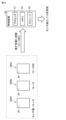
- the control device 50 determines the sensor value while excluding the abnormal value. As a result, in the example shown in FIG. 18, the control device 50 adopts "10" as the sensor value.
- Fig. 19 is a diagram for explaining Modification 4 relating to the outdoor unit.
- a plurality of outdoor units 200A-200C is provided in the air conditioning system 100.
- the dust sensor 26 provided in each of the plurality of outdoor units 200A-200C measures the particulate concentration and transmits the sensor value to the control device 50 at regular intervals.
- the dust sensor 26 for detecting outdoor air pollution is mounted on the outdoor unit 200. This can prevent the dust sensor 26 from breaking down due to exposure to rain and wind. Also, power can be supplied from the outdoor unit 200 to the dust sensor 26. Furthermore, it is easy to provide the sensor information acquired by the dust sensor 26 to the outdoor unit 200 or the indoor unit 300. Furthermore, it is also possible to easily transmit the sensor information to the cloud 400 by using a network constructed by the outdoor unit 200 and the indoor unit 300.
- the installation location of the dust sensor 26 is not limited to the outdoor unit 200. The dust sensor 26 may be installed at a location other than the outdoor unit 200 as long as it is a location where outdoor air pollution can be detected.
- the present disclosure relates to an air conditioning system.
- the air conditioning system (100, 100A) includes an indoor unit (300) that conditions the air inside a room, a ventilation device (42) that ventilates the room, a control device (50), and a first outdoor sensor (26) that detects the pollution of the outdoor air, and the control device controls starting and stopping of the ventilation operation of the ventilation device based on the degree of pollution of the outdoor air specified by the detection value of the first outdoor sensor (FIGS. 8 to 13).
- the air conditioning system described in paragraph 2 further includes a CO2 sensor (45) for detecting the CO2 concentration in the indoor air, and when the CO2 concentration determined by the detection value of the CO2 sensor exceeds a first indoor threshold value (CH) (step S12), the control device causes the ventilation device to start ventilation operation (steps S15 and S113) on the condition that the degree of pollution of the outdoor air is less than a second outdoor threshold value (DM) that is less than the first outdoor threshold value (DH) (less than DL (i.e., less than DM) in step S14, and less than DM in step S112).
- DM second outdoor threshold value
- DH first outdoor threshold value
- step S2 if the degree of air pollution determined by the detection value of the first outdoor sensor exceeds the first outdoor threshold (step S2), the control device transmits warning information to the user's mobile terminal (step S5).
- the air conditioning system described in paragraph 1 further includes an indoor sensor (46) for detecting indoor air pollution and a CO2 sensor (45) for detecting the CO2 concentration in the indoor air, and the control device generates control data for the ventilation operation (ventilation control data) based on the status data using a trained model (64) for inferring the duration of the ventilation operation, the status data including the degree of outdoor air pollution (outdoor particulate concentration) determined by the detection value of the first outdoor sensor, the degree of indoor air pollution (indoor particulate concentration) determined by the detection value of the indoor sensor, and the CO2 concentration (indoor CO2 concentration) determined by the detection value of the CO2 sensor, and the control device executes the ventilation operation based on the control data for the ventilation operation (FIG. 13).
- the trained model is trained by machine learning to output control data based on the state data (steps S101 to S108).
- the air conditioning system described in any one of paragraphs 1 to 7 further includes a first outdoor unit (200A), a second outdoor unit (200B), and a third outdoor unit (200C), the first outdoor sensor is provided in the first outdoor unit, the air conditioning system further includes a second outdoor sensor provided in the second outdoor unit, and a third outdoor sensor provided in the third outdoor unit (FIG. 17), and when the detection value of the first outdoor sensor and the detection value of the second outdoor sensor differ and the detection value of the second outdoor sensor and the detection value of the third outdoor sensor match, the control device identifies the degree of pollution of the outdoor air based on the detection value of the second outdoor sensor (FIG. 17).
- the air conditioning system described in any one of paragraphs 1 to 7 further includes a first outdoor unit (200A) and a second outdoor unit (200B), the first outdoor sensor is provided in the first outdoor unit, the air conditioning system further includes a second outdoor sensor provided in the second outdoor unit, and the control device, when there is an abnormality in the detection value of the first outdoor sensor, identifies the degree of pollution of the outdoor air based on the detection value of the second outdoor sensor (FIGS. 18 and 19).
- Air conditioning mechanism 21, 31 Air conditioning mechanism, 22 Compressor, 23 Four-way valve, 24, 34 Heat exchanger, 25 Expansion valve, 26, 46 Dust sensor, 27 Fan, 41 Remote control, 42 Ventilation device, 43 Air purifier, 44 Router, 45 CO2 sensor, 50 Control device, 51 Processor, 52 Memory, 53 Storage, 60 Arithmetic device, 61 Learning unit, 62 Reward calculation unit, 63 Function update unit, 64 Estimation model, 80 Mobile terminal, 100, 100A Air conditioning system, 200, 200A-200D Outdoor unit, 201 Housing, 202 Service panel, 203 Ventilation duct, 204 Entrance, 205 Exit, 300 Indoor unit, 400 Cloud, 501 Control unit, 502 Acquisition unit, 503 Processing unit, 504 Communication unit, 531 Storage area.
Landscapes
- Engineering & Computer Science (AREA)
- Chemical & Material Sciences (AREA)
- Combustion & Propulsion (AREA)
- Mechanical Engineering (AREA)
- General Engineering & Computer Science (AREA)
- Air Conditioning Control Device (AREA)
- Ventilation (AREA)
Abstract
L'invention concerne un système de climatisation (100) pourvu d'une unité intérieure (300) disposée dans une pièce dans laquelle un utilisateur est présent, d'un dispositif de ventilation (42), d'un dispositif de commande (50) et d'un premier capteur extérieur (26). Le dispositif de commande (50) commande le fonctionnement de ventilation du dispositif de ventilation (42) sur la base de la qualité de l'air extérieur, qui est spécifiée par une valeur détectée à partir du premier capteur extérieur (26). Par conséquent, le dispositif de commande (50) empêche la contamination par ventilation de l'air intérieur et évite de provoquer une gêne pour un utilisateur à l'intérieur de la pièce.
Priority Applications (1)
| Application Number | Priority Date | Filing Date | Title |
|---|---|---|---|
| PCT/JP2023/012950 WO2024201838A1 (fr) | 2023-03-29 | 2023-03-29 | Système de climatisation |
Applications Claiming Priority (1)
| Application Number | Priority Date | Filing Date | Title |
|---|---|---|---|
| PCT/JP2023/012950 WO2024201838A1 (fr) | 2023-03-29 | 2023-03-29 | Système de climatisation |
Publications (1)
| Publication Number | Publication Date |
|---|---|
| WO2024201838A1 true WO2024201838A1 (fr) | 2024-10-03 |
Family
ID=92903681
Family Applications (1)
| Application Number | Title | Priority Date | Filing Date |
|---|---|---|---|
| PCT/JP2023/012950 Ceased WO2024201838A1 (fr) | 2023-03-29 | 2023-03-29 | Système de climatisation |
Country Status (1)
| Country | Link |
|---|---|
| WO (1) | WO2024201838A1 (fr) |
Citations (8)
| Publication number | Priority date | Publication date | Assignee | Title |
|---|---|---|---|---|
| JPS51133121U (fr) * | 1975-04-18 | 1976-10-27 | ||
| JPH0482625U (fr) * | 1990-11-26 | 1992-07-17 | ||
| JPH109641A (ja) * | 1996-06-26 | 1998-01-16 | Daikin Ind Ltd | 空気調和機 |
| JP2002188844A (ja) * | 2000-12-19 | 2002-07-05 | Daikin Ind Ltd | 空気調和機 |
| JP2014240733A (ja) * | 2013-06-12 | 2014-12-25 | パナソニックIpマネジメント株式会社 | 環境判断システム、環境判断プログラム、及び、機器選択装置 |
| JP2016070600A (ja) * | 2014-09-30 | 2016-05-09 | パナソニックIpマネジメント株式会社 | 換気支援装置、プログラム |
| WO2018061147A1 (fr) * | 2016-09-29 | 2018-04-05 | 三菱電機株式会社 | Système de ventilation |
| JP2020016431A (ja) * | 2018-07-12 | 2020-01-30 | ダイキン工業株式会社 | 室内空気質の制御装置及び制御方法 |
-
2023
- 2023-03-29 WO PCT/JP2023/012950 patent/WO2024201838A1/fr not_active Ceased
Patent Citations (8)
| Publication number | Priority date | Publication date | Assignee | Title |
|---|---|---|---|---|
| JPS51133121U (fr) * | 1975-04-18 | 1976-10-27 | ||
| JPH0482625U (fr) * | 1990-11-26 | 1992-07-17 | ||
| JPH109641A (ja) * | 1996-06-26 | 1998-01-16 | Daikin Ind Ltd | 空気調和機 |
| JP2002188844A (ja) * | 2000-12-19 | 2002-07-05 | Daikin Ind Ltd | 空気調和機 |
| JP2014240733A (ja) * | 2013-06-12 | 2014-12-25 | パナソニックIpマネジメント株式会社 | 環境判断システム、環境判断プログラム、及び、機器選択装置 |
| JP2016070600A (ja) * | 2014-09-30 | 2016-05-09 | パナソニックIpマネジメント株式会社 | 換気支援装置、プログラム |
| WO2018061147A1 (fr) * | 2016-09-29 | 2018-04-05 | 三菱電機株式会社 | Système de ventilation |
| JP2020016431A (ja) * | 2018-07-12 | 2020-01-30 | ダイキン工業株式会社 | 室内空気質の制御装置及び制御方法 |
Similar Documents
| Publication | Publication Date | Title |
|---|---|---|
| KR102628483B1 (ko) | 밀폐형 구조물에서 공기 오염을 최소화하기 위한 라이브러리, 시스템 및 방법 | |
| JP6733734B2 (ja) | 換気システム | |
| US12044424B2 (en) | Variable air volume systems with filtration and air quality control | |
| JP7742550B2 (ja) | 空気質制御システム、空気質制御方法、及び、プログラム | |
| US12276432B2 (en) | System for minimizing indoor infection risk and maximizing energy savings | |
| EP3237808B1 (fr) | Agencement et procédé pour la gestion d'air d'une pièce | |
| JP6120820B2 (ja) | 換気システム | |
| JP7394641B2 (ja) | 空気調和換気システム | |
| JP6944962B2 (ja) | 汚れ情報推定システム | |
| KR102362793B1 (ko) | 바이오 공조 시스템 및 방법 | |
| CN107883532A (zh) | 新风机与空调联动系统及其控制方法、装置及存储介质 | |
| KR102611440B1 (ko) | 인공지능 공기정화 시스템 | |
| CN117128624A (zh) | 新风空调及空调管理系统的控制方法、装置和存储介质 | |
| JPH1078254A (ja) | 換気空調システム | |
| JP2020085375A (ja) | 換気装置 | |
| CN116147159A (zh) | 一种自动排风换气式办公空间空气循环系统 | |
| WO2021098530A1 (fr) | Système de climatisation intelligent | |
| WO2020192597A1 (fr) | Procédé et appareil de commande de nettoyage automatique pour climatiseur | |
| CN120488411A (zh) | 一种用于建筑工程的智能通风净化方法及系统 | |
| KR102628717B1 (ko) | 실내 공기 종합관리시스템 및 실내 공기 종합관리방법 | |
| JP2014163551A (ja) | 熱交換換気装置 | |
| CN117029124A (zh) | 生化空调系统以及方法 | |
| CN116608537B (zh) | 空调的控制方法、装置、电子设备和存储介质 | |
| CN117190462A (zh) | 一种多模块杀菌控制方法及空调系统 | |
| JP2025184582A (ja) | 空調システム |
Legal Events
| Date | Code | Title | Description |
|---|---|---|---|
| 121 | Ep: the epo has been informed by wipo that ep was designated in this application |
Ref document number: 23930476 Country of ref document: EP Kind code of ref document: A1 |
|
| NENP | Non-entry into the national phase |
Ref country code: DE |
|
| 122 | Ep: pct application non-entry in european phase |
Ref document number: 23930476 Country of ref document: EP Kind code of ref document: A1 |