WO2024201871A1 - Structure de véhicule - Google Patents
Structure de véhicule Download PDFInfo
- Publication number
- WO2024201871A1 WO2024201871A1 PCT/JP2023/013094 JP2023013094W WO2024201871A1 WO 2024201871 A1 WO2024201871 A1 WO 2024201871A1 JP 2023013094 W JP2023013094 W JP 2023013094W WO 2024201871 A1 WO2024201871 A1 WO 2024201871A1
- Authority
- WO
- WIPO (PCT)
- Prior art keywords
- vehicle
- base
- control unit
- electronic control
- width direction
- Prior art date
- Legal status (The legal status is an assumption and is not a legal conclusion. Google has not performed a legal analysis and makes no representation as to the accuracy of the status listed.)
- Ceased
Links
Images









Classifications
-
- B—PERFORMING OPERATIONS; TRANSPORTING
- B62—LAND VEHICLES FOR TRAVELLING OTHERWISE THAN ON RAILS
- B62D—MOTOR VEHICLES; TRAILERS
- B62D25/00—Superstructure or monocoque structure sub-units; Parts or details thereof not otherwise provided for
- B62D25/08—Front or rear portions
-
- B—PERFORMING OPERATIONS; TRANSPORTING
- B62—LAND VEHICLES FOR TRAVELLING OTHERWISE THAN ON RAILS
- B62D—MOTOR VEHICLES; TRAILERS
- B62D25/00—Superstructure or monocoque structure sub-units; Parts or details thereof not otherwise provided for
- B62D25/20—Floors or bottom sub-units
Definitions
- the present invention relates to a vehicle structure.
- Patent Document 1 shows a mounting structure in which, in the event of a vehicle collision, the base plate portion of the mounting bracket to which the ECU is attached receives an upward force from the assist piece portion, and this upward force causes the mounting piece portion to move upward while bending in an approximately L-shape starting from a triangular fold bead.
- the ECU fixed to the base plate portion moves upward, avoiding interference between the ECU and the reversing transmission.
- the present invention aims to provide a vehicle structure that can effectively protect the electronic control unit while keeping costs down.
- the present invention comprises the following configurations.
- a first in-vehicle device an electronic control unit disposed rearward in a vehicle front-rear direction with respect to the first vehicle-mounted device and at least a portion of the electronic control unit disposed in a position shifted in a vehicle width direction; a base that is attached to a vehicle body with the first on-board device and the electronic control unit placed thereon; Equipped with Vehicle structure.
- the present invention provides a vehicle structure that effectively protects the electronic control unit while keeping costs down.
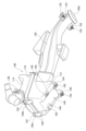
- FIG. 1 is a schematic plan view of the front part of a vehicle to which a vehicle structure according to an embodiment of the present invention is applied.
- FIG. 2 is a schematic plan view showing the positional relationship of on-vehicle components.
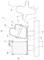
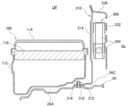
- FIG. 3 is a cross-sectional view taken along line III-III in FIG.
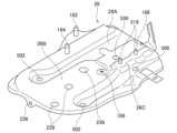
- FIG. 4 is a perspective view of the base.
- FIG. 5 is a perspective view of the air cleaner mounted on the base as viewed from the front side of the vehicle.
- FIG. 6 is a perspective view of the air cleaner mounted on the base as viewed from the rear side of the vehicle.
- FIG. 7 is a perspective view of the air cleaner.
- FIG. 8 is a perspective view of the air cleaner as viewed from below.
- FIG. 9 is a side view of the air cleaner.
- FIG. 1 is a schematic plan view of the front part of a vehicle to which a vehicle structure according to an embodiment of the present invention is applied.
- FIG. 2 is a schematic plan view showing the positional
- FIG. 10 is a perspective view of the battery mounted on the base as viewed from the front side of the vehicle.
- FIG. 11 is a perspective view of the battery mounted on the base as viewed from the rear side of the vehicle.
- FIG. 12 is a perspective view of the tray as seen from below.
- FIG. 13 is a perspective view of the electronic control unit mounted on the base.
- FIG. 14 is a perspective view of the electronic control unit mounted on the base as viewed from the outside in the vehicle width direction.
- FIG. 15 is a perspective view of the electronic control unit mounted on the mounting bracket.
- FIG. 16 is an exploded perspective view illustrating the mounting structure of the electronic control unit to the mounting bracket.
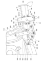
- FIG. 17 is a cross-sectional view taken along line XVII-XVII in FIG. FIG.
- FIG. 18 is a perspective view illustrating the mounting structure of the mounting bracket to the strut receiving portion.
- FIG. 19 is a perspective view of the base attached to the side frame.
- FIG. 20 is an exploded perspective view showing the mounting structure of the base to the side frame.
- FIG. 21 is a perspective view of a first fixing member and a second fixing member that support the base.
- FIG. 22 is a perspective view of a first fixing member and a second fixing member that support the base.
- FIG. 23 is a perspective view of the first fixing member as viewed from one side in the vehicle width direction.
- FIG. 24 is a perspective view of the first fixing member as viewed from the other side in the vehicle width direction.
- FIG. 25 is a perspective view of the second fixing member as viewed from one side in the vehicle width direction.
- FIG. 26 is a perspective view of the second fixing member as viewed from the other side in the vehicle width direction.
- Fig. 1 is a schematic plan view of the front of a vehicle 10 to which a vehicle structure according to an embodiment of the present invention is applied.
- Fig. 2 is a schematic plan view showing the positional relationship of on-vehicle parts.
- Fig. 3 is a cross-sectional view taken along line III-III in Fig. 2.
- the vehicle structure according to this embodiment is applied to the internal structure of an engine room 12 provided at the front of a vehicle 10.
- an air cleaner (second on-board device) 100, a battery (first on-board device) 200, and an electronic control unit (ECU: Electronic Control Unit) 300 are arranged on one side in the vehicle width direction.
- the battery 200 is disposed forward of the air cleaner 100 in the vehicle's fore-and-aft direction.
- the electronic control unit 300 is disposed rearward of the battery 200 in the vehicle's fore-and-aft direction, and is further disposed at a position offset in the vehicle width direction from the battery 200. As a result, the electronic control unit 300 is disposed to the side of the air cleaner 100 in the vehicle width direction.
- the air cleaner 100, the battery 200, and the electronic control unit (ECU) 300 are disposed on top of a single base 26.
- the air cleaner 100, the battery 200, and the electronic control unit (ECU) 300 are mounted on a single base 26 and supported from below by this base 26.
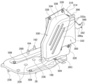
- FIG. 4 is a perspective view of the base 26.
- the base 26 has an air cleaner mounting portion 26A, a battery mounting portion 26B, and an ECU mounting portion 26C.
- the air cleaner 100 is mounted in the air cleaner mounting portion 26A
- the battery 200 is mounted in the battery mounting portion 26B
- the electronic control unit 300 is mounted in the ECU mounting portion 26C.
- the base 26 is attached to a side frame 14 that constitutes the chassis frame (vehicle body) of the vehicle 10 (see Figure 3).
- the chassis frame has a pair of side frames 14 that extend in the fore-and-aft direction of the vehicle and are spaced apart in the vehicle width direction, and these side frames 14 are connected to each other at multiple points spaced apart in the vehicle fore-and-aft direction by multiple cross members (not shown) that extend in the vehicle width direction.
- the base 26 is attached to one of the pair of side frames 14 (the left side) in the vehicle width direction in the engine compartment 12 at the front of the vehicle.
- the base 26 is attached to one of the side frames 14 by a first fixing member 30 and a second fixing member 32.
- the first fixing member 30 is disposed directly below the air cleaner 100 mounted on the air cleaner mounting portion 26A of the base 26, and the second fixing member 32 is disposed directly below the battery 200 mounted on the battery mounting portion 26B of the base 26.
- a master cylinder 16 is provided on the wall surface 12a on the passenger compartment side that constitutes the engine room 12. This master cylinder 16 is disposed rearward of the air cleaner 100 in the vehicle longitudinal direction. In other words, the air cleaner 100 and the battery 200 mounted on a base 26 are disposed in this order forward of the master cylinder 16 in the vehicle longitudinal direction. This master cylinder 16 is disposed rearward of the lower part of the air cleaner 100 in the vehicle longitudinal direction.
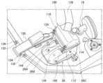
- FIG. 5 is a perspective view of the air cleaner 100 mounted on the base 26 as viewed from the vehicle front side.
- Fig. 6 is a perspective view of the air cleaner 100 mounted on the base 26 as viewed from the vehicle rear side.
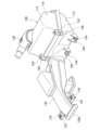
- Fig. 7 is a perspective view of the air cleaner 100.
- Fig. 8 is a perspective view of the air cleaner 100 as viewed from below.
- Fig. 9 is a side view of the air cleaner 100.
- the air cleaner 100 is attached to the air cleaner mounting portion 26A of the base 26.
- the air cleaner 100 has a resin case 110.
- This case 110 is box-shaped and made up of a lower case 112 and an upper case 114.
- the case 110 has a filter 116 in its internal space, which divides the internal space of the case 110 into upper and lower sections (see Figure 3).
- the lower case 112 is provided with locking pieces 120 having locking holes 120a at two locations on its rear surface.
- the upper case 114 is provided with locking protrusions 122 at two locations on its rear surface.
- the upper case 114 is attached to cover the upper part of the lower case 112 by inserting the locking protrusions 122 into the locking holes 120a of the locking pieces 120 of the lower case 112 and placing it over the lower case 112.
- the lower case 112 and the upper case 114 also have locking portions 124 at two locations on their front surfaces.
- One end of a clip 126 is connected to the locking portion 124 on the lower case 112 side.
- the clip 126 is formed from an elastic metal plate, and the other free end can be locked to the upper case 114 side. In other words, by rotating this clip 126 and engaging the free end with the upper case 114, the upper case 114 is maintained in an assembled state with the lower case 112.
- the air cleaner 100 is equipped with an intake duct 130.
- the intake duct 130 is connected to the front side of the lower case 112.
- the intake duct 130 is connected to the lower case 112 at a position closer to the inside in the vehicle width direction, that is, at a position closer to the engine side opposite the outside in the vehicle width direction.
- the intake duct 130 extends forward in the vehicle front-rear direction.
- the intake duct 130 has a connection part 132 at its tip, and this connection part 132 is fastened and fixed to the vehicle body by a bolt 134.
- the air cleaner 100 also includes a connecting duct (duct) 136.
- the connecting duct 136 is connected to an inner corner in the vehicle width direction on the rear surface of the upper case 114. This connecting duct 136 extends in the vehicle width direction and is connected to the engine (not shown).
- air is drawn in through the intake port 130a at the end of the intake duct 130.
- the air drawn into the intake duct 130 passes through a filter 116 provided in the internal space of the case 110, and is then sent to the engine via the connecting duct 136. Note that even if water is drawn into the intake duct 130 along with the air, this water collects at the bottom of the lower case 112 of the air cleaner 100 and is not sent to the engine.
- the underside of the air cleaner 100 is the mounting portion 140, which is attached to the air cleaner mounting portion 26A of the base 26.
- the mounting portion 140 has engagement portions 142, 144, an abutment portion 146, and a fastening portion 148.
- the engagement portions 142, 144 are disposed on the inside of the vehicle width direction, which is the engine side of the air cleaner 100, and the abutment portion 146 and the fastening portion 148 are disposed on the outside of the vehicle width direction, which is the opposite side of the air cleaner 100 from the engine side.
- the engagement parts 142, 144 are provided with bushings 150 made of, for example, rubber or plastic.
- a buffer plate 152 made of, for example, a rubber sheet is attached to the abutment part 146.
- a bolt 154 is provided to the fastening part 148.
- Pins 162, 164 are erected on the air cleaner mounting portion 26A of the base 26 at positions corresponding to the engagement portions 142, 144, a smooth abutment surface 166 is provided at a position corresponding to the abutment portion 146, and a bolt hole 168 is provided at a position corresponding to the fastening portion 148 (see Figure 4).
- the air cleaner 100 is placed from above on the air cleaner mounting portion 26A of the base 26.
- the pins 162, 164 are inserted into and engaged with the bushings 150 of the engagement portions 142, 144, and the buffer plate 152 of the abutment portion 146 abuts against the abutment surface 166.
- the bolts 154 of the fastening portions 148 are screwed into the bolt holes 168 of the base 26 and fastened, whereby the air cleaner 100 is attached to the air cleaner mounting portion 26A of the base 26.
- the air cleaner 100 is engaged with the base 26 by the pins 162, 164 and the bush 150 on the inside in the vehicle width direction, which is the engine side. Furthermore, on the outside in the vehicle width direction, which is the opposite side to the engine side, the abutment portion 146 of the air cleaner 100 is abutted against the abutment surface 166 of the base 26 on the rear side in the vehicle longitudinal direction, and the fastening portion 148 is fastened to the base 26 by the bolt 154 on the front side in the vehicle longitudinal direction, and is firmly fixed.
- the air cleaner 100 is attached to the base 26 at its mounting portion 140 so that the engine side in the vehicle width direction can displace in response to external forces from the engine. Therefore, the mounting portion 140 of the air cleaner 100 on the base 26 can absorb external forces associated with engine roll and the like that are transmitted to the air cleaner 100 through the connecting duct 136.
- the case 110 is inclined toward the rear in the vehicle's fore-and-aft direction toward the top of the vehicle, and the filter 116 is disposed inside the case 110 with the rear side in the vehicle's fore-and-aft direction inclined downward (see FIG. 3). Therefore, the direction of the air flow sucked in from the front side in the vehicle's fore-and-aft direction through the intake duct 130 is gently changed and passed through the filter 116. This reduces the loss of air pressure in the air cleaner 100.
- a large space S1 can be secured between the air cleaner 100 and the master cylinder 16 arranged at the rear of the lower part of the air cleaner 100 in the vehicle longitudinal direction. This makes it possible to more effectively prevent contact between the air cleaner 100 and the master cylinder 16 arranged at the rear side of the air cleaner 100 in the vehicle longitudinal direction.
- a large space S2 can be secured above the air cleaner 100 and the battery 200.
- the fastening portion 148 of the air cleaner 100 is positioned so that it overlaps with the space S2 between the air cleaner 100 and the battery 200 when viewed from the top-bottom direction of the vehicle, so that the fastening portion 148 of the air cleaner 100 can be easily fastened to the base 26 by passing a tool through the space S2 and using the bolt 154.
- the case 110 of the air cleaner 100 is inclined rearward in the vehicle front-rear direction toward the top of the vehicle, when an external force caused by engine roll is transmitted to the air cleaner 100 through the connecting duct 136, the external force can be applied evenly to the upper part of the case 110. This makes it possible to prevent the opening at the joint between the lower case 112 and the upper case 114.
- Fig. 10 is a perspective view of the battery 200 mounted on the base 26 as viewed from the front side of the vehicle.
- Fig. 11 is a perspective view of the battery 200 mounted on the base 26 as viewed from the rear side of the vehicle.
- Fig. 12 is a perspective view of the tray 220 as viewed from below.
- the battery 200 is attached to the battery mounting portion 26B of the base 26.
- the battery 200 has a rectangular parallelepiped shape and has negative and positive terminals 212 on its top surface 210.
- the battery 200 When attached to the battery mounting section 26B of the base 26, the battery 200 is arranged with its front surface 214 and rear surface 216 facing forward and backward in the vehicle longitudinal direction, and both side surfaces 218 facing in the vehicle width direction.
- the battery 200 is attached to the battery mounting section 26B of the base 26 while placed on a tray 220.
- the tray 220 has a rectangular bottom surface 222 and a peripheral wall 224 standing upward from the outer edge of the bottom surface 222.
- the bottom of the battery 200 is fitted into the tray 220 from above.
- the tray 220 has two positioning protrusions 226 on its bottom surface, which fit into positioning holes 228 formed in the battery mounting portion 26B of the base 26 (see FIG. 4). As a result, the battery 200 mounted on the tray 220 is positioned in the battery mounting portion 26B of the base 26.
- the battery 200 is fixed to the base 26 by a stay 230 and a rod 232.
- the stay 230 is provided with a pressure plate portion 230a having holes (not shown) at both ends.
- the rod 232 is a rod body with a male thread formed on one end, and a hook 234 formed by bending the rod body is provided at the other end of the rod 232.
- a locking hole 236 is formed in the battery mounting portion 26B of the base 26, and the hook 234 of the rod 232 can be locked into the locking hole 236.
- the battery 200 is placed on the tray 220, which is positioned and placed on the battery mounting section 26B of the base 26. With the battery 200 placed on the battery mounting section 26B, the hooks 234 of the rods 232 are engaged with the engagement holes 236 of the base 26. One end of each of these rods 232 is then passed through the hole in the pressure plate section 230a of the stay 230, and the nut 238 is screwed onto one end of the rod 232 to fasten them together. As a result, the battery 200 is attached to the battery mounting section 26B of the base 26 while being pressed against the base 26 by the stay 230 and the rod 232.
- FIG. 13 is a perspective view of the electronic control unit 300 mounted on the pedestal 26.
- Fig. 14 is a perspective view of the electronic control unit 300 mounted on the pedestal 26, as viewed from the outside in the vehicle width direction.
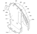
- Fig. 15 is a perspective view of the electronic control unit 300 mounted on the mounting bracket 310.
- Fig. 16 is an exploded perspective view illustrating the mounting structure of the electronic control unit 300 to the mounting bracket 310.
- Fig. 17 is a cross-sectional view taken along line XVII-XVII in Fig. 2.
- Fig. 18 is a perspective view illustrating the mounting structure of the mounting bracket 310 to the strut housing portion 346.
- the electronic control unit 300 is mounted on the ECU mounting portion 26C of the base 26.
- the electronic control unit 300 is fixed to a mounting bracket 310, and is attached to the ECU mounting portion 26C of the base 26 by the mounting bracket 310.
- the mounting bracket 310 has a bottom portion 312 and a side portion 314, and the electronic control unit 300 is fixed to the side portion 314.
- the side portion 314 is bent upward from one side edge of the bottom portion 312 and stands upright, so that the mounting bracket 310 is formed into a roughly L-shape.
- the bottom portion 312 of the mounting bracket 310 is fixed to the base 26. Then, by fixing the bottom portion 312 to the base 26, the side portion 314 is positioned along the fore-and-aft direction of the vehicle.
- the mounting bracket 310 has a mounting surface 320 on the side 314 opposite the extension direction of the bottom 312, and the electronic control unit 300 is fixed to this mounting surface 320.
- a protective bracket 330 that protects the electronic control unit 300 is attached to the mounting surface 320 of this side 314.
- a number of stud bolts 324 are provided on the mounting surface 320 of the mounting bracket 310.
- a number of screw holes 326 are provided on the upper edge of the side portion 314 of the mounting bracket 310.
- the electronic control unit 300 has a unit body 302 and a connector portion 304.
- the connector portion 304 is provided on the front side of the unit body 302 in the vehicle front-rear direction.
- a connector (not shown) of a wire harness is connected to the connector portion 304.
- the unit body 302 is provided with a mounting flange 306 having multiple mounting holes 306a on its upper and lower edges.
- the electronic control unit 300 is placed on the mounting surface 320 of the side portion 314 by inserting the stud bolt 324 through the mounting hole 306a. In this state, the nut 328 is screwed onto the stud bolt 324 and tightened, thereby fixing the electronic control unit 300 to the side portion 314 of the mounting bracket 310.
- the protective bracket 330 is attached to the side portion 314 of the mounting bracket 310 so as to cover the electronic control unit 300 fixed to the side portion 314.
- This protective bracket 330 has a flat plate portion 332 and a side plate portion 334 that protrudes from the flat plate portion 332 towards the side portion 314.
- the side plate portion 334 is provided on the front side in the longitudinal direction of the vehicle and on the upper side of the vehicle.
- a flange portion 336 is formed on the edge of the side plate portion 334, and a plurality of holes 336a are formed on the upper side of the vehicle in this flange portion 336.
- This protective bracket 330 is placed against the side 314 of the mounting bracket 310 so as to cover the electronic control unit 300 fixed to the side 314. In this state, the protective bracket 330 is attached to the side 314 of the mounting bracket 310 by inserting the mounting screw 338 into the hole 336a and screwing it into the screw hole 326 and tightening it.
- the electronic control unit 300 fixed to the side 314 of the mounting bracket 310 is covered by the protective bracket 330 on the outer side in the vehicle width direction, the front side in the vehicle fore-and-aft direction, and the upper side of the vehicle.
- the protective bracket 330 may also be provided with side plate portions 334 on the rear side in the vehicle longitudinal direction and on the lower side of the vehicle. In this way, the entire periphery of the electronic control unit 300 fixed to the side portion 314 of the mounting bracket 310 can be covered and protected.
- the flat plate portion 332 of the protective bracket 330 has multiple ventilation holes 332a formed therein, ensuring good heat dissipation from the electronic control unit 300.
- the bottom 312 of the mounting bracket 310 has two mounting holes 312a aligned along the vehicle's fore-and-aft direction.
- Each of these mounting holes 312a is an elongated hole extending in the vehicle's fore-and-aft direction.
- Two stud bolts (bolts) 316 that can be inserted into the mounting holes 312a of the bottom 312 are arranged in the vehicle's fore-and-aft direction and stand upright on the ECU mounting portion 26C of the base 26 (see Figure 4).
- the mounting bracket 310 is fixed to the ECU mounting portion 26C of the base 26 by inserting the stud bolt 316 of the base 26 into the mounting hole 312a of the bottom 312 and then screwing and tightening the nut 318 onto the stud bolt 316.
- the mounting bracket 310 to which the electronic control unit 300 is fixed on the side portion 314, to the base 26, the electronic control unit 300 and the side portion 314 of the mounting bracket 310 are positioned along the vehicle front-rear direction on the outer side of the air cleaner 100 in the vehicle width direction.
- the electronic control unit 300 and the mounting bracket 310 are disposed rearward of the battery 200 in the vehicle longitudinal direction and outward in the vehicle width direction.
- the mounting bracket 310 and the electronic control unit 300 mounted on the mounting bracket 310 are disposed on the left side of the vehicle 10, which is outward in the vehicle width direction from a line SL that extends in the vehicle longitudinal direction along one side surface 218 of the battery 200 mounted on the base 26 in the vehicle width direction.
- the electronic control unit 300 may be disposed in a position where a part of it is shifted in the vehicle width direction relative to the battery 200. By adopting such a positional relationship, it is possible to prevent the battery 200 from coming into contact with the electronic control unit 300 even if the battery 200 is displaced rearward in the vehicle longitudinal direction during a vehicle collision or the like.
- the electronic control unit 300 mounted on the base 26 is positioned on the outer side (one end side) in the vehicle width direction, and is positioned adjacent to the air cleaner 100 in the vehicle width direction.
- the air cleaner 100 is positioned between the electronic control unit 300 and a power unit such as an engine or motor that is positioned in the center of the vehicle 10 in the vehicle width direction.
- the bottom 312 of the mounting bracket 310 is positioned between the base 26 and the air cleaner 100.
- the mounting bracket 310 has an extension 340 provided on its side 314.
- This extension 340 is provided on the rear edge of the side 314 in the vehicle longitudinal direction, and is formed integrally with the side 314.
- This extension 340 has a fastening hole 342 (see Figure 15).
- this extension 340 has a bent portion 340a formed midway in the extension direction. As a result, the extension direction of the extension 340 is changed at the bent portion 340a midway.
- This extension 340 is fixed to a fastening portion 348 provided in a strut housing portion 346 that covers the strut on the front wheel side of the body of the vehicle 10.
- the extension 340 is fixed to the strut housing portion 346 by fastening a bolt 344 passed through a fastening hole 342 to the fastening portion 348.
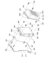
- FIG. 19 is a perspective view of the base 26 attached to the side frame 14.
- FIG. 20 is an exploded perspective view showing the mounting structure of the base 26 to the side frame 14.
- FIG. 21 is a perspective view of the first fixing member 30 and the second fixing member 32 that support the base 26.
- FIG. 22 is a perspective view of the first fixing member 30 and the second fixing member 32 that support the base 26.
- FIG. 23 is a perspective view of the first fixing member 30 as viewed from one side in the vehicle width direction.
- FIG. 24 is a perspective view of the first fixing member 30 as viewed from the other side in the vehicle width direction.
- FIG. 25 is a perspective view of the second fixing member 32 as viewed from one side in the vehicle width direction.
- FIG. 26 is a perspective view of the second fixing member 32 as viewed from the other side in the vehicle width direction.
- the base 26 is disposed above the side frame 14 on the outer side (one end side) in the vehicle width direction, and is fixed to the side frame 14 by a first fixing member 30 and a second fixing member 32.
- first fixing member 30 and second fixing member 32 are fixed to the side frame 14.
- the first fixing member 30 is disposed directly below the air cleaner 100 mounted on the air cleaner mounting portion 26A of the base 26
- the second fixing member 32 is disposed directly below the battery 200 mounted on the battery mounting portion 26B of the base 26.
- the first fixing member 30 has higher rigidity than the second fixing member 32.
- the base 26 has a pair of insertion holes 500 on the rear side in the vehicle's fore-and-aft direction, and a pair of insertion holes 502 on the front side in the vehicle's fore-and-aft direction (see FIG. 20).
- a bolt 504 is inserted into the insertion holes 500 and fastened to the first fixing member 30. This fixes the rear side of the base 26 in the vehicle's fore-and-aft direction to the first fixing member 30.
- a bolt 506 is inserted into the insertion holes 502 and fastened to the second fixing member 32. This fixes the front side of the base 26 in the vehicle's fore-and-aft direction to the second fixing member 32.
- the first fixing member 30 has a first bracket 600.
- the first bracket 600 has a fixing plate portion 602 extending in the vehicle width direction.
- the fixing plate portion 602 has a bolt hole 604 into which the bolt 504 is screwed.
- the fixing plate portion 602 has both edges protruding downward to form a U-shape in cross section.
- a joint piece portion 606 extending downward is formed on one edge of the fixing plate portion 602.
- the first bracket 600 has a connection portion 608 at one end.
- the connection portion 608 is fastened and fixed to an inner portion of a fender panel 612 of the vehicle 10 by a bolt 610.
- the base 26 is connected to the fender panel 612 of the vehicle 10 by the first bracket 600 of the first fixing member 30.
- This first bracket 600 is located below the electronic control unit 300, which is mounted on the base 26 adjacent to the air cleaner 100.
- the first fixing member 30 also has a mount member 620 that supports the first bracket 600 from below.
- This mount member 620 is, for example, a mount that supports a power unit such as an engine or a motor on the side frame 14.
- the mount member 620 has a mount body 622.
- the mount body 622 is formed in a cylindrical shape, and an elastic body 624 is housed inside.
- a pin 628 extending from a fixing seat 626 that is fixed to the engine or motor is inserted into the center of the elastic body 624.
- the cylindrical mount body 622 is a highly rigid member, and the underside of the first bracket 600 and the joint piece 606 are welded and firmly fixed to the circumferential surface of this mount body 622.
- the mount member 620 also has a fixed bracket 630.
- the fixed bracket 630 has a bottom surface portion 632 extending in the front-rear direction of the vehicle, and a pair of side surfaces 634 that stand upright from both edges of the bottom surface portion 632 in the vehicle width direction and are fixed by welding to the peripheral surface of the mount body 622.
- the bottom surface portion 632 of the fixed bracket 630 of the mount member 620 is fastened to the upper surface 14a of the side frame 14 by bolts 636 on both sides of the mount body 622. This fixes the mount member 620 to the upper surface 14a of the side frame 14.
- the second fixing member 32 is composed of a second bracket 700.
- This second bracket 700 has an upper surface portion 702 that extends in the vehicle width direction.
- the upper surface portion 702 is provided with a bolt hole 704 into which the bolt 506 is screwed.
- the second bracket 700 has a pair of side portions 706 extending downward from both edges of the upper surface portion 702 in the vehicle front-rear direction, and these side portions 706 are fixed to the side frame 14. In this way, the second bracket 700 has a pair of side portions 706 extending downward from both edges of the upper surface portion 702 in the vehicle front-rear direction, and is thus U-shaped in cross section when viewed from the vehicle width direction. This allows the second bracket 700 to have appropriate rigidity. In addition, each side portion 706 of the second bracket 700 has folded pieces 710 at the inner end in the vehicle width direction that extend in a direction approaching each other and overlap.
- each side portion 706 of the second bracket 700 has folded pieces 712 at the outer end in the vehicle width direction that extend in a direction approaching each other and overlap. These folded pieces 712 are spot welded to each other and joined. In this way, by forming the folded pieces 710, 712 on the side surface portion 706, the support strength of the base 26 by the second bracket 700 is increased.
- the second bracket 700 has an upper surface fixing portion 720 and a side surface fixing portion 722 at the bottom of each side surface portion 706.
- the upper surface fixing portion 720 is disposed on the upper surface 14a of the side frame 14 and is fastened and fixed to the upper surface 14a of the side frame 14 by a bolt 724.
- the side surface fixing portion 722 is disposed on the side surface 14b of the side frame 14 and is fastened and fixed to the side surface 14b of the side frame 14 by a bolt 726.
- the battery 200 and the electronic control unit 300 are mounted on the base 26, and the electronic control unit 300 is disposed rearward of the battery 200 in the vehicle longitudinal direction and offset in the vehicle width direction (see Figures 1 and 2).
- the battery 200 and the electronic control unit 300 are mounted on the common base 26, the positional relationship between the battery 200 and the electronic control unit 300 is maintained by the base 26 when an impact is applied, and contact of the battery 200 with the electronic control unit 300 can be suppressed.
- the electronic control unit 300 and the side 314 of the mounting bracket 310 are arranged along the vehicle front-rear direction on the outer side of the air cleaner 100 in the vehicle width direction, and the electronic control unit 300 and the mounting bracket 310 are arranged on the outer side in the vehicle width direction, rearward of the battery 200 in the vehicle front-rear direction (see FIG. 2).
- the electronic control unit 300 is arranged on the outer side of the battery 200 in the vehicle width direction together with the side 314 of the mounting bracket 310, so that damage to the electronic control unit 300 caused by the battery 200 moving backward can be more effectively prevented.
- the electronic control unit 300 can be easily attached to the ECU mounting portion 26C of the base 26 (see Figure 13).
- the mounting bracket 310 also has an extension 340 on the rear edge of the side 314 in the vehicle longitudinal direction, and this extension 340 is fastened to a strut housing 346 on the front wheel side of the body of the vehicle 10 (see FIG. 18). This reduces vibration and displacement of the side 314 of the mounting bracket 310, protecting the electronic control unit 300 from vibration, external forces, and the like. Additionally, the extension 340 can absorb impacts applied to the side 314 of the mounting bracket 310, reducing contact of the electronic control unit 300 with surrounding structures.
- the extension portion 340 of the side portion 314 has a bent portion 340a formed midway in the extension direction, and the extension direction is changed at this bent portion 340a (see FIG. 15).
- the bent portion 340a bends, thereby effectively absorbing the impact received by the side portion 314 and protecting the electronic control unit 300.
- the mounting holes 312a for fastening the mounting bracket 310 to the base 26 with stud bolts 316 and nuts 318 are elongated holes extending in the fore-aft direction of the vehicle (see FIG. 13). Therefore, when an impact is applied to the base 26, the fastening position between the base 26 and the bottom 312 of the mounting bracket 310 can be displaced in the longitudinal direction of the mounting holes 312a. This makes it possible to suppress the transmission of impact from the base 26 to the mounting bracket 310 to which the electronic control unit 300 is attached.
- the electronic control unit 300 is covered on the outer side in the vehicle width direction, the front side in the vehicle fore-and-aft direction, and the upper side of the vehicle by the protective bracket 330 (see Figures 15 and 16).
- the protective bracket 330 covers the outer side in the vehicle width direction, the front side in the vehicle fore-and-aft direction, and the upper side of the electronic control unit 300, which are likely to move and come into contact with surrounding structures in the event of a frontal collision of the vehicle 10, to be covered and protected by the protective bracket 330.
- the electronic control unit 300 can be protected by preventing cleaning fluid from being sprayed onto it.
- the connector portion 304 of the electronic control unit 300, to which the connector of the wire harness is connected can be effectively waterproofed.
- the mounting bracket 310 to which the electronic control unit 300 is attached has a bottom 312 that is fixed to the base 26 and is positioned between the base 26 and the air cleaner 100 (see FIG. 17). This allows the attachment location of the bottom 312 to the base 26 to be covered and hidden by the air cleaner 100.
- the mounting bracket 310 to which the electronic control unit 300 is attached is structured so that it cannot be easily removed from the base 26, which prevents the theft of the electronic control unit 300.
- the electronic control unit 300 mounted on the base 26 is disposed on the left side (one end) of the vehicle width, adjacent to the air cleaner 100 in the vehicle width direction (see Figures 1 and 2). This places the air cleaner 100 between the electronic control unit 300 and a power unit such as an engine or motor that is disposed in the center of the vehicle 10 in the vehicle width direction. Therefore, the air cleaner 100 can block the transmission of heat and vibration from the power unit of the vehicle 10 to the electronic control unit 300, reducing the effects of heat and vibration on the electronic control unit 300.
- the first bracket 600 of the first fixing member 30 is disposed below the electronic control unit 300 and extends in the vehicle width direction to connect the base 26 to the fender panel 612 of the vehicle 10, supporting the base 26 from below (see FIG. 20). Therefore, the electronic control unit 300 on the base 26 can be stably supported.
- the first bracket 600 is also supported from below by a mount member 620 fixed to the side frame 14 (see Figures 21 and 22). In this way, the first bracket 600 is supported from below by the high-rigidity mount member 620 that supports a power unit such as an engine or motor to the side frame 14. This increases the support strength of the first bracket 600, and reduces damage to the connection points between the first bracket 600 and the fender panel 612, etc., that may be caused by the load of the base 26 on which the air cleaner 100, battery 200, and electronic control unit 300 are mounted.
- the vehicle structure according to this embodiment further includes a second bracket 700 that is disposed below the battery 200, extends in the vehicle width direction, connects the base 26 to the side frame 14 of the vehicle 10, and supports the base 26 from below (see FIG. 20). This allows the base 26, on which the air cleaner 100, battery 200, and electronic control unit 300 are mounted, to be more firmly supported.
- the support strength of the base 26 can be increased (see FIG. 20). This makes it possible to suppress damage to the connection points between the second bracket 700 and the side frame 14, etc., that would be caused by the load of the base 26 on which the air cleaner 100, the battery 200, and the electronic control unit 300 are mounted.
- the present invention is not limited to the above-described embodiment, and the invention also contemplates the mutual combination of the various components of the embodiment, as well as modifications and applications by those skilled in the art based on the descriptions in the specification and well-known technology, and these are included in the scope of the protection sought.
- the present specification discloses the following: (1) a first in-vehicle device; an electronic control unit disposed rearward in a vehicle front-rear direction with respect to the first vehicle-mounted device and at least a portion of the electronic control unit disposed in a position shifted in a vehicle width direction; a base that is attached to a vehicle body with the first on-board device and the electronic control unit placed thereon;
- a vehicle structure comprising: According to this vehicle structure, the first in-vehicle device and the electronic control unit are mounted on a base, and the electronic control unit is disposed rearward in the vehicle front-rear direction relative to the first in-vehicle device, and at least a portion of the electronic control unit is disposed in a position shifted in the vehicle width direction.
- a mounting bracket for mounting the electronic control unit to the base is further provided.
- the mounting bracket further has an extension portion that extends from the side portion in a vehicle front-rear direction or a vehicle width direction and is attached to the vehicle body.
- the extension portion extending from the side of the mounting bracket is attached to the vehicle body, so vibration and displacement of the side of the mounting bracket can be suppressed, and the electronic control unit can be protected from vibration, external forces, etc.
- the extension portion can absorb impacts applied to the side of the mounting bracket, so contact of the electronic control unit with surrounding structures can be suppressed.
- the bottom portion of the mounting bracket has a mounting hole through which a bolt for fastening to the base is inserted
- the mounting hole is an elongated hole extending in a front-rear direction of the vehicle.
- the mounting hole for fastening the mounting bracket to the base with a bolt is an elongated hole extending in the fore-aft direction of the vehicle, so that when an impact is applied to the base, the fastening position of the bolt between the base and the bottom of the mounting bracket can be displaced in the longitudinal direction of the mounting hole, thereby suppressing the transmission of the impact from the base to the mounting bracket to which the electronic control unit is attached.
- a protective bracket attached to the mounting bracket and covering at least a front side of the electronic control unit in the vehicle longitudinal direction and an outer side in the vehicle width direction.
- a second in-vehicle device is placed on the base at a position adjacent to the electronic control unit in a vehicle width direction,
- the vehicle structure according to any one of (2) to (7), wherein the bottom of the mounting bracket is positioned between the base and the second vehicle-mounted device.
- the bottom of the mounting bracket attached to the base is disposed between the base and the second in-vehicle device, so that the attachment location of the bottom to the base can be covered and hidden by the second in-vehicle device.
- the mounting bracket to which the electronic control unit is attached cannot be easily removed from the base, which makes it possible to prevent theft of the electronic control unit.
- (10) The vehicle structure described in any one of (1) to (9), further comprising a first bracket disposed below the electronic control unit, extending in the vehicle width direction to connect the base and a fender panel of the vehicle, and supporting the base from below.
- the first bracket extends in the vehicle width direction below the electronic control unit, connects the base and the fender panel, and supports the base from below, thereby enabling stably supporting the electronic control unit on the base.
- the first bracket is supported from below by a high-rigidity mounting member that supports a power unit such as an engine or a motor on a vehicle body side frame, etc. This increases the support strength of the first bracket and suppresses damage to the connection between the first bracket and the fender panel, etc., that may be caused by the load of the base on which the first on-board device or the electronic control unit is placed.
- the second bracket extends in the vehicle width direction below the first vehicle-mounted equipment to connect the base and the side frame and support the base from below, thereby enabling the base to be supported more firmly.
- Vehicle 14 Side frame 14a Upper surface of side frame 14b Side surface of side frame 26 Base 100 Air cleaner (second vehicle-mounted device) 200 Battery (first vehicle-mounted device) 300 Electronic control unit 310 Mounting bracket 312 Bottom 312a Mounting hole 314 Side 316 Stud bolt (bolt) 330: Protective bracket 340: Extension portion 340a: Bent portion 346: Strut receiving portion (vehicle body) 600 First bracket 612 Fender panel 620 Mounting member 700 Second bracket
Landscapes
- Engineering & Computer Science (AREA)
- Chemical & Material Sciences (AREA)
- Combustion & Propulsion (AREA)
- Transportation (AREA)
- Mechanical Engineering (AREA)
- Body Structure For Vehicles (AREA)
Abstract
La présente invention propose : une batterie (200) ; une unité de commande électronique (300) qui est, par rapport à la batterie (200), disposée sur le côté arrière dans la direction avant-arrière du véhicule, et qui est au moins partiellement disposée dans une position décalée dans la direction de la largeur du véhicule ; et un socle (26) qui est, dans un état dans lequel la batterie (200) et l'unité de commande électronique (300) y sont placées, à installer dans un cadre latéral (14) qui constitue une carrosserie de véhicule.
Priority Applications (1)
| Application Number | Priority Date | Filing Date | Title |
|---|---|---|---|
| PCT/JP2023/013094 WO2024201871A1 (fr) | 2023-03-30 | 2023-03-30 | Structure de véhicule |
Applications Claiming Priority (1)
| Application Number | Priority Date | Filing Date | Title |
|---|---|---|---|
| PCT/JP2023/013094 WO2024201871A1 (fr) | 2023-03-30 | 2023-03-30 | Structure de véhicule |
Publications (1)
| Publication Number | Publication Date |
|---|---|
| WO2024201871A1 true WO2024201871A1 (fr) | 2024-10-03 |
Family
ID=92903691
Family Applications (1)
| Application Number | Title | Priority Date | Filing Date |
|---|---|---|---|
| PCT/JP2023/013094 Ceased WO2024201871A1 (fr) | 2023-03-30 | 2023-03-30 | Structure de véhicule |
Country Status (1)
| Country | Link |
|---|---|
| WO (1) | WO2024201871A1 (fr) |
Citations (7)
| Publication number | Priority date | Publication date | Assignee | Title |
|---|---|---|---|---|
| JP2000186593A (ja) * | 1998-12-21 | 2000-07-04 | Nissan Motor Co Ltd | 燃料噴射制御ユニットの取付部構造 |
| JP2008037300A (ja) * | 2006-08-08 | 2008-02-21 | Mazda Motor Corp | 自動車の車載部品取付構造 |
| JP2008074304A (ja) * | 2006-09-22 | 2008-04-03 | Mazda Motor Corp | 自動車の制御ユニット取付構造 |
| JP2014182894A (ja) * | 2013-03-18 | 2014-09-29 | Mitsubishi Motors Corp | 車両用バッテリーの取付構造 |
| JP2016168910A (ja) * | 2015-03-12 | 2016-09-23 | 三菱自動車工業株式会社 | バッテリー取付構造 |
| JP2019059378A (ja) * | 2017-09-27 | 2019-04-18 | 三菱自動車工業株式会社 | 車両の前部構造 |
| CN213168294U (zh) * | 2020-08-20 | 2021-05-11 | 恩永(北京)科技股份有限公司 | 汽车前机舱模块化支架 |
-
2023
- 2023-03-30 WO PCT/JP2023/013094 patent/WO2024201871A1/fr not_active Ceased
Patent Citations (7)
| Publication number | Priority date | Publication date | Assignee | Title |
|---|---|---|---|---|
| JP2000186593A (ja) * | 1998-12-21 | 2000-07-04 | Nissan Motor Co Ltd | 燃料噴射制御ユニットの取付部構造 |
| JP2008037300A (ja) * | 2006-08-08 | 2008-02-21 | Mazda Motor Corp | 自動車の車載部品取付構造 |
| JP2008074304A (ja) * | 2006-09-22 | 2008-04-03 | Mazda Motor Corp | 自動車の制御ユニット取付構造 |
| JP2014182894A (ja) * | 2013-03-18 | 2014-09-29 | Mitsubishi Motors Corp | 車両用バッテリーの取付構造 |
| JP2016168910A (ja) * | 2015-03-12 | 2016-09-23 | 三菱自動車工業株式会社 | バッテリー取付構造 |
| JP2019059378A (ja) * | 2017-09-27 | 2019-04-18 | 三菱自動車工業株式会社 | 車両の前部構造 |
| CN213168294U (zh) * | 2020-08-20 | 2021-05-11 | 恩永(北京)科技股份有限公司 | 汽车前机舱模块化支架 |
Similar Documents
| Publication | Publication Date | Title |
|---|---|---|
| US8220576B2 (en) | Front end structure for automobile | |
| JP4292171B2 (ja) | 自動車の前部車体構造 | |
| WO2012090750A1 (fr) | Structure de partie avant de carrosserie de véhicule | |
| JP5195657B2 (ja) | バンパカバー支持構造 | |
| JP3283426B2 (ja) | バンパおよびヘッドランプの取付構造 | |
| CN100450854C (zh) | 支承座装置的安装构造 | |
| JP2000025466A (ja) | ラジエータ及びエアコン用のコンデンサの取付構造 | |
| WO2024201871A1 (fr) | Structure de véhicule | |
| US12291300B2 (en) | Vehicle front structure with headlight cowl brace | |
| JP4081739B2 (ja) | タンクの取付構造 | |
| JP2008037301A (ja) | 自動車の車載部品取付構造 | |
| WO2024201870A1 (fr) | Structure de véhicule | |
| JP2019059378A (ja) | 車両の前部構造 | |
| JP5857655B2 (ja) | 車両のハーネス配設構造 | |
| CN115431741B (zh) | 车辆的悬架支座结构 | |
| KR100383990B1 (ko) | 프론트 앤드 모듈 구조 | |
| JP7121935B2 (ja) | 車体前部構造 | |
| JP2004306776A (ja) | 自動車のトレーラヒッチ装置 | |
| JP3186985B2 (ja) | バンパガードの取付構造 | |
| JPH0580918U (ja) | 自動車用バンパにおけるワイヤハーネス配線構造 | |
| JP5477680B2 (ja) | 車体の前部構造 | |
| JP4992464B2 (ja) | リキッドタンクの取付構造 | |
| JP7782680B2 (ja) | 車両前部構造 | |
| JP3631046B2 (ja) | フェンダの取付構造 | |
| JPH03208780A (ja) | 自動車の前部車体構造及びその組立方法 |
Legal Events
| Date | Code | Title | Description |
|---|---|---|---|
| 121 | Ep: the epo has been informed by wipo that ep was designated in this application |
Ref document number: 23930509 Country of ref document: EP Kind code of ref document: A1 |
|
| DPE1 | Request for preliminary examination filed after expiration of 19th month from priority date (pct application filed from 20040101) | ||
| NENP | Non-entry into the national phase |
Ref country code: DE |
|
| 122 | Ep: pct application non-entry in european phase |
Ref document number: 23930509 Country of ref document: EP Kind code of ref document: A1 |