WO2024202004A1 - Estimation d'un routeur provoquant une défaillance silencieuse - Google Patents
Estimation d'un routeur provoquant une défaillance silencieuse Download PDFInfo
- Publication number
- WO2024202004A1 WO2024202004A1 PCT/JP2023/013540 JP2023013540W WO2024202004A1 WO 2024202004 A1 WO2024202004 A1 WO 2024202004A1 JP 2023013540 W JP2023013540 W JP 2023013540W WO 2024202004 A1 WO2024202004 A1 WO 2024202004A1
- Authority
- WO
- WIPO (PCT)
- Prior art keywords
- slice
- communication
- router
- correlation
- data
- Prior art date
- Legal status (The legal status is an assumption and is not a legal conclusion. Google has not performed a legal analysis and makes no representation as to the accuracy of the status listed.)
- Ceased
Links
Images






Classifications
-
- H—ELECTRICITY
- H04—ELECTRIC COMMUNICATION TECHNIQUE
- H04L—TRANSMISSION OF DIGITAL INFORMATION, e.g. TELEGRAPHIC COMMUNICATION
- H04L41/00—Arrangements for maintenance, administration or management of data switching networks, e.g. of packet switching networks
- H04L41/06—Management of faults, events, alarms or notifications
- H04L41/0677—Localisation of faults
-
- H—ELECTRICITY
- H04—ELECTRIC COMMUNICATION TECHNIQUE
- H04L—TRANSMISSION OF DIGITAL INFORMATION, e.g. TELEGRAPHIC COMMUNICATION
- H04L41/00—Arrangements for maintenance, administration or management of data switching networks, e.g. of packet switching networks
- H04L41/06—Management of faults, events, alarms or notifications
- H04L41/0631—Management of faults, events, alarms or notifications using root cause analysis; using analysis of correlation between notifications, alarms or events based on decision criteria, e.g. hierarchy, tree or time analysis
-
- H—ELECTRICITY
- H04—ELECTRIC COMMUNICATION TECHNIQUE
- H04L—TRANSMISSION OF DIGITAL INFORMATION, e.g. TELEGRAPHIC COMMUNICATION
- H04L41/00—Arrangements for maintenance, administration or management of data switching networks, e.g. of packet switching networks
- H04L41/08—Configuration management of networks or network elements
- H04L41/0893—Assignment of logical groups to network elements
-
- H—ELECTRICITY
- H04—ELECTRIC COMMUNICATION TECHNIQUE
- H04L—TRANSMISSION OF DIGITAL INFORMATION, e.g. TELEGRAPHIC COMMUNICATION
- H04L41/00—Arrangements for maintenance, administration or management of data switching networks, e.g. of packet switching networks
- H04L41/14—Network analysis or design
- H04L41/147—Network analysis or design for predicting network behaviour
-
- H—ELECTRICITY
- H04—ELECTRIC COMMUNICATION TECHNIQUE
- H04L—TRANSMISSION OF DIGITAL INFORMATION, e.g. TELEGRAPHIC COMMUNICATION
- H04L41/00—Arrangements for maintenance, administration or management of data switching networks, e.g. of packet switching networks
- H04L41/14—Network analysis or design
- H04L41/149—Network analysis or design for prediction of maintenance
-
- H—ELECTRICITY
- H04—ELECTRIC COMMUNICATION TECHNIQUE
- H04L—TRANSMISSION OF DIGITAL INFORMATION, e.g. TELEGRAPHIC COMMUNICATION
- H04L41/00—Arrangements for maintenance, administration or management of data switching networks, e.g. of packet switching networks
- H04L41/40—Arrangements for maintenance, administration or management of data switching networks, e.g. of packet switching networks using virtualisation of network functions or resources, e.g. SDN or NFV entities
-
- H—ELECTRICITY
- H04—ELECTRIC COMMUNICATION TECHNIQUE
- H04L—TRANSMISSION OF DIGITAL INFORMATION, e.g. TELEGRAPHIC COMMUNICATION
- H04L43/00—Arrangements for monitoring or testing data switching networks
- H04L43/08—Monitoring or testing based on specific metrics, e.g. QoS, energy consumption or environmental parameters
-
- H—ELECTRICITY
- H04—ELECTRIC COMMUNICATION TECHNIQUE
- H04L—TRANSMISSION OF DIGITAL INFORMATION, e.g. TELEGRAPHIC COMMUNICATION
- H04L43/00—Arrangements for monitoring or testing data switching networks
- H04L43/08—Monitoring or testing based on specific metrics, e.g. QoS, energy consumption or environmental parameters
- H04L43/0805—Monitoring or testing based on specific metrics, e.g. QoS, energy consumption or environmental parameters by checking availability
- H04L43/0817—Monitoring or testing based on specific metrics, e.g. QoS, energy consumption or environmental parameters by checking availability by checking functioning
-
- H—ELECTRICITY
- H04—ELECTRIC COMMUNICATION TECHNIQUE
- H04L—TRANSMISSION OF DIGITAL INFORMATION, e.g. TELEGRAPHIC COMMUNICATION
- H04L43/00—Arrangements for monitoring or testing data switching networks
- H04L43/08—Monitoring or testing based on specific metrics, e.g. QoS, energy consumption or environmental parameters
- H04L43/091—Measuring contribution of individual network components to actual service level
-
- H—ELECTRICITY
- H04—ELECTRIC COMMUNICATION TECHNIQUE
- H04W—WIRELESS COMMUNICATION NETWORKS
- H04W24/00—Supervisory, monitoring or testing arrangements
-
- H—ELECTRICITY
- H04—ELECTRIC COMMUNICATION TECHNIQUE
- H04W—WIRELESS COMMUNICATION NETWORKS
- H04W76/00—Connection management
- H04W76/10—Connection setup
-
- H—ELECTRICITY
- H04—ELECTRIC COMMUNICATION TECHNIQUE
- H04W—WIRELESS COMMUNICATION NETWORKS
- H04W92/00—Interfaces specially adapted for wireless communication networks
- H04W92/04—Interfaces between hierarchically different network devices
- H04W92/14—Interfaces between hierarchically different network devices between access point controllers and backbone network device
-
- H—ELECTRICITY
- H04—ELECTRIC COMMUNICATION TECHNIQUE
- H04L—TRANSMISSION OF DIGITAL INFORMATION, e.g. TELEGRAPHIC COMMUNICATION
- H04L41/00—Arrangements for maintenance, administration or management of data switching networks, e.g. of packet switching networks
- H04L41/14—Network analysis or design
- H04L41/142—Network analysis or design using statistical or mathematical methods
-
- H—ELECTRICITY
- H04—ELECTRIC COMMUNICATION TECHNIQUE
- H04L—TRANSMISSION OF DIGITAL INFORMATION, e.g. TELEGRAPHIC COMMUNICATION
- H04L43/00—Arrangements for monitoring or testing data switching networks
- H04L43/20—Arrangements for monitoring or testing data switching networks the monitoring system or the monitored elements being virtualised, abstracted or software-defined entities, e.g. SDN or NFV
Definitions
- This disclosure relates to estimating the router that is causing a silent failure.
- Patent Document 1 describes deploying multiple network functions (NFs) included in a network service (NS) to a server on which a container-type application execution environment is installed. Patent Document 1 also describes constructing a network slice and monitoring the NFs.
- NFs network functions
- NS network service
- silent failure a degradation in the performance of a functional element (NS, NF, etc.) included in the communication system (so-called silent failure) may occur in communication using a network slice in which the functional element can be used, but it has been difficult to determine the cause of such silent failure.
- This disclosure has been made in consideration of the above-mentioned circumstances, and one of its objectives is to provide a router estimation system and a router estimation method that can accurately estimate the router that is the cause of a silent failure in a network slice.
- the router estimation system includes one or more processors, and at least one of the one or more processors executes a router group data storage process, a correlation reduction degree calculation process, a reduction determination process, a pair number identification process, and a router estimation process.
- a router group data storage process for each of a plurality of network slices constructed in a communication system, router group data indicating the router group constituting the network slice is stored.
- a correlation reduction degree is calculated, which is the degree of reduction in the strength of correlation between a performance index value indicating the performance of a functional element performing one slice communication in one slice communication and a performance index value indicating the performance of a functional element performing the other slice communication in the other slice communication, the correlation reduction degree being associated with a pair of one slice communication, which is slice communication performed by a functional element included in the communication system using a network slice, and the other slice communication, which is slice communication performed by a functional element included in the communication system using a network slice and different from the one slice communication.
- the decrease determination process for each of the multiple pairs, it is determined whether the correlation decrease degree associated with the pair satisfies a given decrease determination condition.
- the pair number identification process for each of the multiple slice communications performed in the communication system, the number of pairs including the slice communication and the correlation decrease degree associated with the pair satisfies the decrease determination condition is identified.
- the router estimation process at least one router included in a router group present on the path of the slice communication, which is identified based on the router group data and in which the number of identified pairs satisfies a given pair number condition, is estimated as the router causing the performance degradation of the functional element related to the slice communication.
- router group data indicating the router group constituting the network slice is stored. Also, a correlation reduction degree is calculated, which is the degree of reduction in the strength of correlation between a performance index value indicating the performance of the functional element performing one slice communication in one slice communication and a performance index value indicating the performance of the functional element performing the other slice communication in the other slice communication, associated with a pair of one slice communication, which is slice communication performed by a functional element included in the communication system using a network slice, and another slice communication, which is a slice communication performed by a functional element included in the communication system using a network slice and different from the one slice communication.
- the correlation reduction degree associated with the pair satisfies a given reduction determination condition. Also, for each of the plurality of slice communications performed in the communication system, the number of pairs including the slice communication and in which the correlation reduction degree associated with the pair satisfies the reduction determination condition is identified. Furthermore, at least one router included in a router group on the path of the slice communication, in which the number of identified pairs, which is identified based on the router group data, satisfies a given pair number condition, is estimated to be the router causing the degradation of the performance of the functional element related to the slice communication.
- FIG. 1 is a diagram illustrating an example of a communication system according to an embodiment of the present invention.
- 1 is a diagram illustrating an example of a communication system according to an embodiment of the present invention.
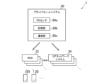
- FIG. 1 is a diagram illustrating an example of a network service according to an embodiment of the present invention.
- FIG. 2 is a diagram showing an example of an association between elements established in a communication system according to an embodiment of the present invention.
- FIG. 2 is a functional block diagram showing an example of functions implemented in a platform system according to an embodiment of the present invention.
- FIG. 2 illustrates an example of a data structure of physical inventory data.
- FIG. 13 is a diagram illustrating an example of segment routing path management data.
- FIG. 11 is a diagram illustrating an example of router group management data.
- FIG. 13 is a diagram illustrating an example of a data structure of correlation degree data.
- FIG. 13 is a diagram illustrating an example of a data structure of correlation reduction degree data.
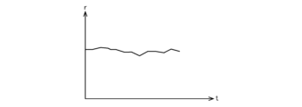
- 10 is a diagram showing an example of a transition of the correlation degree when the correlation decrease degree does not satisfy a decrease determination condition;
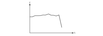
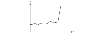
- FIG. 10 is a diagram showing an example of a transition of the correlation degree when the correlation decrease degree satisfies a decrease determination condition;
- FIG. 10 is a diagram showing an example of a transition of the correlation degree when the correlation decrease degree satisfies a decrease determination condition;
- FIG. 13 is a diagram illustrating an example of a data structure of correlation increase degree data.
- FIG. 10 is a diagram showing an example of a transition of the correlation degree when the correlation increase degree satisfies an increase determination condition;
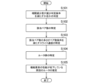
- FIG. FIG. 2 is a flow diagram showing an example of a flow of processing performed in a platform system according to an embodiment of the present invention.
- FIGS. 1 and 2 are diagrams showing an example of a communication system 1 according to one embodiment of the present invention.
- FIG. 1 is a diagram focusing on the locations of the data centers included in the communication system 1.
- FIG. 2 is a diagram focusing on the various computer systems implemented in the data centers included in the communication system 1.
- the data centers included in the communication system 1 are classified into a central data center 10, a regional data center 12, and an edge data center 14.
- central data centers 10 are distributed throughout the area covered by the communication system 1 (for example, within Japan).
- regional data centers 12 are distributed throughout the area covered by the communication system 1. For example, if the area covered by the communication system 1 is the entirety of Japan, one or two regional data centers 12 may be located in each prefecture.
- Each edge data center 14 is capable of communicating with communication equipment 18 equipped with an antenna 16. As shown in FIG. 1, one edge data center 14 may be capable of communicating with several pieces of communication equipment 18.
- the communication equipment 18 may include a computer such as a server computer.
- the communication equipment 18 in this embodiment performs wireless communication with a UE (User Equipment) 20 via the antenna 16.
- the communication equipment 18 equipped with the antenna 16 is provided with, for example, an RU (Radio Unit) as described below.
- the central data center 10, the regional data center 12, and the edge data center 14 each have multiple servers.
- the central data center 10 the regional data centers 12, and the edge data centers 14 are capable of communicating with each other.
- the central data centers 10 are also capable of communicating with each other
- the regional data centers 12 are also capable of communicating with each other
- the edge data centers 14 are also capable of communicating with each other.
- the communication system 1 includes a platform system 30, multiple radio access networks (RANs) 32, multiple core network systems 34, and multiple UEs 20.
- the core network systems 34, the RANs 32, and the UEs 20 work together to realize a mobile communication network.
- the RAN 32 is a computer system equipped with an antenna 16, which corresponds to an eNB (eNodeB) in a fourth generation mobile communication system (hereinafter referred to as 4G) or a gNB (NR base station) in a fifth generation mobile communication system (hereinafter referred to as 5G).
- the RAN 32 in this embodiment is mainly implemented by a group of servers and communication equipment 18 arranged in an edge data center 14.
- a part of the RAN 32 e.g., a distributed unit (DU), a central unit (CU), a virtual distributed unit (vDU), and a virtual central unit (vCU)
- a central data center 10 e.g., a distributed unit (DU), a central unit (CU), a virtual distributed unit (vDU), and a virtual central unit (vCU)
- the core network system 34 is a system equivalent to the EPC (Evolved Packet Core) in 4G and the 5G Core (5GC) in 5G.
- the core network system 34 in this embodiment is implemented mainly by a group of servers located in the central data center 10 and the regional data centers 12.
- the platform system 30 is configured, for example, on a cloud platform, and includes a processor 30a, a storage unit 30b, and a communication unit 30c, as shown in FIG. 2.
- the processor 30a is a program-controlled device such as a microprocessor that operates according to a program installed in the platform system 30.
- the storage unit 30b is, for example, a storage element such as a ROM or RAM, a solid-state drive (SSD), or a hard disk drive (HDD).
- the storage unit 30b stores programs executed by the processor 30a.
- the communication unit 30c is, for example, a communication interface such as a NIC (Network Interface Controller) or a wireless LAN (Local Area Network) module. Note that the communication unit 30c may be implemented with SDN (Software-Defined Networking).
- the communication unit 30c transmits and receives data between the RAN 32 and the core network system 34.
- the platform system 30 is implemented by a group of servers located in the central data center 10. Note that the platform system 30 may also be implemented by a group of servers located in the regional data centers 12.
- the requested network service is constructed in the RAN 32 or the core network system 34. Then, the constructed network service is provided to the purchaser.
- NS network service
- network services such as voice communication services and data communication services are provided to a purchaser who is an MVNO (Mobile Virtual Network Operator).
- the voice communication services and data communication services provided by this embodiment are ultimately provided to a customer (end user) of the purchaser (MVNO in the above example) who uses the UE 20 shown in Figures 1 and 2.
- the end user is able to perform voice communication and data communication with other users via the RAN 32 and the core network system 34.
- the UE 20 of the end user is also able to access a data network such as the Internet via the RAN 32 and the core network system 34.
- an IoT (Internet of Things) service may be provided to an end user who uses a robot arm, a connected car, or the like.
- an end user who uses a robot arm, a connected car, or the like may become a purchaser of the network service related to this embodiment.
- a container-type virtualized application execution environment such as Docker (registered trademark) is installed on the servers located in the central data center 10, the regional data center 12, and the edge data center 14, so that containers can be deployed and run on these servers.
- a cluster consisting of one or more containers generated by such virtualization technology may be constructed.
- a Kubernetes cluster managed by a container management tool such as Kubernetes (registered trademark) may be constructed.
- a processor on the constructed cluster may execute a container-type application.
- the network service provided to the purchaser is composed of one or more functional units (e.g., network functions (NFs)).
- the functional units are implemented as NFs realized by virtualization technology.
- NFs realized by virtualization technology are called VNFs (Virtualized Network Functions). It does not matter what virtualization technology is used for virtualization.
- CNFs Containerized Network Functions
- the network service is described as being implemented by one or more CNFs.
- the functional units in this embodiment may correspond to network nodes.
- FIG. 3 is a schematic diagram of an example of a network service in operation.
- the network service shown in Figure 3 includes NFs as software elements, such as multiple RUs 40, multiple DUs 42, multiple CUs 44 (CU-CP (Central Unit - Control Plane) 44a and CU-UP (Central Unit - User Plane) 44b), multiple AMFs (Access and Mobility Management Functions) 46, multiple SMFs (Session Management Functions) 48, and multiple UPFs (User Plane Functions) 50.
- NFs as software elements, such as multiple RUs 40, multiple DUs 42, multiple CUs 44 (CU-CP (Central Unit - Control Plane) 44a and CU-UP (Central Unit - User Plane) 44b), multiple AMFs (Access and Mobility Management Functions) 46, multiple SMFs (Session Management Functions) 48, and multiple UPFs (User Plane Functions) 50.
- CU-CP Central Unit - Control Plane
- RU 40, DU 42, CU-CP 44a, AMF 46, and SMF 48 correspond to elements of the control plane (C-Plane)
- RU 40, DU 42, CU-UP 44b, and UPF 50 correspond to elements of the user plane (U-Plane).
- the network service may also include other types of NF as software elements.
- the network service is implemented on computer resources (hardware elements) such as multiple servers.
- communication services in a certain area are provided by the network service shown in FIG. 3.
- the multiple RUs 40, multiple DUs 42, multiple CU-UPs 44b, and multiple UPFs 50 shown in FIG. 3 belong to one end-to-end network slice.
- FIG. 4 is a diagram showing a schematic example of an association between elements established in communication system 1 in this embodiment.
- the symbols M and N shown in FIG. 4 represent any integer greater than or equal to 1, and indicate the relationship in numbers between elements connected by a link.
- the elements connected by the link When both ends of a link are a combination of M and N, the elements connected by the link have a many-to-many relationship, and when both ends of a link are a combination of 1 and N or a combination of 1 and M, the elements connected by the link have a one-to-many relationship.
- NS network services
- NF network functions
- CNFC Containerized Network Function Component
- NS corresponds to, for example, a network service composed of multiple NFs.
- NS may correspond to elements of granularity such as 5GC, EPC, 5G RAN (gNB), 4G RAN (eNB), etc.
- NFs correspond to elements with granularity such as RU, DU, CU-CP, CU-UP, AMF, SMF, and UPF.
- NFs correspond to elements with granularity such as MME (Mobility Management Entity), HSS (Home Subscriber Server), S-GW (Serving Gateway), vDU, and vCU.
- MME Mobility Management Entity
- HSS Home Subscriber Server
- S-GW Serving Gateway
- vDU Visitor Gateway
- vCU vCU
- one NS includes one or more NFs.
- one or more NFs are under the control of one NS.
- CNFC corresponds to an element of granularity such as DU mgmt and DU Processing.
- CNFC may be a microservice deployed on a server as one or more containers.
- a certain CNFC may be a microservice that provides some of the functions of DU, CU-CP, CU-UP, etc.
- a certain CNFC may be a microservice that provides some of the functions of UPF, AMF, SMF, etc.
- one NF includes one or more CNFCs. In other words, one or more CNFCs are subordinate to one NF.
- a pod is the smallest unit for managing a Docker container in Kubernetes, for example.
- one CNFC includes one or more pods.
- one or more pods are under the control of one CNFC.
- one pod includes one or more containers.
- one or more containers are subordinate to one pod.
- network slices (NSIs) and network slice subnet instances (NSSIs) are structured hierarchically.
- the NSI can also be considered as an end-to-end virtual line spanning multiple domains (e.g., from the RAN 32 to the core network system 34).
- the NSI may be a slice for high-speed, large-capacity communications (e.g., for enhanced Mobile Broadband (eMBB)), a slice for high-reliability, low-latency communications (e.g., for Ultra-Reliable and Low Latency Communications (URLLC)), or a slice for connecting a large number of terminals (e.g., for massive Machine Type Communication (mMTC)).
- the NSSI can also be a virtual line of a single domain obtained by dividing the NSI.
- the NSSI may be a slice of the RAN domain, a slice of a transport domain such as the Mobile Back Haul (MBH) domain, or a slice of the core network domain.
- MMH Mobile Back Haul
- one NSI includes one or more NSSIs.
- one NSI has one or more NSSIs under it.
- multiple NSIs may share the same NSSI.
- NSSIs and NSs generally have a many-to-many relationship.
- one NF can belong to one or more network slices.
- one NF can be configured with an NSSAI (Network Slice Selection Assistance Information) that includes one or more S-NSSAIs (Sub Network Slice Selection Assist Information).
- NSSAI Network Slice Selection Assistance Information
- S-NSSAIs Sub Network Slice Selection Assist Information
- the S-NSSAI is information associated with a network slice. Note that an NF does not have to belong to a network slice.
- FIG. 5 is a functional block diagram showing an example of functions implemented in the platform system 30 according to this embodiment. Note that it is not necessary for all of the functions shown in FIG. 5 to be implemented in the platform system 30 according to this embodiment, and functions other than the functions shown in FIG. 5 may also be implemented.
- the platform system 30 functionally includes, for example, an operation support system (OSS) unit 60, an orchestration (E2EO: End-to-End-Orchestration) unit 62, a service catalog storage unit 64, a big data platform unit 66, a data bus unit 68, an AI (Artificial Intelligence) unit 70, a monitoring function unit 72, an SDN controller 74, a configuration management unit 76, a container management unit 78, and a repository unit 80.
- the OSS unit 60 includes an inventory database 82, a ticket management unit 84, a fault management unit 86, and a performance management unit 88.
- the E2EO unit 62 includes a policy manager unit 90, a slice manager unit 92, and a life cycle management unit 94. These elements are implemented primarily using the processor 30a, the storage unit 30b, and the communication unit 30c.
- the functions shown in FIG. 5 may be implemented by having processor 30a execute a program that is installed in platform system 30, which is one or more computers, and that includes instructions corresponding to the functions.
- This program may be supplied to platform system 30 via a computer-readable information storage medium, such as an optical disk, magnetic disk, magnetic tape, magneto-optical disk, or flash memory, or via the Internet, for example.
- the functions shown in FIG. 5 may also be implemented in circuit blocks, memory, or other LSIs. Those skilled in the art will understand that the functions shown in FIG. 5 can be realized in various forms, such as hardware only, software only, or a combination thereof.
- the container management unit 78 manages the life cycle of containers. For example, this life cycle management includes processes related to container construction, such as container deployment and configuration.
- the platform system 30 may include multiple container management units 78.
- a container management tool such as Kubernetes and a package manager such as Helm may be installed in each of the multiple container management units 78.
- Each of the multiple container management units 78 may execute container construction, such as container deployment, for a server group (e.g., a Kubernetes cluster) associated with the container management unit 78.
- the container management unit 78 does not need to be included in the platform system 30.
- the container management unit 78 may be provided, for example, in a server managed by the container management unit 78 (i.e., the RAN 32 or the core network system 34), or may be provided in another server that is attached to the server managed by the container management unit 78.
- the repository unit 80 stores, for example, container images of containers included in a functional unit group (e.g., a NF group) that realizes a network service.
- a functional unit group e.g., a NF group
- the inventory database 82 is a database in which inventory information is stored.
- the inventory information includes, for example, information about servers that are placed in the RAN 32 and the core network system 34 and that are managed by the platform system 30.
- inventory data is stored in the inventory database 82.
- the inventory data indicates the configuration of the element group included in the communication system 1 and the current state of the association between the elements.
- the inventory data also indicates the status of the resources managed by the platform system 30 (e.g., the resource usage status).
- the inventory data may be physical inventory data or logical inventory data. Physical inventory data and logical inventory data will be described later.
- FIG. 6 is a diagram showing an example of the data structure of physical inventory data.
- the physical inventory data shown in FIG. 6 corresponds to one server.
- the physical inventory data shown in FIG. 6 includes, for example, a server ID, location data, building data, floor data, rack data, spec data, network data, an operating container ID list, a cluster ID, and the like.
- the server ID included in the physical inventory data is, for example, an identifier of the server associated with the physical inventory data.
- the location data included in the physical inventory data is, for example, data indicating the location (e.g., the address of the location) of the server associated with the physical inventory data.
- the building data included in the physical inventory data is, for example, data indicating the building (e.g., the building name) in which the server associated with the physical inventory data is located.
- the floor data included in the physical inventory data is, for example, data indicating the floor on which the server associated with the physical inventory data is located.
- the rack data included in the physical inventory data is, for example, an identifier for the rack in which the server associated with the physical inventory data is located.
- the spec data included in the physical inventory data is, for example, data indicating the specs of the server associated with the physical inventory data, and the spec data indicates, for example, the number of cores, memory capacity, hard disk capacity, etc.
- the network data included in the physical inventory data is, for example, data that indicates information about the network of the server that corresponds to the physical inventory data, and the network data indicates, for example, the NIC that the server has, the number of ports that the NIC has, the port IDs of the ports, etc.
- the operating container ID list included in the physical inventory data is, for example, data that indicates information about one or more containers operating on a server associated with the physical inventory data, and the operating container ID list indicates, for example, a list of identifiers (container IDs) of instances of the containers.
- the cluster ID included in the physical inventory data is, for example, an identifier of the cluster (e.g., a Kubernetes cluster) to which the server associated with the physical inventory data belongs.
- the logical inventory data includes topology data indicating the current state of associations between multiple elements included in the communication system 1, as shown in FIG. 4.
- the logical inventory data includes topology data including an identifier of a certain NS and an identifier of one or more NFs under the NS.
- the logical inventory data includes topology data including an identifier of a certain network slice and an identifier of one or more NFs belonging to the network slice.
- the inventory data may also include data indicating the current status of geographical relationships and topological relationships between the elements included in the communication system 1.
- the inventory data includes location data indicating the locations where the elements included in the communication system 1 are operating, i.e., the current locations of the elements included in the communication system 1. From this, it can be said that the inventory data indicates the current status of the geographical relationships between the elements (e.g., the geographical proximity between the elements).
- the logical inventory data may also include NSI data indicating information about the network slice.
- the NSI data indicates attributes such as an identifier of an instance of the network slice and a type of the network slice.
- the logical inventory data may also include NSSI data indicating information about the network slice subnet.
- the NSSI data indicates attributes such as an identifier of an instance of the network slice subnet and a type of the network slice subnet.
- the logical inventory data may also include NS data indicating information about NS.
- the NS data indicates attributes such as an NS instance identifier and an NS type.
- the logical inventory data may also include NF data indicating information about NF.
- the NF data indicates attributes such as an NF instance identifier and an NF type.
- the logical inventory data may also include CNFC data indicating information about CNFC.
- the CNFC data indicates attributes such as an instance identifier and a CNFC type.
- the logical inventory data may also include pod data indicating information about a pod included in CNFC.
- the pod data indicates attributes such as a pod instance identifier and a pod type.
- the logical inventory data may also include container data indicating information about a container included in a pod.
- the container data indicates attributes such as a container ID of a container instance and a container type.
- the container ID of the container data included in the logical inventory data and the container ID included in the operating container ID list included in the physical inventory data associate a container instance with the server on which the container instance is running.
- container data may include data indicating an IP address of a container corresponding to the container data.
- NF data may include data indicating an IP address and a host name of an NF indicated by the NF data.
- the logical inventory data may also include data indicating an NSSAI, including one or more S-NSSAIs, that is set in each NF.
- the inventory database 82 also works in conjunction with the container management unit 78 to appropriately grasp the status of resources.
- the inventory database 82 then appropriately updates the inventory data stored in the inventory database 82 based on the latest status of the resources.
- the inventory database 82 updates the inventory data stored in the inventory database 82.
- the service catalog storage unit 64 stores service catalog data.
- the service catalog data may include, for example, service template data indicating the logic used by the life cycle management unit 94.
- This service template data includes information necessary for building a network service.
- the service template data includes information defining NS, NF, and CNFC, and information indicating the correspondence between NS, NF, and CNFC.
- the service template data includes a workflow script for building a network service.
- An example of service template data is an NSD (NS Descriptor).
- An NSD is associated with a network service and indicates the types of multiple functional units (e.g. multiple CNFs) included in the network service.
- the NSD may also indicate the number of each type of functional unit, such as CNFs, included in the network service.
- the NSD may also indicate the file name of a CNFD (described later) related to the CNFs included in the network service.
- the CNFD may indicate the computer resources (e.g., CPU, memory, hard disk, etc.) required by the CNF.
- the CNFD may indicate the computer resources (CPU, memory, hard disk, etc.) required by each of multiple containers included in the CNF.
- the service catalog data may also include information regarding thresholds (e.g., anomaly detection thresholds) that are used by the policy manager unit 90 to compare the calculated performance index values.
- thresholds e.g., anomaly detection thresholds
- the performance index values are described below.
- the service catalog data may also include, for example, slice template data.
- the slice template data includes information required to perform instantiation of a network slice, for example including logic utilized by the slice manager unit 92.
- the slice template data includes information on the "Generic Network Slice Template” defined by the GSMA (GSM Association) ("GSM” is a registered trademark). Specifically, the slice template data includes network slice template data (NST), network slice subnet template data (NSST), and network service template data. The slice template data also includes information indicating the hierarchical structure of these elements, as shown in Figure 4.
- the life cycle management unit 94 creates a new network service in response to a purchase request for an NS by a purchaser.
- the life cycle management unit 94 may, for example, execute a workflow script associated with the network service to be purchased in response to a purchase request. Then, by executing this workflow script, the life cycle management unit 94 may instruct the container management unit 78 to deploy a container included in the new network service to be purchased. Then, the container management unit 78 may obtain a container image of the container from the repository unit 80, and deploy a container corresponding to the container image to a server.
- the life cycle management unit 94 performs, for example, scaling and replacement of elements included in the communication system 1.
- the life cycle management unit 94 may output container deployment and deletion instructions to the container management unit 78.
- the container management unit 78 may then perform processes such as container deployment and container deletion in accordance with the instructions.
- the life cycle management unit 94 is capable of performing scaling and replacement that cannot be handled by a tool such as Kubernetes in the container management unit 78.
- the life cycle management unit 94 may also output an instruction to the SDN controller 74 to create a communication path.
- the life cycle management unit 94 presents the two IP addresses at both ends of the communication path to be created to the SDN controller 74, and the SDN controller 74 creates a communication path connecting these two IP addresses.
- the created communication path may be managed in association with these two IP addresses.
- the life cycle management unit 94 may also output an instruction to the SDN controller 74 to create a communication path between the two IP addresses that is associated with the two IP addresses.
- the slice manager unit 92 performs instantiation of a network slice.
- the slice manager unit 92 performs instantiation of a network slice by executing logic indicated by a slice template stored in the service catalog storage unit 64.
- the slice manager unit 92 is configured to include the functions of the Network Slice Management Function (NSMF) and the Network Slice Sub-network Management Function (NSSMF), for example, as described in the 3GPP (registered trademark) (Third Generation Partnership Project) specification "TS28 533.”
- the NSMF is a function that generates and manages network slices, and provides NSI management services.
- the NSSMF is a function that generates and manages network slice subnets that constitute part of the network slice, and provides NSSI management services.
- the slice manager unit 92 may output configuration management instructions related to instantiation of the network slice to the configuration management unit 76.
- the configuration management unit 76 may then execute configuration management such as settings in accordance with the configuration management instructions.
- the slice manager unit 92 may also present two IP addresses to the SDN controller 74 and output an instruction to create a communication path between these two IP addresses.
- the configuration management unit 76 performs configuration management such as setting up element groups such as NFs, in accordance with configuration management instructions received from the life cycle management unit 94 and slice manager unit 92, for example.
- the SDN controller 74 creates a communication path between two IP addresses associated with a communication path creation instruction received from, for example, the life cycle management unit 94 or the slice manager unit 92.
- the SDN controller 74 may create a communication path between two IP addresses using a known path calculation method such as Flex Algo.
- the SDN controller 74 may use segment routing technology (e.g., SRv6 (Segment Routing IPv6)) to construct NSIs and NSSIs for aggregation routers and servers that exist between communication paths.
- segment routing technology e.g., SRv6 (Segment Routing IPv6)
- the SDN controller 74 may generate NSIs and NSSIs that span multiple NFs to be configured by issuing commands to multiple NFs to be configured to configure a common VLAN (Virtual Local Area Network), and commands to assign the bandwidth and priority indicated in the configuration information to the VLAN.
- VLAN Virtual Local Area Network
- the SDN controller 74 may also perform operations such as changing the maximum bandwidth available for communication between two IP addresses without constructing a network slice.
- the platform system 30 may include multiple SDN controllers 74.
- Each of the multiple SDN controllers 74 may perform processing such as creating communication paths for a group of network devices, such as aggregation routers, associated with the SDN controller 74.
- the SDN controller 74 may appropriately change the created communication path.
- the SDN controller 74 may detect the occurrence of a failure in a network device associated with the SDN controller 74, and in response to the detection, may change the communication path that passes through the network device created by the SDN controller 74 to a communication path that does not pass through the network device.
- the life cycle management unit 94 or the slice manager unit 92 may output a communication path change instruction to the SDN controller 74. Then, the SDN controller 74 may change the communication path created by the SDN controller 74 in accordance with the change instruction.
- the life cycle management unit 94 or the slice manager unit 92 may output to the SDN controller 74 an instruction to change the communication path associated with the identifier of the network device to be excluded from the communication path. Then, in response to receiving the change instruction, the SDN controller 74 may change the communication path created by the SDN controller 74 to a communication path that excludes the network device identified by the identifier associated with the change instruction (i.e., a communication path that does not pass through the network device identified by the identifier associated with the change instruction).
- the monitoring function unit 72 monitors the group of elements included in the communication system 1 according to a given management policy.
- the monitoring function unit 72 may monitor the group of elements according to a monitoring policy specified by a purchaser when purchasing a network service, for example.
- the monitoring function unit 72 performs monitoring at various levels, such as the slice level, the NS level, the NF level, the CNFC level, and the hardware level of the server, etc.
- the monitoring function unit 72 may set a module that outputs metric data in hardware such as a server or in a software element included in the communication system 1 so that monitoring can be performed at the various levels described above.
- an NF may output metric data indicating metrics that are measurable (identifiable) in the NF to the monitoring function unit 72.
- a server may output metric data indicating metrics related to hardware that is measurable (identifiable) in the server to the monitoring function unit 72.
- the monitoring function unit 72 may deploy a sidecar container on the server that aggregates metric data indicating metrics output from multiple containers on a CNFC (microservice) basis.
- This sidecar container may include an agent called an exporter.
- the monitoring function unit 72 may repeatedly execute a process of obtaining metric data aggregated on a microservice basis from the sidecar container at a given monitoring interval, using the mechanism of a monitoring tool such as Prometheus that can monitor container management tools such as Kubernetes.
- the monitoring function unit 72 may, for example, monitor performance indicator values for performance indicators described in "TS 28.552, Management and orchestration; 5G performance measurements” or “TS 28.554, Management and orchestration; 5G end to end Key Performance Indicators (KPIs)". The monitoring function unit 72 may then obtain metric data indicating the performance indicator values being monitored.
- KPIs Key Performance Indicators
- the monitoring function unit 72 executes a process (enrichment) of aggregating metric data in a predetermined aggregation unit, for example, to generate performance index value data indicating the performance index values of the elements included in the communication system 1 in that aggregation unit.
- performance index value data for the gNB is generated by aggregating metric data indicating the metrics of elements (e.g., network nodes such as DU42 and CU44) under the control of the gNB.
- performance index value data indicating communication performance in the area covered by the gNB is generated.
- performance index value data indicating multiple types of communication performance such as traffic volume (throughput) and latency may be generated for each gNB.
- performance index value data indicating the communication performance of a certain element (e.g., DU42) during a specified period may be generated by aggregating metric data indicating the metrics of the element during the specified period.
- the communication performance indicated by the performance index value data is not limited to traffic volume and latency.
- the monitoring function unit 72 outputs the performance index value data generated by the above-mentioned enrichment to the data bus unit 68.
- the data bus unit 68 receives performance index value data output from the monitoring function unit 72. Then, based on the received one or more performance index value data, the data bus unit 68 generates a performance index value file including the one or more performance index value data. Then, the data bus unit 68 outputs the generated performance index value file to the big data platform unit 66.
- elements such as network slices, NS, NF, and CNFC included in the communication system 1, and hardware such as servers, notify the monitoring function unit 72 of various alerts (for example, alerts triggered by the occurrence of a failure).
- the monitoring function unit 72 receives, for example, the above-mentioned alert notification, it outputs alert message data indicating the notification to the data bus unit 68.
- the data bus unit 68 then generates an alert file in which the alert message data indicating one or more notifications are compiled into a single file, and outputs the alert file to the big data platform unit 66.
- the big data platform unit 66 accumulates, for example, performance index value files and alert files output from the data bus unit 68.
- the AI unit 70 has multiple trained machine learning models stored in advance.
- the AI unit 70 uses the various machine learning models stored in the AI unit 70 to perform estimation processing such as future prediction processing of the usage status and service quality of the communication system 1.
- the AI unit 70 may generate estimation result data that indicates the results of the estimation processing.
- the AI unit 70 may perform estimation processing based on the files stored in the big data platform unit 66 and the above-mentioned machine learning model. This estimation processing is suitable for cases where long-term trend predictions are performed infrequently.
- the AI unit 70 can also acquire the performance index value data stored in the data bus unit 68.
- the AI unit 70 can execute an estimation process based on the performance index value data stored in the data bus unit 68 and the above-mentioned machine learning model. This estimation process is suitable for cases where short-term predictions are performed frequently.
- the performance management unit 88 calculates a performance index value (e.g., KPI) based on multiple metric data and on the metrics indicated by these metric data.
- the performance management unit 88 may also calculate a performance index value that is an overall evaluation of multiple types of metrics (e.g., a performance index value related to an end-to-end network slice) that cannot be calculated from a single metric data.
- the performance management unit 88 may generate overall performance index value data that indicates the performance index value that is the overall evaluation.
- the performance management unit 88 may obtain the above-mentioned performance index value file from the big data platform unit 66.
- the performance management unit 88 may also obtain the estimation result data from the AI unit 70. Then, the performance index value such as KPI may be calculated based on at least one of the performance index value file or the estimation result data.
- the performance management unit 88 may also obtain metric data directly from the monitoring function unit 72. Then, the performance index value such as KPI may be calculated based on the metric data.
- the fault management unit 86 detects the occurrence of a fault in the communication system 1 based on at least one of the above-mentioned metric data, the above-mentioned alert notification, the above-mentioned estimation result data, and the above-mentioned overall performance index value data.
- the fault management unit 86 may detect the occurrence of a fault that cannot be detected from a single metric data or a single alert notification, for example, based on a predetermined logic.
- the fault management unit 86 may generate detected fault data indicating the detected fault.
- the fault management unit 86 may obtain metric data and alert notifications directly from the monitoring function unit 72.
- the fault management unit 86 may also obtain performance index value files and alert files from the big data platform unit 66.
- the fault management unit 86 may also obtain alert message data from the data bus unit 68.
- the policy manager unit 90 executes a predetermined determination process based on at least one of the above-mentioned metric data, the above-mentioned performance index value data, the above-mentioned alert message data, the above-mentioned performance index value file, the above-mentioned alert file, the above-mentioned estimation result data, the above-mentioned overall performance index value data, and the above-mentioned detected fault data.
- the policy manager unit 90 may execute an action according to the result of the judgment process. For example, the policy manager unit 90 may output an instruction to construct a network slice to the slice manager unit 92. Also, for example, the policy manager unit 90 may output an instruction to switch the communication path to the slice manager unit 92. Also, the policy manager unit 90 may output an instruction to scale or replace an element to the life cycle management unit 94 according to the result of the judgment process.
- the policy manager unit 90 is capable of acquiring performance index value data stored in the data bus unit 68. The policy manager unit 90 may then execute a predetermined judgment process based on the performance index value data acquired from the data bus unit 68. The policy manager unit 90 may also execute a predetermined judgment process based on the alert message data stored in the data bus unit 68.
- the ticket management unit 84 generates a ticket indicating the content to be notified to the administrator of the communication system 1.
- the ticket management unit 84 may generate a ticket indicating the content of the occurred fault data.
- the ticket management unit 84 may also generate a ticket indicating the value of the performance index value data or metric data.
- the ticket management unit 84 may also generate a ticket indicating the result of the determination made by the policy manager unit 90.
- the ticket management unit 84 notifies the administrator of the communication system 1 of the generated ticket.
- the ticket management unit 84 may, for example, send an email with the generated ticket attached to the email address of the administrator of the communication system 1.
- degradation of performance such as NS or NF (so-called silent failure) may occur without an abnormality such as a failure being detected.
- multiple network slices are constructed.
- a separate router group is set as a component.
- a common router may be set as a component in the multiple network slices.
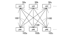
- FIG. 7 is a diagram showing a schematic example of a configuration of a group of functional elements that communicates using one of multiple network slices constructed in the communication system 1 according to this embodiment.
- the network slice shown in FIG. 7 includes multiple segment routing paths 100 as components.
- each of the multiple network slices constructed in the communication system 1 may include one or multiple segment routing paths 100 as components.
- packets are forwarded by segment routing (for example, packets are forwarded by SRv6 or SRMPLS (Segment Routing Multi-Protocol Label Switching)).
- segment routing paths 100 may include a router group as a component.
- a common router may be set as a component in the multiple segment routing paths 100.
- each of the functional elements included in communication system 1 can use one or more network slices that are at least a part of the multiple network slices constructed in communication system 1.
- the functional elements included in communication system 1 are capable of communicating using the network slices available to the functional elements.
- communication performed by a functional element using a network slice available to the functional element will be referred to as slice communication.
- the group of functional elements that communicate using the network slice includes multiple UPFs 50 (50a, 50b, 50c, ...) and multiple gNBs 102 (102a, 102b, 102c, ).
- the gNB 102 includes a DU 42 and a CU 44.
- the group of functional elements that communicate using the network slice may also include other types of functional elements (e.g., an AMF 46, an SMF 48, etc.).
- the router group constituting each of the multiple network slices constructed in the communication system 1 is managed.
- the inventory database 82 may store router group data indicating the router group constituting each of the multiple network slices constructed in the communication system 1.
- the router group data according to this embodiment may include, for example, the segment routing path management data illustrated in FIG. 8 and the router group management data illustrated in FIG. 9.
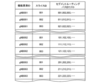
- the segment routing path management data in this embodiment is, for example, data indicating one or more segment routing paths 100 through which packets are forwarded in communication performed by a functional element using a network slice available to the functional element.
- the segment routing path management data includes, for example, a functional element ID, a slice ID, and a segment routing path ID list.
- a functional element ID which is an identifier of a functional element
- a slice ID which is an identifier of a network slice that the functional element can use.
- the segment routing path management data is associated with a segment routing path ID list, which is a list of identifiers (segment routing path IDs) of segment routing paths 100 to which packets are forwarded in communication performed by the functional element using the network slice.
- identifiers of gNB102a, gNB102b, and gNB102c are "gNB001", “gNB002”, and "gNB003", respectively.
- the segment routing path management data shown in FIG. 8 indicates that gNB102a, gNB102b, and gNB102c can each use multiple network slices, including three network slices whose slice IDs are "001,” “002,” and "003,” respectively. Note that the available network slices do not need to be common to all functional elements. The available network slices may differ depending on the functional element.
- network slice A The network slice with a slice ID of "001" will be referred to as network slice A.
- the network slice with a slice ID of "002" will be referred to as network slice B.
- the network slice with a slice ID of "003" will be referred to as network slice C.
- gNB 102a when gNB 102a performs slice communication using network slice A, communication is performed using a segment routing path 100 whose segment routing path ID is one of "001", “002", “003”, etc.
- gNB 102a when gNB 102a performs slice communication using network slice B, communication is performed using a segment routing path 100 whose segment routing path ID is one of "011”, “012”, “013”, etc.
- gNB 102a performs slice communication using network slice C communication is performed using a segment routing path 100 whose segment routing path ID is one of "021", "022", “023”, etc.
- gNB 102b when gNB 102b performs slice communication using network slice A, communication is performed using a segment routing path 100 whose segment routing path ID is one of "101", “102", “103”, etc. In addition, when gNB 102b performs slice communication using network slice B, communication is performed using a segment routing path 100 whose segment routing path ID is one of "111", “112", “113”, etc. In addition, when gNB 102b performs slice communication using network slice C, communication is performed using a segment routing path 100 whose segment routing path ID is one of "121", "122", "123”, etc.
- gNB 102c when gNB 102c performs slice communication using network slice A, communication is performed using a segment routing path 100 whose segment routing path ID is one of "201", “202", “203”, etc. In addition, when gNB 102c performs slice communication using network slice B, communication is performed using a segment routing path 100 whose segment routing path ID is one of "211", “212", “213", etc. In addition, when gNB 102c performs slice communication using network slice C, communication is performed using a segment routing path 100 whose segment routing path ID is one of "221", “222", “223”, etc.
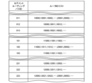
- the router group management data in this embodiment is, for example, data indicating, for each of a plurality of segment routing paths 100, a route group that is a component of the segment routing path 100.
- the router group management data includes, for example, a segment routing path ID and a router ID list.
- the segment routing path ID is an identifier of the segment routing path 100.
- the segment routing path ID corresponds to an element of the segment routing path ID list included in the segment routing path management data.
- the segment routing path ID is associated with a router ID list, which is a list of identifiers (router IDs) of routers that are components of the segment routing path 100 identified by the segment routing path ID.
- the router group management data shown in FIG. 9 indicates that the identifiers of multiple routers constituting a segment routing path 100 having a segment routing path ID of "011” are “10000", “10001”, “10002”, ..., “20001”, “20002”, .... It also indicates that the identifiers of multiple routers constituting a segment routing path 100 having a segment routing path ID of "012” are “10000", “10011”, “10012", .... It also indicates that the identifiers of multiple routers constituting a segment routing path 100 having a segment routing path ID of "013” are "10000", "10021", “10022”, ....
- a router with a router ID of "20001” is a common component of three segment routing paths 100 whose segment routing path IDs are "011", “102", and "223". Also, a router with a router ID of "20002” is a common component of two segment routing paths 100 whose segment routing path IDs are "011" and "102".
- the slice manager unit 92, the life cycle management unit 94, or the SDN controller 74 may change the segment routing path 100, which is a component of the network slice, or the router, which is a component of the segment routing path 100.
- the router group data stored in the inventory database 82 (for example, the segment routing path management data shown in FIG. 8 and the router group management data shown in FIG. 9) is updated.
- the router group data it is possible to identify the segment routing path 100 that is a current component of the network slice, and the router group that is a current component of the segment routing path 100.
- the monitoring function unit 72 monitors the performance of the functional element in slice communication using the network slice for each network slice in which the functional element is available.
- the performance of gNB 102a in slice communication using network slice A, the performance of gNB 102a in slice communication using network slice B, the performance of gNB 102a in slice communication using network slice C, the performance of gNB 102b in slice communication using network slice A, the performance of gNB 102b in slice communication using network slice B, the performance of gNB 102b in slice communication using network slice C, the performance of gNB 102c in slice communication using network slice A, the performance of gNB 102c in slice communication using network slice B, and the performance of gNB 102c in slice communication using network slice C are monitored.
- the monitoring function unit 72 For each network slice in which a functional element is available, the monitoring function unit 72 generates performance index value data indicating the performance of the functional element in the most recent period of a predetermined length (for example, the most recent 15 minutes) in slice communication using the network slice, for example, at a predetermined time interval (for example, 15 minute interval).Then, the monitoring function unit 72 outputs the generated performance index value data to the data bus unit 68, for example, at the time interval.
- a predetermined length for example, the most recent 15 minutes
- performance index value data indicating performance during a certain period when performance index value data indicating performance during a certain period is generated, the performance index value data associated with that period may be output to the data bus unit 68.
- performance index value data associated with period data indicating the start and end of that period may be output to the data bus unit 68.
- the policy manager unit 90 may acquire the output performance index value data in response to the output of the performance index value data to the data bus unit 68.
- the performance indicated by the performance index value data may be, for example, throughput, number of bearer connections, number of attachments, communication speed (bandwidth), etc. Furthermore, an overall value (e.g., a linear combination value of multiple types of performance index values) calculated based on performance index values indicating multiple types of performance (e.g., throughput and number of bearer connections) may be used as the value of the performance index value data. Note that the performance indicated by the performance index value data is not limited to those mentioned above.
- the policy manager unit 90 selects a pair of one slice communication, which is a slice communication performed by any functional element included in the communication system 1 using any network slice, and the other slice communication, which is a slice communication performed by any functional element included in the communication system 1 using any network slice and is different from the one slice communication.
- two different slice communications are selected to form a pair.
- the network slice in which the one slice communication is performed may be the same network slice in which the other slice communication is performed.
- the one slice communication may be slice communication performed by gNB102a using network slice A
- the other slice communication may be slice communication performed by gNB102b using network slice A.
- the network slice in which one slice communication is performed may be a different network slice from the network slice in which the other slice communication is performed.
- the one slice communication may be slice communication performed by gNB 102a using network slice B
- the other slice communication may be slice communication performed by gNB 102b using network slice A.
- the policy manager unit 90 acquires, for example, a plurality of performance index value data each indicating a performance index value indicating the performance of the functional element performing one slice communication in the one slice communication during a period of a specified length of time immediately preceding the one slice communication, and a plurality of performance index value data each indicating a performance index value indicating the performance of the functional element performing the other slice communication in the other slice communication.
- a performance index value data group including multiple performance index value data each indicating a performance index value that indicates the performance of a functional element performing one slice communication in the one slice communication will be referred to as a first performance index value data group.
- a performance index value data group including multiple performance index value data each indicating a performance index value that indicates the performance of a functional element performing the other slice communication in the other slice communication will be referred to as a second performance index value data group.
- the first performance index value data group and the second performance index value data group will each contain 12 performance index value data.
- the period to which each of the multiple performance index value data included in the first performance index value data group is associated is the same period to which each of the multiple performance index value data included in the second performance index value data group is associated.
- the policy manager unit 90 calculates a degree of correlation (e.g., a correlation coefficient) indicating the strength of correlation between the performance index values indicated by the multiple performance index value data included in the first performance index value data group and the performance index values indicated by the multiple performance index value data included in the second performance index value data group.
- a degree of correlation e.g., a correlation coefficient
- the length of the period from the start of the performance index value data with the earliest associated period among the multiple performance index value data groups included in the first performance index value data group to the end of the performance index value data with the latest associated period corresponds to the above-mentioned predetermined time length.
- the length of the period from the start of the performance index value data with the earliest associated period among the multiple performance index value data groups included in the second performance index value data group to the end of the performance index value data with the latest associated period also corresponds to the above-mentioned predetermined time length.
- the calculated correlation degree is associated with the period, which is the predetermined time length.
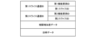
- the policy manager unit 90 generates correlation data, an example of the data structure of which is shown in FIG. 10, based on the calculated correlation.
- the correlation data associates, for example, a first slice communication ID, a second slice communication ID, and date and time data.
- the correlation data is set to, for example, the correlation value calculated as described above.
- the first slice communication ID is an identifier of the one slice communication.
- the first slice communication ID includes, for example, a combination of a first functional element ID, which is an identifier of the functional element performing the one slice communication, and a first slice ID, which is an identifier of the network slice in which the one slice communication is performed.
- the second slice communication ID is an identifier of the other slice communication.
- the second slice communication ID includes, for example, a combination of a second functional element ID, which is an identifier of the functional element that performs the other slice communication, and a second slice ID, which is an identifier of the network slice through which the other slice communication is performed.
- the date and time data is, for example, data indicating a date and time representative of a period associated with the degree of correlation indicated by the correlation data.
- the date and time data may indicate the date and time which is the start or end of the period associated with the degree of correlation.
- the date and time data may indicate the date and time which is the start and end of the period associated with the degree of correlation.
- correlation data is generated for each pair of slice communications performed by any of the multiple functional elements included in the communication system 1 using any of the network slices.
- a pair of slice communications performed by any of the multiple functional elements included in the communication system 1 using any of the network slices will also be referred to as a slice communication pair.
- the timing of generating the correlation data is not particularly limited. For example, each time performance index value data is acquired, correlation data may be generated based on the latest multiple performance index value data. In this case, the periods associated with the correlations indicated by the sequentially generated correlation data will partially overlap.
- the correlation data may also be generated based on the latest multiple performance index value data for each time period corresponding to the length of the period associated with the correlation. For example, in the above example, the correlation data may be generated every three hours. In this case, the periods associated with the correlation indicated by the sequentially generated correlation data do not overlap.
- the policy manager unit 90 calculates a correlation reduction degree, which is the degree of reduction in the strength of correlation between a performance index value indicating the performance of the functional element performing one slice communication in one slice communication and a performance index value indicating the performance of the functional element performing the other slice communication in the other slice communication, which are associated with a pair of one slice communication, which is slice communication performed by one functional element included in the communication system 1 using one network slice, and the other slice communication, which is a slice communication performed by one functional element included in the communication system 1 using one network slice and different from the one slice communication.
- the correlation reduction degree which is the degree of reduction in the strength of correlation of the performance index values, is calculated based on multiple correlation degree data in which the associated first slice communication ID and second slice communication ID are the same and are generated in consecutive order.
- the correlation reduction degree may be the degree of reduction in the correlation coefficient of the performance index values.
- the policy manager unit 90 may calculate the correlation reduction degree value corresponding to the combination of a specific first slice communication ID and a specific second slice communication ID by subtracting the value of the correlation data whose associated date and time data indicates the most recent date from the value of the correlation data whose associated date and time data indicates the second most recent date among the multiple correlation data associated with the specific first slice communication ID and the specific second slice communication ID.
- the policy manager unit 90 may extract a predetermined number of correlation data from among the multiple correlation data associated with the first slice communication ID and the second slice communication ID, in order from the data whose date and time indicated by the most recent date and time data. The policy manager unit 90 may then calculate the average value and standard deviation of the extracted correlation data values.
- the value obtained by subtracting twice the calculated standard deviation from the calculated average value will be expressed as v1.
- the value v1 corresponds to the value (m-2s).
- the policy manager unit 90 may subtract the value of the correlation data whose associated date and time data indicates the latest date and time from the value v1 to calculate the correlation decrease value corresponding to the combination of the first slice communication ID and the second slice communication ID.
- the policy manager unit 90 may also extract correlation data whose values are smaller than the above-mentioned value v1 from a predetermined number of correlation data associated with the first slice communication ID and the second slice communication ID, starting from the data whose associated date and time data indicates the most recent date and time. The policy manager unit 90 may then calculate the sum of the values obtained by subtracting the value of the correlation data from the value v1 for at least one of the extracted correlation data as the correlation reduction value corresponding to the combination of the first slice communication ID and the second slice communication ID.
- the policy manager unit 90 may generate correlation reduction degree data, an example of the data structure of which is shown in FIG. 11, based on the correlation reduction degree calculated as described above.
- the correlation reduction degree data is associated with, for example, a first slice communication ID, a second slice communication ID, and date and time data.
- the correlation reduction data is set to the value of the correlation reduction calculated as described above, for example.
- the first slice communication ID and the second slice communication ID are set to, for example, a first slice communication ID and a specific second slice communication ID corresponding to the degree of correlation reduction, respectively.
- the date and time representative of the plurality of correlation degree data is set as the date and time data value of the correlation reduction degree data.
- the date and time indicated by the date and time data of the most recent of the plurality of correlation degree data associated with the date and time data may be set as the date and time data value of the correlation reduction degree data.
- the date and time indicated by the date and time data of the oldest of the plurality of correlation degree data associated with the date and time data may be set as the date and time data value of the correlation reduction degree data.
- correlation reduction data is generated for each slice communication pair.
- the policy manager unit 90 acquires a correlation reduction degree, which is the degree of reduction in the strength of correlation between a performance index value indicating the performance of the functional element performing one slice communication in one slice communication and a performance index value indicating the performance of the functional element performing the other slice communication in the other slice communication, associated with a pair of, for example, one slice communication, which is slice communication performed by one functional element included in the communication system 1 using one network slice, and the other slice communication, which is slice communication different from the one slice communication, performed by one functional element included in the communication system 1 using one network slice.
- the policy manager unit 90 determines whether or not the correlation reduction degree associated with each of the slice communication pairs satisfies a given reduction determination condition.
- the policy manager unit 90 may acquire the above-mentioned correlation decrease degree data. Then, based on the acquired correlation decrease degree data, the policy manager unit 90 may determine whether or not the value of the correlation decrease degree data satisfies the decrease determination condition.
- the policy manager unit 90 may acquire the latest correlation reduction degree data. The policy manager unit 90 may then determine whether or not the combination of the correlation reduction degree data satisfies the reduction determination condition.
- the correlation decrease degree value is the value obtained by subtracting the correlation decrease degree data value for the most recent date and time indicated by the associated date and time data from the value of the correlation decrease degree data value for the second most recent date and time indicated by the associated date and time data.
- the decrease determination condition may be a condition that "the value of the correlation decrease degree data is equal to or greater than a predetermined value.”
- the decrease determination condition may be a condition that "the values of a predetermined number (e.g., three) of correlation decrease degree data values counted from the most recent date and time indicated by the associated date and time data are all equal to or greater than a predetermined value.”
- the correlation decrease degree value is assumed to be the value obtained by subtracting the value of the correlation decrease degree data for which the associated date and time data indicates the most recent from the above-mentioned value v1.
- the decrease determination condition may be a condition that "the value of the correlation decrease degree data is positive.”
- the decrease determination condition may be a condition that "all of the values of a predetermined number (e.g., three) of correlation decrease degree data from the most recent date and time indicated by the associated date and time data are positive.”
- the correlation decrease value is the sum of values obtained by subtracting the value of at least one piece of extracted correlation data from the value v1.
- the decrease determination condition may be that "the value of the correlation decrease data is equal to or greater than a predetermined number.”
- FIG. 12A is a diagram showing an example of a change in correlation degree when the correlation decrease degree does not satisfy the decrease judgment condition.
- FIG. 12B and FIG. 12C are diagrams showing an example of a change in correlation degree when the correlation decrease degree satisfies the decrease judgment condition.
- the horizontal axis represents the date and time t that represents the period associated with the correlation degree
- the vertical axis represents the correlation degree r.
- a case in which the latest correlation degree is significantly decreased from the previous correlation degree corresponds to a typical example in which the correlation decrease degree satisfies the decrease determination condition.
- the policy manager unit 90 identifies, for each of the multiple slice communications performed in the communication system 1, the number of slice communication pairs that include the slice communication and for which the correlation reduction degree associated with the slice communication pair satisfies the reduction determination condition (hereinafter referred to as the number of relevant pairs).
- the policy manager unit 90 determines whether or not the number of pairs identified for each slice communication performed in the communication system 1 satisfies a given pair number condition.
- the policy manager unit 90 identifies a router group on the path of slice communication where the number of identified slice communication pairs satisfies a given pair number condition based on the router group data. The policy manager unit 90 then estimates at least one router included in the identified router group as the router causing the degradation in performance of the functional element related to the slice communication.
- the path may be a path along which packets are forwarded by segment routing.
- the pair number condition may be "the number of applicable pairs is greater than a predetermined number.”
- the policy manager unit 90 estimates that at least one router included in a group of routers present on a slice communication path in which the number of identified slice communication pairs is greater than a predetermined number is the router causing the degradation of the performance of the functional element related to the slice communication.
- the pair number condition may be "the ratio of the number of slice communication pairs including the slice communication and having a correlation reduction degree associated with the slice communication pair that satisfies the reduction judgment condition to the total number of slice communication pairs including the slice communication, the ratio being greater than a predetermined ratio.”
- the policy manager unit 90 may identify, for each of the multiple slice communications performed in the communication system 1, the ratio of the number of slice communication pairs including the slice communication and having a correlation reduction degree associated with the slice communication pair that satisfies the reduction judgment condition to the total number of slice communication pairs including the slice communication. Then, the policy manager unit 90 may estimate at least one router included in the group of routers present on the path of the slice communication in which the identified ratio is greater than a predetermined ratio, as the router causing the degradation in the performance of the functional element related to the slice communication.
- segment routing path management data For example, assume that slice communication performed by gNB102a using network slice B satisfies the pair number condition.
- a segment routing path ID included in the segment routing path ID list associated with functional element ID "gNB001" and slice ID "002" is identified.
- the segment routing path IDs identified here are, for example, "011”, “012”, “013", etc.
- the router ID list associated with the segment routing path ID "011”, the router ID list associated with the segment routing path ID "012", and the router ID list associated with the segment routing path ID "013" are identified.
- a router ID included in at least one of the router ID lists identified in this manner is identified.
- the group of router IDs including the router IDs identified in this manner will be referred to as a cause candidate router ID group.
- cause candidate router ID group For example, "10000”, “10001”, “10002”, “10011”, “10012”, “10021”, “10022”, “20001”, “20002”, ... are identified as cause candidate router ID groups associated with gNB 102a and network slice B.
- the router identified by the router ID included in the group of candidate cause router IDs identified in this manner is presumed to be the cause of the degradation in performance of gNB102a. Note that all routers identified by the router IDs included in the group of candidate cause router IDs may be presumed to be the routers causing the degradation in performance of gNB102a.
- the policy manager unit 90 may estimate that at least one router included in any of the router groups present on the respective paths of the multiple slice communications is the router causing the degradation in performance of multiple functional elements related to the multiple slice communications.
- slice communication performed by gNB 102a using network slice B slice communication performed by gNB 102b using network slice A, and slice communication performed by gNB 102c using network slice C also satisfy the pair number condition.
- the router ID "20001" which is included in all three groups of router IDs that are potential causes, is presumed to be the router ID of the router that is causing the degradation in the performance of the functional element.
- the slice manager unit 92 may output to the SDN controller 74, for each of one or more routers estimated to be the cause of the degradation of the performance of a functional element, an instruction to change the communication path for the network slice that includes the router as a component. Then, the SDN controller 74 may change the communication path created by the SDN controller 74 in accordance with the change instruction.
- the slice manager unit 92 may output an instruction to change the communication path associated with the router ID of the router to the SDN controller 74 associated with the router presumed to be the cause of the degradation of the performance of the functional element. Then, in response to receiving the change instruction, the SDN controller 74 may change the communication path created by the SDN controller 74 to a communication path that excludes the router identified by the router ID (i.e., a communication path that does not pass through the router).
- an administrator of the platform system 30 or the like may check whether or not an abnormality such as a failure or capacity overflow has occurred for each of the routers presumed to be the cause of the degradation of the performance of the functional elements. Then, the administrator of the platform system 30 or the like may output an instruction to the SDN controller 74 to remove a router in which an abnormality has been confirmed from the communication path. Then, in response to receiving the instruction, the SDN controller 74 may change the communication path created by the SDN controller 74 to a communication path that excludes the router (i.e., a communication path that does not pass through the router).
- the SDN controller 74 or the slice manager unit 92 may update the segment routing path management data shown in FIG. 8 or the router group management data shown in FIG. 9 stored in the inventory database 82 in response to a change in the communication path.
- a degradation in the performance of a functional element included in the communication system 1 may occur in communication using a network slice in which the functional element can be used.
- the number of slice communication pairs that include the slice communication and for which the correlation reduction degree associated with the slice communication pair satisfies the reduction determination condition is identified. Then, at least one router included in the group of routers present on the path of the slice communication in which the number of identified slice communication pairs satisfies a given pair number condition is estimated to be the router causing the degradation in performance of the functional element related to the slice communication.
- the policy manager unit 90 may classify multiple slice communications performed in the communication system 1 into multiple slice communication groups based on the strength of correlation between the performance index values identified for each slice communication pair.
- a number of slice communications carried out in the communication system 1 may be classified into a number of slice communication groups using a general clustering technique.
- classification may be performed such that the latest correlation value for any slice communication pair in which the slice communication included in the slice communication group is a component is greater than a predetermined value.
- the policy manager unit 90 may calculate a correlation reduction degree, which is the degree of reduction in the strength of correlation between a performance index value indicating the performance of a functional element performing one slice communication in one slice communication and a performance index value indicating the performance of a functional element performing the other slice communication in the other slice communication, associated with a pair of one slice communication that is a slice communication included in the slice communication group and another slice communication that is a slice communication included in the slice communication group and different from the one slice communication.
- the policy manager unit 90 may determine, for each pair of slice communications included in the slice communication group, whether the correlation reduction degree associated with the pair satisfies the reduction determination condition corresponding to the slice communication group.
- the policy manager unit 90 may determine a threshold value corresponding to each of the slice communication groups based on the total number of slice communications included in the slice communication group. For example, a value equivalent to 50% of the total number of slice communications, or a value equivalent to 70% of the total number of slice communications, etc. may be determined as the threshold value.
- the policy manager unit 90 may estimate that at least one router included in a group of routers on the path of slice communication, in which the value representing the number of identified slice communication pairs is greater than a threshold value corresponding to the slice communication group including the slice communication pair, is the router causing the degradation in performance of the functional element related to the slice communication.
- the policy manager unit 90 may determine, for each slice communication included in the slice communication group, the ratio of the number of pairs including the slice communication and for which the correlation reduction degree associated with the pair satisfies the reduction determination condition, to the total number of pairs including the slice communication.
- the policy manager unit 90 may estimate that at least one router included in a group of routers present on the path of slice communication in which the identified ratio is greater than a predetermined ratio is the router causing the degradation of the performance of the functional element related to the slice communication.
- the router causing the degradation of the performance of the functional element is estimated for a relatively small number of slice communications, making it possible to reduce the computational load required to estimate the router causing the degradation of the performance of the functional element.
- the policy manager unit 90 may calculate a correlation increase degree, which is the increase degree of the correlation strength between a performance index value indicating the performance of a first functional element in a first slice communication and a performance index value indicating the performance of a second functional element in a second slice communication, which is associated with a pair of slice communications performed by any of a plurality of functional elements included in the communication system 1 using any of the network slices, the pair being a first slice communication performed by a first functional element using a first network slice and a second slice communication performed by a second functional element using a second network slice.
- the correlation increase degree which is the increase degree of the correlation strength of the performance index values
- the correlation increase degree may be calculated based on a plurality of correlation degree data in which the associated first slice communication ID and second slice communication ID are the same and are generated in consecutive order.
- the correlation increase degree may be the increase degree of the correlation coefficient of the performance index values.
- the policy manager unit 90 may calculate the correlation increase degree value corresponding to the combination of a specific first slice communication ID and a specific second slice communication ID by subtracting the value of the correlation degree data whose associated date and time data indicates the second most recent from the value of the correlation degree data whose associated date and time data indicates the most recent, among the multiple correlation degree data associated with the specific first slice communication ID and the specific second slice communication ID.
- the policy manager unit 90 may extract a predetermined number of correlation data from among a plurality of correlation data associated with a specific first slice communication ID and a specific second slice communication ID, in order from the data whose date and time data indicates the most recent date and time.
- the policy manager unit 90 may then calculate the average value and standard deviation of the extracted correlation data values.
- the value obtained by adding twice the calculated standard deviation to the calculated average value will be expressed as v2.
- the value v2 corresponds to the value (m+2s).
- the policy manager unit 90 may calculate the correlation increase degree value corresponding to the combination of the first slice communication ID and the second slice communication ID by subtracting the value v2 from the value of the correlation degree data whose associated date and time data indicates the latest, among the multiple correlation degree data associated with the first slice communication ID and the second slice communication ID.
- the policy manager unit 90 may generate correlation increase data, an example of the data structure of which is shown in FIG. 13, based on the correlation increase calculated as described above.
- the correlation increase data may be associated with, for example, a first slice communication ID, a second slice communication ID, and date and time data.
- the correlation increase data is set to, for example, the value of the correlation increase calculated as described above.
- the first slice communication ID and the second slice communication ID are set to, for example, a first slice communication ID and a second slice communication ID that correspond to the degree of correlation increase, respectively.
- the date and time representative of the plurality of correlation degree data is set as the date and time data value of the correlation increase degree data.
- the date and time indicated by the date and time data of the most recent of the plurality of correlation degree data associated with the date and time data may be set as the date and time data value of the correlation increase degree data.
- the date and time indicated by the date and time data of the oldest of the plurality of correlation degree data associated with the date and time data may be set as the date and time data value of the correlation increase degree data.
- correlation increase data is generated for each slice communication pair.
- the policy manager unit 90 may then acquire a correlation increase degree, which is the degree of increase in the strength of correlation between a performance index value indicating the performance of the functional element performing one slice communication in one slice communication and a performance index value indicating the performance of the functional element performing the other slice communication in the other slice communication, associated with a pair of one slice communication, which is slice communication performed by one functional element included in the communication system 1 using one network slice, and the other slice communication, which is slice communication different from the one slice communication, which is communication performed by one functional element included in the communication system 1 using one network slice.
- the policy manager unit 90 may determine, for each of the slice communication pairs, whether the correlation increase degree associated with that pair satisfies a given increase determination condition.
- the policy manager unit 90 may acquire the above-mentioned correlation increase data. Then, based on the acquired correlation increase data, the policy manager unit 90 may determine whether or not the value of the correlation increase data satisfies the increase determination condition.
- the policy manager unit 90 may also acquire the latest correlation increase data. The policy manager unit 90 may then determine whether or not a combination of the values of the correlation increase data satisfies an increase determination condition.
- the correlation increase value is the value obtained by subtracting the value of the correlation data whose associated date and time data indicates the second most recent from the value of the correlation data whose associated date and time data indicates.
- the increase determination condition may be that "the value of the correlation increase data is greater than or equal to a predetermined value.”
- the increase determination condition may be that "the values of a predetermined number (e.g., three) of correlation increase data items beginning with the most recent date and time indicated by the associated date and time data are all greater than or equal to a predetermined value.”
- the correlation increase value is assumed to be the value of the correlation data for which the associated date and time data indicates the most recent, minus the above-mentioned value v2.
- the increase determination condition may be a condition that "the value of the correlation increase data is positive.”
- the increase determination condition may be a condition that "a predetermined number (e.g., three) of correlation increase data values from the most recent date and time indicated by the associated date and time data are all positive.”
- FIG. 14 is a diagram showing an example of a change in correlation degree when the correlation increase degree satisfies the increase determination condition.
- the horizontal axis represents the date and time t that represents the period associated with the correlation degree
- the vertical axis represents the correlation degree r.
- a case in which the latest correlation degree has increased significantly from the previous correlation degree corresponds to a typical example in which the correlation increase degree satisfies the increase determination condition.
- the policy manager unit 90 may estimate that at least one router included in both a first router group located on the path of one slice communication included in the slice communication pair, and a second router group located on the path of the other slice communication included in the slice communication pair, which are identified based on the router group data, is the router causing the degradation in performance of the functional element related to the slice communication pair.
- the policy manager unit 90 may, for example, identify a first group of routers that exist on the path of the one slice communication. Then, the policy manager unit 90 may, for example, identify a second group of routers that exist on the path of the other slice communication.
- the path may be a path along which packets are forwarded by segment routing.
- the policy manager unit 90 may then estimate that at least one router included in both the first router group and the second router group identified in this manner is the router causing the degradation in the performance of the functional element.
- the router IDs "20001" and “20002”, which are included in both of these groups of candidate router IDs, may be estimated as the router IDs of the routers causing the degradation of the performance of the functional element.
- the policy manager unit 90 may exclude at least one router included in a group of routers on a slice communication path where the number of identified slice communication pairs does not satisfy a given pair number condition from the routers causing the degradation of the performance of the functional element.
- the performance management unit 88 may also generate overall performance index value data indicating the performance of the functional element in slice communication using the network slice for each network slice in which the functional element is available by aggregating the performance index value data generated by the monitoring function unit 72.
- the policy manager unit 90 may then calculate the degree of correlation decrease or increase based on the overall performance index value data generated by the performance management unit 88.
- the router that is causing the deterioration in performance of the functional element may be estimated from among the routers present on the path between RAN 32 and core network system 34 (the path between gNB 102 and UPF 50 in the above example).
- a functional element e.g., UPF 50
- a router that is the cause of the decrease in performance of the functional element may be estimated from among the routers present on the path between the RAN 32 and the core network system 34. In this case, for example, it may be determined whether the correlation decrease degree satisfies the decrease judgment condition based on the performance index value related to the UPF 50. Also, it may be determined whether the correlation increase degree satisfies the increase judgment condition based on the performance index value related to the UPF 50.
- the present invention is also applicable to estimating the router that is the cause of a silent failure in a network slice on a path other than the path between the RAN 32 and the core network system 34.
- a router on the path (midhaul) between CU44 and DU42 that is the cause of a silent failure in the network slice may be estimated.
- the policy manager unit 90 may determine whether or not the correlation decrease degree satisfies the decrease judgment condition for each pair of slice communication performed by the CU 44.
- the policy manager unit 90 may also determine whether or not the correlation increase degree satisfies the increase judgment condition for each pair of slice communication performed by the CU 44. Then, the router that is causing the performance of the CU 44 to decrease may be estimated from among the routers that exist on the path between the CU 44 and the DU 42.
- the value of the performance index value data may be a value indicating the performance of a functional element in the user plane, or a value indicating the performance of a functional element in the control plane.
- the router that is causing the decrease in performance of the functional element from among the group of routers that are components of the user plane may be inferred.
- the router that is causing the decrease in performance of the functional element may be inferred from among the group of routers that are components of the control plane.
- the router that is causing the deterioration in the performance of the functional element may be inferred from among the router group that is a component of the control plane and the user plane.
- a router that is the cause of the degradation in performance of a functional element may be estimated from among the routers that are components of one or more network slice subnet instances. For example, a router that is the cause of the degradation in performance of a functional element may be estimated from among the routers in the backhaul portion on the path. Or, for example, a router that is the cause of the degradation in performance of a functional element may be estimated from among the routers in the midhaul portion on the path.
- the policy manager unit 90 determines whether the correlation reduction degree associated with each slice communication pair satisfies the reduction determination condition for each slice communication pair (S101).
- the policy manager unit 90 identifies, for each slice communication, the number of slice communication pairs that include the slice communication and for which the correlation reduction degree associated with the pair satisfies the reduction determination condition (the number of relevant pairs) (S102).
- the policy manager unit 90 identifies slice communications in which the number of pairs identified in the process shown in S102 satisfies the pair number condition (S103).
- the policy manager unit 90 identifies a group of routers that exist on the path of the slice communication identified in the process shown in S103 (S104).
- the policy manager unit 90 estimates that the router included in the group of routers identified in the process shown in S104 is the router causing the degradation in the performance of the functional element related to the slice communication (S105), and the process shown in this processing example is terminated.
- the functional units according to this embodiment are not limited to those shown in FIG. 3.
- the functional units according to this embodiment do not have to be NFs in 5G.
- the functional units according to this embodiment may be network nodes in 4G, such as eNodeB, vDU, vCU, P-GW (Packet Data Network Gateway), S-GW (Serving Gateway), MME (Mobility Management Entity), HSS (Home Subscriber Server), etc.
- the functional units according to this embodiment may be realized using hypervisor-type or host-type virtualization technology instead of container-type virtualization technology. Furthermore, the functional units according to this embodiment do not need to be implemented by software, and may be implemented by hardware such as electronic circuits. Furthermore, the functional units according to this embodiment may be implemented by a combination of electronic circuits and software.
- a router group data storage means for storing, for each of a plurality of network slices constructed in the communication system, router group data indicating a router group constituting the network slice;
- a correlation reduction degree calculation means for calculating a correlation reduction degree, which is the degree of reduction in the strength of correlation between a performance index value indicating the performance of the functional element performing one slice communication in one slice communication and a performance index value indicating the performance of the functional element performing the other slice communication in the other slice communication, which is associated with a pair of one slice communication, which is slice communication performed by one functional element included in the communication system using one network slice, and the other slice communication, which is communication performed by one functional element included in the communication system using one network slice and different from the one slice communication;
- a decrease determination means for determining, for each of the plurality of pairs, whether or not the correlation decrease degree associated with the pair satisfies a given decrease determination condition;
- a pair number determination means for determining the number of pairs including each slice communication performed in the communication
- the router estimation system further includes a ratio determination means for determining a ratio of the number of pairs including each slice communication performed in the communication system, the number of pairs including the slice communication ...
- the router estimation means estimates at least one router included in a group of routers present on a path of the slice communication in which the identified ratio is greater than a predetermined ratio, as a router causing a decrease in performance of the functional element related to the slice communication.
- the router estimation system according to [1].
- the correlation reduction degree calculation means calculates, for each of the multiple slice communication groups, a correlation reduction degree which is the degree of reduction in the strength of correlation between a performance index value indicating the performance of a functional element performing one slice communication in one slice communication and a performance index value indicating the performance of a functional element performing the other slice communication in the other slice communication, which is associated with a pair of one slice communication which is a slice communication included in the slice communication group and another slice communication which is a slice communication included in the slice communication group and different from the one slice communication, and
- the reduction determination means determines, for each of the plurality of slice communication groups, whether or not the correlation reduction degree associated with each pair of slice communications included in the slice communication group satisfies the reduction determination condition corresponding to the slice communication group.
- the router estimation system according to [1]. [5] Further comprising a threshold determination means for determining a threshold corresponding to each of the plurality of slice communication groups based on the total number of slice communications included in the slice communication group; The router estimation means estimates at least one router included in a router group on the path of the slice communication, in which a value representing the number of identified pairs is greater than the threshold value corresponding to the slice communication group including the pair, as the router causing the degradation of the performance of the functional element related to the slice communication.
- the router estimation system according to [4].
- [6] Further includes a ratio determination means for determining the ratio of the number of pairs including each slice communication included in the slice communication group, in which the correlation reduction degree associated with the pair satisfies the reduction determination condition, to the total number of pairs including the slice communication,
- the router estimation means estimates at least one router included in a group of routers present on a path of the slice communication in which the identified ratio is greater than a predetermined ratio, as a router causing a decrease in performance of the functional element related to the slice communication.
- the router estimation system according to [4].
- the router estimation means estimates at least one router included in any of the router groups on the paths of each of the multiple slice communications as the router causing the degradation in performance of the multiple functional elements related to the multiple slice communications.
- a router estimation system according to any one of claims 1 to 6.
- a correlation increase calculation means for calculating a correlation increase degree, which is the increase degree of the correlation between a performance index value indicating the performance of the functional element performing one slice communication in one slice communication and a performance index value indicating the performance of the functional element performing the other slice communication in the other slice communication, which is associated with a pair of one slice communication, which is slice communication performed by one functional element included in the communication system using one network slice, and the other slice communication, which is communication performed by one functional element included in the communication system using one network slice and different from the one slice communication; and an increase determination means for determining, for each of the plurality of pairs, whether or not the correlation increase degree associated with the pair satisfies a given increase determination condition;
- the router estimation means estimates at least one router included in both a first router group located on the path of one slice communication included in the pair, and a second router group located on the path of the other slice communication included in the pair, identified based on the router group data, as
- the correlation increase degree is an increase degree of the correlation coefficient of the performance index value.
- the router estimation means excludes, from the cause router, at least one router included in a group of routers present on a path of the slice communication where the number of identified pairs does not satisfy the condition for the number of pairs;
- the network slice in which the one slice communication is performed is the same network slice as the network slice in which the other slice communication is performed.
- the network slice in which the one slice communication is performed is different from the network slice in which the other slice communication is performed.
- the functional element is a functional element included in a radio access network of the communication system, the router estimation means estimates the causative router from among a group of routers present on a path between the radio access network and a core network system of the communication system; A router estimation system according to any one of claims 1 to 12.
- the functional element is a functional element included in a core network system of the communication system, the router estimation means estimates the causative router from among a group of routers present on a path between the core network system and a radio access network of the communication system; A router estimation system according to any one of claims 1 to 12.
- the functional element is a CU (Central Unit), The router estimation means estimates the causative router from among a group of routers present on a path between the CU and a DU (Distributed Unit) included in the communication system.
- the correlation reduction degree is a reduction degree of the correlation coefficient of the performance index value.
- the route is a route through which packets are forwarded by segment routing.
- the functional element is a network service or a network function. A router estimation system according to any one of claims 1 to 17.
Landscapes
- Engineering & Computer Science (AREA)
- Computer Networks & Wireless Communication (AREA)
- Signal Processing (AREA)
- Environmental & Geological Engineering (AREA)
- Data Exchanges In Wide-Area Networks (AREA)
Abstract
Priority Applications (4)
| Application Number | Priority Date | Filing Date | Title |
|---|---|---|---|
| EP23930639.2A EP4694541A4 (fr) | 2023-03-31 | 2023-03-31 | Estimation d'un routeur provoquant une défaillance silencieuse |
| US18/574,312 US12634193B2 (en) | 2023-03-31 | Estimation of router that is cause of silent failures | |
| PCT/JP2023/013540 WO2024202004A1 (fr) | 2023-03-31 | 2023-03-31 | Estimation d'un routeur provoquant une défaillance silencieuse |
| JP2025509590A JP7852146B2 (ja) | 2023-03-31 | 2023-03-31 | サイレント障害の原因であるルータの推定 |
Applications Claiming Priority (1)
| Application Number | Priority Date | Filing Date | Title |
|---|---|---|---|
| PCT/JP2023/013540 WO2024202004A1 (fr) | 2023-03-31 | 2023-03-31 | Estimation d'un routeur provoquant une défaillance silencieuse |
Publications (1)
| Publication Number | Publication Date |
|---|---|
| WO2024202004A1 true WO2024202004A1 (fr) | 2024-10-03 |
Family
ID=92904508
Family Applications (1)
| Application Number | Title | Priority Date | Filing Date |
|---|---|---|---|
| PCT/JP2023/013540 Ceased WO2024202004A1 (fr) | 2023-03-31 | 2023-03-31 | Estimation d'un routeur provoquant une défaillance silencieuse |
Country Status (3)
| Country | Link |
|---|---|
| EP (1) | EP4694541A4 (fr) |
| JP (1) | JP7852146B2 (fr) |
| WO (1) | WO2024202004A1 (fr) |
Citations (4)
| Publication number | Priority date | Publication date | Assignee | Title |
|---|---|---|---|---|
| JP2019511787A (ja) * | 2016-03-29 | 2019-04-25 | アンリツ カンパニー | ストリーミング分析法を用いてネットワーク問題の実効顧客影響度をリアルタイムで測定するためのシステム及び方法 |
| US20190364431A1 (en) * | 2017-12-01 | 2019-11-28 | At&T Intellectual Property I, L.P. | Adaptive pairing of a radio access network slice to a core network slice based on device information or service information |
| WO2021171210A1 (fr) | 2020-02-26 | 2021-09-02 | ラクテン・シンフォニー・シンガポール・プライベート・リミテッド | Système de construction de service de réseau et procédé de construction de service de réseau |
| WO2022182272A1 (fr) * | 2021-02-25 | 2022-09-01 | Telefonaktiebolaget Lm Ericsson (Publ) | Procédé d'analyse de réseau de communications à l'aide de modèles d'apprentissage automatique entraînés et informations de topographie de réseau |
Family Cites Families (7)
| Publication number | Priority date | Publication date | Assignee | Title |
|---|---|---|---|---|
| JP4852486B2 (ja) * | 2007-07-06 | 2012-01-11 | 株式会社エヌ・ティ・ティ・ドコモ | トラフィック監視システム |
| US7855952B2 (en) * | 2008-11-20 | 2010-12-21 | At&T Intellectual Property I, L.P. | Silent failure identification and trouble diagnosis |
| JP7669210B2 (ja) * | 2021-06-28 | 2025-04-28 | 株式会社日立情報通信エンジニアリング | 障害検知装置及び障害検知方法 |
| US11778514B2 (en) * | 2021-09-20 | 2023-10-03 | T-Mobile Innovations Llc | Data router connectivity to wireless communication slices |
| US12439331B2 (en) | 2022-03-30 | 2025-10-07 | Rakuten Mobile, Inc. | Communication route determination system and communication route determination method |
| WO2023233470A1 (fr) | 2022-05-30 | 2023-12-07 | 楽天モバイル株式会社 | Estimation de la cause d'une anomalie de réseau |
| JP7620164B2 (ja) | 2022-05-30 | 2025-01-22 | 楽天モバイル株式会社 | ネットワークの異常の原因推定 |
-
2023
- 2023-03-31 WO PCT/JP2023/013540 patent/WO2024202004A1/fr not_active Ceased
- 2023-03-31 EP EP23930639.2A patent/EP4694541A4/fr active Pending
- 2023-03-31 JP JP2025509590A patent/JP7852146B2/ja active Active
Patent Citations (4)
| Publication number | Priority date | Publication date | Assignee | Title |
|---|---|---|---|---|
| JP2019511787A (ja) * | 2016-03-29 | 2019-04-25 | アンリツ カンパニー | ストリーミング分析法を用いてネットワーク問題の実効顧客影響度をリアルタイムで測定するためのシステム及び方法 |
| US20190364431A1 (en) * | 2017-12-01 | 2019-11-28 | At&T Intellectual Property I, L.P. | Adaptive pairing of a radio access network slice to a core network slice based on device information or service information |
| WO2021171210A1 (fr) | 2020-02-26 | 2021-09-02 | ラクテン・シンフォニー・シンガポール・プライベート・リミテッド | Système de construction de service de réseau et procédé de construction de service de réseau |
| WO2022182272A1 (fr) * | 2021-02-25 | 2022-09-01 | Telefonaktiebolaget Lm Ericsson (Publ) | Procédé d'analyse de réseau de communications à l'aide de modèles d'apprentissage automatique entraînés et informations de topographie de réseau |
Non-Patent Citations (1)
| Title |
|---|
| See also references of EP4694541A4 |
Also Published As
| Publication number | Publication date |
|---|---|
| EP4694541A4 (fr) | 2026-05-06 |
| US20250106096A1 (en) | 2025-03-27 |
| JPWO2024202004A1 (fr) | 2024-10-03 |
| JP7852146B2 (ja) | 2026-04-27 |
| EP4694541A1 (fr) | 2026-02-11 |
Similar Documents
| Publication | Publication Date | Title |
|---|---|---|
| US12439331B2 (en) | Communication route determination system and communication route determination method | |
| US12574824B2 (en) | Communication route determination system and communication route determination method | |
| US12457149B2 (en) | Estimation of router that is cause of silent failures | |
| US12615204B2 (en) | Switching control of communication route | |
| US20240248763A1 (en) | Arrangement system and arrangement method | |
| JP7769135B2 (ja) | 通信システムに係る所与の予測目的で用いられる機械学習モデルの決定 | |
| JP7720487B2 (ja) | ネットワーク負荷の予測開始タイミングの制御 | |
| JP7716598B2 (ja) | 通信システムに係る所与の予測目的で用いられる機械学習モデルの決定 | |
| JP7620163B2 (ja) | ネットワークの異常の原因推定 | |
| JP7620164B2 (ja) | ネットワークの異常の原因推定 | |
| US20240281301A1 (en) | Execution platform determination system and execution platform determination method | |
| JP7796941B2 (ja) | サイレント障害の原因であるルータの推定 | |
| JP7852146B2 (ja) | サイレント障害の原因であるルータの推定 | |
| JP7801534B2 (ja) | サイレント障害の原因であるルータの推定 | |
| US12634193B2 (en) | Estimation of router that is cause of silent failures | |
| JP7814556B2 (ja) | アプリケーションが不安定である原因の推定 | |
| JP7812467B2 (ja) | 不安定なアプリケーションのリプレース | |
| US20250103376A1 (en) | Determining whether process included in communication system is unstable |
Legal Events
| Date | Code | Title | Description |
|---|---|---|---|
| WWE | Wipo information: entry into national phase |
Ref document number: 18574312 Country of ref document: US |
|
| 121 | Ep: the epo has been informed by wipo that ep was designated in this application |
Ref document number: 23930639 Country of ref document: EP Kind code of ref document: A1 |
|
| WWP | Wipo information: published in national office |
Ref document number: 18574312 Country of ref document: US |
|
| WWE | Wipo information: entry into national phase |
Ref document number: 2025509590 Country of ref document: JP |
|
| WWE | Wipo information: entry into national phase |
Ref document number: 2023930639 Country of ref document: EP |
|
| NENP | Non-entry into the national phase |
Ref country code: DE |
|
| ENP | Entry into the national phase |
Ref document number: 2023930639 Country of ref document: EP Effective date: 20251031 |
|
| ENP | Entry into the national phase |
Ref document number: 2023930639 Country of ref document: EP Effective date: 20251031 |
|
| ENP | Entry into the national phase |
Ref document number: 2023930639 Country of ref document: EP Effective date: 20251031 |
|
| ENP | Entry into the national phase |
Ref document number: 2023930639 Country of ref document: EP Effective date: 20251031 |
|
| ENP | Entry into the national phase |
Ref document number: 2023930639 Country of ref document: EP Effective date: 20251031 |
|
| ENP | Entry into the national phase |
Ref document number: 2023930639 Country of ref document: EP Effective date: 20251031 |
|
| ENP | Entry into the national phase |
Ref document number: 2023930639 Country of ref document: EP Effective date: 20251031 |
|
| ENP | Entry into the national phase |
Ref document number: 2023930639 Country of ref document: EP Effective date: 20251031 |
|
| WWP | Wipo information: published in national office |
Ref document number: 2023930639 Country of ref document: EP |