WO2024214613A1 - Dispositif d'imagerie endoscopique, endoscope et endoscope à ultrasons - Google Patents
Dispositif d'imagerie endoscopique, endoscope et endoscope à ultrasons Download PDFInfo
- Publication number
- WO2024214613A1 WO2024214613A1 PCT/JP2024/013760 JP2024013760W WO2024214613A1 WO 2024214613 A1 WO2024214613 A1 WO 2024214613A1 JP 2024013760 W JP2024013760 W JP 2024013760W WO 2024214613 A1 WO2024214613 A1 WO 2024214613A1
- Authority
- WO
- WIPO (PCT)
- Prior art keywords
- holder
- connecting member
- imaging device
- endoscope
- signal cable
- Prior art date
- Legal status (The legal status is an assumption and is not a legal conclusion. Google has not performed a legal analysis and makes no representation as to the accuracy of the status listed.)
- Ceased
Links
Images




Classifications
-
- A—HUMAN NECESSITIES
- A61—MEDICAL OR VETERINARY SCIENCE; HYGIENE
- A61B—DIAGNOSIS; SURGERY; IDENTIFICATION
- A61B1/00—Instruments for performing medical examinations of the interior of cavities or tubes of the body by visual or photographical inspection, e.g. endoscopes; Illuminating arrangements therefor
- A61B1/04—Instruments for performing medical examinations of the interior of cavities or tubes of the body by visual or photographical inspection, e.g. endoscopes; Illuminating arrangements therefor combined with photographic or television appliances
Definitions
- the present invention relates to an endoscopic imaging device, an endoscope, and an ultrasonic endoscope that obtain images of an object to be observed, and in particular to an endoscopic imaging device, an endoscope, and an ultrasonic endoscope that have been provided with anti-static measures.
- the endoscope has an insertion portion that is inserted into the body of a subject, and illumination light from an endoscope light source device is irradiated onto an observation object through the insertion portion.
- the endoscope uses an imaging element to capture an image of the observation object illuminated with the illumination light and generate an image signal.
- the processor device processes the image signal generated by the endoscope to generate an observation image to be displayed on a monitor.
- the imaging element is electrically connected to a signal cable via a circuit board formed of a flexible wiring board or the like, and the signal cable is electrically connected to the processor device.
- endoscopes have been provided with measures against static electricity.
- Patent Document 1 describes an endoscope that includes an insertion section having at least a tip portion that is inserted into an object to be examined, a lens unit provided at the tip portion, an imaging element that is arranged on the opposite side of the lens unit to the object to be examined, and a linear conductor whose tip extends toward the lens unit beyond the imaging element and whose base end passes inside the insertion section.
- a long, thin linear conductor is provided along the transmission cable from the outside of the lens unit.
- An object of the present invention is to provide an endoscopic imaging device, an endoscope, and an ultrasonic endoscope that have a simple structure and protect an imaging element from static electricity.
- invention [1] is an endoscopic imaging device for acquiring an image of an object to be observed, comprising a holder for holding an imaging lens directly or a lens barrel having an imaging lens provided therein, an imaging element for receiving light that has passed through the imaging lens and performing photoelectric conversion, a signal cable electrically connected to the imaging element, and a connecting member for connecting the holder and the signal cable, the holder and the connecting member being made of a conductor, and the signal cable comprising a shielding layer for collectively covering a plurality of signal lines and an outer sheath for covering the outside of the shielding layer,
- An endoscopic imaging device in which the outer sheath has an exposed portion at the end of the signal cable on the holder side and covers the shielding layer, the signal cable is held by a connecting member, the tip of the exposed portion of the shielding layer on the holder side is closer to the holder than the tip of the outer sheath on the holder side, the tip of the outer sheath is located closer to the
- Invention [2] is an endoscopic imaging device according to Invention [1], in which the connecting member has a conductive wire, the conductive wire is wound around the outer peripheral surface of the exposed portion of the shielding layer at least once, and the wound conductive wire is connected to the shielding layer by soldering.
- Invention [3] is an endoscopic imaging device according to invention [1] or [2], which has a circuit board electrically connected to the imaging element, the circuit board having a terminal portion, and the shielding layer around which the conductive wire is wound and the terminal portion are electrically connected and fixed by solder.
- Invention [4] is an endoscopic imaging device according to any one of inventions [1] to [3], in which the connecting member is joined to the connecting member on the outside of the connecting member.
- Invention [5] is an endoscopic imaging device as described in Invention [4], in which the connecting member has a narrow portion at the rear end opposite the holder, the length in the width direction perpendicular to the optical axis of the imaging lens being shorter than the tip end on the holder side, and the connecting member is joined to the connecting member at the narrow portion.
- Invention [6] is an endoscopic imaging device according to any one of inventions [1] to [5], having a tip body for fixing a holder or a lens barrel.
- Invention [7] is the endoscopic imaging device according to invention [6], in which the tip body is made of resin.
- the invention [8] is an endoscope having an endoscopic imaging device according to any one of the inventions [1] to [7].
- the invention [9] is an ultrasonic endoscope having the endoscopic imaging device according to the invention [7].
- the present invention provides an endoscopic imaging device, an endoscope, and an ultrasonic endoscope that can protect an imaging element from static electricity with a simple structure.
- FIG. 1 is a schematic diagram showing an example of an endoscope system according to an embodiment of the present invention.
- 1 is a schematic perspective view showing an example of an endoscopic imaging device according to an embodiment of the present invention.
- FIG. 2 is a schematic perspective view showing an example of a connecting member of the endoscopic imaging device according to the embodiment of the present invention.
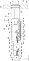
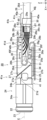
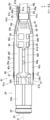
- 1 is a schematic side view showing an example of an endoscopic imaging device according to an embodiment of the present invention.
- 1 is a schematic side view showing an example of an endoscopic imaging device according to an embodiment of the present invention.
- 1 is a schematic top view showing an example of an endoscopic imaging device according to an embodiment of the present invention.
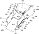
- 1 is a schematic perspective view showing an enlarged view of a main portion of an example of an endoscopic imaging device according to an embodiment of the present invention.
- FIG. 2 is a schematic perspective view showing an example of a signal cable used in the endoscopic imaging device according to the embodiment of the present invention.
- FIG. 11 is a schematic diagram showing another example of the endoscope system according to the embodiment of the present invention.
- 1 is a schematic cross-sectional view showing an example of an ultrasonic endoscope according to an embodiment of the present invention.
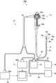
- FIG. 1 is a schematic diagram showing an example of an endoscope system according to an embodiment of the present invention.
- the endoscopic system 10 includes an endoscope 12, a light source device 14, and a processor device 16.
- the endoscopic system 10 has a configuration similar to that of a general endoscope, except for an endoscopic imaging device 20 (see FIG. 2 ) of the endoscope 12, which will be described later.
- the endoscope system 10 may further include a water tank for storing cleaning water or the like, a suction pump for sucking up the aspirated material (including the supplied cleaning water) from within the body cavity, etc. Furthermore, the endoscope system 10 may further include a supply pump for supplying cleaning water from the water tank or a gas such as external air to a duct (not shown) within the endoscope.
- the endoscope 12 has an endoscopic imaging device 20 (see FIG. 2).
- the endoscope 12 has an insertion section that is inserted into the subject, an operating section that is connected to the insertion section, and a universal cord that extends from the operating section, and the insertion section is composed of a tip section, a bending section that is connected to the tip section, and a flexible section that connects the bending section and the operating section.
- the endoscopic imaging device will be described later.
- the tip 12a of the endoscope 12 is provided with an endoscopic imaging device 20 (see FIG. 2) that has an illumination optical system that emits illumination light to illuminate the observation site, or an imaging element and imaging optical system that capture an image of the observation site.
- the bending section is configured to be bendable in a direction perpendicular to the longitudinal axis of the insertion section, and the bending operation of the bending section is controlled by the operating section.
- the flexible section is configured to be relatively flexible so that it can be deformed to follow the shape of the insertion path of the insertion section.
- the operation section is provided with buttons for operating the imaging operation of the endoscopic imaging device 20 (see FIG. 2) at the tip 12a, knobs for operating the bending operation of the bending section, etc.
- the operation section is also provided with an introduction port through which a treatment tool such as an electric scalpel is introduced, and a treatment tool channel is provided inside the insertion section that extends from the introduction port to the tip and through which a treatment tool such as forceps is inserted.
- a connector is provided at the end of the universal cord, and the endoscope 12 is connected via the connector to a light source device 14 that generates illumination light emitted from the illumination optical system at the tip, and a processor device 16 that processes video signals acquired by an endoscopic imaging device 20 (see FIG. 2) at the tip 12a. At least one of signals and power is transmitted between the endoscopic imaging device 20 (see FIG. 2) and the processor device 16 via a group of electric wires.
- the processor unit 16 processes the input video signal to generate video data of the observed area, and displays the generated video data on a monitor (not shown) or records it on a storage medium such as a hard disk.
- the processor unit 16 may be configured with a processor such as a personal computer.
- the light source device 14 generates illumination light such as white light or specific wavelength light consisting of three primary colors such as red (R), green (G), and blue (B), and supplies it to the endoscope 12, where it propagates through a light guide or the like within the endoscope 12 and is emitted from an illumination optical system at the tip of the insertion section of the endoscope 12 to illuminate the area to be observed within the body cavity, in order to capture an image of the area to be observed within the body cavity using the endoscopic imaging device 20 (see Figure 2) of the endoscope 12 and obtain an image signal of the area to be observed.
- illumination light such as white light or specific wavelength light consisting of three primary colors such as red (R), green (G), and blue (B)
- a light guide or a group of electric wires are housed inside the insertion section, the operating section, and the universal cord. Illumination light generated by the light source device 14 is guided to the illumination optical system of the tip portion 12a via the light guide, and the light is emitted from the tip surface 12b of the tip portion 12a.
- FIG. 2 is a schematic perspective view showing an example of an endoscopic imaging device according to an embodiment of the present invention
- Fig. 3 is a schematic perspective view showing a connecting member of the example of the endoscopic imaging device according to an embodiment of the present invention
- Fig. 4 and Fig. 5 are schematic side views showing the example of the endoscopic imaging device according to an embodiment of the present invention
- Fig. 6 is a schematic top view showing the example of the endoscopic imaging device according to an embodiment of the present invention
- Fig. 7 is a schematic perspective view showing an enlarged view of a main part of the example of the endoscopic imaging device according to an embodiment of the present invention. 5 shows the endoscopic imaging device 20 of FIG.
- An endoscopic imaging device 20 shown in Fig. 2 is mounted on a distal end portion 12a of an endoscope 12 of an endoscopic system 10 shown in Fig. 1.
- the endoscopic imaging device 20 is also called a camera head.
- a distal end surface 12b of the distal end portion 12a of the endoscope 12 shown in FIG. 1 is a surface 50a (see FIG. 4) of a distal end body 50 of the endoscopic imaging device 20 (see FIG. 4).
- the endoscopic imaging device 20 shown in Fig. 2 is for acquiring an image of an observation target.
- the endoscopic imaging device 20 has, for example, an imaging lens 23, a lens barrel 22 that holds the imaging lens 23, a holder 24, an imaging element 25, a circuit board 26, a prism 27, and a signal cable 28.
- the endoscopic imaging device 20 also has a connecting member 40.
- the direction parallel to the optical axis C of the imaging lens 23 is defined as the X direction. Of the two directions perpendicular to the optical axis C, one is defined as the Y direction and the other is defined as the Z direction.
- the Y direction corresponds to the width direction of the endoscopic imaging device 20, and the Z direction corresponds to the height direction of the endoscopic imaging device 20.
- the imaging element 25 and electronic components 30, 30a are mounted on a circuit board 26.
- "Mounted” means “electrically connected.”
- the circuit board 26 has at least a first planar portion 26a, a second planar portion 26c connected to the first planar portion 26a by a first bent portion 26b, and a third planar portion 26e connected to the second planar portion 26c by a second bent portion 26d.
- the first planar portion 26a and the third planar portion 26e are parallel to the optical axis C of the imaging lens 23, and the second planar portion 26c is inclined with respect to the optical axis C.
- the second planar portion 26c is inclined at an angle with respect to the optical axis C of the imaging lens 23, and the second planar portion 26c is not parallel to the optical axis C.
- the second planar portion 26c is inclined so that the second bent portion 26d is higher in the Z direction than the first bent portion 26b.
- a signal cable 28 is electrically connected to a rear surface 26h of the third planar portion 26e facing the second planar portion 26c.
- the circuit board 26 is provided on the rear surface 26h with a plurality of connection terminals (not shown) for inputting and outputting signals or power to and from the imaging element 25 and the electronic components 30, 30a.
- a signal line 28a of the signal cable 28 is electrically connected to the connection terminals.
- Prism 27 is, for example, a right-angle prism in which incident surface 27a and exit surface 27b are perpendicular to each other. Prism 27 also has a slope 27c connecting incident surface 27a and exit surface 27b. Slope 27c is the reflective surface of prism 27.
- Prism 27 is an example of an optical member arranged between lens barrel 22 and image sensor 25, and optical members are not limited to prism 27. The arrangement of prism 27 is also not particularly limited. Furthermore, prism 27 may not be necessary depending on the arrangement position of image sensor 25, and a configuration in which another optical member is arranged may be used.
- the imaging lens 23 is an optical element that forms an image of the light incident on the imaging lens 23 on the light receiving surface 25a of the imaging element 25.
- the imaging lens 23 is held by the lens barrel 22.
- the lens barrel 22 is a cylindrical member, and has one or more imaging lenses 23 disposed therein.
- the lens barrel 22 holds one or more imaging lenses 23.
- the lens barrel 22 holds the imaging lenses 23 so that the optical axis C of the imaging lenses 23 is perpendicular to the entrance surface 27a of the prism 27 (see FIG. 5).
- the endoscopic imaging device 20 has, for example, three imaging lenses 23, which are held by the lens barrel 22.
- the configuration of the imaging lens 23 and the lens barrel 22 is not particularly limited.
- the configuration may include one imaging lens 23, or may include two or four or more imaging lenses 23.
- each imaging lens 23 may be a convex lens or a concave lens.
- the imaging element 25 is an imaging element that captures an image by converting the light focused by the imaging lens 23 into an electrical signal through photoelectric conversion.
- the imaging element 25 is a conventionally known imaging element, and may be a CCD (Charge Coupled Device) type image sensor or a CMOS (Complementary Metal Oxide Semiconductor) image sensor.
- the imaging element 25 is disposed on the opposite side of the lens barrel 22 with respect to the holder 24. As shown in Fig. 4, the imaging element 25 is electrically connected to a surface 26f of a first flat portion 26a of the circuit board 26 via, for example, conductive bumps 34. Also, as shown in Fig. 4, the imaging element 25 is mounted on the circuit board 26 so that the light receiving surface 25a is parallel to the optical axis C of the imaging lens 23. Note that mounting means being electrically connected. An underfill layer (not shown) may be provided between the imaging element 25 and the circuit board 26 in order to firmly connect the imaging element 25 and the circuit board 26 .
- the bumps 34 are made of a metal or an alloy. More specifically, the bumps 34 are made of solder. The bumps 34 made of solder are also called solder balls. Note that the bumps 34 are not limited to solder or the like as long as they can electrically connect the imaging element 25 and the circuit board 26. Also, the imaging element 25 and the circuit board 26 may be directly electrically connected to each other.
- the underfill layer also relieves stress that occurs at the joints between the imaging element 25 and the circuit board 26, such as the bumps 34, due to the difference in thermal expansion coefficient between the imaging element 25 and the circuit board 26. The underfill layer firmly connects the imaging element 25 and the circuit board 26, increasing the reliability of the electrical connection, and resulting in a highly reliable endoscopic imaging device 20.
- the underfill agent constituting the underfill layer is not particularly limited, and any agent that is used as a sealing resin between the image sensor 25 and the circuit board 26 can be appropriately used.
- a one-component heat-curing epoxy resin is used as the underfill agent. In this case, after the underfill agent is supplied, it is heated and held at a predetermined temperature to form the underfill layer.
- the circuit board 26 is a board on which the imaging element 25 is mounted.
- electronic components 30, 30a are mounted on the circuit board 26.
- the electronic components 30, 30a are for driving the imaging element 25, and include, but are not limited to, for example, a voltage regulator, a resistor, and a capacitor.
- the voltage regulator is a device that stabilizes the voltage to the imaging element 25, and outputs a constant voltage to the imaging element 25.
- the circuit board 26 is, for example, a flexible board, for example, a flexible printed circuit board.
- the first bent portion 26b and the second bent portion 26d of the circuit board 26 are both formed of curved surfaces.
- the radii of curvature of the first bent portion 26b and the second bent portion 26d may be the same or different. As shown in FIG. 5, the first bent portion 26b has a larger radius of curvature than the second bent portion 26d.
- first bent portion 26b and the second bent portion 26d have a curved surface, they are not limited to being composed of only curved surfaces, and may be composed of, for example, a flat surface and a curved surface.
- the radius of curvature is obtained as follows. First, an image of the circuit board 26 from the side is acquired. Using the acquired image, the relevant locations corresponding to the radius of curvature of the first bent portion 26b and the second bent portion 26d are identified. A curve is fitted to the relevant locations, and the radius of curvature of the curve is measured using a ruler. The measured value is the radius of curvature.
- the measurement of the above-mentioned radius of curvature also includes importing the acquired image of the circuit board 26 into a computer and measuring the radius of curvature of the first bent portion 26b and the second bent portion 26d using software. Fitting a curve to the corresponding portion corresponding to the radius of curvature and measuring the radius of curvature of the curve using a ruler also includes performing the measurement using software on a computer.
- the imaging element 25 is mounted on a surface 26f of the first flat portion 26a as shown in Fig. 4.
- an electronic component 30 is also mounted on the surface 26f of the first flat portion 26a.
- the electronic components 30, 30a are mounted on the back surface 26g of the second flat surface 26c, which faces the front surface 26f of the first flat surface 26a. Since the second flat surface 26c is inclined with respect to the first flat surface 26a, a wide space is created between the first flat surface 26a and the second flat surface 26c. Therefore, a large-sized electronic component 30a can be mounted.
- the electronic component 30a mounted on the second bent portion 26d side is taller than the electronic component 30 mounted on the first bent portion 26b side.
- connection terminals are provided on the back surface 26h of the third planar portion 26e facing the second planar portion 26c.
- the electronic components 30 are mounted on the front surface 26i of the third planar portion 26e.
- the arrangement of the image sensor 25, the electronic components 30, 30a, the connection terminals, etc. on the circuit board 26 is not particularly limited.
- a signal line 28a (see FIG. 4) of a signal cable 28 is electrically connected to a connection terminal (not shown) provided on a back surface 26h (see FIG. 5) of the third flat surface 26e of the circuit board 26, electrically connecting the image pickup element 25 and the signal cable 28. Light is converted into an electrical signal by the image pickup element 25, and this electrical signal is transmitted via the signal cable 28.
- the signal cable 28 is inserted through the insertion portion, operation portion, universal cord, etc. of the endoscope, and is electrically connected to the processor device 16 (see FIG. 1).
- the circuit board 26 has a planar terminal portion 63 provided on the back surface 26h of the third planar portion 26e, on the opposite side of the holder 24 from the connection terminal (not shown).
- the planar terminal portion 63 has, for example, a trapezoidal shape when viewed from the front surface 26i side of the third planar portion 26e, but the shape is not particularly limited. Moreover, the terminal portion 63 is electrically connected to a ground layer (not shown) of the circuit board 26. The terminal portion 63 is called a pad. As described below, the terminal portion 63 is electrically connected to the shield layer 28c of the signal cable 28 via the connection member 60. For this reason, the terminal portion 63 is preferably provided at a position facing an exposed portion 28e of the shield layer 28c of the signal cable 28, which will be described later.
- the signal cable 28 includes, for example, a plurality of signal wires 28a, a coating layer 28b that coats each of the signal wires 28a, a shielding layer 28c that is provided around the entirety of the signal wires 28a coated with the coating layer 28b and covers the signal wires 28a collectively, and an outer jacket 28d that coats the outside of the shielding layer 28c.
- the signal cable 28 is a multi-core cable in which a plurality of signal wires 28a are bundled together, a shielding layer 28c is provided around the signal wires 28a, and the signal cable 28 is housed in a cylindrical outer sheath 28d.
- the shielding layer 28c is, for example, grounded.
- the outer cover 28d forms the outer periphery of the signal cable 28.
- the covering layer 28b, the shield layer 28c, and the outer cover 28d are, for example, cylindrical.
- the shield layer 28c of the signal cable 28 is called the shield.
- the signal cable 28 has, for example, five signal wires 28a.
- the number of signal wires 28a depends on the configuration of the endoscopic imaging device 20 and is not particularly limited, and may be two, three, four, or six or more.
- the outer cover 28d is provided with an exposed portion 28e and covers the shield layer 28c.
- the shield layer 28c has the exposed portion 28e on the end 29 side.
- the holder 24 side refers to the imaging lens 23 side, that is, the surface 50a side of the tip body 50 shown in FIG.
- the signal cable 28 is held by the connecting member 40 and housed within the connecting member 40.
- a tip 29b on the holder 24 side of an exposed portion 28e of a shield layer 28c of the signal cable 28 is located closer to the holder 24 than a tip 29a on the holder 24 side of an outer sheath 28d of the signal cable 28.
- a tip 29a of the outer cover 28d of the signal cable 28 on the holder 24 side is located closer to the holder 24 than a rear end 40j of the connecting member 40 on the opposite side to the holder 24.
- the outer cover 28d of the signal cable 28 is housed in an interior 41d of the connecting member 40.
- connection member 60 The exposed portion 28e of the shielding layer 28c of the signal cable 28 and the coupling member 40 are electrically connected by the connection member 60.
- the holder 24 and the coupling member 40 are made of a conductor as described below, and the holder 24, the exposed portion 28e of the shielding layer 28c of the signal cable 28, and the coupling member 40 are electrically connected by the connection member 60.
- the second electrical resistance between the holder 24 and the connecting member 40 is smaller than the first electrical resistance between the holder 24 and the imaging element 25. Therefore, static electricity flows preferentially between the holder 24 and the connecting member 40, which has a smaller electrical resistance, than between the holder 24 and the imaging element 25. This prevents static electricity from flowing to the imaging element 25, and the imaging element 25 can be protected from static electricity. Moreover, the above-mentioned protection of the imaging element 25 from static electricity can be achieved with a simple structure in which the exposed portion 28e of the shield layer 28c and the connecting member 40 are electrically connected by the connecting member 60. The first electrical resistance between the holder 24 and the imaging element 25 and the second electrical resistance between the holder 24 and the connecting member 40 are measured using a tester. Specifically, the shield layer 28c is provided with a connection member 60, which will be described later.
- the prism 27 is disposed between the lens barrel 22 and the image sensor 25 via a cover glass 31.
- the prism 27 guides light that has passed through the imaging lens 23 to the light receiving surface 25a of the image sensor 25.
- the prism 27 bends the light that has passed through the imaging lens 23 held in the lens barrel 22 by, for example, 90° at the inclined surface 27c, i.e., the reflecting surface, to change the optical path, and guides the light to the light receiving surface 25a of the image sensor 25.
- the transmitted light that has passed through the imaging lens 23 enters the prism 27, is reflected by the inclined surface 27c of the prism 27, i.e., the reflecting surface, and is incident on the light receiving surface 25a of the image sensor 25.
- the prism 27 is disposed so that the entrance surface 27a faces the surface on the base end side of the lens barrel 22.
- the prism 27 is also disposed so that the exit surface 27b faces the light receiving surface 25a of the image sensor 25.
- the prism 27 is disposed on the cover glass 31 so that the exit surface 27b faces the cover glass 31.
- the cover glass 31 is disposed on the light receiving surface 25a of the image sensor 25 to protect the light receiving surface 25a.
- the prism 27 and the cover glass 31 are bonded together with, for example, a light curing adhesive. Note that the cover glass 31 may be omitted.
- the imaging element 25 may be configured to be bonded to the holder 24 instead of to the prism 27 .
- the holder 24 is a member that holds the lens barrel 22 and the prism 27, and is made of a conductor.
- the conductor that constitutes the holder 24 is, for example, a metal or an alloy.
- the holder 24 is a substantially cylindrical member, and the lens barrel 22 is fitted into the inside of the cylindrical portion to hold the lens barrel 22.
- the inner surface of the holder 24 and the outer peripheral surface of the lens barrel 22 are fixed by adhesive.
- Various known adhesives used in conventional endoscopes can be used as the adhesive for bonding the holder 24 and the lens barrel 22. The same applies to adhesives for bonding other members together.
- the holder 24 has a polygonal flange portion 24b on the end surface on the base end side of the mounting tube portion 24a.
- a restricting member 24d is provided on each of both ends of the flange portion 24b in the Y direction.
- the restricting member 24d is, for example, a convex member.
- the restricting member 24d has, for example, a rectangular outer shape.
- an arm portion 40c of the connecting member 40 is engaged with the restricting member 24d.
- Prism 27 is disposed between regulating members 24d, and incident surface 27a abuts flange portion 24b while sandwiched between regulating members 24d. This positions prism 27 in the X direction.
- Holder 24 holds lens barrel 22 and prism 27 in predetermined positions, thereby fixing the relative positions of lens barrel 22 and prism 27, i.e., the relative position of lens barrel 22 and light receiving surface 25a of image sensor 25. Exit surface 27b of prism 27 faces image sensor 25.
- the lens barrel 22 is adhesively fixed to the holder 24 after the relative position with respect to the optical axis C direction of the imaging lens 23 is adjusted so that the focus is on the light receiving surface 25a of the imaging element 25.
- the optical axis C direction is the extension direction of the optical axis C of the imaging lens 23.
- the optical axis C direction of the imaging lens 23 is parallel to the X direction.
- the connecting member 40 connects the holder 24 and the signal cable 28, and is made of a conductor.
- the conductor constituting the connecting member 40 is, for example, a metal or an alloy.
- a metal material having high thermal conductivity is preferable.
- stainless steel and copper alloy are preferable for the connecting member 40.
- electrical resistance copper alloy with low electrical resistance is preferable for the connecting member 40.
- the connecting member 40 holds and houses the signal cable 28 in the interior 41d.
- the connecting member 40 is a member formed by bending a single plate material, for example, as shown in FIG. 3. Specifically, the connecting member 40 has a shape in which a single plate material is bent at two bending portions 40k, 40m that extend in the direction of the optical axis C. Therefore, the cross section of the connecting member 40 perpendicular to the direction of the optical axis C is approximately C-shaped.
- the connecting member 40 has a flat bottom portion 40a formed by bending a single plate material, and a flat holding portion 40b continuous with the bottom portion 40a.
- the holding portion 40b side of the connecting member 40 is defined as a rear end 41a.
- the rear end 41a is the end opposite the holder 24.
- the signal cable 28 is held inside the holding portion 40b.
- the flat plate-shaped holding portions 40b facing each other with an opening in between are each provided with an arm portion 40c.
- the connecting member 40 has a pair of arm portions 40c. The arm portion 40c is bent outward from the holding portion 40b at the rear end 41a side and then extends linearly.
- the pair of arm portions 40c are spaced apart from each other at the front end 41b wider than at the rear end 41a, and this space is appropriately determined in accordance with the regulating member 24d of the holder 24 shown in FIG. 2.
- an opening 40d is provided at the front end 41b of each arm portion 40c.
- the maximum length in the Y direction from the outside of one arm portion 40c to the outside of the other arm portion 40c is the maximum width of the connecting member 40.
- the connecting member 40 has a narrow portion 41c at its rear end 41a opposite the holder 24, the length in the width direction perpendicular to the optical axis C of the imaging lens 23, i.e., the length in the Y direction, being shorter than the tip 41b on the holder 24 side.
- the holding portions 40b facing each other in the Y direction are bent at a bent portion 40k on the tip end 41b side, expanded in the width direction, and connected to the arm portion 40c.
- the bent portion 40k is a connection portion between the holding portions 40b and the arm portion 40c.
- the holding portion 40b is bent at a bent portion 40m on the rear end 41a side, and has a surface 40p on the rear end 41a side that is parallel to the optical axis C.
- the parallel surfaces 40p face each other in the Y direction.
- the opposing parallel surfaces 40p and the bottom 40a form a narrow width portion 41c.
- the holding portion 40b is provided with a window portion 40n that reaches halfway in the Z direction from the bottom portion 40a.
- the window portion 40n is an opening that penetrates the holding portion 40b.
- the window portion 40n is provided in a range that includes the bent portion 40m.
- an opening 40d of the arm portion 40c engages with the regulating member 24d of the holder 24.
- the opening 40d is formed, for example, by cutting out a part of the arm portion 40c in a rectangular shape.
- the opening 40d may have the same size and shape as the outer shape of the restricting member 24d.
- the above-mentioned shape of the opening 40d being the same size and shape as the outer shape of the restricting member 24d includes a generally acceptable error range in the relevant technical field. Therefore, the opening 40d and the restricting member 24d may have any of a so-called clearance fit, transition fit, and interference fit.
- "same size and shape" includes the error range generally accepted in the relevant technical field, as described above.
- each arm portion 40c has, for example, an edge 40e parallel to the second planar portion 26c of the circuit board 26.
- the edge 40e is located above the second planar portion 26c in the Z direction, and when the circuit board 26 is covered from above with the connecting member 40, the second planar portion 26c of the circuit board 26 is exposed.
- a cover portion 40f is provided on each arm portion 40c. As shown in FIG. 6, the cover portions 40f are not connected to each other in the Y direction, and there is a gap 40g.
- the cover portion 40f is partially provided in the X direction, and there is an opening 40h on the tip 41b side of the cover portion 40f.
- the cover portion 40f is a member disposed on the surface 26i of the third flat portion 26e of the circuit board 26.
- the gap 40g and the opening 40h in the cover portion 40f prevent contact with the electronic component 30 disposed on the surface 26i of the third flat portion 26e.
- the connecting member 40 covers a part of the third flat portion 26e of the circuit board 26, the prism 27, and the tip portion of the signal cable 28, and serves as a cover member for the circuit board 26, the prism 27, and the signal cable 28. Furthermore, the connecting member 40 also functions as a protective member for the circuit board 26, the prism 27, and the signal cable 28.
- the connecting member 40 is not particularly limited to the configuration shown in FIG. 3, and may have a configuration without the cover portion 40f, or the gap 40g of the cover portion 40f may be wider.
- the configuration has the openings 40d of the pair of arms 40c and the engaging portions 41 that engage with the restricting member 24d of the holder 24, so that the openings 40d fit into the convex restricting member 24d, thereby shortening the length of the endoscopic image pickup device 20 in the Y direction perpendicular to the optical axis C, thereby preventing the size of the endoscopic image pickup device 20 from becoming large.
- the holder 24 and the connecting member 40 can be firmly fixed to each other.
- the length of the endoscopic imaging device 20 in the Y direction perpendicular to the optical axis C can be made shorter, and this configuration allows the endoscopic imaging device 20 to be made smaller.
- the pair of arm portions 40c are preferably bent so that the front ends 41b of the arm portions 40c are closer to each other than the rear ends 41a of the arm portions 40c.
- the pair of arm portions 40c are preferably bent in a closing direction. This allows the openings 40d of the arm portions 40c to be fitted into the restricting member 24d of the holder 24 by spreading the arm portions 40c once, making assembly easy.
- the pair of arm portions 40c are preferably bent so that the front ends 41b of the arm portions 40c are closer to each other than the rear ends 41a of the arm portions 40c, but this may be the case in the state of the components before assembly.
- the arm portion 40c is provided with the opening 40d which penetrates the arm portion 40c, but the present invention is not limited to this.
- the arm portion 40c may be a recessed portion having a bottom without penetrating the arm portion 40c.
- the signal cable 28 is attached to the inside of the holding portion 40b and held in the connecting member 40.
- the method of attaching the signal cable 28 is not particularly limited as long as the signal cable 28 does not come off the holding portion 40b and the signal line 28a does not come off when the endoscope is in use, and for example, the signal cable 28 can be attached to the connecting member 40 using an adhesive as described below.
- the two regulating members 24d have the same size and shape, i.e., are congruent, as described above, but may have different sizes and shapes.
- the shape of the restricting member 24d (protruding portion) in the holder 24 is not particularly limited to the above-mentioned quadrangle, but may be a circle, an ellipse, or a polygon such as a triangle, a pentagon, or a hexagon, or may be a shape formed by combining these shapes.
- a plurality of the same shapes may be arranged, or a specific pattern may be used.
- the engagement portion 41 one convex portion and one concave portion engage at one location, but the engagement portion is not limited to one, and a configuration in which one convex portion has multiple engagement portions is also possible.
- the size of the convex portion of the holder 24 is preferably, for example, large enough to cover at least a part of the side surface 27d of the prism 27.
- the prism 27 can be more stably clamped and fixed, and stable position regulation can be achieved.
- it can be used to position the prism in the Y direction with respect to the holder during assembly.
- the upper limit of the size of the convex portion of the holder 24 can be set to a size that completely covers the side surface 27 d of the prism 27 .
- the arm portion 40c surrounds the prism 27 and the circuit board 26. This stabilizes the engagement between the holder 24 and the connecting member 40, and also protects the prism 27 and the circuit board 26.
- the holder 24 is configured to have two restricting members 24d, but the present invention is not limited to this, and three or more protrusions may be provided as long as the size is not increased. In other words, the number of engagement portions may be three or more.
- the connecting member 40 connects the holder 24 and the signal cable 28, respectively, and prevents the connection between the connection terminal on the circuit board 26 and the signal line 28a of the signal cable 28 from being pulled when the signal cable 28 is pulled, resulting in a disconnection between the connection terminal and the signal line 28a.
- the arm portion 40c of the connecting member 40 and the regulating member 24d of the holder 24, as well as the holding portion 40b of the connecting member 40 and the outer cover 28d of the signal cable 28, are bonded and fixed using, for example, an adhesive.
- an adhesive for example, the interior 41d of the connecting member 40 is filled with adhesive to bond and fix the connecting member 40, the circuit board 26, and the signal cable 28.
- the adhesive is in a hardened state.
- an epoxy resin adhesive, a silicone adhesive, or an acrylic adhesive can be used as the adhesive.
- a fixing member 35 may be provided on the outer sheath 28d of the signal cable 28.
- the fixing member 35 is provided on the outer sheath 28d of the signal cable 28 and is tightened to fix the outer sheath 28d to the signal line 28a of the signal cable 28.
- the fixing member 35 is, for example, an annular member. After a circular member as the fixing member 35 is passed through the outer sheath 28d of the signal cable 28, the circular member is compressed from the periphery and crimped to tighten the fixing member 35 and fix it to the outer sheath 28d of the signal cable 28.
- the fixing member 35 is not limited to a circular shape, and may be a polygonal ring-shaped member as long as it can be fixed to the outer cover 28d of the signal cable 28.
- the fixing member 35 is made of, for example, a metal or an alloy.
- the signal cable 28 used in the endoscopic imaging device 20 has a structure in which multiple signal lines 28a are bundled with an outer cover 28d, and since the signal lines 28a are easily damaged, they need to be protected by the outer cover 28d or the connecting member 40.
- the connecting member 40 is made of metal or the like, and the rigidity of the connecting member 40 changes abruptly at its rear end 40j, causing a large load to be concentrated on the signal cable 28. For this reason, when the outer cover 28d is displaced due to bending of the endoscope or sliding against other contents, and the signal lines 28a are exposed outside the connecting member 40, the signal lines 28a are damaged near the rear end 40j of the connecting member 40.
- the fixing strength of the outer sheath 28d of the signal cable 28 can be increased.
- the signal cable 28 is fixed to the connecting member 40 by overlapping it, the adhesion area of the outer sheath 28d of the signal cable 28 is reduced, but this reduction can be compensated for by the fixing strength of the fixing member 35.
- This increases the joint strength of the signal cable 28, and increases the reliability of the joint of the signal cable 28. It is more preferable that the window portion 40n is provided at a position facing at least a part of the fixing member 35.
- the window portion 40n is provided at a position where at least a part of the fixing member 35 is visible from the outside of the connecting member 40. This allows the connecting member 40, the circuit board 26, and the signal cable 28 to be bonded and fixed even more firmly when the interior 41d of the connecting member 40 is filled with adhesive to bond and fix the connecting member 40, the circuit board 26, and the signal cable 28 together.
- the observation image captured by the imaging element 25 through the imaging lens 23 is focused on the light receiving surface 25a of the imaging element 25 and converted into an electrical signal, which is output to the processor unit 16 (see Figure 1) via the signal cable 28, converted into a video signal, and the observation image is displayed on a monitor connected to the processor unit 16.
- the inclined surface 27c of the prism 27 faces the second bent portion 26d.
- the second bent portion 26d of the circuit board 26 overlaps with the inclined surface 27c of the prism 27.
- a part of the inclined surface 27c of the prism 27 and a part of the second bent portion 26d of the circuit board 26 are connected with a light-curing adhesive (not shown), and a part of the first bent portion 26b and/or a part of the second flat portion 26c are connected with a part of the signal cable 28 and/or a part of the third flat portion 26e with a light-curing adhesive (not shown).
- the photocurable adhesive is, for example, an adhesive that is cured by ultraviolet light with a wavelength of about 100 nm to 400 nm, visible light with a wavelength of more than 400 nm and less than 780 nm, or infrared light with a wavelength of about 780 nm to 1 mm.
- the photocurable adhesive is, for example, an epoxy resin-based photocurable adhesive, an acrylic resin-based photocurable adhesive, or a silicone-based photocurable adhesive.
- An adhesive that uses both photocuring and heat curing may also be used. This photocurable adhesive can also be used to bond the prism 27 and the cover glass 31 described above.
- Fig. 8 is a schematic perspective view showing an example of a signal cable used in the endoscopic imaging device according to the embodiment of the present invention.
- Fig. 8 shows an example of a signal cable 28 provided with a connection member 60.
- the solder connecting the conductive wire 61 and the exposed portion 28e of the shield layer 28c is omitted.
- the above-mentioned connection member 60 has, for example, a conductive wire 61.
- the conductive wire 61 is wound at least once around the outer circumferential surface of the exposed portion 28e of the shield layer 28c.
- the conductive wire 61 wound around the exposed portion 28e of the shield layer 28c is connected to the shield layer 28c by solder (not shown).
- the conductive wire 61 may be in a strip shape other than a line shape. As long as the conductive wire 61 is wound at least once, electrical connection between the connection member 60 and the shield layer 28c can be ensured. Therefore, the number of turns of the conductive wire 61 is not particularly limited as long as it is at least one turn. The number of turns of the conductive wire 61 is appropriately determined depending on the wire diameter of the conductive wire 61, the length of the exposed portion 28e in the optical axis direction, and the like. For example, as shown in Fig. 5, the conductive wire 61 is wound around the entire outer periphery of the exposed portion 28e of the shield layer 28c.
- the conductive wire 61 wound around the exposed portion 28e of the shield layer 28c is connected to the shield layer 28c by solder (not shown), thereby making it possible to prevent the shield layer 28c from cracking.
- the conductive wire 61 is made of, for example, a metal or an alloy, more specifically, copper, a copper alloy, aluminum, or an aluminum alloy.
- the conductive wire 61 is preferably made of copper because of its low electrical resistance and excellent workability.
- the connection member 60 has an extension portion 61a disposed along the outer cover 28d of the signal cable 28.
- the extension portion 61a extends in the optical axis direction.
- the connecting member 60 has a curved portion 61b that is provided continuously with the extending portion 61a and that leads the conductive wire 61 from the inside 41d of the connecting member 40 around the rear end 40j to the outside of the connecting member 40.
- the connecting portion 61c is provided continuously with the curved portion 61b and is disposed along the outside of the holding portion 40b of the connecting member 40.
- the connecting portion 61c extends in the optical axis direction.
- the extending portion 61a and the connecting portion 61c are parallel to each other.
- the configuration of the connecting member 60 is not limited to those shown in FIGS. 6 and 8.
- connection portion 61c of the connection member 60 is joined to the holding portion 40b on the outside of the holding portion 40b using, for example, solder 64.
- solder 64 solder 64
- the linking member 40, the solder 64, and the connection member 60 are all conductive.
- the exposed portion 28e of the shield layer 28c and the linking member 40 are electrically connected by the connection member 60.
- the narrow portion 41c to which the connecting member 60 is joined is closer to the optical axis C than the arm portion 40c of the linking member 40, and is lowered toward the optical axis C with respect to the arm portion 40c. Even if the connecting member 60 is joined to the outside of the holding portion 40b that constitutes the narrow portion 41c, the connecting member 60 is closer to the optical axis C than the arm portion 40c in the Y direction. For this reason, by joining the connecting member 60 to the narrow portion 41c, the space of the endoscopic imaging device 20 can be effectively utilized.
- the shield layer 28c around which the conductive wire 61 is wound and the terminal portion 63 are electrically connected and fixed by solder 65.
- solder 65 By sandwiching the solder 65 between the shield layer 28c and the circuit board 26 in this way, one side will not come off while the other is being soldered. This improves the ease of soldering between the shield layer 28c and the circuit board 26.
- the endoscopic imaging device 20 has a tip body 50 (see FIG. 4) that fixes the holder 24 or the lens barrel 22. More specifically, as shown in FIG. 4, the tip body 50 is provided with a through hole 50b that penetrates in the optical axis direction. The lens barrel 22 is inserted and fixed in the through hole 50b.
- the tip body 50 is made of, for example, resin, metal, or alloy.
- the surface 50a of the tip body 50 is the tip surface 12b of the tip portion 12a of the endoscope 12 as described above.
- the exposed portion 28e of the shield layer 28c and the connecting member 40 are electrically connected by the connecting member 60, and the second electrical resistance between the holder 24 and the connecting member 40 is smaller than the first electrical resistance between the holder 24 and the imaging element 25.
- the current flows preferentially through a path with a lower electrical resistance from the tip body 50 through the holder 24 to the connecting member 40, the connecting member 60, and the shield layer 28c of the signal cable 28, rather than flowing from the tip body 50 through the holder 24 to the imaging element 25.
- the tip body 50 is configured to fix the lens barrel 22, but this is not limited thereto.
- the tip body 50 may be configured to fix the holder 24.
- the endoscopic imaging device 20 is configured such that the imaging lens 23 is held by the lens barrel 22, but the present invention is not limited to this.
- the holder 24 may directly hold the imaging lens 23.
- a ceramic plate may be provided on the rear surface of the first planar portion 26a of the circuit board 26.
- the endoscopic imaging device 20 is configured so that the light receiving surface 25a of the imaging element 25 is arranged parallel to the optical axis C, but this is not limited to the configuration as long as the exposed portion 28e of the shield layer 28c of the signal cable 28 and the connecting member 40 are electrically connected by the connecting member 60.
- the light receiving surface 25a of the imaging element 25 may be arranged perpendicular to the optical axis C.
- a cover glass 31 may or may not be placed on the light receiving surface 25a of the imaging element 25.
- Fig. 9 is a schematic diagram showing another example of an endoscope system according to an embodiment of the present invention.
- the endoscope system 10a shown in Fig. 9 has an ultrasonic endoscope 13.
- the endoscope system 10a includes an ultrasonic endoscope 13, an ultrasonic processor 70, an endoscope processor 71, a light source 72, and a monitor 73.
- the endoscope system 10a also includes a water tank 74 for storing cleaning water or the like, and a suction pump 75 for suctioning an aspirate from within the subject, for example, within a body cavity.
- the ultrasonic endoscope 13 has an insertion section 76 that is inserted into the subject, for example, into a body cavity, an operation section 77 that is connected to the base end of the insertion section 76 and allows the surgeon to operate it, and a universal cord 78 one end of which is connected to the operation section 77.
- the tip surface 76b of the tip section 76a of the insertion section 76 corresponds to the tip surface 12b of the tip section 12a of the endoscope 12 shown in FIG. 1.
- the tip surface 12b of the tip section 12a is the surface 50a (see FIG. 4) of the tip body 50 (see FIG. 4) of the endoscopic imaging device 20 (see FIG. 4).
- the operation unit 77 is provided with an air/water supply button 79a for opening and closing the air/water supply line (not shown) from the water supply tank 74, and a suction button 79b for opening and closing the suction line (not shown) from the suction pump 75.
- the operation unit 77 is also provided with a pair of angle knobs 79c and a treatment tool insertion port 79d.
- the other end of the universal cord 78 is provided with a connector 80a connected to the ultrasonic processor 70, a connector 80b connected to the endoscope processor 71, and a connector 80c connected to the light source 72.
- the ultrasonic endoscope 13 is detachably connected to the ultrasonic processor 70, the endoscope processor 71, and the light source 72 via these connectors 80a, 80b, and 80c.
- the connector 80c also has an air/water supply tube 81 connected to the water supply tank 74, and a suction tube 82 connected to the suction pump 75.
- the insertion section 76 has, in order from the tip side, a tip hard section 85 having an endoscopic observation section 83 and an ultrasonic transducer 84, a bending section 86 connected to the base end side of the tip hard section 85, and a soft section 87 connecting the base end side of the bending section 86 and the tip side of the operation section 77.
- the tip hard section 85, bending section 86 and soft section 87 are arranged along the longitudinal axis A of the elongated insertion section 76.
- the bending section 86 is connected to multiple bending pieces 97 (see Figure 10) and is configured to be freely bendable.
- the soft section 87 is elongated, long and flexible.
- the bending portion 86 is remotely bent by rotating a pair of angle knobs 79c provided on the operation portion 77. This allows the tip rigid portion 85 to be oriented in the desired direction.
- Figure 10 which will be described later, shows multiple bending pieces 97 that make up the bending portion 86, and multiple bending operation wires 98 (two in Figure 10). The tip ends of these bending operation wires 98 are connected to the bending pieces 97, and the base ends are connected to the pair of angle knobs 79c.
- the ultrasonic processor device 70 shown in FIG. 9 generates ultrasonic signals for generating ultrasonic waves in a plurality of ultrasonic vibrators 92 (see FIG. 10) constituting the ultrasonic transducer 84, and supplies the ultrasonic signals to the ultrasonic vibrators 92 (see FIG. 10).
- the ultrasonic waves are emitted from the plurality of ultrasonic vibrators 92 toward the observation target area.
- the ultrasonic processor device 70 receives and acquires echo signals (reflected waves) reflected from the observation target area with the ultrasonic vibrators 92, and performs various signal processing on the acquired echo signals to generate an ultrasonic image.
- the generated ultrasonic image is displayed on the monitor 73.
- the area to be observed is illuminated by illumination light from the light source device 72 in the endoscopic observation section 83.
- the endoscope processor device 71 receives and acquires an image signal obtained from the area to be observed, and performs various signal processing and image processing on the acquired image signal to generate an endoscopic image.
- the generated endoscopic image is displayed on the monitor 73.
- the monitor 73 receives the video signals generated by the ultrasonic processor 70 and the endoscope processor 71 and displays the ultrasonic image and the endoscopic image.
- the display of the ultrasonic image and the endoscopic image can be switched appropriately to display only one of the images on the monitor 73 or both images can be displayed simultaneously.
- FIG. 10 is a schematic cross-sectional view showing an example of an ultrasonic endoscope according to an embodiment of the present invention.
- the same components as those of the endoscopic imaging device 20 shown in Fig. 2 are denoted by the same reference numerals, and detailed description thereof will be omitted.
- Fig. 10 shows the tip portion of the ultrasonic endoscope 13, i.e., the tip portion 76a of the insertion portion 76, and shows a state in which the above-mentioned endoscopic imaging device 20 is provided inside the tip portion 76a of the insertion portion 76.
- the tip rigid portion 85 has, in order from the tip side, the endoscopic observation portion 83 and the ultrasonic transducer 84 .
- the distal end hard portion 85 is provided with an endoscopic observation section 83 for acquiring an endoscopic image on the distal end side, and an ultrasonic transducer 84 for acquiring an ultrasonic image on the proximal end side.
- the distal rigid portion 85 has a distal cap 88 disposed on the distal side of the ultrasonic transducer 84, and a proximal ring 89 disposed on the proximal side of the ultrasonic transducer 84.
- the distal cap 88 fixes the lens barrel 22 of the endoscopic imaging device 20.
- the distal cap 88 may be configured to fix the holder 24 of the endoscopic imaging device 20.
- the distal cap 88 and the proximal ring 89 are exterior members.
- a distal end surface 88a of the distal end cap 88 is the distal end surface 76b of the distal end portion 76a of the insertion section 76.
- the distal end cap 88 corresponds to the distal end body 50 (see FIG.
- the distal cap 88 and the proximal ring 89 are made of a resin such as a hard resin, and the distal cap 88 and the proximal ring 89 are made of an insulating material having electrical insulation properties.
- a metal ring 90 is connected to the base end side of the tip cap 88.
- the endoscopic imaging device 20, the signal cable 28, the forceps duct 91, etc. are arranged inside the metal ring 90.
- the ultrasonic transducer 84 is arranged outside the metal ring 90.
- the metal ring 90 is a cylindrical conductive member that supports the ultrasonic vibrator 92, and is made of, for example, stainless steel.
- the ultrasonic transducer 84 is configured by arranging a plurality of ultrasonic vibrators 92, which transmit and receive ultrasonic waves, in the circumferential direction of the outer peripheral wall of the metal ring 90.
- the ultrasonic transducer 84 is a radial type ultrasonic transducer in which a plurality of ultrasonic vibrators 92 are arranged along the circumferential direction around the longitudinal axis A.
- the plurality of ultrasonic vibrators 92 configure an ultrasonic vibrator array 92a.
- the ultrasonic transducer array 92a is a multi-channel, for example, 48-192 channel array consisting of a plurality of ultrasonic transducers 92 arranged cylindrically along the circumferential direction around the longitudinal axis A, for example, 48-192 rectangular parallelepiped ultrasonic transducers 92. More specifically, the ultrasonic transducer array 92a is configured such that a plurality of ultrasonic transducers 92 are arranged at a predetermined pitch, for example, in a cylindrical two-dimensional array.
- a cable (not shown) is connected to each of the ultrasonic transducers 92.
- the cables connected to the ultrasonic transducers 92 are, for example, inserted from the curved portion 86 through the flexible portion into the operation unit 77 (see FIG. 9) while being housed in an ultrasonic shielded cable.
- the cables are then inserted from the operation unit into the universal cord 78 (see FIG. 9) and connected to the ultrasonic connector 80a (see FIG. 9).
- the ultrasonic connector 80a is connected to the ultrasonic processor device 70 (see FIG. 9).
- the ultrasonic signal (not shown) generated by the ultrasonic processor device 70 is supplied to the ultrasonic transducers 92 through a plurality of cables.
- the ultrasonic signal is supplied to the ultrasonic transducer 92 in the form of a voltage.
- the ultrasonic transducer 92 has a configuration in which an electrode is formed on the bottom surface of a piezoelectric thick film made of, for example, PZT (lead zirconate titanate) or PVDF (polyvinylidene fluoride).
- An individual electrode 110a and a common electrode 110b are provided on each of the ultrasonic transducers 92.
- the individual electrode 110a is provided on the inner side of the ultrasonic transducer 92.
- the common electrode 110b is provided on the outer side of the ultrasonic transducer 92.
- the common electrode 110b is an electrode, for example a ground electrode, common to all of the ultrasonic transducers 92.
- a flexible printed circuit (FPC) 115 is connected to the common electrode 110b.
- the flexible wiring board 115 is attached to the side surface on the base end side of the backing material layer 112.
- the flexible wiring board 115 is electrically connected to an ultrasonic connector 80a (see FIG. 9) of the ultrasonic processor device 70 (see FIG. 9) by a shielded cable (not shown).
- a backing material layer 112 is provided between the common electrode 110b of the ultrasonic transducers 92 and the metal ring 90.
- the backing material layer 112 supports each ultrasonic transducer 92 of the ultrasonic transducer array 92a from the common electrode 110b side.
- An acoustic matching layer 113 is provided on the ultrasonic transducer 92.
- the acoustic matching layer 113 is for achieving acoustic impedance matching between a subject such as a human body and the ultrasonic transducer 92, and is provided on the outer periphery of the ultrasonic transducer array 92a.
- An acoustic lens 114 is attached on the outer periphery of the acoustic matching layer 113.
- the acoustic lens 114, the acoustic matching layer 113, the ultrasonic transducer 92, and the backing material layer 112 are laminated in this order from the outside to the inside of the tip 76a of the insertion portion 76.
- the backing material constituting the backing material layer 112 functions as a cushioning material that flexibly supports each ultrasonic transducer 92 of the ultrasonic transducer array 92a, etc.
- the backing material is made of a material having rigidity such as hard rubber, and an ultrasonic attenuation material (ferrite, ceramics, etc.) is added as necessary.
- the acoustic lens 114 is for converging the ultrasonic waves emitted from the ultrasonic transducer array 92a toward the observation target area.
- the acoustic lens 114 is made of, for example, a silicone-based resin (millable type silicone rubber (HTV rubber), liquid silicone rubber (RTV rubber), etc.), a butadiene-based resin, a polyurethane-based resin, etc.
- a silicone-based resin millable type silicone rubber (HTV rubber), liquid silicone rubber (RTV rubber), etc.
- HTV rubber millable type silicone rubber
- RTV rubber liquid silicone rubber
- the acoustic lens 114 is mixed with powder of titanium oxide, alumina, silica, etc. as necessary.
- a balloon 100 surrounding the ultrasonic transducer 84 is detachably attached to the tip rigid portion 85.
- An ultrasonic transmission medium (not shown) is supplied to the interior 100a of the balloon 100.
- the ultrasonic transmission medium is, for example, water or oil.
- ultrasonic waves and echo signals are attenuated in the air. Therefore, water is supplied to the inside 100a of the balloon 100 to inflate it, and the inflated balloon 100 is brought into contact with the observation target area, and air is removed from between the ultrasonic transducer 84 and the observation target area. This makes it possible to suppress attenuation of ultrasonic waves and echo signals, and therefore to obtain a good ultrasonic image.
- the balloon 100 will be described later.
- the endoscopic observation section 83 has a treatment tool outlet 93, an observation window 94, an illumination window (not shown), and a nozzle (not shown) that are opened on the distal end surface 88a of the distal end cap 88.
- the ultrasonic endoscope 13 is a direct-view type ultrasonic endoscope that has an observation window 94 on the distal end surface 88a of the distal end hard section 85.
- the illumination windows (not shown) are provided, for example, in a pair on either side of the observation window 94.
- a forceps conduit 91 is connected to the treatment tool outlet 93.
- the forceps conduit 91 has a forceps pipe 95 whose tip side is connected to the treatment tool outlet 93, and a forceps tube 96 whose tip side is connected to the base end side of the forceps pipe 95.
- the forceps tube 96 extends from the inside of the curved section 86 to the base end side of the soft section, and the base end side of the forceps tube 96 is connected to a treatment tool insertion port 79d (see FIG. 9) of the operating section.
- a treatment tool such as forceps (not shown) is inserted into the forceps tube 96 from the treatment tool insertion port 79d and is led out of the treatment tool outlet 93 via the forceps pipe 95.
- the endoscopic imaging device 20 is disposed behind (on the proximal end side of) the observation window 94.
- the configuration of the endoscopic imaging device 20 is as described above, and therefore a detailed description thereof will be omitted.
- the reflected light from the observation target area entering through the observation window 94 is captured by the imaging lens 23 of the endoscopic imaging device 20, and the optical path is bent at a right angle by the prism 27 (see Figure 5), forming an image on the light receiving surface 25a (see Figure 5) of the imaging element 25 (see Figure 5).
- the bending portion 86 is remotely bent by rotating a pair of angle knobs 79c (see FIG. 9) provided on the operation portion 77 (see FIG. 9). This allows the tip rigid portion 85 to be oriented in the desired direction.
- the bending portion 86 is made up of a number of bending pieces 97, and a number of bending operation wires 98 (two in FIG. 10) are shown. The tip ends of these bending operation wires 98 are connected to the bending pieces 97, and the base ends are connected to the pair of angle knobs 79c.
- an insulating heat conducting member i.e., an insulating heat conducting member 120, is sandwiched between the metal ring 90, which is a heat conducting member, and the bending piece 97 at the tip side.
- the insulating heat conductive member 120 may be, for example, a heat dissipating silicone rubber or a heat dissipating sheet, and may further be a ceramic member, a heat dissipating pad, or an insulating coating such as a DLC (diamond-like carbon) coating or a paraffin coating, as long as it has thermal conductivity.
- the insulating heat conductive member 120 preferably has a withstand voltage of 1.5 kV or more. Further, the bending piece 97 on the distal end side and the metal ring 90 are fixed by a resin screw 121 with the resin base end side ring 89 sandwiched therebetween.
- the ultrasonic signals for generating ultrasonic waves in the multiple ultrasonic vibrators 92 that make up the ultrasonic transducer 84 are generated and supplied by the ultrasonic processor 70 (see FIG. 9).
- the ultrasonic waves are emitted from the multiple ultrasonic vibrators 92 toward the area to be observed.
- the ultrasonic processor 70 receives and acquires echo signals (reflected waves) reflected from the area to be observed by the ultrasonic vibrators 92, and performs various signal processing on the acquired echo signals to generate an ultrasonic image.
- the generated ultrasonic image is displayed on the monitor 73 (see FIG. 9).
- the observation target area is illuminated by illumination light from the light source device 72 (see FIG. 9) in the endoscopic observation section 83.
- the endoscope processor device 71 receives and acquires image signals acquired from the observation target area, and performs various signal processing and image processing on the acquired image signals to generate an endoscopic image.
- the generated endoscopic image is displayed on the monitor 73 (see FIG. 9).
- the nozzle (not shown) is connected to the tip side of the air and water supply pipe (not shown).
- This air and water supply pipe extends from the insertion part 76 to the operation part 77, and is inserted from the operation part 77 into the universal cord 78 (see FIG. 9), and the base end side of the air and water supply pipe is connected to the connector 80c (see FIG. 9) for the light source.
- the base end side of the air and water supply pipe is connected to the water supply tank 74 (see FIG. 9) via the connector 80c and the air and water supply tube 81 (not shown).
- Water in the water supply tank 74 is sent from the air and water supply tube 81 through the connector 80c to the air and water supply pipe and is sprayed from the nozzle toward the observation window 94 and the illumination window.
- the air and water supply pipe is configured to be supplied with air sent from an air pump (not shown), and this air is sprayed from the nozzle toward the observation window 94 and the illumination window through the air and water supply pipe.
- An attachment groove 102 for attaching the base end side of the balloon 100 and an attachment groove 104 for attaching the tip side of the balloon 100 are formed on the outer peripheral surface of the tip rigid portion 85. These attachment grooves 102, 104 are formed along the circumferential direction around the longitudinal axis A on the outer surface of the tip rigid portion 85.
- a supply port (not shown) for supplying water to the interior 100a of the balloon 100 and discharging water from the interior 100a of the balloon 100 is formed on the outer surface of the tip rigid portion 85 between the mounting groove 102 and the mounting groove 104.
- the supply port is formed between the mounting groove 102 and the ultrasonic transducer 84.
- the tip side of a balloon pipe (not shown) is connected to the supply port.
- the balloon 100 is made of an elastic material such as rubber.
- the balloon 100 has a ring-shaped band portion 106 at one end and a ring-shaped band portion 107 at the other end of the balloon 100. In the balloon 100, the band portion 106 is elastically attached to the attachment groove 102 of the tip rigid portion 85, and the band portion 107 is elastically attached to the attachment groove 104.
- the distal cap 88 is made of an insulating material having electrical insulation properties. Therefore, when a voltage is supplied to the ultrasonic transducers 92 to generate ultrasonic waves, the distal cap 88 is easily charged, and static electricity is generated by the charging of the distal cap 88. The static electricity generated in the distal cap 88 flows to the holder 24. In this case, as described above, in the endoscopic imaging device 20, the second electrical resistance between the holder 24 and the connecting member 40 is smaller than the first electrical resistance between the holder 24 and the imaging element 25.
- the static electricity generated by the charging of at least one of the distal cap 88 and the base end ring 89 flows preferentially between the holder 24 and the connecting member 40, which has a smaller electrical resistance, than between the holder 24 and the imaging element 25.
- the static electricity that flows from the holder 24 to the connecting member 40 flows from the connecting member 40 to the shield layer 28c of the signal cable 28 by the connecting member 60 that electrically connects the connecting member 40 and the shield layer 28c of the signal cable 28. In this way, the effects of static electricity generated in the ultrasonic endoscope 13 can also be suppressed.
- the present invention is basically configured as described above.
- the endoscopic imaging device, endoscope, and ultrasonic endoscope of the present invention have been described in detail above, but the present invention is not limited to the above-described embodiments, and various improvements and modifications may of course be made without departing from the spirit and scope of the present invention.
Landscapes
- Health & Medical Sciences (AREA)
- Life Sciences & Earth Sciences (AREA)
- Surgery (AREA)
- Nuclear Medicine, Radiotherapy & Molecular Imaging (AREA)
- Biomedical Technology (AREA)
- Optics & Photonics (AREA)
- Pathology (AREA)
- Radiology & Medical Imaging (AREA)
- Biophysics (AREA)
- Engineering & Computer Science (AREA)
- Physics & Mathematics (AREA)
- Heart & Thoracic Surgery (AREA)
- Medical Informatics (AREA)
- Molecular Biology (AREA)
- Animal Behavior & Ethology (AREA)
- General Health & Medical Sciences (AREA)
- Public Health (AREA)
- Veterinary Medicine (AREA)
- Ultra Sonic Daignosis Equipment (AREA)
Abstract
Priority Applications (1)
| Application Number | Priority Date | Filing Date | Title |
|---|---|---|---|
| JP2025513917A JPWO2024214613A1 (fr) | 2023-04-11 | 2024-04-03 |
Applications Claiming Priority (4)
| Application Number | Priority Date | Filing Date | Title |
|---|---|---|---|
| JP2023064169 | 2023-04-11 | ||
| JP2023-064169 | 2023-04-11 | ||
| JP2024052976 | 2024-03-28 | ||
| JP2024-052976 | 2024-03-28 |
Publications (1)
| Publication Number | Publication Date |
|---|---|
| WO2024214613A1 true WO2024214613A1 (fr) | 2024-10-17 |
Family
ID=93059168
Family Applications (1)
| Application Number | Title | Priority Date | Filing Date |
|---|---|---|---|
| PCT/JP2024/013760 Ceased WO2024214613A1 (fr) | 2023-04-11 | 2024-04-03 | Dispositif d'imagerie endoscopique, endoscope et endoscope à ultrasons |
Country Status (2)
| Country | Link |
|---|---|
| JP (1) | JPWO2024214613A1 (fr) |
| WO (1) | WO2024214613A1 (fr) |
Cited By (1)
| Publication number | Priority date | Publication date | Assignee | Title |
|---|---|---|---|---|
| US20220386849A1 (en) * | 2020-02-04 | 2022-12-08 | Olympus Corporation | Endoscope apparatus |
Citations (1)
| Publication number | Priority date | Publication date | Assignee | Title |
|---|---|---|---|---|
| JPH05154102A (ja) * | 1992-05-18 | 1993-06-22 | Olympus Optical Co Ltd | 内視鏡 |
-
2024
- 2024-04-03 JP JP2025513917A patent/JPWO2024214613A1/ja active Pending
- 2024-04-03 WO PCT/JP2024/013760 patent/WO2024214613A1/fr not_active Ceased
Patent Citations (1)
| Publication number | Priority date | Publication date | Assignee | Title |
|---|---|---|---|---|
| JPH05154102A (ja) * | 1992-05-18 | 1993-06-22 | Olympus Optical Co Ltd | 内視鏡 |
Cited By (2)
| Publication number | Priority date | Publication date | Assignee | Title |
|---|---|---|---|---|
| US20220386849A1 (en) * | 2020-02-04 | 2022-12-08 | Olympus Corporation | Endoscope apparatus |
| US12274415B2 (en) * | 2020-02-04 | 2025-04-15 | Olympus Corporation | Endoscope apparatus for transmitting an endoscope image as an optical signal |
Also Published As
| Publication number | Publication date |
|---|---|
| JPWO2024214613A1 (fr) | 2024-10-17 |
Similar Documents
| Publication | Publication Date | Title |
|---|---|---|
| CN109414250B (zh) | 超声波内窥镜 | |
| EP2644084A1 (fr) | Endoscope | |
| CN109414249B (zh) | 超声波内窥镜 | |
| CN112469322B (zh) | 内窥镜用连接器和内窥镜 | |
| US20190090857A1 (en) | Ultrasonic endoscope | |
| US20080119738A1 (en) | Ultrasound Endoscope | |
| JP6677799B2 (ja) | 超音波振動子ユニット | |
| WO2024214613A1 (fr) | Dispositif d'imagerie endoscopique, endoscope et endoscope à ultrasons | |
| US10661310B2 (en) | Ultrasonic oscillator unit | |
| US11076828B2 (en) | Ultrasonic endoscope | |
| CN109414252B (zh) | 超声波内窥镜 | |
| CN115337043A (zh) | 超声波内窥镜 | |
| CN116889370A (zh) | 内窥镜摄像装置及内窥镜 | |
| JP2023151016A (ja) | 内視鏡撮像装置及び内視鏡 | |
| JP2022179301A (ja) | 内視鏡撮像装置及び内視鏡 | |
| CN116687321A (zh) | 内窥镜 | |
| JP2022142206A (ja) | 撮像モジュール | |
| CN114938975A (zh) | 超声波内窥镜 | |
| JP7592553B2 (ja) | 内視鏡撮像装置および内視鏡 | |
| JP2022139272A (ja) | 内視鏡撮像装置および内視鏡 | |
| JP7676171B2 (ja) | 撮像モジュール | |
| US20240081620A1 (en) | Endoscope | |
| JP2025121643A (ja) | カメラモジュール及び内視鏡 | |
| JP2025114389A (ja) | カメラモジュール及び内視鏡 | |
| CN115363511A (zh) | 内窥镜摄像装置及内窥镜 |
Legal Events
| Date | Code | Title | Description |
|---|---|---|---|
| 121 | Ep: the epo has been informed by wipo that ep was designated in this application |
Ref document number: 24788640 Country of ref document: EP Kind code of ref document: A1 |
|
| ENP | Entry into the national phase |
Ref document number: 2025513917 Country of ref document: JP Kind code of ref document: A |
|
| WWE | Wipo information: entry into national phase |
Ref document number: 2025513917 Country of ref document: JP |
|
| NENP | Non-entry into the national phase |
Ref country code: DE |
|
| 122 | Ep: pct application non-entry in european phase |
Ref document number: 24788640 Country of ref document: EP Kind code of ref document: A1 |