EP2644084A1 - Endoscope - Google Patents
Endoscope Download PDFInfo
- Publication number
- EP2644084A1 EP2644084A1 EP13156981.6A EP13156981A EP2644084A1 EP 2644084 A1 EP2644084 A1 EP 2644084A1 EP 13156981 A EP13156981 A EP 13156981A EP 2644084 A1 EP2644084 A1 EP 2644084A1
- Authority
- EP
- European Patent Office
- Prior art keywords
- heat dissipation
- dissipation substrate
- image sensor
- endoscope
- high thermal
- Prior art date
- Legal status (The legal status is an assumption and is not a legal conclusion. Google has not performed a legal analysis and makes no representation as to the accuracy of the status listed.)
- Granted
Links
Images


Classifications
-
- A—HUMAN NECESSITIES
- A61—MEDICAL OR VETERINARY SCIENCE; HYGIENE
- A61B—DIAGNOSIS; SURGERY; IDENTIFICATION
- A61B1/00—Instruments for performing medical examinations of the interior of cavities or tubes of the body by visual or photographical inspection, e.g. endoscopes; Illuminating arrangements therefor
- A61B1/12—Instruments for performing medical examinations of the interior of cavities or tubes of the body by visual or photographical inspection, e.g. endoscopes; Illuminating arrangements therefor with cooling or rinsing arrangements
- A61B1/128—Instruments for performing medical examinations of the interior of cavities or tubes of the body by visual or photographical inspection, e.g. endoscopes; Illuminating arrangements therefor with cooling or rinsing arrangements provided with means for regulating temperature
-
- A—HUMAN NECESSITIES
- A61—MEDICAL OR VETERINARY SCIENCE; HYGIENE
- A61B—DIAGNOSIS; SURGERY; IDENTIFICATION
- A61B1/00—Instruments for performing medical examinations of the interior of cavities or tubes of the body by visual or photographical inspection, e.g. endoscopes; Illuminating arrangements therefor
- A61B1/04—Instruments for performing medical examinations of the interior of cavities or tubes of the body by visual or photographical inspection, e.g. endoscopes; Illuminating arrangements therefor combined with photographic or television appliances
- A61B1/05—Instruments for performing medical examinations of the interior of cavities or tubes of the body by visual or photographical inspection, e.g. endoscopes; Illuminating arrangements therefor combined with photographic or television appliances characterised by the image sensor, e.g. camera, being in the distal end portion
- A61B1/051—Details of CCD assembly
Definitions
- the present invention relates to an endoscope comprising a heat dissipation mechanism of an image sensor.
- the endoscope is provided with an insert section to be inserted into a body cavity of a patient and a handling section provided at a proximal end of the insert section.
- a distal portion of the insert section incorporates an image sensor for imaging a region of interest in the body cavity.
- heat generated in the image sensor and the like accumulates and raises the temperature of the insert section.
- pixel number and speed of reading image signals have been increased due to a demand to improve image quality of endoscopic images.
- heat from the image sensor is increased.
- An excessive increase in the temperature of the distal portion due to the heat from the image sensor makes the operation of the image sensor unstable. This causes noise in an image signal from the image sensor, resulting in deterioration of the image quality.
- the image sensor is provided with a heat dissipation mechanism.
- Various types of heat dissipation mechanisms are known.
- a large-sized heat dissipation member is provided to an image sensor through an insulating member.
- a heat dissipation member that is fixed to a forceps channel is provided to an image sensor through an insulating member.
- an image sensor is provided with a cooling element disposed parallel with the image sensor.
- piping for flowing cooling fluid is provided close to an image sensor.
- an image sensor contacts with high thermal conductive ceramic.
- a heat storage material is disposed close to an image sensor. The heat storage material absorbs heat due to latent heat of a phase change.
- the heat dissipation mechanisms are composed of the large-sized members, which increase material cost.
- the large-sized heat dissipation mechanism makes the insert section of the endoscope large in diameter and heavy. To reduce physical stress on a patient, it is necessary to downsize and reduce weight of the heat dissipation mechanism while good heat dissipation performance is maintained.
- An object of the present invention is to provide an endoscope provided with a lightweight, downsized, and inexpensive heat dissipation mechanism.
- an endoscope of the present invention is provided with a heat dissipation substrate, a multi-core cable, and a connection member.
- the heat dissipation substrate is attached to the image sensor such that the heat dissipation substrate is parallel with an imaging surface of the image sensor.
- the heat dissipation substrate transmits heat from the image sensor.
- the multi-core cable is composed of signal lines for transmitting signals to and from the image sensor, first shield members covering the respective signal lines, and a second shield member for covering and holding the signal lines together.
- the second shield member has an electrically conductive layer.
- the connection member connects the heat dissipation substrate and the electrically conductive layer. The connection member transmits the heat, from the image sensor, from the heat dissipation substrate to the electrically conductive layer.
- the endoscope further comprises a circuit board.
- the image sensor is attached to a surface of the circuit board, and the heat dissipation substrate is attached to the back of the circuit board.
- connection member is formed using one of paste containing metal particles, soldering, wire bonding, and tape bonding.
- the heat dissipation substrate is a flexible heat dissipation substrate having a film base made from polymer and a metal layer formed on the film base. It is preferable that the metal layer is formed on each surface of the film base.
- circuit board and the heat dissipation substrate are bonded using paste containing metal particles or soldering.
- the heat dissipation substrate is a ceramic heat dissipation substrate having high thermal conductive ceramic and a metal layer formed on the high thermal conductive ceramic. It is preferable that the metal layer is formed on each surface of the high thermal conductive ceramic.
- the heat dissipation substrate includes the high thermal conductive layers of different types, and the heat dissipation substrate is adhered to the circuit board using an adhesive.
- the high thermal conductive layers of different types are a first high thermal conductive layer having thermal conductivity and electrically insulating properties and a second high thermal conductive layer having thermal conductivity higher than the thermal conductivity of the first high thermal conductive layer.
- the first high thermal conductive layer is attached to the back of the circuit board.
- connection member connects the heat dissipation substrate provided to the image sensor and the electrically conductive layer of the second shield member of the multi-core cable.
- the heat from the image sensor is dissipated to the outside of the endoscope through the heat dissipation substrate and the second shield member of the multi-core cable that extends to the outside of the endoscope.
- the heat dissipation mechanism does not employ a large-sized heavy member, the heat dissipation mechanism is lightweight and downsized, and produced with low manufacture cost.
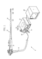
- an endoscope system 2 is composed of an endoscope 10, a processor device 11, a light source device 12, a monitor 29, and the like.
- the endoscope 10 is provided with an insert section 14 to be inserted into a body cavity of a patient, a handling section 15 connected to a basal (proximal) end portion of the insert section 14, and a universal cord 16 connected to the processor device 11 and the light source device 12.
- a connector 28 is connected to an end of the universal cord 16.
- the connector 28 is of a multi-connection type. The connector 28 is connected to each of the processor device 11 and the light source device 12.
- An air/water feeding device 13 is incorporated in the light source device 12.
- the air/water feeding device 13 is composed of a well-known air-supply pump 13A and a water tank 13B.
- the air-supply pump 13A generates pressure to feed gas such as air and liquid such as cleaning water.
- the water tank 13B holds the cleaning water and is provided externally to the light source device 12.
- the insert section 14 has a distal portion 14A, a bending portion 14B, and a flexible tube portion 14C.
- the distal portion 14A is provided with an imaging section for imaging the inside of the body cavity.
- the bending portion 14B is bendable.
- the flexible tube portion 14C has flexibility.
- a distal end side of the insert section 14 is simply referred to as “the distal end side”.
- a proximal end side of the insert section 14 is simply referred to as "the proximal end side”.
- An end cover 20 of the distal portion 14A is provided with a capture window 21, lighting windows 22A and 22B, a forceps outlet 23 from which forceps or the like are projected into the body cavity, and a jet nozzle 24.
- the imaging section is attached.
- the imaging section images the inside of the body cavity of the patient.
- the two lighting windows 22A and 22B are disposed symmetrically with respect to the capture window 21.
- the lighting windows 22A and 22B apply illumination light from the light source device 12 to a region of interest in the body cavity.
- the forceps outlet 23 is connected to a forceps inlet 26 provided to the handling section 15.
- a treatment tool such as forceps, an injection needle, or a high frequency surgical knife is inserted into the forceps inlet 26.
- the jet nozzle 24 ejects the air and the cleaning water, supplied from the air/water feeding device 13, to the capture window 21 to wash off dirt from the capture window 21 with the cleaning water and dry the capture window 21 with the air.
- the processor device 11 performs various image processes on an image signal, inputted from the imaging section through the universal cord 16 and the connector 28, to produce an endoscopic image.
- the endoscopic image is displayed on the monitor 29 through a cable.
- the processor device 11 is connected to the light source device 12 through a communication cable, and communicates various types of control data with the light source device 12.
- light guides 31A and 31B, a forceps channel 32, an air/water channel 33, and a multi-core cable 34 run through the flexible tube portion 14C.
- the light guides 31A and 31B deliver the light from the light source device 12 to the lighting windows 22A and 22B.
- the forceps channel 32 is a flexible metal pipe and connects the forceps inlet 26 and the forceps outlet 23.
- the air/water channel 33 feeds the air and the cleaning water from the air/water feeding device 13 to the jet nozzle 24.
- the multi-core cable 34 electrically connects the processor device 11 and the imaging section.
- the flexible tube portion 14C is composed of three layers, a helical tubular layer (flex) 36, a mesh tubular layer (blade) 37, and a resin (silicon rubber) layer 38 in this order from the inside.
- the helical tubular layer 36 is made from helically wound steel coils.
- the mesh tubular layer 37 covers the helical tubular layer 36 to prevent the helical tubular layer 36 from being stretched.
- the resin layer 38 has flexibility and covers the mesh tubular layer 37.
- a metal stationary tube 41 and the end cover 20 are provided inside the distal portion 14A.
- the stationary tube 41 has thermal conductivity and houses the forceps channel 32 and the imaging section.
- the end cover 20 fills gaps in an opening on the distal end side of the stationary tube 41.
- the stationary tube 41 and the end cover 20 are covered with the resin layer 38.
- the light guides 31A and 31B, the forceps channel 32, the air/water channel 33, and the multi-core cable 34 run inside the stationary tube 41.
- the forceps channel 32 is connected to the forceps outlet 23 provided through the end cover 20.
- lighting lenses (not shown) are disposed behind the respective lighting windows 22A and 22B. Exits of the light guides 31A and 31B face the respective lighting lenses.
- the air/water channel 33 is connected to the jet nozzle 24. An end of each of the forceps channel 32, the light guides 31A and 31B, and the air/water channel 33 is fixed to the end cover 20.
- the other end of the forceps channel 32 is connected to the forceps inlet 26, and the other ends of the light guides 31A and 31B are connected to the light source device 12, and the other end of the air/water channel 33 is connected to the air/water feeding device 13, through the bending portion 14B, the flexible tube portion 14C, the handling section 15, and the like.
- the multi-core cable 34 is composed of signal lines 34A, first shield members 34B that cover the respective signal lines 34A, and a second shield member 34C.
- the second shield member 34C covers and holds the signal lines 34A, each covered with the first shield member 34B, together.
- Each of the first shield member 34B and the second shield member 34C functions as an electric shield layer and an electromagnetic shield layer.
- the second shield member 34C is provided with an innermost layer 34C1, a middle layer 34C2, being an electrically conductive layer, and an outermost layer 34C3.
- Each of the innermost and outermost layers 34C1 and 34C3 is made from electrically insulating material.
- the middle layer 34C2 is made from electrically conductive material.
- the distal portion of the endoscope 10 incorporates the imaging section.
- the imaging section is provided with an objective optical system 51, a prism 52, and an image sensor 54.
- Image light of the region of interest captured through the capture window 21 is incident on the prism 52 through the objective optical system 51.
- the prism 52 refracts the image light from the objective optical system 51 in a substantially vertical direction, and thereby forms an image of the region of interest on an imaging surface of the image sensor 54.
- the image sensor 54 is a CCD image sensor, a CMOS image sensor, or the like, and generates an image signal into which an image is converted photoelectrically.
- the image signal is outputted through a circuit board 55 provided on the opposite side of the imaging surface that is parallel (or substantially parallel) with a direction of insertion of the insert section 14.
- the circuit board 55 is electrically connected to each of the signal lines 34A of the multi-core cable 34.
- the image signal is sent to the processor device 11 through the multi-core cable 34. It is preferable that the size of the circuit board 55 is greater than or equal to the size of the image sensor 54.
- Transparent glass 56 protects an imaging surface side of the image sensor 54.
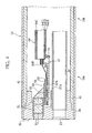
- a heat dissipation substrate (thermal conductive substrate) 57 is overlaid onto the back of the circuit board 55.
- the heat dissipation substrate 57 may be overlaid onto the back of the image sensor 54.
- the heat dissipation substrate 57 is provided with first and second high thermal conductive layers 57A and 57B so as to maintain electrical insulation with the circuit board 55 while having good thermal conductivity.
- the first high thermal conductive layer 57A is made from electrically insulating material with relatively high thermal conductivity.
- the second high thermal conductive layer 57B is made from material with thermal conductivity higher than that of the first high thermal conductive layer 57A.
- the first and second high thermal conductive layers 57A and 57B are adhered to each other using an adhesive with good thermal conductivity.
- the heat dissipation substrate 57 may be composed only of the first high thermal conductive layer 57A.
- the heat dissipation substrate 57 may be composed only of the second high thermal conductive layer 57B.
- the first high thermal conductive layer 57A is adhered to the circuit board 55 disposed on and parallel (or substantially parallel) with the opposite side of the imaging surface of the image sensor 54 (the back of the image sensor 54) with the use of an electrically insulating adhesive.
- the adhesive preferably has high thermal conductivity in view of heat dissipation performance. It is preferable that a distal end side of the heat dissipation substrate 57 is flush with or protrudes relative to the circuit board 55.
- the proximal end side of the heat dissipation substrate 57 preferably protrudes relative to the circuit board 55.
- the proximal end side of the second high thermal conductive layer 57B preferably protrudes relative to the first high thermal conductive layer 57A.
- a flexible heat dissipation substrate is used as the heat dissipation substrate 57.
- the flexible heat dissipation substrate is composed of a base layer and a metal layer formed on the base layer.
- the base layer is made from electrically insulating polymer with relatively high thermal conductivity, for example, polyimide.
- the metal layer is made from metal with high electrical conductivity.
- the base layer functions as the first high thermal conductive layer 57A.
- the metal layer functions as the second high thermal conductive layer 57B.
- the base layer is made from polyimide.
- the metal layer is made from copper.
- a known product such as DIA-FINE Japanese registered trademark No. 4901676
- Japanese registered trademark No. 4901676 Japanese registered trademark No. 4901676
- a ceramic heat dissipation substrate may be used as the heat dissipation substrate 57.
- the ceramic heat dissipation substrate is composed of a base layer and a metal layer formed on the base layer.
- the base layer is made from electrically insulating ceramic with relatively high thermal conductivity.
- the metal layer is made from metal such as copper or aluminum.
- the base layer functions as the first high thermal conductive layer 57A.
- the metal layer functions as the second high thermal conductive layer 57B.
- the base layer is made from alumina, aluminum nitride, or silicon nitride.
- the ceramic heat dissipation substrates include known products such as the above-mentioned ceramic metallized with the metal layer, DBC (direct-bond-copper, ceramic on which copper is bonded) (Japanese registered trademark No. 1877649 ), and DBA (direct-bond-aluminum, ceramic on which aluminum is bonded) (Japanese registered trademark No. 2011-082326 ).
- the insert section 14 of the endoscope 10 is inserted into the body cavity.
- the image sensor 54 is driven by a signal sent from the processor device 11 through the signal lines 34A.
- the signal lines 34A extend through the connector 28, the universal cord 16, the handling section 15, the flexible tube portion 14C, and the bending portion 14B to the image sensor 54.
- the image light of the region of interest is incident on the imaging surface of the image sensor 54 through the objective optical system 51 and the prism 52, and the image sensor 54 outputs the image signal.
- the image signal is transmitted to the processor device 11 in the reverse direction of the above-described transmission path of the signal from the processor device 11.
- the image sensor 54 generates heat during operation.
- the heat is transmitted to the second high thermal conductive layer 57B with high thermal conductivity, through the first high thermal conductive layer 57A with relatively high thermal conductivity.
- the heat is transmitted from the distal end side to the proximal end side of the second high thermal conductive layer 57B.
- the heat is then transmitted to the middle layer 34C2 of the second shield member 34C of the multi-core cable 34 through a connection member 72.
- the heat transmitted to the middle layer 34C2 is transmitted through the multi-core cable 34, in the same direction as the image signal outputted from the image sensor 54.
- the heat is released to the outside of the endoscope 10 through the universal cord 16.
- the distal end side of the heat dissipation substrate 57 is flush with or protrudes relative to the image sensor 54 or the circuit board 55. It is preferable that the proximal end side of the heat dissipation substrate 57 protrudes relative to the image sensor 54 or the circuit board 55. Thereby, the capacity of the heat dissipation substrate 57 to receive the heat from the image sensor 54 increases.
- the second high thermal conductive layer 57B is preferably made from metal with high heat capacity, for example, copper. Thereby, the second high thermal conductive layer 57B can receive most of the heat generated by the image sensor 54 and transmitted through the first high thermal conductive layer 57A.
- the arrangement of the first high thermal conductive layer 57A and the second high thermal conductive layer 57B can be reversed only when an electrically insulating adhesive is used.
- Like reference numerals designate like or corresponding parts in Figs. 4 and 5 , and descriptions thereof are omitted.
- the second high thermal conductive layer 57B made from the electrically conductive material is not electrically connected to the forceps channel 32 and the like because the first high thermal conductive layer 57A made from the electrically insulating material faces the forceps channel 32 and the like.
- the heat dissipation substrate 57 is provided to the image sensor 54 through the circuit board 55 in a manner similar to the first embodiment. Alternatively, the heat dissipation substrate 57 may be adhered directly to the opposite side of the imaging surface of the image sensor 54 (the back of the image sensor 54) only using the electrically insulating adhesive.
- connection member 72 thermally connects a proximal end portion of the second high thermal conductive layer 57B and a part of the middle layer 34C2 of the second shield member 34C. To improve the thermal conductivity, it is preferable that the connection member 72 has good electrical conductivity.
- the connection member 72 is formed using metal paste, such as silver paste, soldering, wire bonding, or tape bonding, for example. Note that, the proximal end side of the second high thermal conductive layer 57B preferably protrudes relative to the first high thermal conductive layer 57A. Thereby, the connection member 72 is formed easily.
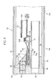
- a heat dissipation substrate 75 is disposed on the opposite side of the imaging surface of the image sensor 54 through the circuit board 55 such that a plane direction of the heat dissipation substrate 75 is parallel with (or substantially parallel with) the image sensor 54.
- the heat dissipation substrate 75 is provided with first to third high thermal conductive layers 75A, 75B, and 75C.
- the first high thermal conductive layer 75A is sandwiched by the second and third high thermal conductive layers 75B and 75C.
- the first high thermal conductive layer 75A is made from electrically insulating and thermally conductive material.
- Each of the second and third high thermal conductive layers 75B and 75C is made from material with good thermal conductivity.
- the first to third high thermal conductive layers 75A, 75B, and 75C are adhered together with an adhesive. Note that, like reference numerals designate like or corresponding parts in Figs. 4 and 6 , and descriptions thereof are omitted.
- the third high thermal conductive layer 75C is adhered to the circuit board 55 using an electrically insulating and thermally conductive adhesive, for example.
- electrically conductive material such as solder or paste containing metal particles is preferably used for bonding the metallized surface of the circuit board 55 and the third high thermal conductive layer 75C in view of adhesive strength and adhesive reliability. Thereby, the heat is transmitted without using the adhesive layer. This is preferable in view of thermal conductivity, and thus the third high thermal conductive layer 75C receives the heat more effectively.
- the distal end side of the heat dissipation substrate 75 is in flush with or protrudes relative to the circuit board 55. It is preferable that the proximal end side of the heat dissipation substrate 75 protrudes relative to the circuit board 55.
- the proximal end side of the second high thermal conductive layer 75B preferably protrudes relative to the first high thermal conductive layer 75A.
- the proximal end side of the third high thermal conductive layer 75C is preferably shorter than the first high thermal conductive layer 75A.
- a flexible heat dissipation substrate may be used as the heat dissipation substrate 75.
- the flexible heat dissipation substrate is provided with a base layer and two metal layers formed on respective surfaces of the base layer.
- the base layer and the two metal layers function as the first to third high thermal conductive layers 75A, 75B, and 75C, respectively.
- a ceramic heat dissipation substrate may be used as the heat dissipation substrate 75.
- the ceramic heat dissipation substrate is provided with a base layer and two metal layers formed on respective surfaces of the base layer.
- the base laser and the two metal layers function as the first to third high thermal conductive layers 75A, 75B, and 75C, respectively.
- connection member 72 thermally connects a proximal end portion of the second high thermal conductive layer 75B and a part of the middle layer 34C2 of the second shield member 34C.
- the proximal end side of the third high thermal conductive layer 75C is preferably shorter than the first high thermal conductive layer 75A. Thereby, the connection member 72 is formed more easily. In this case, it is necessary to prevent the third high thermal conductive layer 75C from being electrically connected to the second high thermal conductive layer 75B and the signal lines 34A.
- the third high thermal conductive layer 75C in addition to the first and second high thermal conductive layers 75A and 75B, receives the heat from the image sensor 54. Thereby, higher heat dissipation performance is achieved.
Landscapes
- Health & Medical Sciences (AREA)
- Life Sciences & Earth Sciences (AREA)
- Surgery (AREA)
- Biomedical Technology (AREA)
- Medical Informatics (AREA)
- Optics & Photonics (AREA)
- Pathology (AREA)
- Radiology & Medical Imaging (AREA)
- Biophysics (AREA)
- Engineering & Computer Science (AREA)
- Physics & Mathematics (AREA)
- Heart & Thoracic Surgery (AREA)
- Nuclear Medicine, Radiotherapy & Molecular Imaging (AREA)
- Molecular Biology (AREA)
- Animal Behavior & Ethology (AREA)
- General Health & Medical Sciences (AREA)
- Public Health (AREA)
- Veterinary Medicine (AREA)
- Endoscopes (AREA)
- Instruments For Viewing The Inside Of Hollow Bodies (AREA)
Applications Claiming Priority (1)
| Application Number | Priority Date | Filing Date | Title |
|---|---|---|---|
| JP2012069235A JP5540036B2 (ja) | 2012-03-26 | 2012-03-26 | 内視鏡 |
Publications (2)
| Publication Number | Publication Date |
|---|---|
| EP2644084A1 true EP2644084A1 (fr) | 2013-10-02 |
| EP2644084B1 EP2644084B1 (fr) | 2015-03-25 |
Family
ID=47750536
Family Applications (1)
| Application Number | Title | Priority Date | Filing Date |
|---|---|---|---|
| EP13156981.6A Active EP2644084B1 (fr) | 2012-03-26 | 2013-02-27 | Endoscope |
Country Status (4)
| Country | Link |
|---|---|
| US (1) | US20130253272A1 (fr) |
| EP (1) | EP2644084B1 (fr) |
| JP (1) | JP5540036B2 (fr) |
| CN (1) | CN203341708U (fr) |
Cited By (2)
| Publication number | Priority date | Publication date | Assignee | Title |
|---|---|---|---|---|
| CN109414253A (zh) * | 2016-06-30 | 2019-03-01 | 富士胶片株式会社 | 超声波内窥镜 |
| US10524649B2 (en) | 2014-05-26 | 2020-01-07 | Olympus Winter & Ibe Gmbh | Video endoscope |
Families Citing this family (34)
| Publication number | Priority date | Publication date | Assignee | Title |
|---|---|---|---|---|
| US9901244B2 (en) | 2009-06-18 | 2018-02-27 | Endochoice, Inc. | Circuit board assembly of a multiple viewing elements endoscope |
| US9872609B2 (en) | 2009-06-18 | 2018-01-23 | Endochoice Innovation Center Ltd. | Multi-camera endoscope |
| WO2012077116A1 (fr) | 2010-12-09 | 2012-06-14 | Peermedical Ltd. | Carte de circuit électronique flexible pour endoscope à caméras multiples |
| US11278190B2 (en) | 2009-06-18 | 2022-03-22 | Endochoice, Inc. | Multi-viewing element endoscope |
| US9492063B2 (en) | 2009-06-18 | 2016-11-15 | Endochoice Innovation Center Ltd. | Multi-viewing element endoscope |
| US8926502B2 (en) | 2011-03-07 | 2015-01-06 | Endochoice, Inc. | Multi camera endoscope having a side service channel |
| US11547275B2 (en) | 2009-06-18 | 2023-01-10 | Endochoice, Inc. | Compact multi-viewing element endoscope system |
| US9706903B2 (en) | 2009-06-18 | 2017-07-18 | Endochoice, Inc. | Multiple viewing elements endoscope system with modular imaging units |
| US9713417B2 (en) | 2009-06-18 | 2017-07-25 | Endochoice, Inc. | Image capture assembly for use in a multi-viewing elements endoscope |
| US9642513B2 (en) | 2009-06-18 | 2017-05-09 | Endochoice Inc. | Compact multi-viewing element endoscope system |
| EP2442706B1 (fr) | 2009-06-18 | 2014-11-12 | EndoChoice Innovation Center Ltd. | Endoscope à caméras multiples |
| US11864734B2 (en) | 2009-06-18 | 2024-01-09 | Endochoice, Inc. | Multi-camera endoscope |
| US9101268B2 (en) | 2009-06-18 | 2015-08-11 | Endochoice Innovation Center Ltd. | Multi-camera endoscope |
| US12137873B2 (en) | 2009-06-18 | 2024-11-12 | Endochoice, Inc. | Compact multi-viewing element endoscope system |
| US10165929B2 (en) | 2009-06-18 | 2019-01-01 | Endochoice, Inc. | Compact multi-viewing element endoscope system |
| US12220105B2 (en) | 2010-06-16 | 2025-02-11 | Endochoice, Inc. | Circuit board assembly of a multiple viewing elements endoscope |
| EP4233680B1 (fr) | 2010-09-20 | 2025-06-18 | EndoChoice, Inc. | Section distal d'endoscope comprenant un composant unique de canalisation de fluides |
| US9560953B2 (en) | 2010-09-20 | 2017-02-07 | Endochoice, Inc. | Operational interface in a multi-viewing element endoscope |
| EP2635932B1 (fr) | 2010-10-28 | 2019-06-05 | EndoChoice Innovation Center Ltd. | Systèmes optiques pour endoscopes à capteurs multiples |
| US12204087B2 (en) | 2010-10-28 | 2025-01-21 | Endochoice, Inc. | Optical systems for multi-sensor endoscopes |
| EP3420886B8 (fr) | 2010-12-09 | 2020-07-15 | EndoChoice, Inc. | Endoscope multicaméra à carte de circuit électronique souple |
| US11889986B2 (en) | 2010-12-09 | 2024-02-06 | Endochoice, Inc. | Flexible electronic circuit board for a multi-camera endoscope |
| CN103491854B (zh) | 2011-02-07 | 2016-08-24 | 恩多卓斯创新中心有限公司 | 用于多摄影机内窥镜的多元件罩 |
| CA2798716A1 (fr) | 2011-12-13 | 2013-06-13 | Endochoice Innovation Center Ltd. | Endoscope a pointe amovible |
| CA2798729A1 (fr) | 2011-12-13 | 2013-06-13 | Peermedical Ltd. | Connecteur rotatif pour un endoscope |
| US9560954B2 (en) | 2012-07-24 | 2017-02-07 | Endochoice, Inc. | Connector for use with endoscope |
| US9986899B2 (en) | 2013-03-28 | 2018-06-05 | Endochoice, Inc. | Manifold for a multiple viewing elements endoscope |
| US9993142B2 (en) | 2013-03-28 | 2018-06-12 | Endochoice, Inc. | Fluid distribution device for a multiple viewing elements endoscope |
| US10499794B2 (en) | 2013-05-09 | 2019-12-10 | Endochoice, Inc. | Operational interface in a multi-viewing element endoscope |
| EP3050491B1 (fr) * | 2013-09-26 | 2018-10-10 | Olympus Corporation | Dispositif d'endoscope |
| WO2018198247A1 (fr) * | 2017-04-26 | 2018-11-01 | オリンパス株式会社 | Endoscope, module de capture d'image et procédé de fabrication d'un module de capture d'image |
| JP7088789B2 (ja) * | 2018-08-31 | 2022-06-21 | 株式会社モリタ製作所 | 撮像装置 |
| CN110477843B (zh) * | 2019-09-17 | 2024-09-06 | 重庆金山医疗技术研究院有限公司 | 导光软管和内窥镜系统 |
| WO2021238239A1 (fr) * | 2020-05-25 | 2021-12-02 | 卓外(上海)医疗电子科技有限公司 | Structure de dissipation de chaleur de partie d'insertion d'endoscope |
Citations (9)
| Publication number | Priority date | Publication date | Assignee | Title |
|---|---|---|---|---|
| JP2009066118A (ja) | 2007-09-12 | 2009-04-02 | Olympus Corp | 内視鏡用冷却装置及び内視鏡装置 |
| JP2009296542A (ja) | 2008-06-09 | 2009-12-17 | Olympus Medical Systems Corp | 撮像装置 |
| US20100033559A1 (en) | 2008-08-05 | 2010-02-11 | Olympus Corporation | Image pick-up module for endoscope apparatus |
| WO2010064506A1 (fr) * | 2008-12-04 | 2010-06-10 | オリンパスメディカルシステムズ株式会社 | Dispositif d’imagerie et endoscope |
| JP2010201023A (ja) | 2009-03-04 | 2010-09-16 | Fujifilm Corp | 内視鏡 |
| JP2010279527A (ja) | 2009-06-04 | 2010-12-16 | Hoya Corp | 内視鏡 |
| JP2011082326A (ja) | 2009-10-07 | 2011-04-21 | Hitachi Kokusai Electric Inc | 半導体装置の製造方法及び基板の製造方法及び基板処理装置。 |
| JP2011200401A (ja) | 2010-03-25 | 2011-10-13 | Fujifilm Corp | 内視鏡 |
| JP4901676B2 (ja) | 2007-09-28 | 2012-03-21 | 株式会社東芝 | ナンバープレート情報処理装置及びナンバープレート情報処理方法 |
Family Cites Families (23)
| Publication number | Priority date | Publication date | Assignee | Title |
|---|---|---|---|---|
| DE2835331C3 (de) * | 1978-08-11 | 1981-11-05 | Siemens AG, 1000 Berlin und 8000 München | Endoskop mit elektrischer Bildübertragung |
| US4563383A (en) * | 1984-03-30 | 1986-01-07 | General Electric Company | Direct bond copper ceramic substrate for electronic applications |
| JPH0461293A (ja) * | 1990-06-29 | 1992-02-27 | Toshiba Corp | 回路基板及びその製造方法 |
| US5532512A (en) * | 1994-10-03 | 1996-07-02 | General Electric Company | Direct stacked and flip chip power semiconductor device structures |
| US5917157A (en) * | 1994-12-12 | 1999-06-29 | Remsburg; Ralph | Multilayer wiring board laminate with enhanced thermal dissipation to dielectric substrate laminate |
| US6033787A (en) * | 1996-08-22 | 2000-03-07 | Mitsubishi Materials Corporation | Ceramic circuit board with heat sink |
| TW411595B (en) * | 1999-03-20 | 2000-11-11 | Siliconware Precision Industries Co Ltd | Heat structure for semiconductor package device |
| US6194246B1 (en) * | 1999-08-25 | 2001-02-27 | Motorola Inc. | Process for fabricating electronic devices having a thermally conductive substrate |
| CA2400381A1 (fr) * | 2000-02-18 | 2001-08-23 | Richard M. Beane | Dispositifs et procedes de chauffage et de nettoyage de lentilles d'instruments chirurgicaux optiques |
| US20010038140A1 (en) * | 2000-04-06 | 2001-11-08 | Karker Jeffrey A. | High rigidity, multi-layered semiconductor package and method of making the same |
| JP4418202B2 (ja) * | 2003-10-06 | 2010-02-17 | オリンパス株式会社 | 内視鏡 |
| US20050137459A1 (en) * | 2003-12-17 | 2005-06-23 | Scimed Life Systems, Inc. | Medical device with OLED illumination light source |
| US7668450B2 (en) * | 2005-01-28 | 2010-02-23 | Stryker Corporation | Endoscope with integrated light source |
| EP1911389A4 (fr) * | 2005-08-05 | 2009-12-16 | Olympus Medical Systems Corp | Unité électroluminescente |
| US20080290378A1 (en) * | 2007-05-21 | 2008-11-27 | Myers Bruce A | Transistor package with wafer level dielectric isolation |
| JP2010022815A (ja) * | 2008-06-18 | 2010-02-04 | Olympus Corp | 内視鏡装置 |
| JP2010088661A (ja) * | 2008-10-08 | 2010-04-22 | Olympus Corp | 内視鏡 |
| WO2010132517A2 (fr) * | 2009-05-12 | 2010-11-18 | David Gershaw | Rattrapage par del pour ampoules miniatures |
| JP2010263946A (ja) * | 2009-05-12 | 2010-11-25 | Fujifilm Corp | 内視鏡 |
| JP5519211B2 (ja) * | 2009-08-10 | 2014-06-11 | オリンパス株式会社 | 内視鏡装置 |
| DE102009049683B4 (de) * | 2009-10-19 | 2016-06-09 | Richard Wolf Gmbh | Endoskopisches Instrument |
| JP2012050756A (ja) * | 2010-09-02 | 2012-03-15 | Fujifilm Corp | 内視鏡装置及びその撮像素子放熱方法 |
| JP2012055489A (ja) * | 2010-09-08 | 2012-03-22 | Fujifilm Corp | 電子内視鏡用の撮像装置及び撮像装置の製造方法 |
-
2012
- 2012-03-26 JP JP2012069235A patent/JP5540036B2/ja not_active Expired - Fee Related
-
2013
- 2013-02-27 EP EP13156981.6A patent/EP2644084B1/fr active Active
- 2013-02-27 CN CN201320088999.0U patent/CN203341708U/zh not_active Expired - Lifetime
- 2013-02-28 US US13/781,076 patent/US20130253272A1/en not_active Abandoned
Patent Citations (10)
| Publication number | Priority date | Publication date | Assignee | Title |
|---|---|---|---|---|
| JP2009066118A (ja) | 2007-09-12 | 2009-04-02 | Olympus Corp | 内視鏡用冷却装置及び内視鏡装置 |
| JP4901676B2 (ja) | 2007-09-28 | 2012-03-21 | 株式会社東芝 | ナンバープレート情報処理装置及びナンバープレート情報処理方法 |
| JP2009296542A (ja) | 2008-06-09 | 2009-12-17 | Olympus Medical Systems Corp | 撮像装置 |
| US20100033559A1 (en) | 2008-08-05 | 2010-02-11 | Olympus Corporation | Image pick-up module for endoscope apparatus |
| JP2010035815A (ja) | 2008-08-05 | 2010-02-18 | Olympus Corp | 内視鏡装置の撮像モジュール |
| WO2010064506A1 (fr) * | 2008-12-04 | 2010-06-10 | オリンパスメディカルシステムズ株式会社 | Dispositif d’imagerie et endoscope |
| JP2010201023A (ja) | 2009-03-04 | 2010-09-16 | Fujifilm Corp | 内視鏡 |
| JP2010279527A (ja) | 2009-06-04 | 2010-12-16 | Hoya Corp | 内視鏡 |
| JP2011082326A (ja) | 2009-10-07 | 2011-04-21 | Hitachi Kokusai Electric Inc | 半導体装置の製造方法及び基板の製造方法及び基板処理装置。 |
| JP2011200401A (ja) | 2010-03-25 | 2011-10-13 | Fujifilm Corp | 内視鏡 |
Cited By (3)
| Publication number | Priority date | Publication date | Assignee | Title |
|---|---|---|---|---|
| US10524649B2 (en) | 2014-05-26 | 2020-01-07 | Olympus Winter & Ibe Gmbh | Video endoscope |
| CN109414253A (zh) * | 2016-06-30 | 2019-03-01 | 富士胶片株式会社 | 超声波内窥镜 |
| US11076828B2 (en) | 2016-06-30 | 2021-08-03 | Fujifilm Corporation | Ultrasonic endoscope |
Also Published As
| Publication number | Publication date |
|---|---|
| JP2013198642A (ja) | 2013-10-03 |
| JP5540036B2 (ja) | 2014-07-02 |
| CN203341708U (zh) | 2013-12-18 |
| US20130253272A1 (en) | 2013-09-26 |
| EP2644084B1 (fr) | 2015-03-25 |
Similar Documents
| Publication | Publication Date | Title |
|---|---|---|
| EP2644084B1 (fr) | Endoscope | |
| JP5945653B1 (ja) | 固体撮像装置およびこの固体撮像装置を備えた電子内視鏡 | |
| JP5436470B2 (ja) | 撮像装置及びこれを備えた電子内視鏡 | |
| US8876702B2 (en) | Electronic endoscope in which static-protective member is provided in distal end portion of insertion portion | |
| JP6654699B2 (ja) | 超音波内視鏡 | |
| EP3479769B1 (fr) | Endoscope à ultrasons et son procédé de fabrication | |
| US10098522B2 (en) | Endoscope | |
| US20210068623A1 (en) | Imaging unit and oblique-viewing endoscope | |
| JP2011200399A (ja) | 内視鏡 | |
| JP2015198739A (ja) | 内視鏡用曇り防止ユニット及び内視鏡システム | |
| US10661310B2 (en) | Ultrasonic oscillator unit | |
| US20180310813A1 (en) | Imageing unit and endoscope | |
| US20140148704A1 (en) | Endoscope apparatus | |
| JP7585104B2 (ja) | 撮像モジュール | |
| WO2024214613A1 (fr) | Dispositif d'imagerie endoscopique, endoscope et endoscope à ultrasons | |
| JP2011200338A (ja) | 電子内視鏡 | |
| US10080480B2 (en) | Endoscope | |
| JP7385736B2 (ja) | 内視鏡撮像装置 | |
| JP7676171B2 (ja) | 撮像モジュール | |
| CN115220214A (zh) | 内窥镜摄像机头 | |
| JPWO2016203535A1 (ja) | 内視鏡 |
Legal Events
| Date | Code | Title | Description |
|---|---|---|---|
| PUAI | Public reference made under article 153(3) epc to a published international application that has entered the european phase |
Free format text: ORIGINAL CODE: 0009012 |
|
| AK | Designated contracting states |
Kind code of ref document: A1 Designated state(s): AL AT BE BG CH CY CZ DE DK EE ES FI FR GB GR HR HU IE IS IT LI LT LU LV MC MK MT NL NO PL PT RO RS SE SI SK SM TR |
|
| AX | Request for extension of the european patent |
Extension state: BA ME |
|
| 17P | Request for examination filed |
Effective date: 20131001 |
|
| RBV | Designated contracting states (corrected) |
Designated state(s): AL AT BE BG CH CY CZ DE DK EE ES FI FR GB GR HR HU IE IS IT LI LT LU LV MC MK MT NL NO PL PT RO RS SE SI SK SM TR |
|
| GRAP | Despatch of communication of intention to grant a patent |
Free format text: ORIGINAL CODE: EPIDOSNIGR1 |
|
| INTG | Intention to grant announced |
Effective date: 20140917 |
|
| GRAS | Grant fee paid |
Free format text: ORIGINAL CODE: EPIDOSNIGR3 |
|
| GRAA | (expected) grant |
Free format text: ORIGINAL CODE: 0009210 |
|
| AK | Designated contracting states |
Kind code of ref document: B1 Designated state(s): AL AT BE BG CH CY CZ DE DK EE ES FI FR GB GR HR HU IE IS IT LI LT LU LV MC MK MT NL NO PL PT RO RS SE SI SK SM TR |
|
| REG | Reference to a national code |
Ref country code: GB Ref legal event code: FG4D |
|
| REG | Reference to a national code |
Ref country code: CH Ref legal event code: EP |
|
| REG | Reference to a national code |
Ref country code: IE Ref legal event code: FG4D |
|
| REG | Reference to a national code |
Ref country code: DE Ref legal event code: R096 Ref document number: 602013001281 Country of ref document: DE Effective date: 20150507 |
|
| REG | Reference to a national code |
Ref country code: AT Ref legal event code: REF Ref document number: 717347 Country of ref document: AT Kind code of ref document: T Effective date: 20150515 |
|
| PG25 | Lapsed in a contracting state [announced via postgrant information from national office to epo] |
Ref country code: LT Free format text: LAPSE BECAUSE OF FAILURE TO SUBMIT A TRANSLATION OF THE DESCRIPTION OR TO PAY THE FEE WITHIN THE PRESCRIBED TIME-LIMIT Effective date: 20150325 Ref country code: HR Free format text: LAPSE BECAUSE OF FAILURE TO SUBMIT A TRANSLATION OF THE DESCRIPTION OR TO PAY THE FEE WITHIN THE PRESCRIBED TIME-LIMIT Effective date: 20150325 Ref country code: SE Free format text: LAPSE BECAUSE OF FAILURE TO SUBMIT A TRANSLATION OF THE DESCRIPTION OR TO PAY THE FEE WITHIN THE PRESCRIBED TIME-LIMIT Effective date: 20150325 Ref country code: FI Free format text: LAPSE BECAUSE OF FAILURE TO SUBMIT A TRANSLATION OF THE DESCRIPTION OR TO PAY THE FEE WITHIN THE PRESCRIBED TIME-LIMIT Effective date: 20150325 |
|
| REG | Reference to a national code |
Ref country code: AT Ref legal event code: MK05 Ref document number: 717347 Country of ref document: AT Kind code of ref document: T Effective date: 20150325 |
|
| REG | Reference to a national code |
Ref country code: LT Ref legal event code: MG4D |
|
| PG25 | Lapsed in a contracting state [announced via postgrant information from national office to epo] |
Ref country code: RS Free format text: LAPSE BECAUSE OF FAILURE TO SUBMIT A TRANSLATION OF THE DESCRIPTION OR TO PAY THE FEE WITHIN THE PRESCRIBED TIME-LIMIT Effective date: 20150325 Ref country code: GR Free format text: LAPSE BECAUSE OF FAILURE TO SUBMIT A TRANSLATION OF THE DESCRIPTION OR TO PAY THE FEE WITHIN THE PRESCRIBED TIME-LIMIT Effective date: 20150626 Ref country code: LV Free format text: LAPSE BECAUSE OF FAILURE TO SUBMIT A TRANSLATION OF THE DESCRIPTION OR TO PAY THE FEE WITHIN THE PRESCRIBED TIME-LIMIT Effective date: 20150325 |
|
| PG25 | Lapsed in a contracting state [announced via postgrant information from national office to epo] |
Ref country code: NL Free format text: LAPSE BECAUSE OF FAILURE TO SUBMIT A TRANSLATION OF THE DESCRIPTION OR TO PAY THE FEE WITHIN THE PRESCRIBED TIME-LIMIT Effective date: 20150325 |
|
| PG25 | Lapsed in a contracting state [announced via postgrant information from national office to epo] |
Ref country code: EE Free format text: LAPSE BECAUSE OF FAILURE TO SUBMIT A TRANSLATION OF THE DESCRIPTION OR TO PAY THE FEE WITHIN THE PRESCRIBED TIME-LIMIT Effective date: 20150325 Ref country code: PT Free format text: LAPSE BECAUSE OF FAILURE TO SUBMIT A TRANSLATION OF THE DESCRIPTION OR TO PAY THE FEE WITHIN THE PRESCRIBED TIME-LIMIT Effective date: 20150727 Ref country code: ES Free format text: LAPSE BECAUSE OF FAILURE TO SUBMIT A TRANSLATION OF THE DESCRIPTION OR TO PAY THE FEE WITHIN THE PRESCRIBED TIME-LIMIT Effective date: 20150325 Ref country code: SK Free format text: LAPSE BECAUSE OF FAILURE TO SUBMIT A TRANSLATION OF THE DESCRIPTION OR TO PAY THE FEE WITHIN THE PRESCRIBED TIME-LIMIT Effective date: 20150325 Ref country code: RO Free format text: LAPSE BECAUSE OF FAILURE TO SUBMIT A TRANSLATION OF THE DESCRIPTION OR TO PAY THE FEE WITHIN THE PRESCRIBED TIME-LIMIT Effective date: 20150325 Ref country code: CZ Free format text: LAPSE BECAUSE OF FAILURE TO SUBMIT A TRANSLATION OF THE DESCRIPTION OR TO PAY THE FEE WITHIN THE PRESCRIBED TIME-LIMIT Effective date: 20150325 |
|
| PG25 | Lapsed in a contracting state [announced via postgrant information from national office to epo] |
Ref country code: PL Free format text: LAPSE BECAUSE OF FAILURE TO SUBMIT A TRANSLATION OF THE DESCRIPTION OR TO PAY THE FEE WITHIN THE PRESCRIBED TIME-LIMIT Effective date: 20150325 Ref country code: AT Free format text: LAPSE BECAUSE OF FAILURE TO SUBMIT A TRANSLATION OF THE DESCRIPTION OR TO PAY THE FEE WITHIN THE PRESCRIBED TIME-LIMIT Effective date: 20150325 Ref country code: IS Free format text: LAPSE BECAUSE OF FAILURE TO SUBMIT A TRANSLATION OF THE DESCRIPTION OR TO PAY THE FEE WITHIN THE PRESCRIBED TIME-LIMIT Effective date: 20150725 |
|
| REG | Reference to a national code |
Ref country code: DE Ref legal event code: R097 Ref document number: 602013001281 Country of ref document: DE |
|
| REG | Reference to a national code |
Ref country code: FR Ref legal event code: PLFP Year of fee payment: 4 |
|
| PG25 | Lapsed in a contracting state [announced via postgrant information from national office to epo] |
Ref country code: DK Free format text: LAPSE BECAUSE OF FAILURE TO SUBMIT A TRANSLATION OF THE DESCRIPTION OR TO PAY THE FEE WITHIN THE PRESCRIBED TIME-LIMIT Effective date: 20150325 |
|
| PLBE | No opposition filed within time limit |
Free format text: ORIGINAL CODE: 0009261 |
|
| STAA | Information on the status of an ep patent application or granted ep patent |
Free format text: STATUS: NO OPPOSITION FILED WITHIN TIME LIMIT |
|
| 26N | No opposition filed |
Effective date: 20160105 |
|
| PG25 | Lapsed in a contracting state [announced via postgrant information from national office to epo] |
Ref country code: IT Free format text: LAPSE BECAUSE OF FAILURE TO SUBMIT A TRANSLATION OF THE DESCRIPTION OR TO PAY THE FEE WITHIN THE PRESCRIBED TIME-LIMIT Effective date: 20150325 |
|
| PG25 | Lapsed in a contracting state [announced via postgrant information from national office to epo] |
Ref country code: SI Free format text: LAPSE BECAUSE OF FAILURE TO SUBMIT A TRANSLATION OF THE DESCRIPTION OR TO PAY THE FEE WITHIN THE PRESCRIBED TIME-LIMIT Effective date: 20150325 Ref country code: BE Free format text: LAPSE BECAUSE OF NON-PAYMENT OF DUE FEES Effective date: 20160229 |
|
| PG25 | Lapsed in a contracting state [announced via postgrant information from national office to epo] |
Ref country code: BE Free format text: LAPSE BECAUSE OF FAILURE TO SUBMIT A TRANSLATION OF THE DESCRIPTION OR TO PAY THE FEE WITHIN THE PRESCRIBED TIME-LIMIT Effective date: 20150325 |
|
| PG25 | Lapsed in a contracting state [announced via postgrant information from national office to epo] |
Ref country code: MC Free format text: LAPSE BECAUSE OF FAILURE TO SUBMIT A TRANSLATION OF THE DESCRIPTION OR TO PAY THE FEE WITHIN THE PRESCRIBED TIME-LIMIT Effective date: 20150325 Ref country code: LU Free format text: LAPSE BECAUSE OF FAILURE TO SUBMIT A TRANSLATION OF THE DESCRIPTION OR TO PAY THE FEE WITHIN THE PRESCRIBED TIME-LIMIT Effective date: 20160227 |
|
| REG | Reference to a national code |
Ref country code: CH Ref legal event code: PL |
|
| PG25 | Lapsed in a contracting state [announced via postgrant information from national office to epo] |
Ref country code: LI Free format text: LAPSE BECAUSE OF NON-PAYMENT OF DUE FEES Effective date: 20160229 Ref country code: CH Free format text: LAPSE BECAUSE OF NON-PAYMENT OF DUE FEES Effective date: 20160229 |
|
| REG | Reference to a national code |
Ref country code: IE Ref legal event code: MM4A |
|
| REG | Reference to a national code |
Ref country code: FR Ref legal event code: PLFP Year of fee payment: 5 |
|
| PG25 | Lapsed in a contracting state [announced via postgrant information from national office to epo] |
Ref country code: IE Free format text: LAPSE BECAUSE OF NON-PAYMENT OF DUE FEES Effective date: 20160227 |
|
| REG | Reference to a national code |
Ref country code: DE Ref legal event code: R082 Ref document number: 602013001281 Country of ref document: DE Representative=s name: KLUNKER IP PATENTANWAELTE PARTG MBB, DE |
|
| PG25 | Lapsed in a contracting state [announced via postgrant information from national office to epo] |
Ref country code: MT Free format text: LAPSE BECAUSE OF FAILURE TO SUBMIT A TRANSLATION OF THE DESCRIPTION OR TO PAY THE FEE WITHIN THE PRESCRIBED TIME-LIMIT Effective date: 20150325 |
|
| REG | Reference to a national code |
Ref country code: FR Ref legal event code: PLFP Year of fee payment: 6 |
|
| PG25 | Lapsed in a contracting state [announced via postgrant information from national office to epo] |
Ref country code: SM Free format text: LAPSE BECAUSE OF FAILURE TO SUBMIT A TRANSLATION OF THE DESCRIPTION OR TO PAY THE FEE WITHIN THE PRESCRIBED TIME-LIMIT Effective date: 20150325 Ref country code: HU Free format text: LAPSE BECAUSE OF FAILURE TO SUBMIT A TRANSLATION OF THE DESCRIPTION OR TO PAY THE FEE WITHIN THE PRESCRIBED TIME-LIMIT; INVALID AB INITIO Effective date: 20130227 Ref country code: CY Free format text: LAPSE BECAUSE OF FAILURE TO SUBMIT A TRANSLATION OF THE DESCRIPTION OR TO PAY THE FEE WITHIN THE PRESCRIBED TIME-LIMIT Effective date: 20150325 |
|
| PG25 | Lapsed in a contracting state [announced via postgrant information from national office to epo] |
Ref country code: MK Free format text: LAPSE BECAUSE OF FAILURE TO SUBMIT A TRANSLATION OF THE DESCRIPTION OR TO PAY THE FEE WITHIN THE PRESCRIBED TIME-LIMIT Effective date: 20150325 Ref country code: NO Free format text: LAPSE BECAUSE OF NON-PAYMENT OF DUE FEES Effective date: 20150625 Ref country code: MT Free format text: LAPSE BECAUSE OF FAILURE TO SUBMIT A TRANSLATION OF THE DESCRIPTION OR TO PAY THE FEE WITHIN THE PRESCRIBED TIME-LIMIT Effective date: 20160229 Ref country code: TR Free format text: LAPSE BECAUSE OF FAILURE TO SUBMIT A TRANSLATION OF THE DESCRIPTION OR TO PAY THE FEE WITHIN THE PRESCRIBED TIME-LIMIT Effective date: 20150325 |
|
| PG25 | Lapsed in a contracting state [announced via postgrant information from national office to epo] |
Ref country code: BG Free format text: LAPSE BECAUSE OF FAILURE TO SUBMIT A TRANSLATION OF THE DESCRIPTION OR TO PAY THE FEE WITHIN THE PRESCRIBED TIME-LIMIT Effective date: 20150325 |
|
| PG25 | Lapsed in a contracting state [announced via postgrant information from national office to epo] |
Ref country code: AL Free format text: LAPSE BECAUSE OF FAILURE TO SUBMIT A TRANSLATION OF THE DESCRIPTION OR TO PAY THE FEE WITHIN THE PRESCRIBED TIME-LIMIT Effective date: 20150325 |
|
| PGFP | Annual fee paid to national office [announced via postgrant information from national office to epo] |
Ref country code: GB Payment date: 20200219 Year of fee payment: 8 |
|
| PGFP | Annual fee paid to national office [announced via postgrant information from national office to epo] |
Ref country code: FR Payment date: 20200113 Year of fee payment: 8 |
|
| GBPC | Gb: european patent ceased through non-payment of renewal fee |
Effective date: 20210227 |
|
| PG25 | Lapsed in a contracting state [announced via postgrant information from national office to epo] |
Ref country code: GB Free format text: LAPSE BECAUSE OF NON-PAYMENT OF DUE FEES Effective date: 20210227 Ref country code: FR Free format text: LAPSE BECAUSE OF NON-PAYMENT OF DUE FEES Effective date: 20210228 |
|
| P01 | Opt-out of the competence of the unified patent court (upc) registered |
Effective date: 20230515 |
|
| PGFP | Annual fee paid to national office [announced via postgrant information from national office to epo] |
Ref country code: DE Payment date: 20260102 Year of fee payment: 14 |