WO2024224663A1 - 植物総体の栽培装置および栽培方法 - Google Patents
植物総体の栽培装置および栽培方法 Download PDFInfo
- Publication number
- WO2024224663A1 WO2024224663A1 PCT/JP2023/038947 JP2023038947W WO2024224663A1 WO 2024224663 A1 WO2024224663 A1 WO 2024224663A1 JP 2023038947 W JP2023038947 W JP 2023038947W WO 2024224663 A1 WO2024224663 A1 WO 2024224663A1
- Authority
- WO
- WIPO (PCT)
- Prior art keywords
- light
- shielding housing
- cultivation
- plant
- roots
- Prior art date
- Legal status (The legal status is an assumption and is not a legal conclusion. Google has not performed a legal analysis and makes no representation as to the accuracy of the status listed.)
- Ceased
Links
Images


Classifications
-
- Y—GENERAL TAGGING OF NEW TECHNOLOGICAL DEVELOPMENTS; GENERAL TAGGING OF CROSS-SECTIONAL TECHNOLOGIES SPANNING OVER SEVERAL SECTIONS OF THE IPC; TECHNICAL SUBJECTS COVERED BY FORMER USPC CROSS-REFERENCE ART COLLECTIONS [XRACs] AND DIGESTS
- Y02—TECHNOLOGIES OR APPLICATIONS FOR MITIGATION OR ADAPTATION AGAINST CLIMATE CHANGE
- Y02P—CLIMATE CHANGE MITIGATION TECHNOLOGIES IN THE PRODUCTION OR PROCESSING OF GOODS
- Y02P60/00—Technologies relating to agriculture, livestock or agroalimentary industries
- Y02P60/20—Reduction of greenhouse gas [GHG] emissions in agriculture, e.g. CO2
- Y02P60/21—Dinitrogen oxide [N2O], e.g. using aquaponics, hydroponics or efficiency measures
Definitions
- the present invention relates to a cultivation device that can be used to cultivate entire plants and a cultivation method using the same.
- a plant is composed of (1) the plant body present above ground in soil cultivation, such as trunks, stems, branches, and leaves, (2) the root system present underground in soil cultivation, (3) flowers, fruits, and other products, (4) seeds, (5) aromas, and (6) medicinal ingredients, and the whole is referred to as the "whole plant.”
- “underground stems” are excluded from (1) the stems constituting the plant body, and “underground stems” are included in (2) the root system.
- the “stem” is the organ that, in vascular plants, serves as the axis of the plant body, supports the leaves and fruits, and sends water and nutrients from the roots to the leaves and fruits, and sends nutrients produced in the leaves to the roots.
- Examples of edible or medicinal plants that store nutrients in their roots include sweet potato, yam, radish, carrot, turnip, burdock, and medicinal ginseng.
- rhizomes are one of the transformations of stems that occur underground in soil cultivation, and like roots, they function to support the entire plant, and some plants also have the function of storing nutrients.
- Examples of edible or medicinal plants that store nutrients in their rhizomes include potatoes, Jerusalem artichokes, konjac, taro, arrowheads, onions, ginger, and lily of the valley.
- the root system of a plant is known to have the roles of supporting the plant itself, absorbing nutrients and water necessary for the growth of the plant as a whole, and synthesizing and storing carbohydrates such as starch produced by photosynthesis in the above-ground parts, plant growth regulators, and various medicinal ingredients.
- mature, thick roots are known to mainly play a supporting role, while young roots and root hairs are known to efficiently absorb water and nutrients from the soil by increasing their surface area.
- a lack of oxygen can cause root rot and the entire plant to wither.
- the role of the root system cannot be confirmed directly with the naked eye because it is hidden in the soil, and even if the soil grains are removed, the distribution of various root types in the soil cannot be determined. Furthermore, even if the root system can be observed with the naked eye in hydroponic cultivation, the entire root system is submerged in flowing water, so it is not possible to distinguish between the parts that absorb water and the parts that absorb oxygen, and the reality is that no detailed investigation has been conducted at present.
- roots having a role mainly to absorb water and nutrients are referred to as "liquid-phase roots”
- roots having a role mainly to absorb oxygen are referred to as "air-phase roots”.
- the soil particles In conventional soil cultivation, it is ideal for the soil particles to form an aggregate structure.
- the entire root system absorbs water and nutrients from the water absorbed by the soil particles or aggregates and the liquid phase present in the gaps, and when the soil has a low water content, some of the roots come into contact with the surface of the soil particles as in ceramic cultivation and absorb water and nutrients as liquid phase roots, and in the gaps between the soil particles or aggregates they absorb oxygen from the air as air phase roots.
- air phase roots and liquid phase roots exist in a disorderly manner in the root system of plants cultivated in soil.
- the inventors thought that if the areas in the root system where liquid phase roots develop and the areas where air phase roots develop could be separated, and if the liquid phase roots could be made to absorb water and nutrients from the liquid phase and the air phase roots could absorb oxygen in the air from the air phase, then even if there was a shortage of dissolved oxygen in the liquid phase, the presence of the air phase roots would prevent oxygen deficiency in the root system of the entire plant. Therefore, the inventors aimed to provide an apparatus for cultivating a whole plant that can generate separate liquid-phase roots and air-phase roots in the root system without using soil, and a method for cultivating such a whole plant.
- “cultivation of the whole plant” includes industrially growing plants in order to utilize the whole plant for purposes such as fragrance, oxygen release and CO2 absorption, and moderation of humidity and temperature in the surrounding environment.
- a light-shielding housing having at least one through hole on a ceiling surface and storing a cultivation liquid; and an inner surface body exhibiting capillary force, the inner surface body being disposed on at least a part of the inner surface of the light-shielding housing. That is, the cultivation liquid is stored as stagnant water in a light-tight housing having an inner surface that exhibits capillary force. In the inner space of the light-tight housing, a large amount of root systems grow without contacting the inner surface, and tubers, root vegetables, etc. are accumulated.
- the capillary force refers to the ability to carry water upward against gravity, that is, the ability to suck water by capillary action.
- the capillary force is affected by the microstructure inside the inner body that exhibits the capillary force and the wettability of the material of the inner body with water.
- a light-tight housing is used with an inner surface having an inner body exhibiting capillary force installed on the inner surface, and water is supplied to the entire plant using stagnant water, which is the cultivation liquid inside the light-tight housing, and the capillary water of the inner surface is used to control the humidity and temperature in the internal space of the light-tight housing.
- stagnant water which is the cultivation liquid inside the light-tight housing
- the capillary water of the inner surface is used to control the humidity and temperature in the internal space of the light-tight housing.
- the cultivation device of the present invention has through holes as a means for supporting the entire plant, the supporting roots required for soil cultivation are not essential, and the total number of liquid phase roots and air phase roots is greatly increased.
- the whole plant cultivation device can be applied to various primordia without being limited to the type or size of the plant or the morphology of the plant.
- the morphology of the plant includes morphologies with roots and all morphologies of plants that do not have roots but can be regenerated (e.g., plant tissues or plant cells such as seeds, bulbs, rhizomes, above-ground stems, buds, adventitious buds, axillary buds, anthers, filaments, panicles, leaves, cuttings, seedlings, seedlings, scales, ovaries, ovules, embryos, pollen, adventitious embryos, adventitious roots, cultured plant bodies, etc.).
- a plant cultivation device comprising: A light-shielding housing having at least one through hole on a ceiling surface and storing a cultivation liquid; and an inner surface body exhibiting capillary force, the inner surface body being disposed on at least a part of the inner surface of the light-shielding housing.
- the light-shielding housing may be connected to a water level adjustment means for adjusting the water level of the cultivation liquid.
- the light-shielding housing may be composed of a box-shaped light-shielding housing body and a removable lid that covers the upper opening of the light-shielding housing body.
- the lid may be hung from multiple hanging fixtures that are hung across opposing opening edges of the light-shielding housing body.
- the through hole may be a long hole having a slit shape.
- At least one of the sides of the light-shielding housing may be provided with an openable and closable door.
- An inner body may be installed on the entire inner surface of the light-shielding housing.
- An inner surface body may be installed on the inner surface of the cover of the light-shielding housing, excluding the through-hole.
- An inner surface having water-retaining capacity capable of supplying the entire plant with cultivation liquid may be laid over the entire bottom surface of the light-shielding enclosure.
- the inner body may be removably attached to the light-shielding housing via at least one holder attached to at least the inner surface of the light-shielding housing.
- the inner body may be placed at an angle against the inside surface of the light-shielding housing.
- a platform on which the entire plant is placed may be provided on the bottom surface of the light-shielding housing.
- the mounting table may be formed from the same material as the inner body.
- the mounting table may be made of a wooden slatted floor.
- the inner surface body is a sintered product of a non-metallic inorganic solid material, contains interconnected pores that are voids, has a porosity of 10-80% (vol/vol) relative to the entire sintered product, has an average pore size of 3 ⁇ m or less, and preferably has pores with a pore size of 3 ⁇ m or less that account for 70% or more of the total voids by volume.
- An illuminated housing equipped with a light source that irradiates light toward the top surface of the light-shielding housing may be stacked on top of the light-shielding housing.
- An illumination unit equipped with a light source that irradiates light toward the upper surface of the light-shielding housing may be disposed above the light-shielding housing.
- a method for cultivating a whole plant includes the steps of: A method for cultivating a whole plant using the above-mentioned cultivation device for a whole plant, the method comprising the steps of: providing an inner surface body exhibiting capillary force on at least a part of an inner surface of a light-shielding housing that stores a cultivation liquid, and forming a spatial area capable of containing a root system of the whole plant within the light-shielding housing; A step of supplying a cultivation liquid to the light-shielding housing before or after the step of forming the spatial region;
- the present invention provides a method for cultivating a whole plant, comprising the steps of: growing roots in a cultivation liquid stored in a light-shielding housing, the roots absorbing moisture and nutrients from a liquid phase; and growing roots in moisture and oxygen present inside a spatial region of the light-shielding housing, the roots absorbing oxygen from a gas phase.
- the entire plant may be placed and grown on a platform installed on the bottom of the light-shielding enclosure.
- the cultivation liquid stored in the light-shielding enclosure is water or a nutrient solution containing the nutrients required for the overall growth of the plant being cultivated, and may be stagnant water.
- the nutrients are characterized by being essential macroelements selected from nitrogen, phosphorus, potassium, calcium, magnesium, and sulfur, essential trace elements selected from iron, manganese, boron, zinc, molybdenum, copper, chlorine, and nickel, or useful elements selected from silicon, sodium, cobalt, etc.
- soil is not required for growing the entire plant, so there is no need for vast areas of land, large facilities and equipment, and the energy required to operate the large facilities and equipment, and anyone can operate a plant factory cheaply anywhere.
- Soil cultivation not only ties the crops to a specific location, but also requires work to remove the soil from the root system after harvest, making it time-consuming to ship the crops.
- the plant is no longer restricted by soil or influenced by impurities from the soil, it will be possible to stimulate the development of technology to produce the entire plant industrially and utilize its chemical synthesis power to harvest the desired substance.
- the soil-free plant cultivation technology of this invention is the gateway to and fundamental technology for ultimate green chemistry.
- FIG. 1 is an overall perspective view of a first embodiment of a plant cultivation device according to the present invention
- FIG. 2 is an enlarged perspective view of a part of the cultivation apparatus shown in FIG. 1
- FIG. 2 is an enlarged perspective view of a part in section showing the cultivation apparatus shown in FIG. 1 in use
- FIG. 2 is a vertical cross-sectional view showing the cultivation apparatus shown in FIG. 1 in use
- FIG. 4 is a vertical cross-sectional view showing a second embodiment of the plant cultivation device according to the present invention.
- FIG. 11 is a perspective view showing a third embodiment of the plant cultivation device according to the present invention.
- FIG. 7 is a longitudinal sectional view of the cultivation apparatus shown in FIG. 6 as seen from the front.
- FIG. 7 is a longitudinal sectional view of the cultivation apparatus shown in FIG. 6 as seen from the front.
- FIG. 7 is a vertical cross-sectional view of the cultivation apparatus shown in FIG. 6 as seen from the left side.
- FIG. 11 is a perspective view showing a fourth embodiment of the plant cultivation device according to the present invention.
- FIG. 10 is a cross-sectional perspective view of the cultivation device shown in FIG.
- FIG. 13 is a vertical cross-sectional view of a fifth embodiment of the plant cultivation device according to the present invention.
- 1 is a photograph showing a first embodiment of a cultivation device according to the present invention.
- FIG. 2 is a plan view showing the results of measuring the photon flux density irradiated from a light source in Example 1.
- 4 is a photograph showing the results of an analysis of the wavelength of light irradiated from a light source in Example 1.
- FIG. 1 is an electron microscope photograph of a cross section of a sintered body, which is the inner body used in Example 1 of the cultivation device of the present invention.
- 1 is a diagram including photographs showing changes in the state of potatoes cultivated in Example 1 using the cultivation apparatus and cultivation method of the present invention.
- FIG. 17 is a partial enlarged view of the photograph shown in the diagram of FIG. 16.
- FIG. 11 is a diagram showing a second embodiment of the cultivation device according to the present invention.
- FIG. 11 is a plan view showing the results of measuring the photon flux density irradiated from a light source in Example 2.
- 11 is a photograph showing the results of an analysis of the wavelength of light irradiated from a light source in Example 2.
- FIG. 1 is a diagram including photographs showing changes in the state of potatoes cultivated in Example 2 using the cultivation apparatus and cultivation method of the present invention.
- FIG. 22 is a partial enlarged view of the photograph shown in the diagram of FIG. 21 .
- 13 is a diagram including photographs showing changes in the state of turmeric cultivated in Example 3 using the cultivation apparatus and cultivation method of the present invention.
- FIG. 24 is an enlarged view of the photograph shown in the diagram of FIG. 23.
- FIG. 24 is an enlarged view of the photograph shown in the diagram of FIG. 23.
- 11 is a diagram including photographs showing changes in state of ginger according to Example 4 cultivated using the cultivation apparatus and cultivation method of the present invention.
- FIG. 27 is an enlarged view of the photograph shown in the diagram of FIG. 26.
- FIG. 27 is an enlarged view of the photograph shown in the diagram of FIG. 26.
- 11 is a diagram including photographs showing changes in the state of corn in Example 5 cultivated using the cultivation apparatus and cultivation method of the present invention.
- FIG. 30 is an enlarged view of the photograph shown in the diagram of FIG. 29.
- FIG. 30 is an enlarged view of the photograph shown in the diagram of FIG. 29.
- 1 is a diagram including photographs showing changes in the state of soybeans according to Example 6 cultivated using the cultivation apparatus and cultivation method of the present invention.
- FIG. 33 is an enlarged view of the photograph shown in the diagram of FIG. 32.
- FIG. 33 is an enlarged view of the photograph shown in the diagram of FIG. 32.
- FIG. 13 is a diagram including photographs showing changes in state of rapeseed according to Example 7 cultivated using the cultivation apparatus and cultivation method of the present invention.
- FIG. 36 is an enlarged view of the photograph shown in the diagram of FIG. 35.
- FIG. 36 is an enlarged view of the photograph shown in the diagram of FIG. 35.
- FIG. 36 is an enlarged view of the photograph shown in the diagram of FIG. 35.
- FIG. 36 is an enlarged view of the photograph shown in the diagram of FIG. 35.
- 13 is a diagram including photographs showing changes in state of basil cultivated in Example 8 using the cultivation apparatus and cultivation method of the present invention.
- FIG. 41 is an enlarged view of the photograph shown in the diagram of FIG. 40.
- FIG. 41 is an enlarged view of the photograph shown in the diagram of FIG. 40.
- FIG. 41 is an enlarged view of the photograph shown in the diagram of FIG. 40.
- FIG. 41 is an enlarged view of the photograph shown in the diagram of FIG. 40.
- FIG. 41 is an enlarged view of the photograph shown in the diagram of FIG. 40.
- 13 is a diagram including photographs showing changes in the state of mint in Example 9 cultivated using the cultivation apparatus and cultivation method of the present invention.
- FIG. 46 is an enlarged view of the photograph shown in the diagram of FIG. 45.
- FIG. 46 is an enlarged view of the photograph shown in the diagram of FIG. 45.
- FIG. 46 is an enlarged view of the photograph shown in the diagram of FIG. 45.
- 13 is a diagram including photographs showing the change in state of perilla according to Example 10 cultivated using the cultivation apparatus and cultivation method of the present invention.
- FIG. 50 is an enlarged view of the photograph shown in the diagram of FIG. 49.
- FIG. 49 is an enlarged view of the photograph shown in the diagram of FIG. 49.
- FIG. 50 is an enlarged view of the photograph shown in the diagram of FIG. 49.
- FIG. 50 is an enlarged view of the photograph shown in the diagram of FIG. 49.
- FIG. 50 is an enlarged view of the photograph shown in the diagram of FIG. 49.
- 13 is a diagram including photographs showing changes in the state of strawberries cultivated in Example 11 using the cultivation apparatus and cultivation method of the present invention.
- FIG. 55 is an enlarged view of the photograph shown in the diagram of FIG. 54.
- FIG. 55 is an enlarged view of the photograph shown in the diagram of FIG. 54.
- 13 is a diagram including photographs showing changes in state of trifoliate orange according to Example 12 cultivated using the cultivation apparatus and cultivation method of the present invention.
- FIG. 58 is an enlarged view of the photograph shown in the diagram of FIG. 57.
- FIG. 13 is a diagram including photographs showing changes in state of the tea plant according to Example 13 cultivated using the cultivation apparatus and cultivation method of the present invention.
- FIG. 60 is an enlarged view of the photograph shown in the diagram of FIG. 59.
- FIG. 60 is an enlarged view of the photograph shown in the diagram of FIG. 59.
- 13 is a diagram including photographs showing changes in the state of the passion fruit of Example 14 cultivated using the cultivation apparatus and cultivation method of the present invention.
- FIG. 63 is an enlarged view of the photograph shown in the diagram of FIG. 62.
- FIG. 63 is an enlarged view of the photograph shown in the diagram of FIG. 62.
- 13 is a diagram including photographs showing changes in the state of figs according to Example 15 cultivated using the cultivation apparatus and cultivation method of the present invention.
- FIG. 66 is an enlarged view of the photograph shown in the diagram of FIG.
- FIG. 66 is an enlarged view of the photograph shown in the diagram of FIG. 13 is a diagram including photographs showing the change in state of Glycyrrhiza uralensis of Example 16 cultivated using the cultivation apparatus and cultivation method of the present invention.
- FIG. 69 is an enlarged view of the photograph shown in the diagram of FIG. 68.
- FIG. 72 is an enlarged view of the photograph shown in the diagram of FIG. 71.
- FIG. 69 is an enlarged view of the photograph shown in the diagram of FIG. 71.
- FIG. 72 is an enlarged view of the photograph shown in the diagram of FIG. 71.
- 13 is a diagram including photographs showing changes in the state of cherry tomatoes according to Example 18 cultivated using the cultivation apparatus and cultivation method of the present invention.
- FIG. 75 is an enlarged view of the photograph shown in the diagram of FIG. 74.
- FIG. 75 is an enlarged view of the photograph shown in the diagram of FIG. 74.
- 13 is a diagram including photographs showing changes in the state of cucumbers cultivated in Example 19 using the cultivation apparatus and cultivation method of the present invention.
- FIG. 78 is an enlarged view of the photograph shown in the diagram of FIG. 77.
- FIG. 78 is an enlarged view of the photograph shown in the diagram of FIG. 77.
- FIG. 13 is a diagram including photographs showing changes in the state of eggplants according to Example 20 cultivated using the cultivation apparatus and cultivation method of the present invention.
- FIG. 81 is an enlarged view of the photograph shown in the diagram of FIG. 80.
- FIG. 81 is an enlarged view of the photograph shown in the diagram of FIG. 80.
- 13 is a diagram including photographs showing the change in state of nasturtium according to Example 21 cultivated using the cultivation apparatus and cultivation method of the present invention.
- FIG. 84 is an enlarged view of the photograph shown in the diagram of FIG. 83.
- FIG. 84 is an enlarged view of the photograph shown in the diagram of FIG. 83.
- 13 is a diagram including photographs showing the change in state of the bellflower of Example 22 cultivated using the cultivation apparatus and cultivation method of the present invention.
- FIG. 87 is an enlarged view of the photograph shown in the diagram of FIG. 86.
- FIG. 87 is an enlarged view of the photograph shown in the diagram of FIG. 86.
- 13 is a diagram including photographs showing changes in the state of soybeans according to Example 23 cultivated using the cultivation apparatus and cultivation method of the present invention.
- FIG. 91 is an enlarged view of the photograph shown in the diagram of FIG.
- FIG. 91 is an enlarged view of the photograph shown in the diagram of FIG.
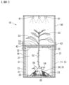
- the cultivation device 10 comprises a light-shielding housing 11 and a water level adjusting means 20 for supplying the cultivation liquid 25 at a constant water level, and is used together with a light source (not shown).
- a case in which potatoes, which are root vegetables, are cultivated among the entire plant body 50 will be described.
- a mounting table 30 is provided on the bottom surface of the light-shielding housing 11 , and inner bodies 31 , 32 are provided on the inner side surface of the mounting table 30 and the inner surface of the cover body 15 .
- the cultivation device 10 and the cultivation method for the plant body 50 according to the present invention soil is not required, so there is no location restriction and anyone can cultivate a desired plant anywhere, anytime.
- the root system is not hidden by the soil, it is possible to directly observe the function of the root system, particularly the root hairs, which will further advance research into plant ecology.
- the same manufacturing method is used consistently from research and development to commercialization and business (regional implementation and social implementation), the time required for implementation and industrialization is shortened and collaboration with all cutting-edge technologies (IT, of course, optical technology, nanotechnology, gene editing technology, etc.) is easily possible.
- the light-shielding housing 11 is formed of a light-shielding housing main body 12 and a cover body 15 that covers an upper opening of the light-shielding housing main body 12 .
- the light-shielding housing body 12 is a box with a roughly U-shaped cross section, and an opening 13 on one side of the light-shielding housing body 12 is provided with a door 14 that can be opened and closed from the top, but it is preferable to provide the door 14 as needed. Opening and closing the door 14 makes it easy to observe and manage the entire plant 50 cultivated within the light-shielding housing 11, for example, potato seed tubers 51, and makes it easy to harvest the baby tubers 54 that have emerged and grown.
- the boundary between the light-shielding housing body 12 and the cover 15, and the boundary between the opening 13 and the door 14 are sealed structures that prevent light from entering from the outside.
- the shape and size of the light-shielding housing 11 depend on the plant body 50 to be cultivated, but are not limited as long as it has a spatial area that can contain the root system of the plant body 50 and grown underground storage organs (storage roots (e.g., sweet potato, yam, radish, turnip, carrot, burdock, ginseng), underground stems (e.g., potato, taro, onion, garlic, turmeric), etc.).
- storage roots e.g., sweet potato, yam, radish, turnip, carrot, burdock, ginseng
- underground stems e.g., potato, taro, onion, garlic, turmeric
- a spatial area capable of containing the root system, grown underground storage organs and underground stems of the plant body 50 to be cultivated it is not limited to a rectangular parallelepiped shape and may be, for example, a cube, a cylinder, a truncated cone or a truncated pyramid, or, in longitudinal section, a cylindrical shape that is, for example, approximately semicircular, approximately triangular, approximately trapezoidal or approximately hexagonal, and of course, can be selected appropriately depending on the cultivated plant and cultivation environment.
- the cover 15 has a shape capable of covering the upper opening of the light-shielding housing main body 12 to provide light shielding, and is composed of two plates that can be divided into two, but may be formed of one single plate. If the cover 15 can be divided into two, it becomes easier to manage and take in and out the entire plant 50 to be cultivated. In particular, it is preferable because when the root system of the entire plant 50 swells, the door 14 can be opened to observe the root system of the entire plant 50, and it becomes easier to collect the plant 50.
- the cover 15 has a through hole 16 in the center through which the stem 52 of the entire plant 50 can pass.
- the through hole 16 may be formed, for example, as a round hole, an elliptical hole, a triangular hole, a square hole, a slit-shaped long hole, or an appropriate combination of these.
- the through-hole 16 not only passes through the above-ground part of the plant 50 to support the stem 52 of the plant 50, but also plays a role in taking in light.
- the position of the through-hole 16 is not particularly limited, but is preferably on the central axis of the light-shielding housing 11.
- the shape of the through-hole 16 is not particularly limited, and the external dimensions thereof may be any size that can accommodate the trunk or stem 52 of the plant 50 to be cultivated, and are, for example, 1 to 10 cm.
- the diameter of the through-hole 16 can be formed to be 15 to 65 mm.
- the light-shielding housing 11 is sealed except for the through-hole 16 so as to prevent light from entering from the outside.
- the through-hole 16 is a long hole in the shape of a slit, when the stem of the plant as a whole 50 grows and leaves emerge from the through-hole 16, it is preferable to prevent light from entering by attaching a shading sheet to the entire plant as a whole 50 except for the stem. This is to prevent the stolons generated from the potato from being exposed to light and transforming into stems.
- the water level adjustment means 20 may be, for example, a ball tap, but is not limited to this.
- it may be an adjustment means using a combination of a water level sensor and an electromagnetic valve.
- a cultivation liquid 25 whose level is adjusted by a water level adjustment means 20 is stored on the bottom surface of the light-shielding housing 11 .
- the water level adjusting means 20 may inject the cultivation liquid 25 directly into the light-shielding housing 11 through a water supply port (not shown), or may supply the cultivation liquid 25 to the inner side of the light-shielding housing 11 through a supply pipe 23. This is to prevent the nutrients in the cultivation liquid 25 from being unevenly distributed, and to ensure uniform growth of the entire plant 50.
- the cultivation liquid 25 may be water or a nutrient solution containing nutrients required for the growth of the entire plant to be cultivated.
- the cultivation liquid 25 may be stagnant water, and the cultivation device 10 does not require a running water mechanism or an oxygen supply mechanism, but adding these mechanisms is not excluded.
- the support table 30 be formed so that the liquid-phase roots can be immersed in the liquid while the enlarged parts are placed on it.
- the mounting table 30 may be formed from the same material as the inner bodies 31, 32 described below, but is not limited to this.
- the mounting table 30 may be formed from a stainless steel bar material shaped into a so-called lattice shape.
- the plant body 50 to be cultivated for example, potato seed tubers 51, may be of any material or shape as long as the lower surface of the plant body 50 can grow without being deeply immersed in the cultivation liquid 25.
- the inner bodies 31, 32 are used to maintain constant humidity and temperature within the light-shielding housing 11 by wicking up the cultivation liquid 25 stored in the light-shielding housing 11 through capillary action and evaporating it.
- the material of the inner body 31 can be made from an organic solid material, a non-metallic inorganic solid material, pulp, paper, woven fabric, non-woven fabric, a microporous body, or the like, either alone or in combination.
- the inner bodies 31, 32 may be a microporous fired product that is a fired product of a non-metallic inorganic solid material, includes communicating pores that are voids, has an average pore size of 3 ⁇ m or less, and pores with a pore size of 3 ⁇ m or less account for 70% or more of all voids by volume, and has a porosity of 10 to 80% (vol/vol) relative to the entire fired product.
- the inner surfaces 31 and 32 have the function of stabilizing the humidity and temperature inside the light-shielding housing 11 .
- the humidity is adjusted within the range of 20 to 100%, which is the humidity range when the plant as a whole 50 is grown.
- the temperature is a temperature appropriate for the plant body 50 to be cultivated, and is regulated naturally or externally by a temperature control device.
- the cultivation device 10 of the present invention does not necessarily need to be equipped with a temperature control device, but may be equipped with one as necessary.
- the inner bodies 31, 32 having such a function have a water absorption capacity capable of retaining, for example, at 20° C., 0.005 to 500 times, preferably 0.01 to 100 times, more preferably 0.025 to 50 times, and most preferably 0.05 to 5 times (weight/weight) of water per unit weight of the material forming the inner bodies 31, 32.
- the material forming the inner bodies 31, 32 is not particularly limited as long as it is a microporous body having, for example, communicating pores with a pore size of 0.02 to 900 ⁇ m, preferably 0.05 to 80 ⁇ m, more preferably 0.1 to 9 ⁇ m, and most preferably 0.2 to 5 ⁇ m, and a porosity (volume/volume) of 0.05 to 1, preferably 0.2 to 0.4, relative to the microporous body.
- the inner bodies 31, 32 may be any material that has the above characteristics, but are preferably made of a material that is resistant to various cultivation conditions or medium conditions such as high-temperature and high-pressure sterilization using an autoclave, strong alkalinity, strong acidity, high temperature, low temperature, high salt concentration, pressurization, decompression, organic solvents, radiation, or gravity.
- cultivation conditions or medium conditions such as high-temperature and high-pressure sterilization using an autoclave, strong alkalinity, strong acidity, high temperature, low temperature, high salt concentration, pressurization, decompression, organic solvents, radiation, or gravity.
- examples of such materials include porous bodies obtained by kneading, molding, and firing non-metallic inorganic solid materials such as No. 10 clay, Porcelain No.
- non-metallic inorganic solid material is to be a microporous porous body that easily absorbs and releases moisture, it is preferable to fire it with, for example, 50 to 60% by weight of petalite, alumina, etc.
- the petalite preferably contains 76.81% by weight of SiO2, 16.96% by weight of Al2O2, 4.03% by weight of LiO2, 0.26% by weight of K2O, and 1.94% by weight of unavoidable impurities.
- the non-metallic inorganic solid material may also contain powdered inorganic foam.
- the inner bodies 31 and 32 used in the cultivation device 10 according to the present invention are made of a material that does not substantially lose its strength or change its shape even when it absorbs water.
- ceramics made of non-metallic inorganic materials have a stable structure, inner bodies 31 and 32 made of paper or cloth are also useful depending on the plant to be cultivated.
- the molding method of the nonmetallic inorganic solid material may be, for example, casting, extrusion, press molding, wheel casting, or other molding methods known in the art, with extrusion molding being particularly preferred from the standpoint of mass production and cost reduction. Drying after molding may be performed using the usual methods and conditions known in the art.
- the subsequent firing of the molded body is not particularly limited as long as it is performed under the usual conditions and methods, but for example, oxidation firing, which is likely to produce the desired voids, may be selected, and the firing temperature is 1000°C to 2000°C, preferably 1100°C to 1500°C, more preferably 1150°C to 1250°C, and most preferably 1200°C. If the firing temperature of the nonmetallic inorganic solid material is less than 1000°C, sulfur components are likely to remain, while if it exceeds 2000°C, the desired water absorption cannot be obtained.
- methods for molding microporous bodies made from open-cell plastic foam include, for example, melt foam molding, solid-phase foam molding, and cast foam molding.
- the main steps in melt foam molding are melt kneading, unfoamed sheet molding, heating foaming or extrusion foaming, cooling, cutting, and processing.
- solid-phase foam molding the polymer is foamed in a solid or near-solid state.
- cast foam molding liquid raw materials (monomers or oligomers) are used and foamed by casting while reacting in the air.
- a blowing agent is generally used to foam open-cell plastic foam.
- the cultivation apparatus 10 may further include a support or sleeve for supporting the entire plant body 50 . Furthermore, when the cultivation of the whole plant 50 to be cultivated is started from the form of a seed, bulb or seed potato, the cultivation device 10 may be provided with a mounting table 30 for the seeds, bulbs or seed potatoes. The dimensions of the mounting table 30 may be such that the target seeds, bulbs or seed potatoes can be mounted thereon and the mounting table 30 can be accommodated inside the light-shielding housing 11.
- the cultivation device 10 may be provided with a support (not shown) that guides the plant main body, such as the trunk, stem, branches and leaves generated from the seed, bulb or seed potato, to grow toward the light from the through-hole 16 formed in the lid 15 during the period when the plant main body is less than the height of the light-shielding housing 11.
- the plant body 50 may be provided with a support (not shown) that guides the plant body 50 to grow toward the light from the through hole 16 formed in the lid body 15.
- a support table may be provided on which the enlarged parts are placed while the liquid-phase roots are immersed in the cultivation liquid.
- the method for cultivating a whole plant according to the present invention comprises the steps of: A method for cultivating a whole plant using the above-mentioned cultivation device for a whole plant, the method comprising the steps of: providing an inner surface body exhibiting capillary force on at least a part of an inner surface of a light-shielding housing that stores a liquid, and forming a spatial area capable of containing a root system of the whole plant within the light-shielding housing; A step of supplying a cultivation liquid to the light-shielding housing before or after the step of forming the spatial region;
- the present invention provides a cultivation method including the steps of: growing roots in a cultivation liquid stored in a light-shielding housing, the roots absorbing moisture and nutrients from a liquid phase; and growing roots in moisture and oxygen present inside a spatial region of the light-shielding housing, the roots absorbing oxygen from a gas phase.
- the main purpose of the cultivation method for the plant body 50 according to the present invention is to create an environment suitable for growing the plant body 50 by placing the roots of the plant body 50, particularly the enlarged parts, i.e., storage roots and rhizomes, on a mounting stand 30 placed on the bottom of the cultivation liquid stored in a light-shielding housing 11.
- the term "environment suitable for growing the entire plant” refers to a space area in which the humidity is kept at 20 to 100% RH without the need for soil, and the roots of the entire plant 50 to be cultivated can be grown separately into a "liquid-phase root” area that mainly absorbs moisture and nutrients and a "gas-phase root” area that mainly absorbs oxygen.
- This space area contains moisture from the cultivation liquid 25 stored on the bottom surface of the light-shielding housing 11 and gas components such as oxygen, nitrogen, and carbon dioxide.
- the gas components can be ventilated between the inside and outside of the light-shielding housing 11 through the through holes 16.
- the temperature in the space area only needs to be within a temperature range suitable for the entire plant 50 to be cultivated, and since the root system is incompletely isolated from the outside air, there is no sudden temperature change, and a special temperature control mechanism is not required, although one may be attached as necessary.
- the moisture is supplied directly from the cultivation liquid 25 stored on the bottom surface of the light-shielding housing 11, and/or from the cultivation liquid 25 that is sucked up by capillary action through the communication holes, which are voids present in the inner bodies 31, 32 installed on the inside surface of the light-shielding housing 11.
- the liquid-phase roots are immersed in the cultivation liquid 25 stored in the bottom surface of the light-shielding housing 11 , and the air-phase roots do not come into contact with the cultivation liquid 25 .
- the cultivation method for the plant body 50 according to the present invention does not require any of the roots to grow in contact with the inner surface of the light-shielding housing 11 having the inner bodies 31, 32. However, it is not excluded that the elongated roots may come into contact with the inner surface of the light-shielding housing 11.
- the cultivation liquid 25 stored in the light-shielding housing 11 is water or a nutrient solution containing nutrients required for the growth of the plant 50, which is the subject of cultivation, and is stagnant water that does not need to flow and is prone to lack of dissolved oxygen. Therefore, in the present invention, in order to supply oxygen, there is no need for a flowing water mechanism for flowing the cultivation liquid 25, nor for an oxygen supply mechanism for directly supplying oxygen to the cultivation liquid 25. This is because the cultivation method according to the present invention allows the "air-phase roots", which mainly absorb oxygen, to be sufficiently grown.
- the nutrients required for the growth of the plant include carbon, hydrogen, and oxygen, as well as essential macroelements such as at least nitrogen, phosphate, potassium, calcium, magnesium, and sulfur, and further include essential trace elements such as iron, manganese, boron, zinc, molybdenum, copper, chlorine, and nickel, as well as useful elements such as silicon, sodium, and cobalt.
- the cultivation of the plant 50 can start from a seed, bulb or seed tuber, which can be rooted and germinated in the cultivation device 10 according to the present invention.
- the cultivation can start from a seedling.
- the inner bodies 31, 32 to be placed on the inner surface of the light-shielding housing 11 is a sintered product of a non-metallic inorganic solid material, which contains interconnecting holes that are voids, has a porosity of 10 to 80% (vol/vol) relative to the entire sintered product, has an average pore size of 3 ⁇ m or less, and pores with a pore size of 3 ⁇ m or less account for 70% or more of the total voids by volume.
- the second embodiment of the cultivation device 10 is configured such that the light-illuminating housing 40 is placed on the light-shielding housing 11 via a positioning frame 42 having a substantially T-shaped cross section. It is preferable to assemble the light-shielding housing 11, the light-illuminating housing 40, and the positioning frame 42 so that they can be separated from each other as necessary.
- a light source 41 installed on the ceiling surface of the light-illuminating housing 40 irradiates light toward the cover 15 of the light-shielding housing 11 , thereby growing a plant 50 .
- the shape of the light-illuminating housing 40 is not limited to a rectangular parallelepiped shape, and is preferably a shape that can be stacked on the light-shielding housing 11, and may be a cube or a cylindrical shape with a semicircular cross section, a trapezoidal cross section, an inverted trapezoidal cross section, a triangular cross section, or a hexagonal cross section. Furthermore, it is even more preferable that the shape of the light-illuminating housing 40 is a shape that can be stacked on another light-shielding housing 11.
- the light source 41 is not limited to being installed on the ceiling surface of the illumination housing 40, but may be installed on the inner surface, and the installation position, number, and installation direction can be selected appropriately as necessary.
- the light source 41 is not limited to a light source having an elongated shape, and it is of course possible to use a light source that irradiates light in a spot manner, or a combination of these.
- the light source 41 may be the same as that used in the first embodiment, but taking into consideration the temperature rise inside the illuminated housing 40, it does not have to be the same as that used in the first embodiment, and different light sources may be used in combination. Examples of the light source 41 include an LED lamp, a fluorescent lamp, a halogen lamp, a sodium lamp, a metal halide lamp, and an ultraviolet lamp.
- the second embodiment is substantially the same as the first embodiment except for the illuminated housing 40, so the same parts are given the same numbers and descriptions are omitted.
- the third embodiment of the cultivation device 10 has a light-illuminating housing 40 mounted on a light-shielding housing 11, similar to the second embodiment described above.
- the light-shielding housing 11 is provided with a door 14 that opens downward, and a lid 15 has three through holes 16 at a predetermined pitch.
- the light-shielding housing body 12 and the water level adjustment means 20 communicate with each other via two water supply ports 17, 17 (see FIG. 8).
- An illumination housing 40 is mounted on the upper surface of the light-shielding housing 11.
- a water storage tank 43 is attached to the illumination housing 40, which is connected to the water level adjustment means 20 via a connection hose 24 and supplies the cultivation liquid 25.
- a light source (not shown) is installed on the ceiling surface of the illumination housing 40.
- the temperature is a temperature appropriate for the plant body 50 to be cultivated, and is regulated from the outside, either naturally or by a temperature control device. Therefore, it is not necessary to attach a temperature control device to the cultivation device 10 of the present invention, but it may be attached as necessary.
- the cultivation device 10 according to the second and third embodiments has the advantage that multiple cultivation devices 10 can be stacked together, making it possible to make effective use of land and allowing it to be used even on small plots of land.
- a fourth embodiment of the cultivation device 10 according to the present invention is a case in which a light-shielding housing 11 is mounted on a support frame 60, as shown in FIG.
- the support frame 60 has a rectangular bottom plate 61 and supports 62 at the four corners of the bottom plate 61.
- the outer periphery of the bottom plate 61 is bent and raised to form ribs to increase the mechanical strength.
- a reinforcing plate 63 is provided between adjacent supports 62.
- the illumination unit 64 incorporates, for example, an LED (not shown) as a light source, and is equipped with a control unit 65.
- the illumination unit 64 irradiates light from the incorporated LED to the light-shielding housing 11 via a scattering plate (not shown) attached to the lower surface of the illumination unit 64.
- the scattering plate diffuses the light, thereby making the amount of light irradiated by the LED uniform.
- a holder 26 with a T-shaped cross section and a holder 27 with an L-shaped cross section are attached to the inside surface of the light-shielding housing 11.
- the holder 26 and the holder 27 can be inserted through the inner body 31 (not shown) to allow for detachable attachment.
- the attachment and removal of the inner body 31 is simplified, improving workability.
- This has the advantage of facilitating replacement and cleaning of the inner body 31, improving maintainability.
- the holders 26 and 27 are not limited to being attached to the inside surface of the light-shielding housing main body 12, but may also be attached to the ceiling surface of the lid 15. Furthermore, it goes without saying that only the holder 26 or only the holder 27 may be attached to the light-shielding housing 11 and used.
- the inner body 31 does not necessarily have to be provided on the inner side and ceiling of the light-shielding housing 11, but may be provided in the center of the bottom surface like a pillar or a partition wall. By providing the inner body 31 in this manner, it is possible to maintain the humidity in the internal space more uniformly. Furthermore, the inner body 31 is not limited to being installed on the bottom surface of the light-shielding housing 11 as a mounting stand, but may be laid over the entire bottom surface of the light-shielding housing 11. In this case, the inner body 31 used preferably has not only the desired capillary force but also water retention capacity that can supply the cultivation liquid to the entire plant. Examples of the inner body 31 include paper, nonwoven fabric, foamed resin, and microporous bodies.
- microporous bodies include those disclosed in International Publication No. WO2004/101736.
- the inner body 31 may be disposed at an angle by leaning it against the inner surface of the light-shielding housing 11.
- the through-hole 16 of the lid body 15 is provided along the outer periphery of the lid body 15. If the inner body 31 is disposed as described above, it becomes easier to grow, for example, carrots, radishes, burdock, and the like.
- the same parts are given the same numbers and their explanations are omitted.
- the fifth embodiment of the cultivation device 10 is a case in which multiple hanging fixtures 28, for example formed by bending wire, are hung at a specified pitch on both opposing side edges of the opening edge of the light-shielding housing main body 12.
- the lid body 15 is formed by hanging, for example, two pieces of black plastic cardboard butted together on the hanging fixtures 28.
- cutouts are formed at opposing positions on the butted end faces of the plastic cardboard to form through holes.
- the plastic cardboard used is not limited to being black, and may be, for example, white and translucent. If white translucent plastic cardboard is used, it is preferable to cover the surface with, for example, aluminum foil to block out light.
- the lid 15 is formed using lightweight plastic cardboard, which has the advantage of making the entire cultivation device lighter. Also, according to this embodiment, an internal space of an appropriate height can be easily formed according to the cultivated plants, which has the advantage of allowing a wide variety of plants to be cultivated by sharing one light-shielding housing main body 12. This has the advantage of making it convenient since it is no longer necessary to change the shape of the light-shielding housing 11 for each cultivated plant. In addition, the same parts are given the same numbers and their explanations are omitted.
- the cultivation device for a whole plant comprises: It is composed of a light-shielding housing 11 having at least one through hole 16 on the ceiling surface and storing cultivation liquid 25, and inner surfaces 31, 32 exhibiting capillary force and installed on at least a part of the inner surface of the light-shielding housing 11.
- the cultivation device 10 for a whole plant according to the second aspect of the present invention is the cultivation device 10 for a whole plant according to the first aspect,
- the light-shielding housing 11 is connected to a water level adjusting means 20 for adjusting the water level of the cultivation liquid 25 .
- the cultivation device 10 for a plant body 50 according to a third aspect of the present invention is the cultivation device 10 for a plant body 50 according to either the first or second aspect,
- the light-shielding housing 11 is configured to include a box-shaped light-shielding housing main body 12 and a detachable cover 15 that covers an upper opening of the light-shielding housing main body 12 .
- the cultivation device 10 for a plant body 50 according to a fourth aspect of the present invention is the cultivation device 10 for a plant body 50 according to the third aspect,
- the cover 15 is suspended from a plurality of suspenders 28 that are suspended across opposing opening edge portions of the light-shielding housing body 12 .
- the cultivation device 10 for a plant body 50 according to a fifth aspect of the present invention is the cultivation device 10 for a plant body 50 according to any one of the first to fourth aspects,
- the through hole 16 may be a long hole having a slit shape.
- the sixth aspect of the present invention relates to a cultivation device 10 for a plant body 50, which is the cultivation device 10 for a plant body 50 according to any one of the first to fifth aspects,
- An openable and closable door 14 may be provided on at least one of the sides of the light-shielding housing 11 .
- the seventh aspect of the present invention relates to a cultivation device 10 for a plant body 50, which is the cultivation device 10 for a plant body 50 according to any one of the first to sixth aspects,
- the inner body 31 may be provided on the entire inner surface of the light-shielding housing 11 .
- the cultivation device 10 for a plant body 50 according to an eighth aspect of the present invention is the cultivation device 10 for a plant body 50 according to any one of the first to seventh aspects,
- An inner body 32 may be provided on the inner surface of the cover 15 of the light-shielding housing 11 , excluding the through-hole 16 .
- the cultivation device 10 for a plant body 50 according to a ninth aspect of the present invention is the cultivation device 10 for a plant body 50 according to any one of the first to eighth aspects,
- An inner surface body 32 having a water-retaining capacity capable of supplying the cultivation liquid to the entire plant may be laid on the entire bottom surface of the light-shielding housing 11 .
- the cultivation device 10 for a plant body 50 according to a tenth aspect of the present invention is the cultivation device 10 for a plant body 50 according to any one of the first to ninth aspects,
- the inner body 32 may be removably installed on the light-shielding housing 11 via at least one of the holders 26 and 27 attached to at least the inner surface of the light-shielding housing 11 .
- the cultivation device 10 for a plant body 50 according to an eleventh aspect of the present invention is the cultivation device 10 for a plant body 50 according to any one of the first to tenth aspects,
- the inner body 32 may be disposed at an angle against the inner surface of the light-shielding housing 11 .
- the cultivation device 10 for a plant body 50 according to a twelfth aspect of the present invention is the cultivation device 10 for a plant body 50 according to any one of the first to eleventh aspects,
- a platform 30 on which the plant body 50 is placed may be provided on the bottom surface of the light-shielding housing 11 .
- the cultivation device 10 for a plant body 50 according to a thirteenth aspect of the present invention is the cultivation device 10 for a plant body 50 according to the twelfth aspect,
- the mounting table 30 may be formed from the same material as the inner bodies 31 and 32 .
- the cultivation device 10 for a plant body 50 according to a fourteenth aspect of the present invention is the cultivation device 10 for a plant body 50 according to the twelfth aspect,
- the mounting table 30 may be made of a wooden slatted floor.
- the cultivation device 10 for a plant body 50 according to a fifteenth aspect of the present invention is the cultivation device 10 for a plant body 50 according to any one of the first to fourteenth aspects, It is preferable that the inner bodies 31, 32 are sintered products of a non-metallic inorganic solid material, contain communicating holes which are voids, have a porosity of 10 to 80% (vol/vol) relative to the entire sintered product, have an average pore size of 3 ⁇ m or less, and have pores with a pore size of 3 ⁇ m or less account for 70% or more of the total voids by volume.
- the cultivation device 10 for a plant body 50 according to a sixteenth aspect of the present invention is the cultivation device 10 for a plant body 50 according to any one of the first to fifteenth aspects,
- An illumination housing 40 including a light source 41 that irradiates light toward the upper surface of the light-shielding housing 11 may be stacked on the light-shielding housing 11 .
- the cultivation device 10 for a plant body 50 according to a seventeenth aspect of the present invention is the cultivation device 10 for a plant body 50 according to any one of the first to fifteenth aspects,
- An illumination unit 64 including a light source that irradiates light toward the upper surface of the light-shielding housing 11 may be disposed above the light-shielding housing 11 .
- a method for cultivating a plant body 50 according to an eighteenth aspect of the present invention includes the steps of: A method for cultivating a plant body 50 using the cultivation device 10 for a plant body 50 described in any one of the first to seventeenth aspects, the method comprising the steps of: providing an inner surface body 31, 32 exhibiting capillary force on at least a part of an inner surface of a light-shielding housing 11 that stores at least a cultivation liquid 25, and forming a spatial area capable of containing a root system of the plant body 50 within the light-shielding housing 11; a step of supplying a cultivation liquid 25 to the light-shielding housing 11 before or after the step of forming the space area; The method includes the steps of: growing roots that absorb moisture and nutrients from the liquid phase in the cultivation liquid 25 stored in the light-shielding housing 11; and growing roots that absorb oxygen from the gas phase in the moisture and oxygen present inside the spatial area of the light-shielding housing 11.
- a method for cultivating a plant body 50 according to a nineteenth aspect of the present invention includes the steps of: A method for cultivating a plant body 50 according to an eighteenth aspect, comprising: The plant body 50 is placed on a mounting table 30 installed on the bottom surface of a light-shielding housing 11 and cultivated.
- a method for cultivating a plant body 50 according to a twentieth aspect of the present invention includes the steps of: A method for cultivating a plant body 50 according to any one of the eighteenth and nineteenth aspects, comprising:
- the cultivation liquid 25 stored in the light-shielding housing 11 is water or a nutrient liquid containing nutrients required for the growth of the plant body 50 that is the subject of cultivation, and is characterized by being stagnant water.
- a method for cultivating a plant body 50 according to a twenty-first aspect of the present invention includes the steps of: A method for cultivating a plant body 50 according to the twentieth aspect,
- the nutrients are characterized by being essential macroelements selected from nitrogen, phosphate, potassium, calcium, magnesium and sulfur, essential trace elements selected from iron, manganese, boron, zinc, molybdenum, copper, chlorine and nickel, or useful elements selected from silicon, sodium, cobalt, etc.
- Example 1 (1) Cultivation Device
- the plant as a whole according to the present invention is intended to cultivate a plant with a swollen root system.
- the light-shielding housing of the cultivation device must have a shape, size, and weight that can support the plant to be cultivated and accommodate the swollen root system.
- the plant as a whole cultivation device according to Example 1 is composed of a light-shielding housing with a length of 90 cm, a width of 30 cm, and a height of 30.5 cm, as shown in FIG. 9, and a light source that irradiates light to the cultivated plant.
- the removable lid covering the light-shielding housing body had a through hole, which was a long hole measuring 5 cm in width and 66 cm in length, along the center line in the length direction in order to support the plant. After the potato stem grew and passed through the through hole, the rest of the hole was closed with light-shielding tape, except for the part of the through hole where the stem had passed.
- the light-shielding housing according to the first embodiment is not provided with a door.
- An inner body measuring 18.0 cm wide, 30.8 cm long and 1.0 cm thick was attached to the inner surface of the light-shielding housing and the ceiling surface of the lid, with the dimensions appropriately adjusted. The function and characteristics of the inner body will be described in detail later.
- Three mounting tables were installed at a predetermined pitch on the bottom surface of the light-shielding housing, located directly below the through-hole. The mounting tables were made by appropriately adjusting the dimensions of the above-mentioned inner body. The height of the mounting table was adjusted by increasing the number of inner bodies as required.
- the wavelength distribution contained in the light source was measured using a wavelength distribution measuring instrument (Gospectro, manufactured by Goyalab), and the monitor showing the measurement results of the wavelength distribution measuring instrument was photographed. The photographed results are shown in Figure 11.
- the horizontal axis is wavelength (unit: nm), and the vertical axis is spectral irradiance (unit: mW/m2/nm) indicating the amount of energy. From the measurement results, it was found that the spectral irradiance was maximum at a wavelength of 451 nm, and the maximum spectral irradiance was 393 mW/m2/nm.
- the material for the inner body made of the fired material used in the present invention was Mikawa clay for ceramic roofing tiles R2-6.
- the results of quantitative analysis of Mikawa clay for ceramic roofing tiles R2-6 are shown in Table 2.
- a microporous fired material (clay R2-6 for ceramic roofing tiles) was formed into a plate shape and fired in a gas kiln at a firing temperature of 1090°C for 13 hours and removed from the kiln for 30 hours to produce an inner body made of a microporous fired body.
- the manufacturing conditions for the inner body and the dimensions of the manufactured inner body are shown in Table 3.
- An electron microscope photograph of the cross section of the microporous fired body is shown in Figure 12.
- the porosity and pore composition of the inner surface of the microporous fired body were calculated for each sample by a filtration centrifugal method according to the following procedure.
- a target microporous sintered body sample is crushed to obtain a small sample piece (5 to 8 mm square, approximately 0.5 g) that can be caught in the middle of a microcentrifuge tube.
- the sample piece is dried until it reaches a constant weight, and the dry weight Ws of the sample piece is measured, and the dry weight Wt of the microcentrifuge tube is measured.
- the sample pieces are again placed into the microcentrifuge tube with the water still stored in it, and centrifuged at 5,500 rpm for 5 minutes.
- the sample pieces are then removed and the weight Wb of the microcentrifuge tube with water stored in the bottom is measured.
- the sample pieces are again placed into the microcentrifuge tube with the water still stored in it, and centrifuged at 8,000 rpm for 5 minutes.
- the sample pieces are then removed and the weight Wc of the microcentrifuge tube with water stored in the bottom is measured.
- the sample pieces are again placed into the microcentrifuge tube with the water still stored in it, and centrifuged at 10,500 rpm for 5 minutes. The sample pieces are then removed and the weight Wd of the microcentrifuge tube with water stored in the bottom is measured.
- the distance from the center of rotation of the centrifuge to the free water surface was taken as the rotation radius, and the pore composition was calculated based on the centrifugal force vs. pore diameter table shown in Table 5.
- the free water surface was set to the center position of the top and bottom of the microcentrifuge tube, and the pore composition was calculated assuming that dehydration occurs from pores with a pore diameter of 3.5 ⁇ m or more at 3,000 rpm, from pores with a pore diameter of 1.0 ⁇ m or more at 5,500 rpm, from pores with a pore diameter of 0.5 ⁇ m or more at 8,000 rpm, and from pores with a pore diameter of 0.3 ⁇ m or more at 10,500 rpm.
- the results are shown in Table 6.
- the porosity of the entire sintered product which is a microporous sintered body, was approximately 13%.
- the results of electron microscope observation and pore composition measurements showed that the surface of the inner body, which is made of a microporous fired body, has interconnected pores with a pore size of 0.2 to 5 ⁇ m (average pore size 3 ⁇ m).
- the inner surface is not limited to a fired material, but may be made of a fibrous material, for example, a fibrous sheet of paper, woven fabric, nonwoven fabric or the like wrapped around a plate-shaped wire framework.
- the inner body can also be formed by compressing fibrous materials such as pulp and lint into a plate shape.
- the inner surface may be made of a resin material to form a microporous body with specific communicating pores, similar to the sintered body material.
- the potatoes cultivated using the cultivation device of the present invention grew well, and baby potatoes emerged from the seed potatoes. Furthermore, during the cultivation period, most of the liquid-phase roots and air-phase roots of the potatoes cultivated using the cultivation device of the present invention were not in contact with the inner surface of the light-shielding housing. The potatoes that were removed were in good condition, with no algae or other deposits adhering to them.
- the cultivation apparatus and cultivation method of the present invention can grow air-phase roots above the water surface using only stagnant water, without using complex water circulation equipment for cultivated plants, and at the same time, can grow liquid-phase roots underwater. That is, according to the present invention, it is possible to reproduce the environment of soil aggregate structure, which has been thought to affect good plant growth, without using soil. In addition, since the present invention does not use soil, at the end of cultivation, the roots of the plants are clean and free of soil, algae, etc., and it has been found that the plants can be shipped as is without the need for complicated cleaning work.
- Example 2 (1) Cultivation Apparatus
- a cultivation apparatus consisting of a light-shielding housing similar to that in Example 1 was used.
- Four mounting tables each made of an inner surface (thickness: 1.0 cm) were installed at a predetermined pitch on the bottom surface of the light-shielding housing located directly below the through-hole.
- the mounting tables were made by appropriately adjusting the dimensions of the inner surface described above.
- the height of the support base was raised by placing a sintered body made of the same material as the inner body and shaped like a flowerpot upside down to serve as a support base.
- the photographed results are shown in Figure 17.
- the horizontal axis is wavelength (unit: nm), and the vertical axis is spectral irradiance (unit: mW/m2/nm) indicating the amount of energy. From the measurement results, it was found that the spectral irradiance was maximum at a wavelength of 428 nm, and the maximum spectral irradiance was 198 mW/m2/nm.
- Inner Body The inner body according to the second embodiment is the same as that of the first embodiment, and therefore a description thereof will be omitted.
- the potatoes cultivated grew well, and baby potatoes emerged from the seed potatoes.
- the liquid-phase roots of the potatoes cultivated using the cultivation device of the present invention extended to the inner body installed on the inside surface of the light-shielding housing.
- Example 3 A light-shielding housing (RB1 type) of the same shape as in Example 1 was placed in a room set to a temperature of 22° C. and a humidity of 60%. Three LED lamps (6000 K (Kelvin)) were placed above the light-shielding housing and were lit for 14 hours for cultivation. As shown in FIG. 23, on June 6, 2023, two sprouted turmeric seeds were placed on a ceramic plate installed on the bottom of an RB1-type light-shielding housing, and the roots were shaded with a lid. Roots sprouted on the second day from the start date, and on the ninth day, the sprouts grew and aerial roots appeared. On the 21st day, the above-ground part passed through the through hole.
- 6000 K Kelvin
- FIG. 24 shows an enlarged view of the aerial roots that appeared on the 21st day
- FIG. 25 shows an enlarged view of the turmeric roots on the 121st day.
- Example 4 A light-shielding housing (RB1 type) of the same shape as in Example 1 was placed in a room set to a temperature of 22° C. and a humidity of 60%. Three LED lamps (6000 K (Kelvin)) were placed above the light-shielding housing and were lit for 14 hours for cultivation. As shown in FIG. 26, on May 22, 2023, sprouted seed ginger was placed on a ceramic plate installed on the bottom of an RB1 type light-shielding housing, and the roots were shaded with a lid. Roots sprouted on the 8th day from the start date, and liquid-phase roots grew on the 30th day. Leaves passed through the through holes on the 31st day, and aerial roots developed on the 36th day.
- 6000 K Kelvin
- FIG. 27 shows an enlarged view of the developed aerial roots on the 36th day
- FIG. 28 shows an enlarged view of the harvested ginger on the 136th day.
- Example 5 The roots of corn seedlings purchased as potted seedlings on April 26, 2023 were washed with water and the soil was removed. Meanwhile, an RB1 type box was installed in a cultivation box installed in a research building with a temperature set to 25 ° C. The cultivation box was equipped with a ventilation fan, and a high-pressure sodium lamp (FEC Sunlux Ace NH360LS manufactured by Iwasaki Electric Co., Ltd.) was lit for 12 hours. As shown in Fig. 29, corn seedlings were set upright on a wooden slatted mat installed on the bottom of an RB1 type box via clips on May 1. At this time, the tips of the roots of the corn seedlings were immersed in the cultivation liquid.
- a high-pressure sodium lamp FEC Sunlux Ace NH360LS manufactured by Iwasaki Electric Co., Ltd.
- FIG. 30 shows an enlarged view of the root on day 4
- FIG. 31 shows an enlarged view of the whole corn on day 79.
- Example 6 The roots of soybean seedlings purchased as potted seedlings on April 26, 2023 were washed with water and the soil was removed. Meanwhile, an RB1 type box was installed in a cultivation box installed in a research building set at a temperature of 25 ° C. The cultivation box was equipped with a ventilation fan, and a high-pressure sodium lamp (FEC Sunlux Ace NH360LS manufactured by Iwasaki Electric Co., Ltd.) was lit for 12 hours. As shown in Fig. 32, soybean seedlings were set upright on a wooden slatted mat installed on the bottom of an RB1 type box via clips on May 1. At this time, the tips of the roots of the soybean seedlings were immersed in the culture liquid.
- a high-pressure sodium lamp FEC Sunlux Ace NH360LS manufactured by Iwasaki Electric Co., Ltd.
- FIG. 33 shows a partial enlargement of the roots on day 4
- FIG. 34 shows an enlargement of all soybeans harvested on day 56.
- Example 7 (rapeseed) As shown in Fig. 35, the RB1 type box was placed in a room set at a temperature of 20.5°C and a humidity of 70%. Then, rapeseed seedlings that had been rooted from seeds were placed on a ceramic plate placed on the bottom of the RB1 type box. Next, two sheets of black plastic cardboard with a thickness of 4 mm were butted together and hung at a height of 15 cm from the bottom to support the stems of the rapeseed seedlings and shield the roots. The lighting was LED (SOLIDLITE EL-L01-LT104F-DQM-D2423) and was turned on for 12 hours, and cultivation began on June 30, 2023. Seven days after the start date, aerial roots appeared.
- LED SOLIDLITE EL-L01-LT104F-DQM-D2423
- Fig. 36 and Fig. 37 show enlarged views of growing seedlings and emerged aerial roots on the 7th day
- Fig. 38 and Fig. 39 show enlarged views of grown rapeseeds and roots on the 105th day.
- Example 8 (basil) As shown in FIG. 40, the RB1 type box was installed in a room set at a temperature of 20.5°C and a humidity of 70%. Then, basil seedlings rooted from seeds were placed on a ceramic plate placed on the bottom of the RB1 type box. Next, two 4 mm thick black plastic cardboard sheets were butted together and hung at a height of 15 cm from the bottom to support the stems of the basil seedlings and shield the roots. LEDs (SOLIDLITE EL-L01-LT104F-DQM-D2423) were used as lighting and were turned on for 12 hours, and cultivation began on June 30, 2023. Aerial roots appeared 7 days after the start of cultivation.
- Fig. 41 shows an enlarged view of the aerial roots that appeared on day 7.
- Figs. 42, 43 and 44 show enlarged views of the basil plants grown on day 105, the harvested seeds and the roots, respectively.
- Example 8 As shown in FIG. 45, an RB1 type box was installed in a room set at a temperature of 20.5°C and a humidity of 70%. Then, a mint seedling rooted by cutting was placed directly on the bottom of the RB1 type box. Next, two 4 mm thick black plastic cardboard sheets were butted together and hung at a height of 10 cm from the bottom to support the stem of the mint seedling and shield the root. An LED (SOLIDLITE EL-L01-LT104F-DQM-D2423) was used as the lighting and turned on for 12 hours, and cultivation began on August 2, 2023. Aerial roots appeared 7 days after the start of cultivation.
- Fig. 46 shows an enlarged view of the aerial roots that appeared on day 7.
- Figs. 47 and 48 show enlarged views of the grown mint and maturing seeds on day 70, respectively.
- Example 10 (Perilla) As shown in FIG. 49, an RB1 type box was installed in a room set at a temperature of 20.5°C and a humidity of 70%. Then, a perilla seedling rooted by cutting was placed on a ceramic plate placed on the bottom of the RB1 type box. Next, two 4 mm thick black plastic cardboard sheets were butted together and hung at a height of 12 cm from the bottom to support the stem of the perilla seedling and shield the roots. An LED (SOLIDLITE EL-L01-LT104F-DQM-D2423) was used as the lighting lamp and turned on for 12 hours, and cultivation began on July 13, 2023.
- SOLIDLITE EL-L01-LT104F-DQM-D2423 was used as the lighting lamp and turned on for 12 hours, and cultivation began on July 13, 2023.
- Figure 50 shows an enlarged view of the installation status of the perilla seedlings
- Figure 51 shows a partial enlarged view of the aerial roots that appeared on the 14th day
- Figure 52 shows an enlarged view of the roots on the 56th day
- Figure 53 shows an enlarged view of the seeds harvested on the 56th day.
- Example 11 (strawberry) As shown in FIG. 54, an RB1 type box was installed in a room set at a temperature of 20.5°C and a humidity of 70%. Then, strawberry seedlings that had been divided and rooted from runners were placed on a ceramic plate placed on the bottom of the RB1 type box. Next, two sheets of black plastic cardboard with a thickness of 4 mm were butted together and hung at a height of 12 cm from the bottom to support the stems of the strawberry seedlings and shield the roots. LEDs (SOLIDLITE EL-L01-LT104F-DQM-D2423) were used as lighting and were turned on for 12 hours, and cultivation began on July 13, 2023.
- LEDs SOLIDLITE EL-L01-LT104F-DQM-D2423
- FIG. 55 shows an enlarged view of a portion of the aerial roots that appeared on the 14th day
- FIG. 56 shows an enlarged view of strawberries harvested on the 70th day.
- Example 12 (Tricolor orange) As shown in Fig. 57, the roots of trifoliate orange seedlings purchased as potted seedlings were washed with water and the soil was removed. Meanwhile, a light-shielding housing was installed as a cultivation device in a room set at a temperature of 22°C and a humidity of 60%.
- the light-shielding housing used had the same structure as that of the first embodiment (referred to as RB2 type) except that the through holes were round holes.
- Three LED lamps (6000K (Kelvin)) were placed above the light-shielding housing (RB2 type) and were lit for 14 hours for cultivation.
- FIG. 58 shows an enlarged view of the aerial roots that appeared on the 42nd day.
- Example 13 (Tea plant) As shown in Figure 59, the roots of tea plant seedlings purchased as pot seedlings were washed with water and the soil was removed. Meanwhile, RB2 type was placed in a room set at a temperature of 22°C and a humidity of 60%. Three LED lamps (6000K (Kelvin)) were placed above RB2 type and were cultivated by turning them on for 14 hours. On August 31, 2023, the roots of the tea plant were placed on a ceramic plate installed on the bottom of the RB2 type and the roots were shaded with a lid. On the 14th day from the start date, the liquid phase roots grew, and on the 28th day, the buds swelled and aerial roots appeared.
- 6000K Kelvin
- FIG. 60 shows an enlarged view of the developed air-phase roots and liquid-phase roots on the 35th day
- FIG. 61 shows an enlarged view of a flower that has opened on the 40th day.
- Example 14 Passion fruit
- the roots of the passion fruit seedlings purchased as potted seedlings were washed with water and the soil was removed. Meanwhile, the RB2 type was placed in a room set at a temperature of 22°C and a humidity of 60%. Three LED lamps (6000K (Kelvin)) were placed above the RB2 type and were cultivated by turning them on for 14 hours.
- passion fruit seedlings were placed on a ceramic plate installed on the bottom of the RB2 type, and the roots were shaded with a lid. The growth of liquid roots was confirmed on the 8th day from the start date, and the appearance of air roots was confirmed on the 25th day.
- FIG. 63 shows an enlarged view of the aerial roots that appeared on the 25th day
- FIG. 64 shows a partial enlarged view of the developed aerial roots on the 73rd day.
- Example 15 As shown in Fig. 65, the roots of potted fig seedlings were washed with water and the soil was removed. Meanwhile, an RB2 type box was placed in a room set at a temperature of 22°C and a humidity of 60%. Three LED lamps (6000K (Kelvin)) were placed above the RB2 type box and were cultivated by turning them on for 14 hours. On July 24, 2023, a fig seedling was placed on a ceramic plate installed on the bottom of the RB2 type, and the roots were shaded with a lid. On the 8th day from the start date, liquid phase roots appeared, on the 30th day the leaf area of the top leaf expanded, and on the 36th day, aerial phase roots appeared.
- 6000K Kelvin
- FIG. 66 shows an enlarged view of the air roots that emerged on the 36th day
- FIG. 67 shows an enlarged view of the air roots that emerged above the liquid surface on the 66th day.
- Example 16 (Day lily) As shown in Fig. 68, the roots of the potted Glycyrrhiza uralensis seedlings were washed with water and the soil was removed. Meanwhile, the RB2 type was placed in a room set at a temperature of 22°C and a humidity of 60%. Three LED lamps (6000K (Kelvin)) were placed above the RB2 type and were cultivated by turning them on for 14 hours. On July 20, 2023, a Glycyrrhiza uralensis seedling was placed on a ceramic plate installed on the bottom of the RB2 type, and the roots were shaded with a lid.
- 6000K Kelvin
- FIG. 69 shows an enlarged view of the aerial roots that appeared on the 18th day
- FIG. 70 shows an enlarged view of the enlarged roots on the 82nd day.
- Example 17 (Cotton) As shown in Fig. 71, the roots of potted cotton seedlings were washed with water and the soil was removed. Meanwhile, the RB2 type was placed in a room set at a temperature of 22°C and a humidity of 60%. Three LED lamps (6000K (Kelvin)) were placed above the RB2 type box and were cultivated by turning them on for 14 hours. On August 11, 2023, cotton seedlings were placed on a ceramic plate installed on the bottom of the RB2 type, and the roots were shaded with a lid. On the 12th day from the start date, the liquid roots grew and buds appeared. On the 26th day, the aerial roots appeared above the liquid surface, and on the 37th day, the first flower bloomed.
- 6000K Kelvin
- FIG. 72 shows an enlarged view of the aerial roots that appeared on the 26th day
- FIG. 73 shows an enlarged view of the developed aerial roots on the 61st day.
- Example 18 (Cherry tomatoes) The roots of cherry tomato seedlings purchased as potted seedlings on April 19, 2023 were washed with water and the soil was removed. Meanwhile, the RB2 type was placed in a cultivation box installed in a research building set at a temperature of 25 ° C. The cultivation box was equipped with a ventilation fan, and a high-pressure sodium lamp (FEC Sunlux Ace NH360LS manufactured by Iwasaki Electric Co., Ltd.) was turned on for 12 hours as a lighting lamp. As shown in Figure 74, on April 24th, cherry tomato seedlings were placed on a ceramic plate installed on the bottom of the RB2 type, and cultivation was started. On the 9th day from the start date, liquid roots grew and aerial roots developed.
- FEC Sunlux Ace NH360LS manufactured by Iwasaki Electric Co., Ltd.
- FIG. 75 shows an enlarged view of a portion of the root on the 9th day
- FIG. 76 shows an enlarged view of a cherry tomato on the 74th day.
- Example 19 (Cucumber) As shown in Figure 77, the roots of cucumber seedlings purchased as potted seedlings on April 19, 2023 were washed with water and the soil was removed. Meanwhile, the RB2 type was installed in a cultivation box installed in a research building with a temperature set to 25 ° C. The cultivation box was equipped with a ventilation fan, and a high-pressure sodium lamp (FEC Sunlux Ace NH360LS manufactured by Iwasaki Electric Co., Ltd.) was turned on for 12 hours as a lighting lamp. On April 24, cucumber seedlings were placed on the ceramic plate installed on the bottom of the RB2 model.
- a high-pressure sodium lamp FEC Sunlux Ace NH360LS manufactured by Iwasaki Electric Co., Ltd.
- the surface of the ceramic plate was at a position almost equal to the water level of the culture liquid, and the tips of the roots of the cucumber seedlings were immersed in the stagnant culture liquid.
- the elongation of the liquid phase roots and the development of aerial phase roots were visually confirmed.
- Female flowers were confirmed on the 16th day, the flowering of female flowers was confirmed on the 21st day, and fruit setting was confirmed on the 28th day.
- the first fruit (179.3 grams) was harvested on the 56th day, the second fruit (156.2 grams) was harvested on the 63rd day, the third fruit was harvested on the 81st day, and the fourth fruit (121.5 grams) was harvested on the 107th day.
- FIG. 78 shows an enlarged view of the root portion on the 9th day
- FIG. 79 shows a partially enlarged view of the root portion on the 148th day.
- Example 20 As shown in Figure 80, the roots of eggplant seedlings purchased as potted seedlings on April 19, 2023 were washed with water and the soil was removed. Meanwhile, the RB2 type was installed in a cultivation box installed in a research building set at a temperature of 25 ° C. The cultivation box was equipped with a ventilation fan, and a high-pressure sodium lamp (FEC Sunlux Ace NH360LS manufactured by Iwasaki Electric Co., Ltd.) was turned on as a lighting lamp for 12 hours. On April 24, eggplant seedlings were placed on the ceramic plate installed on the bottom of the RB2 model.
- FEC Sunlux Ace NH360LS manufactured by Iwasaki Electric Co., Ltd.
- FIG. 81 shows an enlarged view of the root portion on the 9th day
- FIG. 82 shows a partially enlarged view of the root portion on the 140th day.
- Example 21 (Nasturtium) As shown in FIG. 83, the RB2 type was installed in a room set at a temperature of 20.5°C and a humidity of 70%. However, the nasturtium seedlings were placed directly on the bottom of the RB2 type. Then, two sheets of white plastic cardboard with a thickness of 4 mm were hung at a height of 95 mm from the bottom to support the stems of the nasturtium seedlings. Furthermore, the surface of the plastic cardboard was covered with aluminum foil to shade the roots. Then, LEDs (EL-L01-LT104F-DQM-D2423 manufactured by SOLIDLITE) were used as lighting and lit for 12 hours, and cultivation began on July 25, 2023.
- LEDs EL-L01-LT104F-DQM-D2423 manufactured by SOLIDLITE
- FIG. 84 shows a partially enlarged view of the aerial roots on the 62nd day
- FIG. 85 shows an enlarged view of the flowering state on the 80th day.
- Example 22 (Platycodon) As shown in FIG. 86, the RB2 type was installed in a room set at a temperature of 20.5°C and a humidity of 70%. However, the bellflower seedlings rooted from the seeds were placed directly on the bottom of the RB2 type. Then, two sheets of white plastic cardboard with a thickness of 4 mm were hung at a height of 95 mm from the bottom to support the stems of the bellflower seedlings. Furthermore, the surface of the plastic cardboard was covered with aluminum foil to shade the roots. Then, LEDs (EL-L01-LT104F-DQM-D2423 manufactured by SOLIDLITE) were used as lighting and lit for 12 hours, and cultivation began on July 25, 2023.
- LEDs EL-L01-LT104F-DQM-D2423 manufactured by SOLIDLITE
- FIG. 87 shows a partially enlarged view of the air-phase roots on the 62nd day
- FIG. 88 shows an enlarged view of the roots on the 78th day.
- Example 23 Soybean
- RB3 type was placed in a room set to a temperature of 22°C and a humidity of 60%.
- An LED lamp HMW95E2SV1A-RM manufactured by Kyoritsu Densho
- soybeans were sown on a ceramic plate installed on the bottom of the RB3 type and covered with a lid with a through hole. Roots sprouted on the first day from the start date, and the radicles extended on the second day.
- the cotyledons turned green, and on the 22nd day, the cotyledons unfolded and the liquid phase roots extended.
- FIG. 90 shows an enlarged view of the liquid-phase roots on the 22nd day
- FIG. 91 shows an enlarged view of the developed air-phase roots on the 50th day.
- the "soil-free plant cultivation” proposed by the inventors can be applied to a wide range of plant varieties, and not only does it not require soil, but it also does not require a large area or running water, and it makes it possible to cultivate almost all plants in a plant factory, from grains that require a large amount of roots, small woody plants (coffee, tea, etc.), and fruit trees.
- Soil-free plant cultivation technology dramatically increases the freedom of plant cultivation, diversifying and industrializing plant cultivation methods that have been limited to soil cultivation or hydroponic cultivation with equipment, and contributing to the supply of food and plant-derived raw materials.
- scientific methods such as identity, homogeneity, cleanliness, and reproducibility, as well as the movement of plants, which leads to the development of new technologies.
- the technology is manufactured using a consistent "same whole plant manufacturing method" from research and development to commercialization and commercialization, the time until local implementation and social implementation is shortened.
- Plant factories created based on the idea of "soil-free plant cultivation” proposed by the inventors can be operated inexpensively by anyone, anywhere, anytime. Therefore, as long as there is light necessary for photosynthesis, they can be installed not only in arid regions and disaster-stricken areas where abundant water supplies cannot be expected, but also in limited spaces such as vehicles, freight cars, ships, and aircraft, and even in outer space, such as space stations and other planets.
Landscapes
- Cultivation Receptacles Or Flower-Pots, Or Pots For Seedlings (AREA)
- Cultivation Of Plants (AREA)
Abstract
Description
すなわち、現在の植物工場を運転するためには、高い技術力と豊富な資金力を兼ね備えることが求められる(特許文献1参照)。
一方、植物工場の設置が真に要求される場所としては、十分な水の補給が期待できない場所や、災害を受けた直後で作物を栽培することができない場所などが挙げられる。
植物総体において「茎」とは、維管束植物において、植物本体の軸となり、葉や果実などを支持し、根からの水分や養分を葉や果実に送り、葉で生産された養分を根に送る器官である。養分を根に貯蔵する食用または薬用植物として、例えば、サツマイモ、ヤマイモ、ダイコン、ニンジン、カブ、ゴボウ、薬用人参などが挙げられる。
また、「地下茎」とは、土壌栽培において地下に発生する茎の変態のひとつであり、根と同様に植物総体を支持する機能があり、さらに、養分を貯蔵する機能を有する植物もある。養分を地下茎に貯蔵する食用または薬用植物として、例えば、ジャガイモ、キクイモ、コンニャク、サトイモ、クワイ、タマネギ、ショウガ、ユリネなどが挙げられる。
より詳しくは、セラミック筒の内壁に接触する根の部分からは水分を吸収するが、接触していない側には根毛が多く存在していた。すなわち、根には、水分の多い側、すなわち液相に向けて成長して、主に水分および養分を吸収する根部と、気相に向けて成長して、主に空気中の酸素を吸収すると推測される根部とが存在することが確認された。
本発明においては、主に水分および養分を吸収する役割を担う形態の根部を「液相根」と称し、主に酸素を吸収する役割を担う形態の根部を「気相根」と称する。
そこで、本発明者らは、土壌を用いることなく、根系において液相根と気相根とを分離して発生させることができる植物総体の栽培装置及びそのような植物総体の栽培方法を提供することを課題とした。
ここで、「植物総体の栽培」とは、香りなど;酸素放出およびCO2吸収;周囲環境の湿度や温度の和らぎなどの目的で、植物総体を利用するために、植物を工業的に育成することを含む。
天井面に少なくとも一つの貫通孔を備え、栽培液体を貯留する遮光筐体と、
遮光筐体の内面のうち、少なくとも内側面の一部に設置した毛管力を示す内面体と、からなる構成としてある。
すなわち、毛管力を示す内面体を内面に備えた遮光筐体内に、栽培液体である停滞水として貯留することを特徴とする。遮光筐体の内部空間域では、大量の根系が、内面体に接触することなく発育し、芋類や根菜類等が蓄積される。
本明細書において、毛管力とは、重力に逆らって水を上部に運ぶ能力、すなわち、毛管現象による吸引能をいう。毛管力を示す内面体の内部における微細構造および、その内面体の材質に対する水の濡れ性が、毛管力に影響する。
本発明に係る栽培装置および栽培方法を用いると、根系のうち液相に存在する部位は、液相から水分および養分を吸収する液相根として生育し、気相に存在する部位は、気相から酸素を吸収する気相根として生育する。その結果、土壌栽培や従来の水耕栽培とは異なり、液相根および気相根のそれぞれを統合し、かつ、適切な相にて別々に生育することが可能となる。このため、栽培液体である停滞水の溶存酸素が欠乏して、液相根から酸素を吸収することができなくなっても、気相根が継続的に酸素を吸収するので、植物総体の根系が酸素不足になることがない。
また、本発明に係る栽培装置は、植物総体を支持するための手段として貫通孔を有するので、土壌栽培で必要とされる支持根は必須でなく、液相根および気相根の総量が大幅に増加する。
天井面に少なくとも一つの貫通孔を備え、栽培液体を貯留する遮光筐体と、
遮光筐体の内面のうち、少なくとも内側面の一部に設置した毛管力を示す内面体と、からなる構成としてある。
載置台は、内面体と同一の素材で形成してもよい。
載置台は、スノコで構成してもよい。
前述の植物総体の栽培装置を用いる、植物総体の栽培方法であって、少なくとも
栽培液体を貯留する遮光筐体の内面のうち、少なくとも内側面の一部に毛管力を示す内面体を設置し、前記遮光筐体内に前記植物総体の根系を包含できる空間域を形成する工程;
前記空間域を形成する工程の前または後、前記遮光筐体に栽培液体を給水する工程;
遮光筐体内に貯留した栽培液体中で、液相から水分および養分を吸収する根部を生育する工程;および
前記遮光筐体の空間域の内部に存在する水分および酸素中で、気相から酸素を吸収する根部を生育する工程
を含む、植物総体の栽培方法を提供する。
土壌栽培では、特定の場所に束縛されるだけではなく、収穫した後、根系に付着した土を除去するための作業が必要となり、出荷までに手間がかかる。
しかし、本発明によれば、土壌による束縛も土壌からの不純物の影響も受けることがなくなれば、工業的に植物総体を製造し、その化学合成力を利用して目的の物質を収穫する技術の開発を活発化することができ、植物に目的物質を合成させるのに必要な養分を適宜補給し、効率的に目的の成分を合成させるために、根からの吸収が直接的かつ効率よく行うことができる。
要するに、本発明による土壌不要の植物栽培技術は究極のグリーンケミストリーの入口であり基礎となる技術である。
第1実施形態に係る栽培装置10は、遮光筐体11と、栽培液体25を一定の水位で供給する水位調整手段20とからなり、図示しない光源と共に使用される。そして、第1実施形態に係る栽培装置10では、植物総体50のうち、根菜植物であるジャガイモを栽培する場合について説明する。
遮光筐体11の底面には載置台30が設置され、その内側面および蓋体15の内面には内面体31,32が設置されている。
また、根系が土壌に隠されていないため、根系のなかでも、特に、根毛の働きを直接観察することができるので、植物の生態の研究がより一層発展する。
さらに、研究開発から商品化、事業化まで(地域実装、社会実装)一貫した「同じ製造方法」で成長させるので、実装化および産業化するまでの期間が短縮され、あらゆる最先端技術(ITはもちろん光技術、ナノテク、遺伝子の編集技術など)と簡単にコラボ可能である。特に、植物の移動はもちろん、同一性、同質性、清潔性、再現性など科学的な手法を取り入れることができ、そのことが新しい技術開発につながる。
したがって、本発明を基礎として、新たなコンセプトの「植物工場」を立ち上げることができ、植物の栽培が地上に限定されず、光合成に必要な光さえあれば、豊富な水の供給が期待できない乾燥地帯や被災地のみならず、車両、貨車、船舶、航空機等の限られた空間、さらには、宇宙ステーションや他の惑星など宇宙空間での設置を実現する発明を生み出す推進力となるという利点がある。
遮光筐体本体12は、断面略コ字形の箱体であり、その片側側面に設けた開口部13には上開きで開閉可能な扉14が設置されているが、扉14は必要に応じて設けることが好ましい。扉14を開閉することにより、遮光筐体11内において栽培される植物総体50、例えば、ジャガイモの種イモ51の観察・管理が容易となり、発生・成長した子イモ54の収穫が容易になる。
なお、遮光筐体本体12と蓋体15との境界、開口部13と扉14との境界は、外部から光が射し込まない密閉構造となっている。
さらに、栽培対象となる植物総体50の根系、生育した地下貯蔵器官および地下茎を包含できる空間域を有していれば、特に限定されず、直方体形状にかぎらず、例えば、立方体形状、円柱形状、円錐台形状、四角錐台形状、あるいは、縦断面において、例えば、略半円形、略三角形、略台形、略六角形の筒形状であってもよく、栽培植物および栽培環境に応じて適宜、選択できることは勿論である。
前記貫通孔16は、植物総体50の茎52を支持するために、植物総体50の地上部を貫通させるだけではなく、光を取り入れる役割も担っている。前記貫通孔16の位置は、特に限定されないが、前記遮光筐体11の中心軸上にあることが好ましい。前記貫通孔16の形状は特に限定されず、その外形寸法は、栽培対象とする植物総体50の幹や茎52が収まる大きさであればよく、例えば、1~10cmである。本発明の栽培装置では、例えば、ジャガイモを栽培する場合、貫通孔16の直径を15ないし65mmに成形できる。
なお、遮光筐体11は、貫通孔16を除き、外部からの光の射し込みを防止できるように密閉されている。
また、貫通孔16がスリット形状の長孔である場合には、植物総体50の茎が成長して貫通孔16から葉を出したときには、植物総体50の茎の部分を除いて遮光シートを貼り、光の射し込みを防止することが好ましい。ジャガイモから発生したストロンが光に当たって茎に変成することを防止するためである。
遮光筐体11内の底面には、水位調整手段20で水位を調整された栽培液体25が貯留される。
水位調整手段20は遮光筐体11内に図示しない給水口を介して直接、栽培液体25を注入してもよく、補給管23を介して遮光筐体11内の奥側にも栽培液体25を給水してもよい。栽培液体25の養分の偏りを防止し、植物総体50の生育を均一にするためである。
前記栽培液体25は停滞水でよく、前記栽培装置10に流水機構や酸素補給機構は不要であるが、それらの機構を付加することは排除しない。
載置台30は、後述する内面体31,32と同質の素材で形成してもよいが、必ずしもこれに限らず、例えば、ステンレス製棒材を、いわゆるスノコ状に形成したものであってもよい。
要するに、栽培する植物総体50、例えば、ジャガイモの種イモ51の下部表面が栽培液体25に深く浸漬せずに成長できればよく、その素材、形状は問わない。
内面体31の素材は、有機質固体材料、非金属無機質固体材料、パルプ、紙、織布、不織布、微多孔質体などの単体もしくはこれらを組み合わせて製造することができる。
前記内面体31,32のひとつの具体例として、非金属無機質固体材料の焼成物であって、空隙である連通孔を含み、該空隙の平均孔径が3μm以下であり、孔径3μm以下の空隙が体積比で全空隙の70%以上であり、焼成物全体に対して10~80%(vol/vol)の空隙率を有する微多孔質焼成物であってもよい。
湿度は、植物総体50を育成するときの湿度範囲であって、20~100%の範囲で調節される。
温度は、育成対象とする植物総体50にとって適切な温度であって、自然または温度制御装置により、外部から調節される。本発明の栽培装置10には、温度制御装置を必ずしも付属させる必要はないが、必要に応じて付属させてもよい。
このような機能を有する内面体31,32として、例えば、20℃において、内面体31,32を形成する素材の単位重量あたり0.005~500倍量、好ましくは0.01~100倍量、さらに好ましくは0.025~50倍量、最も好ましくは0.05~5倍量(重量/重量)の水を保持し得る吸水能を有する。内面体31,32を形成する素材は、例えば、空隙径0.02~900μm、好ましくは0.05~80μm、さらに好ましくは0.1~9μm、最も好ましくは0.2~5μmの連通する孔を、当該微多孔質体に対して0.05~1、好ましくは0.2~0.4の空隙率(体積/体積)で有する微多孔質体であれば、特に限定されるものではない。
また、栽培対象である植物総体50の栽培を種子,球根または種イモの形態から開始する場合、前記栽培装置10は、種子,球根または種イモ用の載置台30を設置してもよい。前記載置台30の寸法は、対象とする種子,球根または種イモが載置でき、かつ、前記遮光筐体11の内部に収容できればよい。前記種子,球根または種イモから発生した幹、茎、枝、葉など植物本体が、前記遮光筐体11の高さ未満である期間、前記蓋体15に形成された貫通孔16からの光に向かって成長するように誘導する支持体(図示せず)を備えていてもよい。
同様に、栽培対象である植物総体50の栽培を前記遮光筐体11の高さ未満の小苗の形態から開始する場合、前記蓋体15に形成された貫通孔16からの光に向かって成長するように誘導する支持体(図示せず)を備えていてもよい。
[表1]


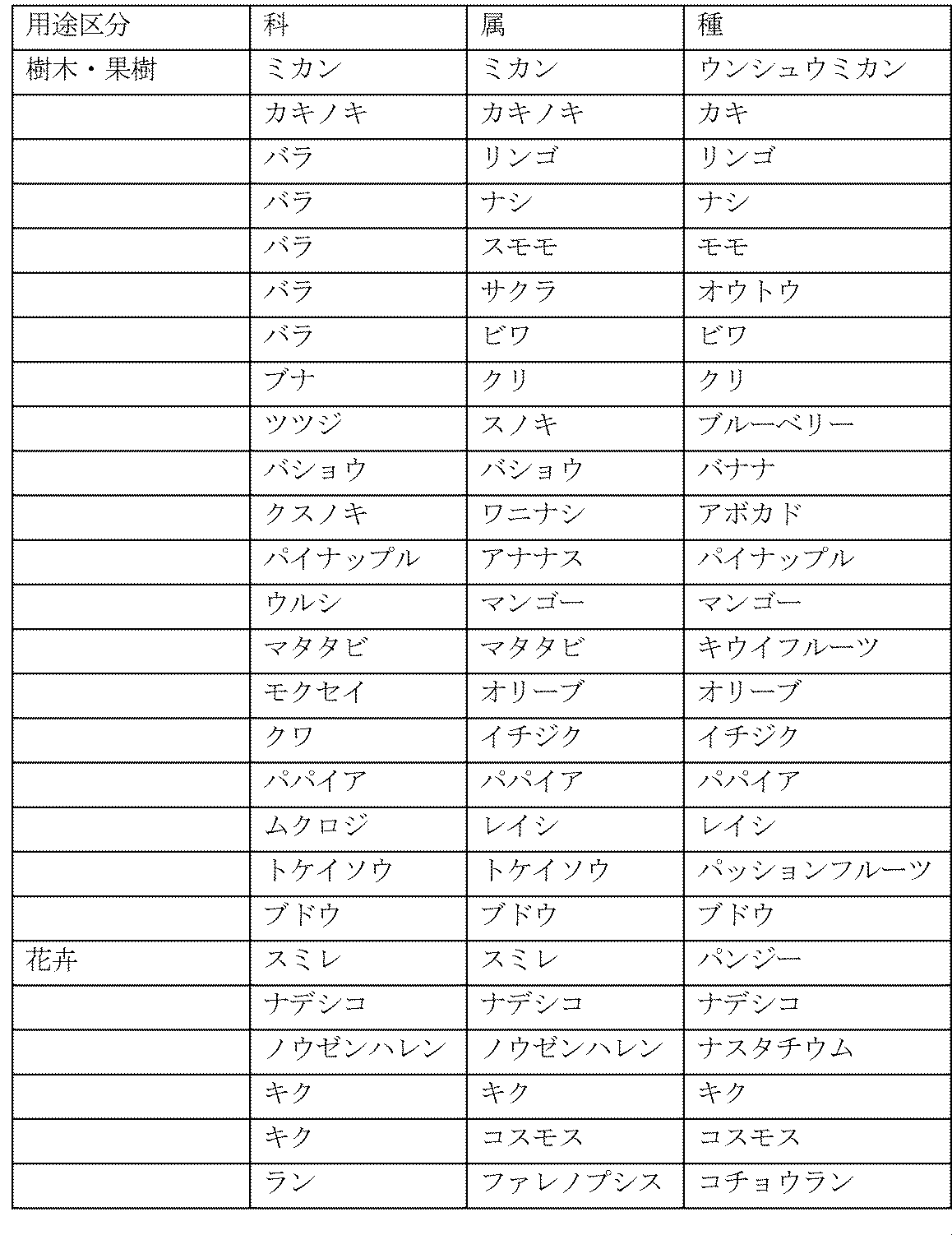

本発明に係る植物総体の栽培方法は、
前述の植物総体の栽培装置を用いる、植物総体の栽培方法であって、少なくとも
液体を貯留する遮光筐体の内面のうち、少なくとも内側面の一部に毛管力を示す内面体を設置し、前記遮光筐体内に前記植物総体の根系を包含できる空間域を形成する工程;
前記空間域を形成する工程の前または後、前記遮光筐体に栽培液体を給水する工程;
遮光筐体内に貯留した栽培液体中で、液相から水分および養分を吸収する根部を生育する工程;および
前記遮光筐体の空間域の内部に存在する水分および酸素中で、気相から酸素を吸収する根部を生育する工程
を含む栽培方法を提供する。
本発明において、「植物総体を育成するのに適した環境」とは、土壌不要としつつ、20~100%RHの湿度を保ち、栽培対象とする植物総体50の根に、主に水分および養分を吸収する「液相根」の領域と、主に酸素を吸収する「気相根」の領域とを、分離して育成できる空間域を意味する。この空間域には、前記遮光筐体11の底面に貯留する栽培液体25由来の水分および、酸素、窒素、二酸化炭素等の気体成分が含まれる。貫通孔16を介し、前記気体成分は遮光筐体11の内外での通気は可能である。また、空間域内の温度は、栽培対象とする植物総体50に適切な温度範囲にあればよく、根系が外気と不完全であるが隔離されているため、急激な温度変化がなく、特別な温度管理機構は必要ではないが、必要に応じて付属させてもよい。
なお、本発明者らが開発したセラミック栽培(特開平10-150871号公報)とは異なり、本発明による植物総体50の栽培方法では、いずれの根部も前記内面体31,32を備えた遮光筐体11の内側面に接して生育することを必要としない。ただし、徒長した根が遮光筐体11の内面に接することは排除しない。
前記植物の育成に要求される養分は、炭素、水素および酸素の他、少なくとも窒素、リン酸、カリウム、カルシウム、マグネシウムおよび硫黄の必須多量元素であり、さらに、鉄、マンガン、ホウ素、亜鉛、モリブデン、銅、塩素、ニッケルの必須微量元素、ケイ素、ナトリウム、コバルトなどの有用元素を包含する。
照光筐体40の天井面に設置された光源41は、遮光筐体11の蓋体15に向けて光を照射することにより、植物総体50を育成する。
照光筐体40は直方体形状に限らず、遮光筐体11に積み重ねることができ形状であることが好ましく、立方体形状の他、例えば、断面半円形、断面台形、断面逆台形、断面三角形、断面六角形の筒形状であってもよい。さらに、照光筐体40の形状は、他の遮光筐体11を積み重ねることができる形状であれば、より一層好ましい。
光源41としては、第1実施形態で使用したものと同一であってもよいが、照光筐体40内の温度上昇を考慮し、第1実施形態で使用したものと同一である必要はなく、異なる光源を組み合わせて使用してもよい。
光源41としては、例えば、LEDランプ、蛍光灯、ハロゲンランプ、ナトリウムランプ、メタルハライドランプ、紫外線ランプ等が挙げられる。
遮光筐体11は、下開き構造の扉14を備えているとともに、蓋体15に3個の貫通孔16を所定のピッチで設けてある。遮光筐体本体12と水位調整手段20とは2つの給水口17,17(図8参照)を介して連通している。
遮光筐体11の上面には照光筐体40が搭載されている。照光筐体40には、接続ホース24を介して水位調整手段20に接続され、かつ、栽培液体25を供給する貯水タンク43を取り付けてある。そして、照光筐体40の天井面には図示しない光源が設置される。
また、前述の実施形態において、温度は、育成対象とする植物総体50にとって適切な温度であって、自然または温度制御装置により、外部から調節される。このため、本発明の栽培装置10に温度制御装置を必ずしも付属させる必要はないが、必要に応じて付属させてもよい。
支持フレーム60は、長方形の底板61の四隅に立設した支柱62の上端部に天板として照光ユニット64を架け渡してある。底板61の外周縁部は曲げ起してリブを形成してある。機械的強度を高めるためである。さらに、隣り合う支柱62には補強板63を架け渡してある。
照光ユニット64は光源として、例えば、LED(図示せず)を内蔵するとともに、制御ユニット65を備えている。そして、照光ユニット64は、その下面に取り付けた散乱板(図示せず)を介し、内蔵するLEDの光を遮光筐体11に照射する。前記散乱板は光を乱反射させることにより、LEDが照射する光の光量を均一化する。
また、内面体31は、遮光筐体11の底面に載置台として設置する場合に限らず、遮光筐体11の底面全面に敷設してもよい。この場合に使用される内面体31は、所望の毛管力だけでなく、植物総体に栽培液体を供給できる保水力を有するものが好ましい。内面体31としては、例えば、紙、不織布、発泡性樹脂、微多孔質体などが挙げられる。微多孔質体の具体例としては、例えば、国際公開番号WO2004/101736に開示されたものが挙げられる。
さらに、内面体31は、遮光筐体11の内側面に立て掛けることにより、斜めに配置してもよい。そして、内面体31を斜めに配置する場合には、蓋体15の貫通孔16は蓋体15の外周縁部に沿って設けておくことが好ましい。前述のように内面体31を配置すれば、例えば、ニンジン、ダイコン、ゴボウなどが栽培しやすくなる。
なお、同一部分には同一番号を付して説明を省略する。
なお、同一部分には同一番号を付して説明を省略する。
天井面に少なくとも一つの貫通孔16を備え、栽培液体25を貯留する遮光筐体11と、遮光筐体11の内面のうち、少なくとも内側面の一部に設置した毛管力を示す内面体31,32と、から構成してある。
遮光筐体11に、栽培液体25の水位を調整する水位調整手段20を接続した構成としてある。
遮光筐体11が、箱形状の遮光筐体本体12と、この遮光筐体本体12の上方開口部を被覆し、かつ、着脱可能な蓋体15とからなる構成としてある。
遮光筐体本体12の開口縁部のうち、対向する開口縁部に架け渡した複数本の吊り下げ具28に、蓋体15を架け渡して吊り下げた構成としてある。
貫通孔16は、スリット形状の長孔であってもよい。
遮光筐体11の側面のうち、少なくとも一つの側面に開閉可能な扉14を設置しておいてもよい。
遮光筐体11の内側面全面に内面体31を設置してもよい。
遮光筐体11の蓋体15の内面のうち、貫通孔16を除く内面に内面体32を設置してもよい。
遮光筐体11の底面全面に、植物総体に栽培液体を供給できる保水力を有する内面体32を敷設してもよい。
遮光筐体11の内面のうち、少なくとも内側面に取り付けた少なくとも1つの保持具26,27を介し、遮光筐体11に内面体32を脱着可能に設置してもよい。
遮光筐体11の内側面に、内面体32を立て掛けて斜めに配置してもよい。
遮光筐体11の底面に、植物総体50を載置する載置台30を設置してもよい。
載置台30を、内面体31,32と同一の素材で形成してもよい。
載置台30を、スノコで構成してもよい。
内面体31,32が、非金属無機質固体材料の焼成物であって、空隙である連通孔を含み、焼成物全体に対する空隙率が10~80%(vol/vol)であり、前記空隙の平均孔径が3μm以下であって、孔径3μm以下の空隙が体積比で全空隙の70%以上であることが好ましい。
遮光筐体11に、前記遮光筐体11の上面に向けて光を照射する光源41を備えた照光筐体40を積み重ねてもよい。
遮光筐体11の上方に、前記遮光筐体11の上面に向けて光を照射する光源を備えた照光ユニット64を配置してもよい。
前述の第1態様ないし第17態様のいずれかに記載された植物総体50の栽培装置10を用いる、植物総体50の栽培方法であって、少なくとも
栽培液体25を貯留する遮光筐体11の内面のうち、少なくとも内側面の一部に毛管力を示す内面体31,32を設置し、前記遮光筐体11内に前記植物総体50の根系を包含できる空間域を形成する工程;
前記空間域を形成する工程の前または後、前記遮光筐体11に栽培液体25を給水する工程;
遮光筐体11内に貯留した栽培液体25中で、液相から水分および養分を吸収する根部を生育する工程;および
前記遮光筐体11の空間域の内部に存在する水分および酸素中で、気相から酸素を吸収する根部を生育する工程
を含む。
第18態様に記載された植物総体50の栽培方法であって、
遮光筐体11の底面に設置した載置台30に、植物総体50を設置して栽培することを特徴とする。
第18態様または第19態様のいずれかに記載された植物総体50の栽培方法であって、
遮光筐体11に貯留する栽培液体25は、水または栽培対象である植物総体50の育成に要求される養分を含んだ養液であって、停滞水であることを特徴とする。
第20態様に記載された植物総体50の栽培方法であって、
養分は、窒素、リン酸、カリウム、カルシウム、マグネシウムおよび硫黄から選択される必須多量元素、鉄、マンガン、ホウ素、亜鉛、モリブデン、銅、塩素、ニッケルから選択される必須微量元素、または、ケイ素、ナトリウム、コバルトなどから選択される有用元素であることを特徴とする。
(1)栽培装置
本発明に係る植物総体としては、根系が肥大する植物を育成対象とする。このため、栽培装置の遮光筐体は、育成する植物を支持し、かつ、肥大した根系を収容することができる形状、大きさおよび重量を有する必要がある。このため、実施例1に係る植物総体の栽培装置は、図9に図示するように、長さ90cm、巾30cm、高さ30.5cmの遮光筐体と、栽培植物に光を照射する光源とで構成されている。
遮光筐体本体を被覆する着脱可能な蓋体は、植物を支持するために、その長さ方向の中心線に沿って巾5cm、長さ66cmの長孔からなる貫通孔を設けた。なお、ジャガイモの茎が伸びて貫通孔を通過した後は、茎が通過した貫通孔の部分を除き、その他の部分は遮光テープで閉鎖した。
なお、実施例1に係る遮光筐体には扉は設けられていない。
遮光筐体の底面のうち、貫通孔の直下に位置する底面に載置台を所定のピッチで3か所に設置した。載置台は、前述の内面体を適宜、寸法調整したものを使用した。
なお、載置台の高さは、必要に応じて内面体の枚数を増やして調節した。
遮光筐体の上面から高さ約35cmの位置に、3本のLEDランプ(6000K(ケルビン))を並設し、7時から19時まで点灯した。なお、当初、室内灯は24時間点灯していたが、試験23日目から7時から19時までの12時間点灯に切り換えた。
蓋体の上面に照射される光量子束密度を計測器(apogee社製、MQ-100)で測定した。測定結果を図10に示す。光量子束密度の単位はμmol/m2/sである。
最大光量子束密度は111(μmol/m2/s)であり、最小光量子束密度は53(μmol/m2/s)であった。
光源に含まれる波長分布を波長分布計測器(Goyalab社製 Gospectro)で計測し、波長分布計測器の計測結果を示すモニターを写真撮影した。撮影結果を図11に示す。横軸は波長(単位:nm)であり、縦軸はエネルギー量を示す分光放射照度(単位:mW/m2/nm)である。
計測結果から、波長451nmであるときに分光放射照度が最大となり、最大分光放射照度は393mW/m2/nmであることが判った。
防カビ対策として薬品処理した3個のジャガイモを載置台にそれぞれ設置した。なお、作業の効率化を図るべく、予め発芽したジャガイモを種イモとした。
種イモ3個が発根するまでは栽培液体として水を使用した。その場合の、栽培液体の水位は遮光筐体の底面に設置した載置台の表面を超え、種イモの下部が少し浸かる位置までとした。
発根後には、栽培液体を養液に変更するとともに、種イモの腐敗を防止すべく、合計2枚の内面体を積み重ねて載置台とした。種イモの下部表面と栽培液体の液面とがほぼ一致するように調整した。養液の成分・濃度はジャガイモの成長度合いに応じて調整した。
本発明において用いる焼成素材からなる内面体の素材には、三河陶器瓦用粘土R2-6を用いた。三河陶器瓦用粘土R2-6の定量分析(あいち産業科学技術総合センターにて実施)の結果を表2に示した。
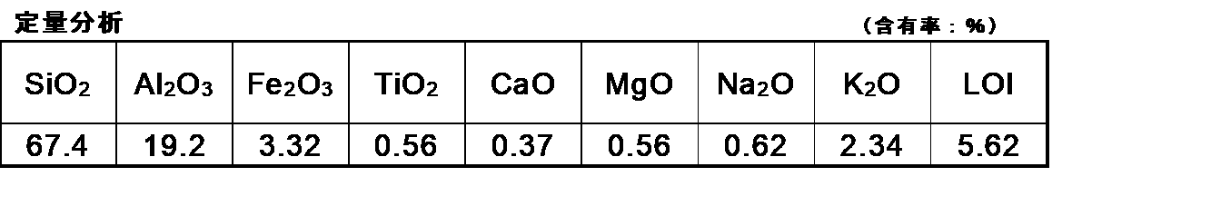
三河焼窯元(有限会社丸俊セラミック)にて、微多孔質焼成素材(陶器瓦用粘土R2-6)を板状に形成し、ガス窯内で焼成温度1090℃×13時間焼き/窯出し30時間の焼成条件下で焼成して、微多孔質焼成体からなる内面体を製造した。内面体の製造条件及び製造した内面体の寸法を表3に示した。また、微多孔質焼成体断面の電子顕微鏡写真を図12に図示した。

(1)対象の微多孔質焼成体サンプルを破砕して、マイクロ遠心チューブ途中で引っかかる寸法のサンプル小片(5~8mm四方、約0.5g)を得る。
(2)サンプル小片を恒量になるまで乾燥し、乾燥重量Wsを測定し、マイクロ遠心チューブ乾燥重量Wtを測定する。
(3)サンプル小片を24時間蒸留水に浸漬する。
(4)サンプル小片を取り出し、ティッシュペーパーで表面に付着した水を軽く拭き取り、サンプル小片の含水重量Wを測定する。含水重量Wからサンプル小片の乾燥重量Wsを差し引いて、サンプル小片の総吸水量W0(=W-Ws)を求める。
(5)このサンプル小片をマイクロ遠心チューブに投入する。このとき、サンプル小片がチューブ途中で引っかかり、底部に接していないことを確認する。
(6)3,000rpmで5分間遠心した後、サンプル小片を取り出し、底部に水が貯留した状態のマイクロ遠心チューブの重量Waを測定する。この重量からマイクロ遠心チューブの重量Wtを差し引いて3,000rpmでの脱水量W3000(=Wa-Wt)を求める。
(7)貯留した水を維持したままのマイクロ遠心チューブに、再度、サンプル小片を投入し、5,500rpmで5分間遠心した後、サンプル小片を取り出し、底部に水が貯留した状態のマイクロ遠心チューブの重量Wbを測定する。この重量から底部に水が貯留した状態のマイクロ遠心チューブの重量Waを差し引いて5,500rpmでの脱水量W5500(=Wb-Wa)を求める。
(8)貯留した水を維持したままのマイクロ遠心チューブに、再度、サンプル小片を投入し、8,000rpmで5分間遠心した後、サンプル小片を取り出し、底部に水が貯留した状態のマイクロ遠心チューブの重量Wcを測定する。この重量から底部に水が貯留した状態のマイクロ遠心チューブの重量Wbを差し引いて8,000rpmでの脱水量W8000(=Wc-Wb)を求める。
(8)貯留した水を維持したままのマイクロ遠心チューブに、再度、サンプル小片を投入し、10,500rpmで5分間遠心した後、サンプル小片を取り出し、底部に水が貯留した状態のマイクロ遠心チューブの重量Wdを測定する。この重量から底部に水が貯留した状態のマイクロ遠心チューブの重量Wcを差し引いて10,500rpmでの脱水量W105000(=Wd-Wc)を求める。
(9)最後に総吸水量W0から脱水された合計量を差し引いて、10,500rpmでの遠心でも脱水されなかった残水量Wr(=W0-Wa-Wb-Wc-Wd)を求める。
(10)9個のサンプル小片について上記測定を行い、各測定値の合計を用いて、対象の微多孔質焼成体サンプルを空隙率および空隙組成を算出した結果を表4に示した。


また、パルプ、糸くずなどの繊維質を板状に押し固めて、内面体を形成することもできる。
室温20℃、湿度50%に設定した屋内に前述の遮光筐体からなる栽培装置を設置し、表13に示すように、2022年11月23日~2023年3月19日までの116日間、栽培した後、子イモを収穫した。
栽培開始から15日目には、図14に示すように、種イモと茎との間で空中に位置する液相根の表面に、綿毛のような多数本の側根が生えていた。綿毛のような側根は、その先端が水中に没していないことから、気相根であると判断できた。水中では液相根が伸長し、地上部は枯れることなく成長していた。
27日目には、貫通孔から地上部が通過し、44日目に着花を確認できた。50日目に着果を確認するとともに、種イモに子イモが着果したことを確認した。
80日目に子イモが種イモを超える大きさまで肥大し、116日目に子イモを収穫した。子イモの重量は163.4g、89.1gであった。
すなわち、本発明によれば、植物の良好な生育に影響すると考えられてきた土壌の団粒構造の環境を、土壌を用いることなく再現することができた。
また、本発明は、土壌を用いないので、栽培終了時には、植物の根部には土壌や藻類などが付着しておらず綺麗な状態であり、煩雑な洗浄作業を行うことなく、そのまま出荷できることが分かった。
(1)栽培装置
実施例2は図15に図示するように、実施例1とほぼ同様な遮光筐体からなる栽培装置を使用した。
遮光筐体の底面のうち、貫通孔の直下に位置する底面に1枚の内面体(厚さ:1.0cm)からなる載置台を所定のピッチで4ヶ所に設置した。載置台は、前述の内面体を適宜、寸法調整したものを使用した。
なお、載置台の高さは、種イモが十分に根を出して成長した後は、前記内面体と同一素材で植木鉢形状に形成した焼成体を逆さまに設置して載置台とし、底上げした。
実施例1と同一のLEDランプ3本を並設し、7時から19時まで12時間、点灯した。なお、室内灯は8から18時まで10時間点灯した。
蓋体の上面に照射される光量子束密度を計測器(apogee社製、MQ-100)で測定した。光量子束密度の単位はμmol/m2/sである。測定結果を図16に示す。
最大光量子束密度は229(μmol/m2/s)であり、最小光量子束密度は134(μmol/m2/s)であった。
光源に含まれる波長分布を波長分布計測器(Goyalab社製 Gospectro)で計測し、波長分布計測器の計測結果を示すモニターを写真撮影した。撮影結果を図17に示す。横軸は波長(単位:nm)であり、縦軸はエネルギー量を示す分光放射照度(単位:mW/m2/nm)である。
計測結果から、波長428nmであるときに分光放射照度が最大となり、最大分光放射照度は198mW/m2/nmであることが判った。
防カビ対策として薬品処理した4個のジャガイモを載置台にそれぞれ設置した。なお、作業の効率化を図るべく、予め発芽したジャガイモを種イモとした。
種イモ4個が発根するまでは栽培液体として水を給水した。栽培液体の水位は遮光筐体の底面に設置した載置台の表面を超え、種イモの下部が少し浸かる深さ(2cm)とした。
発根後には、栽培液体を養液に変更した。そして、十分に発根した後に、種イモの腐敗を防止すべく、内面体と同一素材で植木鉢形状に形成した焼成体をひっくり返して設置し、載置台(高さ:7cm)とした。ただし、液相根は養液に十分に浸かっている状態であった。
なお、養液の成分・濃度はジャガイモの成長度合いに応じて調整した。
実施例2に係る内面体は、実施例1と同一であるので、説明は省略する。
室温20℃、湿度50%に設定した屋内に前述の遮光筐体からなる栽培装置を設置し、表18に示すように、2022年11月8日から栽培を開始した。そして、栽培試験は、2023年4月28日現在においても継続中である。
栽培開始から6日目に発根し、12日目には図19に示すように、種イモから発生した液相根は、その先端部が水中に伸長するとともに、空中に位置する表面には綿毛のような多数の側根が出現していた。綿毛のような側根は、その先端が水中に没していないことから、気相根であると判断できた。22日目には、貫通孔から地上部が通過し、28日目には地上部が遮光筐体の表面に葉を展開した。42日目にストロンが出現し、63日目に貫通孔を遮光テープで閉鎖した。100日目に着花を確認するとともに、子イモが着果していることを確認できた。
(ウコン)
温度22℃、湿度60%に設定した室内に実施例1と同一形状の遮光筐体(RB1型)を設置した。遮光筐体の上方に3本のLEDランプ(6000K(ケルビン))を配置し、14時間点灯して栽培した。
図23に示すように、2023年6月6日にRB1型の遮光筐体の底面に設置したセラミック板に芽出し済みの2個の種ウコンを載置し、蓋体で根部を遮光した。開始日から2日目に発根し、9日目に芽が伸長するとともに、気相根が出現した。21日目に地上部が貫通孔を通過した。43日目に根茎が肥大化を開始し、62日目に新葉が展開した。92日目に形成された根茎部が肥大化し続けた。121日目に収穫した。収穫した2株のウコンのうち、左側の株のウコンは計79.0g、右側の株のウコンは計70.4gであった。
参考のため、図24に21日目の出現した気相根の拡大図を示し、図25に121日目のウコンの根部の拡大図を示す。
(ショウガ)
温度22℃、湿度60%に設定した室内に実施例1と同一形状の遮光筐体(RB1型)を設置した。遮光筐体の上方に3本のLEDランプ(6000K(ケルビン))を配置し、14時間点灯して栽培した。
図26に示すように、2023年5月22日にRB1型の遮光筐体の底面に設置したセラミック板に芽出し済みの種ショウガを載置し、蓋体で根部を遮光した。開始日から8日目に発根し、30日目に液相根が伸長した。31日目に葉が貫通孔を通過し、36日目に気相根が発達した。58日目に新根茎から萌芽した。71日目に茎が伸長し、122日目に新たな根茎が形成された。136日目に収穫した。収穫したショウガは23.9gであった。
参考のため、図27に36日目の発達した気相根の拡大図を示し、図28に136日目の収穫したショウガの拡大図を示す。
(トウモロコシ)
2023年4月26日にポット苗で購入したトウモロコシ苗の根部を水洗いし、土を除去した。一方、温度25℃に設定した研究棟内に設置した栽培ボックス内にRB1型ボックスを設置した。栽培ボックス内は換気扇を備え、照明灯としては高圧ナトリウムランプ(岩崎電気株式会社製 FECサンルクスエース NH360LS)を12時間点灯した。
図29に示すように、5月1日にRB1型ボックスの底面に設置したスノコにクリップを介してトウモロコシ苗を立設した。このとき、トウモロコシ苗の根部の先端は栽培液体に浸かっていた。
開始日から4日目に液相根の伸長と、気相根の発生とを目視で確認した。35日目に雄穂を確認し、42日目に雄穂から花粉を採取した。46日目に雌穂を確認し、49日目に雌穂に人工授粉を行った。穎果が肥大化し、79日目に穎果(えいか)を確認した。
参考のため、図30に4日目の根部の拡大図を示し、図31に79日目のトウモロコシ全体の拡大図を示す。
(ダイズ)
2023年4月26日にポット苗で購入したダイズ苗の根部を水洗いし、土を除去した。一方、温度25℃に設定した研究棟内に設置した栽培ボックス内にRB1型ボックスを設置した。栽培ボックス内は換気扇を備え、照明灯としては高圧ナトリウムランプ(岩崎電気株式会社製 FECサンルクスエース NH360LS)を12時間点灯した。
図32に示すように、5月1日にRB1型ボックスの底面に設置したスノコにクリップを介してダイズ苗を立設した。このとき、ダイズ苗の根部の先端は栽培液体に浸かっていた。
開始日から4日目に液相根の伸長と、気相根の発生とを目視で確認した。21日目に開花して結実した。35日目に開花するとともに、肥大化した。51日目に肥大化が進み、56日目に収穫した。収穫したダイズの総重量は23gであった。
参考のため、図33に4日目の根部の部分拡大図を示し、図34に56日目に収穫したすべてのダイズの拡大図を示す。
(ナタネ)
図35に示すように、温度20.5℃、湿度70%に設定した室内にRB1型ボックスを設置した。そして、RB1型ボックスの底面に配置したセラミック板に、種から発根させたナタネ苗を載置した。ついで、底面から15cmの高さで厚さ4mmの黒色のプラスチック製段ボール2枚を突き合わせて吊り下げることにより、ナタネ苗の茎を支持するとともに、根部を遮蔽した。
照明灯としてはLED(SOLIDLITE社 EL-L01-LT104F-DQM-D2423)を12時間点灯し、2023年6月30日に栽培を開始した。開始日から7日目に気相根が出現した。35日目に下葉が枯れ始め、56日目に茎が2本に分岐していた。77日目に葉が上の棚段に達し、105日目においても葉が側方にも大きくはみ出した。
参考のため、図36および図37に7日目の生長する苗および出現した気相根の拡大図を示す。図38および図39に105日目の成長したナタネおよび根部の拡大図を示す。
(バジル)
図40に示すように、温度20.5℃、湿度70%に設定した室内にRB1型ボックスを設置した。そして、RB1型ボックスの底面に配置したセラミック板に、種から発根したバジル苗を載置した。ついで、底面から15cmの高さで厚さ4mmの黒色のプラスチック製段ボール2枚を突き合わせて吊り下げることにより、バジル苗の茎を支持するとともに、根部を遮蔽した。照明灯としてはLED(SOLIDLITE社 EL-L01-LT104F-DQM-D2423)を12時間点灯し、2023年6月30日に栽培を開始した。
開始日から7日目に気相根が出現した。49日目に花芽が出現し、56日目に花穂が伸長した。67日目に開花し、105日目に種子がほぼ成熟していた。
参考のため、図41に7日目出現した気相根の拡大図を示す。図42、図43および図44に105日目の成長したバジル、収穫した種子および根部の拡大図をそれぞれ示す。
(ハッカ)
図45に示すように、温度20.5℃、湿度70%に設定した室内にRB1型ボックスを設置した。そして、RB1型ボックスの底面に、挿し木で発根させたハッカ苗を直接、載置した。ついで、底面から10cmの高さで厚さ4mmの黒色のプラスチック製段ボール2枚を突き合わせて吊り下げることにより、ハッカ苗の茎を支持するとともに、根部を遮蔽した。照明灯としてはLED(SOLIDLITE社 EL-L01-LT104F-DQM-D2423)を12時間点灯し、2023年8月2日に栽培を開始した。
開始日から7日目に気相根が出現した。28日目に葉腋に花芽が出現し、33日目に開花した。35日目の側枝にも花芽が出現し、49日目にランナーが多数出現した。63日目に実の中で種子が成熟し、70日目に実の成熟が更に進んでいた。
参考のため、図46に7日目に出現した気相根の拡大図を示す。図47および図48に70日目の成長したハッカおよび成熟しつつある種子の拡大図をそれぞれ示す。
(アオシソ)
図49に示すように、温度20.5℃、湿度70%に設定した室内にRB1型ボックスを設置した。そして、RB1型ボックスの底面に配置したセラミック板に、挿し木で発根させたアオシソ苗を載置した。ついで、底面から12cmの高さで厚さ4mmの黒色のプラスチック製段ボール2枚を突き合わせて吊り下げることにより、アオシソ苗の茎を支持するとともに、根部を遮蔽した。照明灯としてはLED(SOLIDLITE社 EL-L01-LT104F-DQM-D2423)を12時間点灯し、2023年7月13日に栽培を開始した。
開始日から7日目に新芽が生長し、14日目に気相根が出現した。21日目に花芽が出現し、腋芽も出現し、27日目に開花した。35日目に開花が進展するとともに、結実した。56日目に実が褐変し、種子を収穫した。
参考のため、図50にアオシソ苗の設置状況を示す拡大図、図51に14日目の出現した気相根の部分拡大図および図52に56日目の根部の拡大図、図53に56日目に収穫した種子の拡大図を示す。
(イチゴ)
図54に示すように、温度20.5℃、湿度70%に設定した室内にRB1型ボックスを設置した。そして、RB1型ボックスの底面に配置したセラミック板に、ランナーの子株を株分けして発根させたイチゴ苗を載置した。ついで、底面から12cmの高さで厚さ4mmの黒色のプラスチック製段ボール2枚を突き合わせて吊り下げることにより、イチゴ苗の茎を支持するとともに、根部を遮蔽した。照明灯としてはLED(SOLIDLITE社 EL-L01-LT104F-DQM-D2423)を12時間点灯し、2023年7月13日に栽培を開始した。
開始日から7日目にランナーが出現し、14日目に気相根が出現した。25日目に花芽が出現し、28日目に開花したので、人工授粉を行った。68日目に肥大化した花托が着色し始めた。70日目に成熟した花托を収穫した。
参考のため、図55に14日目に出現した気相根の部分拡大図、図56に70日目に収穫したイチゴの拡大図を示す。
(カラタチ)
図57に示すように、ポット苗で購入したカラタチ苗の根部を水洗いし、土を除去した。一方、温度22℃、湿度60%に設定した室内に栽培装置として遮光筐体を設置した。遮光筐体としては、貫通孔を丸穴とした点を除き、実施形態1と同一構造を有するもの(これをRB2型という)を使用した。そして、遮光筐体(RB2型)の上方に3本のLEDランプ(6000K(ケルビン))を配置し、14時間点灯して栽培した。
2023年8月31日にRB2型の底面に設置したセラミック板にカラタチの根部を載置し、蓋体で根部を遮光した。開始日から14日目に液相根が伸長し、28日目に新葉が展開した。35日目に液相根が発根し、42日目に気相根が出現した。
参考のため、図58に42日目に出現した気相根の拡大図を示す。
(チャノキ)
図59に示すように、ポット苗で購入したチャノキ苗の根部を水洗いし、土を除去した。一方、温度22℃、湿度60%に設定した室内にRB2型を設置した。RB2型の上方に3本のLEDランプ(6000K(ケルビン))を配置し、14時間点灯して栽培した。
2023年8月31日に、RB2型の底面に設置したセラミック板に、チャノキの根部を載置し、蓋体で根部を遮光した。開始日から14日目に液相根が伸長し、28日目に蕾が肥大すると共に、気相根が出現した。35日目に液相根および気相根が更に発達し、40日目に開花した。
参考のため、図60に35日目の発達した気相根および液相根の拡大図を示し、図61に40日目の開花した花の拡大図を示す。
(パッションフルーツ)
図62に示すように、ポット苗で購入したパッションフルーツ苗の根部を水洗いし、土を除去した。一方、温度22℃、湿度60%に設定した室内にRB2型を設置した。RB2型の上方に3本のLEDランプ(6000K(ケルビン))を配置し、14時間点灯して栽培した。
2023年7月24日にRB2型の底面に設置したセラミック板にパッションフルーツ苗を載置し、蓋体で根部を遮光した。開始日から8日目に液相根の伸長を確認し、25日目に気相根の出現を確認した。59日目に脇芽が伸長し、80日目においても新葉が次々と形成されていることを確認した。今後も栽培を継続する。
参考のため、図63に25日目の出現した気相根の拡大図を示し、図64に73日目の発達した気相根の部分拡大図を示す。
(イチジク)
図65に示すように、ポット苗で購入したイチジク苗の根部を水洗いし、土を除去した。一方、温度22℃、湿度60%に設定した室内にRB2型ボックスを設置した。RB2型ボックスの上方に3本のLEDランプ(6000K(ケルビン))を配置し、14時間点灯して栽培した。
2023年7月24日にRB2型の底面に設置したセラミック板にイチジク苗を載置し、蓋体で根部を遮光した。開始日から8日目に液相根が発生し、30日目に最上位葉の葉面積が拡大し、36日目に気相根が出現した。44日目に新葉が発生し、66日目に液面から発達した気相根が出現し、79日目においても気相根が内面体に張り付いた根から発達していた。
参考のため、図66に36日目に出現した気相根の拡大図を示し、図67に66日目に液面から出現した気相根の拡大図を示す。
(ウラルカンゾウ)
図68に示すように、ポット苗で購入したウラルカンゾウ苗の根部を水洗いし、土を除去した。一方、温度22℃、湿度60%に設定した室内にRB2型を設置した。RB2型の上方に3本のLEDランプ(6000K(ケルビン))を配置し、14時間点灯して栽培した。
2023年7月20日にRB2型の底面に設置したセラミック板にウラルカンゾウ苗を載置し、蓋体で根部を遮光した。開始日から12日目に液相根が伸長し、18日目に気相根が出現した。40日目に直根部が肥大化して伸長した。56日目に萌芽し、82日目に根の最大直径が10mmまで肥大化した。
参考のため、図69に18日目の出現した気相根の拡大図を示し、図70に82日目の肥大化した根部の拡大図を示す。
(ワタ)
図71に示すように、ポット苗で購入したワタ苗の根部を水洗いし、土を除去した。一方、温度22℃、湿度60%に設定した室内にRB2型を設置した。RB2型ボックスの上方に3本のLEDランプ(6000K(ケルビン))を配置し、14時間点灯して栽培した。
2023年8月11日にRB2型の底面に設置したセラミック板にワタ苗を載置し、蓋体で根部を遮光した。開始日から12日目に液相根が伸長するとともに、蕾が出現した。26日目に気相根が液面上に出現し、37日目に第1花が開花した。41日目に第1花が着果し、第2花が開花した。61日目に第1果は肥大中であり、気相根が発達していた。
参考のため、図72に26日目に出現した気相根の拡大図を示し、図73に61日目の発達した気相根の拡大図を示す。
(ミニトマト)
2023年4月19日にポット苗で購入したミニトマト苗の根部を水洗いし、土を除去した。一方、温度25℃に設定した研究棟内に設置した栽培ボックス内にRB2型を設置した。前記栽培ボックス内は換気扇を備え、照明灯としては高圧ナトリウムランプ(岩崎電気株式会社製 FECサンルクスエース NH360LS)を12時間点灯した。
図74に示すように、4月24日にRB2型の底面に設置したセラミック板にミニトマト苗を載置し、栽培を開始した。開始日から9日目に液相根が伸長し、気相根が発生した。16日目に第1花房が開花するとともに、第2花房が出現した。21日目に第1花房が着果し、果実が肥大化した。39日目に第2花房が開花し、着果していた。56日目に第1花房の果実2個を収穫し、重量および糖度を測定した。74日目に第2花房の果実の着色を確認できた。
参考のため、図75に9日目の根部の部分拡大図を示し、図76に74日目のミニトマトの拡大図を示す。
(キュウリ)
図77に示すように、2023年4月19日にポット苗で購入したキュウリ苗の根部を水洗いし、土を除去した。一方、温度25℃に設定した研究棟内に設置した栽培ボックス内にRB2型を設置した。栽培ボックス内は換気扇を備え、照明灯としては高圧ナトリウムランプ(岩崎電気株式会社製 FECサンルクスエース NH360LS)を12時間点灯した。
4月24日にRB2型の底面に設置したセラミック板にキュウリ苗を載置した。このとき、セラミック板の表面は栽培液体の水面とほぼ同等の位置にあり、キュウリ苗の根部の先端部は滞留する栽培液体に浸かっていた。
開始から9日目に液相根の伸長と、気相根の発生とを目視で確認した。16日目に雌花を確認し、21日目に雌花の開花を確認し、28日目に着果を確認した。56日目に1果目(179.3グラム)を収穫し、63日目に2果目(156.2グラム)を収穫し、81日目に3果目を収穫し、107日目に4果目(121.5グラム)を収穫した。栽培開始日から148日目でも5果目が伸長かつ肥大し、液相根および気相根が繁茂していることを確認できた。
参考のため、図78に9日目の根部の拡大図を示し、図79に148日目の根部の部分拡大図を示す。
(ナス)
図80に示すように、2023年4月19日にポット苗で購入したナス苗の根部を水洗いし、土を除去した。一方、温度25℃に設定した研究棟内に設置した栽培ボックス内にRB2型を設置した。栽培ボックス内は換気扇を備え、照明灯としては高圧ナトリウムランプ(岩崎電気株式会社製 FECサンルクスエース NH360LS)を12時間点灯した。
4月24日にRB2型の底面に設置したセラミック板にナス苗を載置した。このとき、セラミック板の表面は栽培液体の水面とほぼ同等の位置にあり、ナス苗の根部の先端部は滞留する栽培液体に浸かっていた。
開始から9日目に液相根の伸長と、気相根の発生とを目視で確認した。25日目にハダニが発生したが、草勢が復活して開花した。140日目に新たに開花するとともに、着果した。154日目に果実が肥大し、158日目にナス2本を収穫した。1本目は143.0gであり、2本目は69.4gであった。
参考のため、図81に9日目の根部の拡大図を示し、図82に140日目の根部の部分拡大図を示す。
(キンレンカ(ナスタチウム))
図83に示すように、温度20.5℃、湿度70%に設定した室内にRB2型を設置した。ただし、RB2型の底面にキンレンカ苗を直接載置した。そして、底面から95mmの高さで厚さ4mmの白色のプラスチック製段ボール2枚を吊り下げてキンレンカ苗の茎を支持した。さらに、プラスチック製ダンボールの表面をアルミホイールで被覆することにより、根部を遮光した。そして、照明灯としてはLED(SOLIDLITE製 EL-L01-LT104F-DQM-D2423)を12時間点灯し、2023年7月25日栽培を開始した。
開始日から27日目に茎が伸長し、62日目に気相根を確認した。72日目に葉が繁茂し、78日目に蕾が出現するとともに、多数の気相根が出現し、80日目に開花した。
参考のため、図84に62日目の気相根の部分拡大図を示し、図85に80日目の開花した状態の拡大図を示す。
(キキョウ)
図86に示すように、温度20.5℃、湿度70%に設定した室内にRB2型を設置した。ただし、RB2型の底面に種から発根したキキョウ苗を直接載置した。そして、底面から95mmの高さで厚さ4mmの白色のプラスチック製段ボール2枚を吊り下げてキキョウ苗の茎を支持した。さらに、プラスチック製ダンボールの表面をアルミホイールで被覆することにより、根部を遮光した。そして、照明灯としてはLED(SOLIDLITE製 EL-L01-LT104F-DQM-D2423)を12時間点灯し、2023年7月25日栽培を開始した。
開始日から52日目に蕾が出現し、62日目に開花するとともに、気相根が栽培液体表面から突出した。根の肥大を促進するために摘花した。69日目に開花し、同様に摘花した。78日目において根の直径が12mmとなった。
参考のため、図87に62日目の気相根の部分拡大図を示し、図88に78日目の根部の拡大図を示す。
(ダイズ)
図89に示すように、温度22℃、湿度60%に設定した室内にRB3型を設置した。RB3型の上方にLEDランプ(共立電照製のHMW95E2SV1A-RM)を配置し、14時間点灯して栽培した。
2023年8月23日にRB3型の底面に設置したセラミック板にダイズを播種し、貫通孔を備えた蓋体で遮蔽した。開始日から1日目に発根し、2日目に幼根が伸長した。6日目に子葉部が緑変し、22日目に子葉が展開し、液相根が伸長した。43日目に本葉が貫通孔を通過した。50日目に花芽が形成されるとともに、気相根が発達した。
参考のため、図90に22日目の液相根の拡大図を示し、図91に50日目の発達した気相根の拡大図を示す。
11 遮光筐体
12 遮光筐体本体
13 開口部
14 扉
15 蓋体
16 貫通孔
17 給水口
20 水位調整手段
21 給水管
22 排水管
23 補給管
24 接続ホース
25 栽培液体
26 保持具(断面T字形)
27 保持具(断面L字形)
28 吊り下げ具
30 載置台(内面体)
31 内面体
32 内面体
40 照光筐体
41 光源
42 位置決め枠体
43 貯水タンク
50 植物総体(栽培植物:ジャガイモ)
51 種イモ
52 茎
53 葉
54 子イモ
60 支持フレーム
61 底板
62 支柱
63 補強板
64 照光ユニット(天板)
65 制御ユニット
Claims (21)
- 天井面に少なくとも一つの貫通孔を備え、栽培液体を貯留する遮光筐体と、
遮光筐体の内面のうち、少なくとも内側面の一部に設置した毛管力を示す内面体と、
からなることを特徴とする植物総体の栽培装置。 - 遮光筐体に、栽培液体の水位を調整する水位調整手段を接続したことを特徴とする請求項1に記載の植物総体の栽培装置。
- 遮光筐体が、箱形状の遮光筐体本体と、この遮光筐体本体の上方開口部を被覆し、かつ、着脱可能な蓋体とからなることを特徴とする請求項1または2に記載の植物総体の栽培装置。
- 遮光筐体本体の開口縁部のうち、対向する開口縁部に架け渡した複数本の吊り下げ具に、蓋体を架け渡して吊り下げたことを特徴とする請求項3に記載の植物総体の栽培装置。
- 貫通孔が、スリット形状の長孔であることを特徴とする請求項1ないし4のいずれかに記載の植物総体の栽培装置。
- 遮光筐体の側面のうち、少なくとも一つの側面に開閉可能な扉を設置したことを特徴とする請求項1ないし5のいずれかに記載の植物総体の栽培装置。
- 遮光筐体の内側面全面に内面体を設置したことを特徴とする請求項1ないし6のいずれかに記載の植物総体の栽培装置。
- 遮光筐体の蓋体の内面のうち、貫通孔を除く内面に内面体を設置したことを特徴とする請求項1ないし7のいずれかに記載の植物総体の栽培装置。
- 遮光筐体の底面全面に、植物総体に栽培液体を供給できる保水力を有する内面体を敷設したことを特徴とする請求項1ないし8のいずれかに記載の植物総体の栽培装置。
- 遮光筐体の内面のうち、少なくとも内側面に取り付けた少なくとも1つの保持具を介し、遮光筐体に内面体を脱着可能に設置したことを特徴とする請求項1ないし9のいずれかに記載の植物総体の栽培装置。
- 遮光筐体の内側面に、内面体を立て掛けて斜めに配置したことを特徴とする請求項1ないし10のいずれかに記載の植物総体の栽培装置。
- 遮光筐体の底面に、植物総体を載置する載置台を設置したことを特徴とする請求項1ないし11のいずれかに記載の植物総体の栽培装置。
- 載置台を、内面体と同一の素材で形成したことを特徴とする請求項12に記載の植物総体の栽培装置。
- 載置台を、スノコで構成したことを特徴とする請求項12に記載の植物総体の栽培装置。
- 内面体が、非金属無機質固体材料の焼成物であって、空隙である連通孔を含み、焼成物全体に対する空隙率が10~80%(vol/vol)であり、前記空隙の平均孔径が3μm以下であって、孔径3μm以下の空隙が体積比で全空隙の70%以上であることを特徴とする請求項1ないし14のいずれかに記載の植物総体の栽培装置。
- 遮光筐体に、前記遮光筐体の上面に向けて光を照射する光源を備えた照光筐体を積み重ねたことを特徴とする請求項1ないし15のいずれかに記載の植物総体の栽培装置。
- 遮光筐体の上方に、前記遮光筐体の上面に向けて光を照射する光源を備えた照光ユニットを配置したことを特徴とする請求項1ないし15のいずれかに記載の植物総体の栽培装置。
- 請求項1ないし17のいずれか1項に記載の植物総体の栽培装置を用いる、植物総体の栽培方法であって、少なくとも
栽培液体を貯留する遮光筐体の内面のうち、少なくとも内側面の一部に毛管力を示す内面体を設置し、前記遮光筐体内に前記植物総体の根系を包含できる空間域を形成する工程;
前記空間域を形成する工程の前または後、前記遮光筐体に栽培液体を給水する工程;
遮光筐体内に貯留した栽培液体中で、液相から水分および養分を吸収する根部を生育する工程;および
前記遮光筐体の空間域の内部に存在する水分および酸素中で、気相から酸素を吸収する根部を生育する工程
を含む、植物総体の栽培方法。 - 遮光筐体の底面に設置した載置台に、植物総体を設置して栽培することを特徴とする請求項18に記載の植物総体の栽培方法。
- 遮光筐体に貯留する栽培液体は、水または栽培対象である植物総体の育成に要求される養分を含んだ養液であって、停滞水であることを特徴する請求項18または19に記載の植物総体の栽培方法。
- 養分は、窒素、リン酸、カリウム、カルシウム、マグネシウムおよび硫黄から選択される必須多量元素、鉄、マンガン、ホウ素、亜鉛、モリブデン、銅、塩素、ニッケルから選択される必須微量元素、または、ケイ素、ナトリウム、コバルトなどから選択される有用元素であることを特徴とする請求項20に記載の植物総体の栽培方法。
Priority Applications (4)
| Application Number | Priority Date | Filing Date | Title |
|---|---|---|---|
| US18/567,110 US20260033445A1 (en) | 2023-04-28 | 2023-10-27 | Culture apparatus and a culture method for a plant whole body |
| CA3228062A CA3228062A1 (en) | 2023-04-28 | 2023-10-27 | APPARATUS AND METHOD OF CULTIVATION FOR A COMPLETE PLANT BODY |
| JP2023571812A JP7514580B1 (ja) | 2023-04-28 | 2023-10-27 | 植物総体の栽培装置および栽培方法 |
| EP23813255.9A EP4477068A4 (en) | 2023-04-28 | 2023-10-27 | CULTIVATION DEVICE AND CULTIVATION METHOD FOR WHOLE PLANT |
Applications Claiming Priority (2)
| Application Number | Priority Date | Filing Date | Title |
|---|---|---|---|
| JP2023-075083 | 2023-04-28 | ||
| JP2023075083 | 2023-04-28 |
Publications (1)
| Publication Number | Publication Date |
|---|---|
| WO2024224663A1 true WO2024224663A1 (ja) | 2024-10-31 |
Family
ID=92538919
Family Applications (1)
| Application Number | Title | Priority Date | Filing Date |
|---|---|---|---|
| PCT/JP2023/038947 Ceased WO2024224663A1 (ja) | 2023-04-28 | 2023-10-27 | 植物総体の栽培装置および栽培方法 |
Country Status (2)
| Country | Link |
|---|---|
| TW (1) | TWI877869B (ja) |
| WO (1) | WO2024224663A1 (ja) |
Citations (6)
| Publication number | Priority date | Publication date | Assignee | Title |
|---|---|---|---|---|
| JPS5026048U (ja) * | 1973-07-06 | 1975-03-25 | ||
| JP3035880U (ja) * | 1996-09-18 | 1997-04-04 | 順三 北條 | 植栽用容器 |
| JPH10150871A (ja) | 1996-09-30 | 1998-06-09 | Haito Karuchiya Kk | 栽培装置およびその製造方法 |
| WO2004101736A1 (ja) | 2003-05-15 | 2004-11-25 | Phytoculture Control Co., Ltd. | 生物培養装置および培養方法 |
| JP2017018004A (ja) * | 2015-07-07 | 2017-01-26 | パナソニックIpマネジメント株式会社 | 水耕栽培装置 |
| WO2019069826A1 (ja) | 2017-10-02 | 2019-04-11 | 株式会社いけうち | 植物栽培装置 |
Family Cites Families (1)
| Publication number | Priority date | Publication date | Assignee | Title |
|---|---|---|---|---|
| JP2014045732A (ja) * | 2012-08-31 | 2014-03-17 | Sharp Corp | 水耕栽培器 |
-
2023
- 2023-10-27 WO PCT/JP2023/038947 patent/WO2024224663A1/ja not_active Ceased
- 2023-10-27 TW TW112141397A patent/TWI877869B/zh active
Patent Citations (6)
| Publication number | Priority date | Publication date | Assignee | Title |
|---|---|---|---|---|
| JPS5026048U (ja) * | 1973-07-06 | 1975-03-25 | ||
| JP3035880U (ja) * | 1996-09-18 | 1997-04-04 | 順三 北條 | 植栽用容器 |
| JPH10150871A (ja) | 1996-09-30 | 1998-06-09 | Haito Karuchiya Kk | 栽培装置およびその製造方法 |
| WO2004101736A1 (ja) | 2003-05-15 | 2004-11-25 | Phytoculture Control Co., Ltd. | 生物培養装置および培養方法 |
| JP2017018004A (ja) * | 2015-07-07 | 2017-01-26 | パナソニックIpマネジメント株式会社 | 水耕栽培装置 |
| WO2019069826A1 (ja) | 2017-10-02 | 2019-04-11 | 株式会社いけうち | 植物栽培装置 |
Also Published As
| Publication number | Publication date |
|---|---|
| TWI877869B (zh) | 2025-03-21 |
| TW202442117A (zh) | 2024-11-01 |
Similar Documents
| Publication | Publication Date | Title |
|---|---|---|
| JP5988981B2 (ja) | 植物の育成方法ならびにそれに用いる育成容器および育成装置 | |
| US20050241231A1 (en) | Methods and devices for promoting the growth of plant air roots | |
| CN208462553U (zh) | 一种利于百合鳞片生根的育苗架 | |
| JP7514580B1 (ja) | 植物総体の栽培装置および栽培方法 | |
| WO2022270130A1 (ja) | 果菜植物の栽培方法 | |
| WO2024224663A1 (ja) | 植物総体の栽培装置および栽培方法 | |
| WO2022210552A1 (ja) | 苗の育苗方法、育苗システム及び苗 | |
| Shiwachi et al. | Mini tuber production using yam (Dioscorea rotundata) vines | |
| CN110447524B (zh) | 一种沙水培培养花生幼苗的方法 | |
| JP7281851B1 (ja) | 植物総体の栽培装置および栽培方法、ならびに栽培装置の製造方法 | |
| CN208129133U (zh) | 一种新型猴樟扦插育苗容器装置 | |
| CN104285537A (zh) | 一种提高水养红云莪术根茎开花率的方法 | |
| CN210328687U (zh) | 一种育苗盘 | |
| CN103355084A (zh) | 一种促进中甸刺玫种子萌发的方法 | |
| JP2008187998A (ja) | スプラウトの栽培方法 | |
| CN115868404B (zh) | 一种抑制发霉的植物种植系统及方法 | |
| JP2021177722A (ja) | 根圏部材及び植物栽培方法 | |
| Yuvaraj et al. | Prospects of aeroponics in agriculture | |
| CN111631053A (zh) | 一种新型农业育种设备 | |
| JP2014045761A (ja) | 根菜類の栽培装置、根菜類の栽培方法 | |
| JP5331609B2 (ja) | 家庭内環境で出来る草花、野菜、ハーブ等の播種・育苗方法 | |
| WO1999063804A1 (en) | Green house and plant cultivation method using it | |
| CN109042276B (zh) | 一种花生芽栽培盘及包括其的花生芽栽培装置 | |
| JP2022159002A (ja) | 苗の育苗方法、育苗システム及び苗 | |
| BRPI0704031A2 (pt) | método de produzir embriões somáticos cotiledonares conìferos |
Legal Events
| Date | Code | Title | Description |
|---|---|---|---|
| WWE | Wipo information: entry into national phase |
Ref document number: 2023571812 Country of ref document: JP |
|
| WWE | Wipo information: entry into national phase |
Ref document number: 18567110 Country of ref document: US |
|
| ENP | Entry into the national phase |
Ref document number: 2023813255 Country of ref document: EP Effective date: 20240829 |
|
| WWE | Wipo information: entry into national phase |
Ref document number: P2024-03023 Country of ref document: AE |
|
| WWE | Wipo information: entry into national phase |
Ref document number: 11202407804Y Country of ref document: SG |
|
| NENP | Non-entry into the national phase |
Ref country code: DE |
|
| WWP | Wipo information: published in national office |
Ref document number: 18567110 Country of ref document: US |