WO2024224896A1 - Élément de limitation d'adhérence, outil de travail, élément de griffe et procédé de limitation d'adhérence - Google Patents
Élément de limitation d'adhérence, outil de travail, élément de griffe et procédé de limitation d'adhérence Download PDFInfo
- Publication number
- WO2024224896A1 WO2024224896A1 PCT/JP2024/011299 JP2024011299W WO2024224896A1 WO 2024224896 A1 WO2024224896 A1 WO 2024224896A1 JP 2024011299 W JP2024011299 W JP 2024011299W WO 2024224896 A1 WO2024224896 A1 WO 2024224896A1
- Authority
- WO
- WIPO (PCT)
- Prior art keywords
- bucket
- adhesion
- plate portion
- adhesion suppression
- work tool
- Prior art date
- Legal status (The legal status is an assumption and is not a legal conclusion. Google has not performed a legal analysis and makes no representation as to the accuracy of the status listed.)
- Ceased
Links
Images












Classifications
-
- E—FIXED CONSTRUCTIONS
- E02—HYDRAULIC ENGINEERING; FOUNDATIONS; SOIL SHIFTING
- E02F—DREDGING; SOIL-SHIFTING
- E02F3/00—Dredgers; Soil-shifting machines
- E02F3/04—Dredgers; Soil-shifting machines mechanically-driven
- E02F3/28—Dredgers; Soil-shifting machines mechanically-driven with digging tools mounted on a dipper- or bucket-arm, i.e. there is either one arm or a pair of arms, e.g. dippers, buckets
- E02F3/36—Component parts
- E02F3/40—Dippers; Buckets ; Grab devices, e.g. manufacturing processes for buckets, form, geometry or material of buckets
-
- B—PERFORMING OPERATIONS; TRANSPORTING
- B08—CLEANING
- B08B—CLEANING IN GENERAL; PREVENTION OF FOULING IN GENERAL
- B08B17/00—Methods preventing fouling
- B08B17/02—Preventing deposition of fouling or of dust
-
- E—FIXED CONSTRUCTIONS
- E02—HYDRAULIC ENGINEERING; FOUNDATIONS; SOIL SHIFTING
- E02F—DREDGING; SOIL-SHIFTING
- E02F3/00—Dredgers; Soil-shifting machines
- E02F3/04—Dredgers; Soil-shifting machines mechanically-driven
- E02F3/28—Dredgers; Soil-shifting machines mechanically-driven with digging tools mounted on a dipper- or bucket-arm, i.e. there is either one arm or a pair of arms, e.g. dippers, buckets
- E02F3/36—Component parts
- E02F3/40—Dippers; Buckets ; Grab devices, e.g. manufacturing processes for buckets, form, geometry or material of buckets
- E02F3/401—Buckets or forks comprising, for example, shock absorbers, supports or load striking scrapers to prevent overload
-
- E—FIXED CONSTRUCTIONS
- E02—HYDRAULIC ENGINEERING; FOUNDATIONS; SOIL SHIFTING
- E02F—DREDGING; SOIL-SHIFTING
- E02F3/00—Dredgers; Soil-shifting machines
- E02F3/04—Dredgers; Soil-shifting machines mechanically-driven
- E02F3/76—Graders, bulldozers, or the like with scraper plates or ploughshare-like elements; Levelling scarifying devices
- E02F3/80—Component parts
- E02F3/815—Blades; Levelling or scarifying tools
-
- E—FIXED CONSTRUCTIONS
- E02—HYDRAULIC ENGINEERING; FOUNDATIONS; SOIL SHIFTING
- E02F—DREDGING; SOIL-SHIFTING
- E02F5/00—Dredgers or soil-shifting machines for special purposes
- E02F5/02—Dredgers or soil-shifting machines for special purposes for digging trenches or ditches
-
- E—FIXED CONSTRUCTIONS
- E02—HYDRAULIC ENGINEERING; FOUNDATIONS; SOIL SHIFTING
- E02F—DREDGING; SOIL-SHIFTING
- E02F7/00—Equipment for conveying or separating excavated material
-
- E—FIXED CONSTRUCTIONS
- E02—HYDRAULIC ENGINEERING; FOUNDATIONS; SOIL SHIFTING
- E02F—DREDGING; SOIL-SHIFTING
- E02F9/00—Component parts of dredgers or soil-shifting machines, not restricted to one of the kinds covered by groups E02F3/00 - E02F7/00
- E02F9/28—Small metalwork for digging elements, e.g. teeth scraper bits
-
- E—FIXED CONSTRUCTIONS
- E21—EARTH OR ROCK DRILLING; MINING
- E21B—EARTH OR ROCK DRILLING; OBTAINING OIL, GAS, WATER, SOLUBLE OR MELTABLE MATERIALS OR A SLURRY OF MINERALS FROM WELLS
- E21B11/00—Other drilling tools
-
- E—FIXED CONSTRUCTIONS
- E21—EARTH OR ROCK DRILLING; MINING
- E21B—EARTH OR ROCK DRILLING; OBTAINING OIL, GAS, WATER, SOLUBLE OR MELTABLE MATERIALS OR A SLURRY OF MINERALS FROM WELLS
- E21B11/00—Other drilling tools
- E21B11/04—Boring grabs
Definitions
- This disclosure relates to adhesion prevention members, work tools, claw members, and adhesion prevention methods, and in particular to technology suitable for construction machinery that processes work objects such as soil and mud.
- excavation work is carried out using construction machinery such as backhoes, wheel loaders, earth augers, earth drills, bulldozers, horizontal multi-axis excavators, and power blenders.
- construction machinery such as backhoes, wheel loaders, earth augers, earth drills, bulldozers, horizontal multi-axis excavators, and power blenders.
- backhoe if soil material, including wet clay, adheres to and accumulates on the inner surface of the bucket during excavation work, the effective capacity of the bucket decreases, which causes a decrease in work efficiency.
- bucket swings and impacts pose issues such as generating loud noise and vibrations, and construction work must be carried out with consideration for the surrounding environment.
- the accumulated swinging and impacts of the bucket can cause fatigue in the connectors at the bucket connection points and the bucket tip, requiring the trouble of replacing them at regular intervals.
- a decrease in work efficiency due to soil adhering to the bucket also occurs in the automated driving systems for construction machinery, which have been put into practical use in recent years. It is difficult for the system to keep track of the soil adhering to the bucket during automated driving, and it is also difficult to intentionally swing the bucket using automatic control. For this reason, if automated driving continues for a certain period of time or longer, the automated driving must be stopped and the inside of the bucket cleaned. However, cleaning the bucket requires an operator to approach the construction machinery, which poses the issue of not being able to fully ensure safety, as the operator may come into contact with other construction machinery that is operating automatically.
- Patent Document 1 Technology for preventing soil from adhering to the inside of a bucket is disclosed, for example, in Patent Document 1.
- a water-repellent coating or lining is applied to the entire inner surface of the bucket.
- buckets have curved parts and welded bead parts. For this reason, it is practically difficult to attach and process a lining or coating to adhere to the entire inner surface of the bucket, as in the technology described in Patent Document 1. Furthermore, in a configuration in which a lining or coating is provided on the entire inner surface of the bucket, if the lining or coating is damaged by an impact during excavation, it is difficult to partially repair only the damaged area. For this reason, with the technology described in Patent Document 1, there is a problem in that the bucket needs to be removed from the construction machine when performing repair work, and excavation must be suspended for a long period of time. In other words, for construction machines, it is desirable to provide an adhesion prevention member that is easy to attach and repair while effectively preventing the work object from adhering to the working tool.
- the technology disclosed herein has been developed in consideration of the above circumstances, and aims to effectively prevent the work object from adhering to the work tool while improving the ease of installation and repair.
- the adhesion suppression member (10) of the present disclosure is An adhesion suppression member (10) for suppressing adhesion of a work object to a work tool (20, 20', 30, 40, 50, 60, 70, 80) of a construction machine (100, 200, 300, 400, 500, 600, 700), comprising:
- the work tool is formed in a plate shape having a water-repellent resin material (12) on its surface, and is installed on a predetermined portion of the work tool (20, 20', 30, 40, 50, 60, 70, 80) so that the surface forms a part of the surface of the work tool (20, 20', 30, 40, 50, 60, 70, 80) that contacts the work object.
- the adhesion suppression member (10) includes: The device further comprises a plate-shaped metal material (11) that is joined to a surface of the resin material (12) opposite to the surface of the resin material (12) and fixed to the predetermined portion.
- the working tool (20, 20') of the present disclosure is a working tool (20, 20') including an adhesion suppression member (10),
- the construction machine is a backhoe (100)
- the working tool (20, 20') is a bucket (20, 20') that is rotatably attached to the tip of the arm (142) of the backhoe (100) and has a bottom plate portion (21) and side plate portions (22, 23) that form a storage portion (28) for storing the excavated work object
- the adhesion suppression member (10) is provided on either or both of the bottom plate portion (21) and the side plate portions (22, 23).
- a work tool (20') includes:
- the bucket (20') is a skeleton bucket (20') having a plurality of meshes (27) on the bottom plate portion (21),
- the adhesion suppression member (10) is provided on either or both of a portion of the bottom plate portion (21) where the meshes (27) are not provided and the side plate portions (22, 23).
- a work tool (20) includes: The adhesion suppression member (10) is formed in a rectangular plate shape, A plurality of the adhesion suppression members (10) are arranged in parallel on the bottom plate portion (21) such that their longitudinal directions are substantially parallel to the direction of the rotation axis (R) of the bucket (20).
- a work tool (20) includes: The bottom plate portion (21) has a flat surface portion (21A) extending from an opening side of the storage portion (28) and a curved surface portion (21B) curved so as to be convex toward the outside of the storage portion (28) from an end portion of the flat surface portion (21A) opposite to the opening side, A plurality of the adhesion suppression members (10) are provided on the flat surface portion (21A) and at least on a portion of the curved surface portion (21B) on the flat surface portion (21A) side.
- a work tool (20) includes: The bucket (20) includes an edge plate portion (24) joined to an end portion of the bottom plate portion (21) and forming a part of an opening edge of the storage portion (28),
- the adhesion suppression member (10) is provided on at least one or all of the bottom plate portion (21), the side plate portions (22, 23) and the edge plate portion (24).
- a work tool (20) includes: The bucket (20) further includes a claw portion (5A to 5E) attached to a tip of the edge plate portion (24) via an adapter (4A to 4E), The adhesion suppression member (10) is installed on at least one or all of the bottom plate portion (21), the side plate portions (22, 23), the edge plate portion (24), and the claw portions (5A to 5E).
- the bucket (20) is further provided with a vibration generating device (8A) capable of transmitting vibration to the bucket (20).
- a working tool (30) is a working tool (30) including an adhesion suppression member (10),
- the construction machine is a wheel loader (200)
- the working implement is a bucket (30) that is rotatably attached to the tip of a boom (231) of the wheel loader (200) and has a bottom plate portion (31) and side plate portions (32, 33) that form a storage portion (38) that stores the work object
- the adhesion suppression member (10) is provided on either or both of the bottom plate portion (31) and the side plate portions (32, 33).
- a working tool (40) is a working tool (40) including an adhesion suppression member (10),
- the construction machine is a bulldozer (300),
- the working implement is a blade (40) that is attached to the tip of a support frame (331, 332) of the bulldozer (300) and pushes out the work object;
- the adhesion suppression member (10) is disposed on the front surface of the blade (40).
- a working tool (50) is a working tool (50) including an adhesion suppression member (10),
- the construction machine is an earth drill excavator (400) used in an earth drill method for pile construction
- the working tool is a drilling bucket (50) that is attached to the tip of a kelly bar (450) provided on the earth drill excavator (400) and takes in and discharges excavated soil as the work object
- the drilling bucket (50) includes a cylindrical bucket body (51) and a bottom cover (52) capable of closing a lower end opening of the bucket body,
- the adhesion suppression member (10) is provided on either or both of the inner peripheral surface of the bucket body (51) and the inner surface of the bottom cover (52).
- a working tool (60) is a working tool (60) including an adhesion suppression member (10),
- the construction machine is an all-casing excavator (500) used in the all-casing method of pile construction,
- the working tool is a hammer grab (60) that is suspended by a lifting device (530) provided on the all-casing excavator (500) and grabs and discharges excavated soil as the work object,
- the hammer grabber (60) includes a hammer grabber body (61) and a pair of shells (63, 64) attached to a lower end of the hammer grabber body (61) so as to be freely opened and closed.
- the adhesion suppression member (10) is disposed on the inner circumferential surfaces of the pair of shells (63, 64).
- a working tool (70) is a working tool (70) including an adhesion suppression member (10),
- the construction machine is a horizontal multi-axis excavator (600) used in a diaphragm wall construction method
- the working implement is a pair of rotary cutters (70, 70) that are arranged side by side at the lower end of an excavator body (620, 621) of the horizontal multi-axis excavator (600) and excavate the ground by being driven in rotation;
- the rotary cutter (70, 70) includes a cylindrical rotating drum (71) and a plurality of blades (72) that are provided on the outer circumferential surface of the rotating drum (71) and protrude in the radial direction and have cutter bits (74) fixed to their tips.
- the adhesion suppression member (10) is provided on the surfaces of a plurality of the blades (72).
- a working tool (80) is a working tool (80) including an adhesion suppression member (10),
- the construction machine is a ground improvement device (700) used in a power blender method,
- the working tool is a trencher type agitation mixer (80) provided in the ground improvement device (700),
- the trencher type stirring mixer (81) includes a columnar frame (81), sprockets (82, 83) provided at the upper and lower ends of the frame (81), an endless chain (84) wound around the sprockets (82, 83), and a plurality of stirring blades (88) provided on the outer periphery of the endless chain (84),
- the adhesion suppression member (10) is provided on either or both of the surface of the frame (81) and the surface of the stirring blade (88).
- the claw member (5F) of the present disclosure is a claw member (5F) attached to a working tool (20),
- the claw body (5G) includes a flat portion (5H) formed with a length substantially equal to the opening width of the bucket (20), and the claw body (5G) is attached to the tip of the edge plate portion (24) via an adapter (4A-4E), and the adhesion suppression member (10) is installed on the flat portion (5H).
- the adhesion suppression method of the present disclosure is an adhesion suppression method using an adhesion suppression member (10),
- the adhesion prevention member (10) is installed on the specified portion of the working tool (20, 20', 30, 40, 50, 60, 70, 80) so that the surface of the adhesion prevention member (10) forms part of a surface of the working tool (20, 20', 30, 40, 50, 60, 70, 80) that contacts the work object.
- the technology disclosed herein can effectively prevent the workpiece from adhering to the tool while improving ease of installation and repair.
- FIG. 1 is a schematic side view showing a construction machine of a first embodiment.
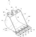
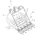
- FIG. 2 is a schematic perspective view showing a bucket according to the first embodiment.
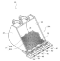
- FIG. 4 is a perspective view showing soil adhering to the inner surface of a bucket.
- 1A is a schematic perspective view showing an adhesion suppression member according to an embodiment of the present invention
- FIG. 1B is a cross-sectional view taken along line AA of FIG.
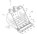
- FIG. 13 is a schematic perspective view illustrating an example in which an adhesion prevention member is provided on the inner surface of a bucket.
- FIG. 13 is a schematic diagram illustrating the attachment pattern of the adhesion suppression member in Demonstration Test 1.
- FIG. 1 is a schematic diagram illustrating the results of demonstration test 1.
- FIG. 13 is a schematic diagram illustrating the attachment pattern of the adhesion suppression member in Demonstration Test 2.
- FIG. 13 is a schematic diagram illustrating the results of demonstration test 2.
- FIG. 13 is a schematic diagram illustrating the attachment pattern of the adhesion suppression member in Demonstration Test 3.
- FIG. 13 is a schematic diagram illustrating the results of demonstration test 3.
- FIG. 1 is a schematic diagram illustrating the results of a noise test.
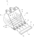
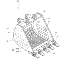
- FIG. 2 is a schematic perspective view showing a bucket of a first modified example according to the first embodiment.
- FIG. 11 is a schematic perspective view showing a bucket of Modification 2 according to the first embodiment.
- FIG. 11 is a schematic perspective view showing a bucket of a modified example 3 according to the first embodiment.
- FIG. 13 is a schematic perspective view showing a bucket of Modification 4 according to the first embodiment.
- FIG. 11 is a schematic side view showing a construction machine according to a second embodiment.
- FIG. 11 is a schematic perspective view showing a bucket according to a second embodiment.
- FIG. 11 is a schematic side view showing a construction machine according to a third embodiment.
- FIG. 11 is a schematic perspective view showing a blade according to a third embodiment.
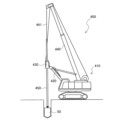
- FIG. 13 is a schematic side view showing a construction machine according to a fourth embodiment.
- FIG. 11 is a schematic side view showing a drilling bucket according to a fourth embodiment.
- FIG. 11 is a schematic vertical cross-sectional view showing a drilling bucket according to a fourth embodiment.
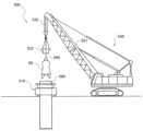
- FIG. 13 is a schematic side view showing a construction machine according to a fifth embodiment.
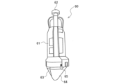
- FIG. 13 is a schematic perspective view showing a state in which the hammer grab according to the fifth embodiment is closed.
- FIG. 13 is a schematic perspective view showing a state in which the hammer grab according to the fifth embodiment is open.
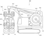
- FIG. 13 is a schematic side view showing a construction machine according to a sixth embodiment.
- FIG. 13 is a schematic view of a rotary cutter according to a sixth embodiment, as viewed from the rotation axis direction.
- FIG. 13 is a schematic view of a rotary cutter according to a sixth embodiment, viewed from a radial direction.
- FIG. 13 is a schematic side view showing a construction machine according to a seventh embodiment.
- FIG. 13 is a schematic perspective view showing a trencher type stirring mixer according to a seventh embodiment.
- FIG. 13 is a schematic plan view of a modified example according to the seventh embodiment.
- FIG. 13 is a schematic side view of a modified example according to the seventh embodiment.
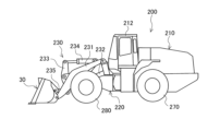
- FIG. 1 is a schematic side view showing a construction machine of a first embodiment.
- the construction machine is, for example, a backhoe 100 (hydraulic excavator) equipped with a bucket 20 as a working tool.
- the construction machine is not limited to the backhoe 100, and may be, for example, a wheel loader, etc., as long as it is a construction machine equipped with a bucket.
- the construction machine may also be a dozer, grader, etc. equipped with a blade as a working tool.
- the construction machine will be described using the backhoe 100 as an example.
- the backhoe 100 comprises a lower running body 110, a rotating device 120, an upper rotating body 130, and a work machine 140.
- the lower running body 110 has a crawler 112 and a drive unit (not shown).
- the backhoe 100 travels by driving the crawler 112 with power transmitted from the drive unit.
- the upper rotating body 130 is supported on the lower running body 110 via the rotating device 120.
- the upper rotating body 130 is driven to rotate by the rotating device 120 being operated by power from a hydraulic motor (not shown).
- the upper rotating body 130 is provided with a cabin 131.
- An operator who operates the backhoe 100 rides in the cabin 131.
- the backhoe 100 may be operated by remote control or by automatic driving control. In this case, the backhoe 100 does not need to be provided with the cabin 131.
- the work machine 140 includes a boom 141, an arm 142, a bucket link 143, a bucket 20 as a work tool, and multiple cylinders 150, 151, and 152.
- the base end of the boom 141 is rotatably supported on the upper rotating body 130.
- the base end of the arm 142 is rotatably supported on the tip side of the boom 141.
- the bucket 20 is rotatably supported on the tip side of the arm 142.
- the bucket link 143 connects the arm 142 and the bucket 20.
- the boom cylinder 150 is connected to the upper rotating body 130 and the boom 141. When the boom cylinder 150 extends or retracts, the boom 141 rotates relative to the upper rotating body 130.
- the arm cylinder 151 is connected to the boom 141 and the arm 142. When the arm cylinder 151 extends or retracts, the arm 142 rotates relative to the boom 141.
- the bucket cylinder 152 is connected to the arm 142 and the bucket link 143. When the bucket cylinder 152 extends or retracts, the bucket 20 rotates relative to the arm 142. Note that an auxiliary attachment such as a tilt rotator that rotates the bucket 20 around the axis of the arm 142 may be interposed between the bucket 20 and the arm 142.
- FIG. 2 is a schematic perspective view showing the bucket 20 according to the first embodiment.
- the direction of the rotation axis R of the bucket 20 may be referred to as the "left-right direction" or the "width direction”.
- the bucket 20 is shown as a so-called standard bucket, but it may also be a narrow bucket or a wide bucket.
- the bucket 20 may be another type of bucket, such as a slope bucket, a multi-purpose bucket, a material handling bucket, or a grab bucket.
- the bucket 20 is made of, for example, steel, and includes a bucket body 20A, multiple adapters 4A-4E, multiple claws 5A-5E, and a pair of brackets 6L, 6R.
- the bucket body 20A has a bottom plate 21, a left side plate 22, a right side plate 23, an edge plate 24, and a bracket fixing plate 25.
- the bottom plate 21 and the side plates 22, 23 form a storage section 28 for storing work objects such as excavated soil and mud.
- the bottom plate portion 21 has a flat surface portion 21A extending from the opening side of the storage portion 28 in a substantially flat shape, and a curved surface portion 21B curved so as to be convex from the end of the flat surface portion 21A toward the outside of the storage portion 28.
- the flat surface portion 21A and the curved surface portion 21B may be a single plate material, or may be formed by joining separate plate materials by welding or the like.
- the edge plate portion 24 is fixed by welding to the end of the flat surface portion 21A opposite the curved surface portion 21B.
- the bracket fixing plate portion 25 is fixed by welding to the end of the curved surface portion 21B opposite the flat surface portion 21A.
- the left side plate portion 22 is fixed by welding to the left end of the bottom plate portion 21, the edge plate portion 24, and the bracket fixing plate portion 25.
- the right side plate portion 23 is fixed by welding to the right end of the bottom plate portion 21, the edge plate portion 24, and the bracket fixing plate portion 25.
- a number of adapters 4A-4E are fixed to the edge plate portion 24 at a predetermined interval in the left-right direction.
- a number of claw portions 5A-5E are removably attached to the adapters 4A-4E.
- the claw portions 5A-5E are shown as flat claws, but they may also be excavation claws that become thinner toward the tip.
- the pair of brackets 6L, 6R are provided on the outer surface of the bracket fixing plate portion 25 opposite the housing portion 28, and face each other at a predetermined distance in the left-right direction.
- a pair of insertion holes 6A, 6B are provided in each of the brackets 6L, 6R.
- a pin (not shown) for connecting the bucket main body portion 20A to the arm 142 (see FIG. 1) is inserted into the insertion hole 6A on the opening side.
- a pin (not shown) for connecting the bucket main body portion 20A to the bucket link 143 (see FIG. 1) is inserted into the insertion hole 6B on the rear side.
- the bucket 20 is excavating soil material such as soil and sand containing wet clay.
- Wet soil material has the tendency to easily adhere to the inner surface of the bucket 20, which is made of steel.
- such wet soil material tends to adhere to (1) the edge plate portion 24 of the bucket body 20A, (2) the flat surface portion 21A of the bottom plate portion 21 and the part of the curved surface portion 21B on the flat surface portion 21A side, and (3) the edge plate portion 24 side and the flat surface portion 21A side of the side plate portions 22, 23.
- the claws 5A to 5E are flat-claw types, soil also tends to adhere to the spaces between the claws 5A to 5E.
- an adhesion suppression member 10 shown in FIG. 4 is installed on the inner surface of the bucket 20 to suppress soil from adhering to the inner surface of the bucket 20. Details of the adhesion suppression member 10 are described below.
- Fig. 4A is a schematic perspective view showing the adhesion suppression member 10 according to the present embodiment, and Fig. 4B is a cross-sectional view taken along line AA of (A).
- the adhesion suppression member 10 has a rectangular strip shape (rectangular plate shape) overall, and has a two-layer structure in which a lower layer of metal material 11 is bonded to an upper layer of resin material 12.
- the direction in which the long side of the adhesion suppression member 10 extends is referred to as the longitudinal direction X
- the direction in which the short side extends is referred to as the transverse direction Y.
- the metal material 11 is, for example, a plate-shaped steel material, and in this embodiment, is formed of stainless steel with excellent corrosion resistance.
- the metal material 11 may be formed using carbon steel, tool steel, or the like.
- the length W1 (see FIG. 4(B)) of the metal material 11 in the short-side direction Y is not particularly limited, but in this embodiment, it is about 90 to 110 mm, preferably about 105 mm.
- the length L1 (see FIG. 4(A)) of the metal material 11 in the long-side direction X may be an appropriate length according to the width of the bucket 20, for example, 500 to 2000 mm.
- the thickness T1 (see FIG.
- the thickness T1 of the metal material 11 is about 0.1 to 1 mm, preferably about 0.5 mm.
- the resin material 12 is, for example, a plate-shaped fluororesin material, and in this embodiment, is made of polytetrafluoroethylene (hereinafter, PTFE).
- PTFE polytetrafluoroethylene
- PTFE has very low surface free energy (surface tension), excellent water repellency and oil repellency, and can effectively suppress the adhesion of soil.
- the resin material 12 is not limited to PTFE, and for example, PFA (perfluoroalkoxyalkane), FEP (perfluoroethylenepropene copolymer), ETFE (ethylenetetrafluoroethylene copolymer), PVDF (polyvinylidene fluoride/vinylidene fluoride/polyvinylidene fluoride), etc. can be used.
- the length W2 (see FIG. 4(B)) of the resin material 12 in the short direction Y is not particularly limited, but in this embodiment it is about 90 to 105 mm, and preferably about 100 mm.
- the length L2 (see FIG. 4(A)) of the resin material 12 in the long direction X may be an appropriate length according to the width of the bucket 20, similar to the length L1 of the metal material 11.
- the thickness T2 (see FIG. 4(B)) of the resin material 12 is not particularly limited, but in this embodiment it is about 0.1 to 1 mm, and preferably about 0.5 mm.
- the fluororesin used in the resin material 12 is a difficult-to-join material, and it is difficult to simply join the resin material 12 and the metal material 11.
- the joining method disclosed in JP 2022-049070 A can be used to join the resin material 12 and the metal material 11.
- the outline of the joining method will be briefly described below.
- Step (2) The metal material 11 on which the metal oxide particle clusters are formed is brought into contact with the resin material 12 to form a joining interface.
- Step (3) The interface to be joined is heated by irradiating it with a laser beam, and the metal material 11 and the resin material 12 are brought into close contact with each other using a roller, thereby applying pressure to the interface to be joined.
- the adhesion suppression member 10 manufactured by the above steps (1) to (3) has a high bond strength between the resin material 12 and the metal material 11, and can withstand shocks and the like during excavation without peeling off from each other.
- the method of joining the metal material 11 and the resin material 12 is not limited to the above-mentioned steps (1) to (3), and other well-known methods can also be used.
- the surface of the metal material 11 opposite the interface to be joined is referred to as the "rear surface” of the adhesion suppression member 10
- the surface of the resin material 12 opposite the interface to be joined is referred to as the "front surface” of the adhesion suppression member 10.
- FIG. 5 is a schematic perspective view illustrating an example in which the adhesion prevention member 10 of the first embodiment is installed on the inner surface of the bucket 20.
- the adhesion prevention member 10 may be attached to the inner surface of the bucket 20 with double-sided tape applied to the back surface (preferably the entire back surface), or may be adhered to the inner surface of the bucket 20 with an adhesive applied to the back surface. If double-sided tape is used, adhesive marks are less likely to remain when replacing the adhesion prevention member 10 with a new one, making the replacement work easier. There are no particular restrictions on the type of double-sided tape, but it is preferable to use a double-sided tape for outdoor use that has strong adhesive power.
- the method of installing the adhesion suppression member 10 is not limited to the method using double-sided tape or adhesive.
- the edge E (see FIG. 4(B)) of the metal material 11 that protrudes beyond the resin material 12 may be fixed to the inner surface of the bucket 20 by spot welding, or predetermined locations of the adhesion suppression member 10 may be fixed using rivets or bolts.
- the adhesion suppression member 10 will be described as being attached using double-sided tape.
- multiple adhesion prevention members 10 are installed on the inner surface of the bucket 20 in areas where work objects such as soil and mud containing wet clay tend to adhere (see grey area in Figure 3). Specifically, the adhesion prevention members 10 are attached to (1) the edge plate portion 24, (2) the flat surface portion 21A of the bottom plate portion 21 and the flat surface portion 21A side portion of the curved surface portion 21B, and (3) the flat surface portion 21A side portions of the side plate portions 22 and 23.
- the adhesion suppression member 10 on the edge plate portion 24 and the bottom plate portion 21 is attached so that its longitudinal direction is approximately parallel to the direction of the rotation axis R of the bucket 20.
- a welded bead BD is present at the boundary between the edge plate portion 24 and the bottom plate portion 21, and if the adhesion suppression member 10 interferes with the bead BD, the adhesion suppression member 10 will be easily peeled off due to impacts during excavation work, etc. For this reason, the adhesion suppression member 10 is attached near the boundary between the edge plate portion 24 and the bottom plate portion 21 in a manner that removes the bead BD.
- the adhesion suppression member 10 is attached to the curved surface portion 21B after first bending and plastically deforming the adhesion suppression member 10 to fit the curved surface portion 21B. By bending and attaching the adhesion suppression member 10, the adhesive strength of the adhesion suppression member 10 to the curved surface portion 21B can be improved.
- one adhesion suppression member 10 is attached to the edge plate portion 24 and a total of four adhesion suppression members 10 are attached to the bottom plate portion 21, but the number of adhesion suppression members 10 is not limited to this, and an appropriate number of adhesion suppression members can be attached depending on the specific dimensions of the edge plate portion 24 and the bottom plate portion 21.
- the adhesion suppression members 10 on the side plate portions 22, 23 are attached so that their longitudinal direction is approximately parallel to the surface direction of the flat surface portion 21A.
- the adhesion suppression members 10 need only be attached to at least the portions on the flat surface portion 21A side.
- three adhesion suppression members 10 are attached to each of the left side plate portion 22 and the right side plate portion 23, but the number of adhesion suppression members 10 is not limited to this, and an appropriate number of adhesion suppression members 10 may be attached depending on the specific dimensions of the side plate portions 22, 23.
- adhesion suppression members 10 may be attached in a spread pattern, but if the ends of adjacent adhesion suppression members 10 are in contact with each other, the ends of the adhesion suppression members 10 may interfere with each other due to shocks, vibrations, etc., during excavation work, and may become more likely to peel off. For this reason, it is preferable to attach multiple adhesion suppression members 10 with a predetermined clearance C between them.
- the specific value of clearance C is not particularly limited, but the narrower the clearance C, the greater the effect of suppressing soil adhesion. In this embodiment, clearance C is set to 20 to 90 mm, preferably 30 mm.
- the claws 5A to 5E attached to the bucket 20 are of the so-called flat-claw type.
- soil tends to adhere to the spaces between the claws 5A to 5E.
- adhesion suppression members 10 it is preferable to attach adhesion suppression members 10 to the claws 5A to 5E as well.
- the resin material 12 forming the surface of the adhesion suppression member 10 has a small surface free energy, so that the excavated soil contained in the bucket 20 is less likely to adhere to the surface of the adhesion suppression member 10.
- the metal material 11 and the resin material 12 of the adhesion suppression member 10 are thin and easily deformable, it can be attached in close contact with the curved surface portion 21B of the bottom plate portion 21. Furthermore, the adhesion suppression member 10 is in the shape of a strip, and can be attached by removing the bead BD at the boundary between the edge plate portion 24 and the bottom plate portion 21. In other words, it is possible to reliably improve the adhesion of the adhesion suppression member 10 to the bucket 20 while also effectively improving the ease of installation.
- the multiple adhesion suppression members 10 are each independently attached to the inner surface of the bucket 20. Therefore, if some of the adhesion suppression members 10 are damaged due to impact during excavation or deteriorated due to long-term use, only the damaged or deteriorated adhesion suppression members 10 need to be replaced. In other words, the replacement work can be performed while the bucket 20 is still attached to the backhoe 100, which reliably improves repairability. Furthermore, because the replacement work can be performed in a short time, it is possible to minimize the impact on excavation work and construction time.
- FIG. 6 is a schematic diagram for explaining the attachment pattern of the adhesion inhibiting member 10 in demonstration test 1. In the figure, the adhesion inhibiting member 10 is shown by hatching. The adhesion inhibiting member 10 was attached to the inner surface of the bucket using double-sided tape.
- one adhesion suppression member 10 was attached to the edge plate portion so that its longitudinal direction was approximately parallel to the rotation axis direction of the bucket.
- a total of five adhesion suppression members 10 were attached in parallel to the flat and curved surfaces of the bottom plate portion so that their longitudinal direction was approximately parallel to the rotation axis direction of the bucket.
- the clearance between each adhesion suppression member 10 was set to approximately 30 mm.
- the value obtained by dividing the sum of the surface areas of each adhesion suppression member 10 by the surface area of the inner surface of the bucket (hereinafter referred to as the PTFE area ratio) was approximately 36%.
- pattern (B1) a total of four adhesion suppression members 10 are attached in parallel to the bottom plate so that their longitudinal direction is approximately perpendicular to the rotation axis direction of the bucket.
- a total of two adhesion suppression members 10 are attached in parallel to each of the left and right plate portions so that their longitudinal direction is approximately parallel to the surface direction of the flat surface portion of the bottom plate.
- the clearance between each adhesion suppression member 10 is set to approximately 130 mm.
- the PTFE area ratio is approximately 25%.
- one adhesion suppression member 10 is attached near the left plate portion and near the right plate portion of the bottom plate portion so that its longitudinal direction is approximately perpendicular to the rotation axis direction of the bucket.
- one adhesion suppression member 10 is attached near the bottom plate portion of the left plate portion and near the bottom plate portion of the right plate portion so that its longitudinal direction is approximately parallel to the surface direction of the flat surface portion of the bottom plate portion.
- the PTFE area ratio is approximately 12%.
- Pattern (D1) is a comparative example in which the adhesion suppression member 10 is not attached to the bucket.
- the PTFE area ratio is 0%.
- FIG. 7 shows the results of measuring the weight of the soil.
- the weight of the soil in pattern (A1) was 19.3 kg.
- the weight of the soil in pattern (B1) was 46.7 kg.
- the weight of the soil in pattern (C1) was 96.6 kg.
- the weight of the soil in pattern (D1) was 147.6 kg.
- pattern (C1) where the adhesion suppression member 10 is attached only near the boundary between the bottom plate and the side plate, the weight of residual soil can be reduced more than in pattern (D1) of the comparative example, and therefore a certain soil adhesion suppression effect can be obtained. Also, even if the longitudinal direction of the adhesion suppression member 10 is perpendicular to the rotation axis direction of the bucket, pattern (B1) where the adhesion suppression member 10 is attached to both the bottom plate and the side plate can significantly reduce the weight of residual soil more than pattern (D1) of the comparative example.
- pattern (A1) where the longitudinal direction of the adhesion suppression member 10 is approximately parallel to the rotation axis direction of the bucket and is attached with a clearance of approximately 30 mm, can significantly reduce the weight of residual soil compared to pattern (D1) of the comparative example, and can further reduce the weight of residual soil more than pattern (B1).
- the highest soil adhesion suppression effect can be obtained when the adhesion suppression members 10 are attached with their longitudinal direction approximately parallel to the bucket's rotation axis direction and with a small clearance. It was also confirmed that a high soil adhesion suppression effect can be obtained when the adhesion suppression members 10 are attached to both the bottom plate and the side plate even if their longitudinal direction is approximately perpendicular to the bucket's rotation axis direction. It was also confirmed that a certain soil adhesion suppression effect can be obtained even when the number of adhesion suppression members 10 is small, as long as they are attached near the boundary between the bottom plate and the side plate.
- Pattern (A3) is the same as pattern (A1) in Demonstration Test 1. That is, one adhesion suppression member 10 was attached to the edge plate portion so that its longitudinal direction was approximately parallel to the rotation axis direction of the bucket. In addition, a total of five adhesion suppression members 10 were attached in parallel to the flat and curved surfaces of the bottom plate portion so that their longitudinal directions were approximately parallel to the rotation axis direction of the bucket. The clearance between each adhesion suppression member 10 was set to approximately 30 mm.
- one adhesion suppression member 10 was attached to the edge plate portion so that its longitudinal direction was approximately parallel to the rotation axis direction of the bucket.
- a total of four adhesion suppression members 10 were attached in parallel to the mainly flat surface portion of the bottom plate portion so that their longitudinal direction was approximately parallel to the rotation axis direction of the bucket.
- the clearance between each adhesion suppression member 10 was set to approximately 30 mm.
- one adhesion suppression member 10 was attached to the claw portion so that its longitudinal direction was approximately parallel to the rotation axis direction of the bucket.
- Fig. 10 is a schematic diagram explaining the attachment pattern of the adhesion prevention members 10 in verification test 4. As in verification test 1, the adhesion prevention members 10 were attached to the inner surface of the bucket using double-sided tape.
- one adhesion suppression member 10 was attached to the edge plate portion so that its longitudinal direction was approximately parallel to the rotation axis direction of the bucket.
- a total of five adhesion suppression members 10 were attached in parallel to the flat and curved surfaces of the bottom plate portion so that their longitudinal direction was approximately parallel to the rotation axis direction of the bucket.
- a total of three adhesion suppression members 10 were attached in parallel to each of the left and right plate portions so that their longitudinal direction was approximately parallel to the surface direction of the flat surface portion of the bottom plate portion.
- the clearance between each adhesion suppression member 10 was set to approximately 30 mm.
- one adhesion suppression member 10 was attached to the edge plate portion so that its longitudinal direction was approximately parallel to the rotation axis direction of the bucket.
- a total of four adhesion suppression members 10 were attached in parallel to the flat and curved surfaces of the bottom plate portion so that their longitudinal direction was approximately parallel to the rotation axis direction of the bucket.
- a total of three adhesion suppression members 10 were attached in parallel to each of the left and right plate portions so that their longitudinal direction was approximately parallel to the surface direction of the flat surface portion of the bottom plate portion.
- the clearance between each adhesion suppression member 10 was set to approximately 90 mm.
- a single adhesion suppression member 10 was attached to the claw portion so that its longitudinal direction was approximately parallel to the rotation axis direction of the bucket.
- noise test A noise test was conducted using a backhoe with adhesion suppression member 10 attached to the inner surface of the bucket.
- "operational noise” and “swinging noise” were measured. Measurements were conducted at three locations, approximately 10 m, 20 m, and 30 m away from the backhoe.
- the operation noise refers to the noise generated when a series of actions, such as scooping up a pile of wet soil into the bucket and discharging it to another location, was performed a total of 10 times.
- the swinging noise refers to the noise generated when the bucket was swung to shake off the adhering residual soil.
- Figure 12 shows the noise measurement results.
- the noise during rocking was 83 dB at the 10 m point, 77 dB at the 20 m point, and 74 dB at the 30 m point.
- the noise during rocking exceeded 80 dB at the 10 m point, and exceeded 70 dB at the 20 m and 30 m points, confirming that rocking the bucket generates a very loud noise.
- the maximum noise level during operation was 70 dB at the 10 m point, 65 dB at the 20 m point, and 63 dB at the 30 m point.
- the minimum noise level during operation was 64 dB at the 10 m point, 59 dB at the 20 m point, and 56 dB at the 30 m point.
- the average noise level during operation was 67 dB at the 10 m point, 62 dB at the 20 m point, and 60 dB at the 30 m point. It was confirmed that even at the maximum level, the noise level during operation was 11 to 13 dB (average 12 dB) lower than the noise level during oscillation, and that even at the 10 m point, the maximum level was below 70 dB.
- FIG. 13 is a schematic exploded perspective view showing a claw member 5F of a first modified example according to the first embodiment.
- the claw member 5F of the first modified example is an integrated claw portion 5A to 5E (see FIG. 2, etc.) described above.
- the claw member 5F has a claw body portion 5G having a substantially triangular cross section.
- the claw body portion 5G is preferably formed to have substantially the same length as the opening width of the storage portion 28 or the edge plate portion 24.
- the claw body portion 5G has a flat plane portion 5H for attaching the adhesion suppression member 10.
- the back side of the claw body portion 5G is provided with a recess (not shown) into which the protrusion of the adapter 4A to 4E is inserted.
- the claw body portion 5G is fixed to the adapter 4A to 4E via a pin (not shown) or the like.
- the claw main body 5G is not a split type that is attached individually to each of the adapters 4A-4E, but is formed as an integrated type that is attached collectively to each of the adapters 4A-4E.
- the claw main body 5G is provided with a flat portion 5H to which the adhesion suppression member 10 is attached, and is configured to reliably improve the adhesive strength of the adhesion suppression member 10 to the claw member 5F. This makes it possible to effectively prevent the adhesion suppression member 10 from peeling off from the claw member 5F due to impacts during excavation work, etc. It is also possible to effectively prevent soil from adhering to the claw member 5F, and reliably prevent a decrease in work efficiency.
- [Modification 2 of the first embodiment] 14 is a schematic perspective view showing the bucket 20 of the second modification according to the first embodiment.
- the bucket 20 of the second modification is provided with a vibration generator 8A capable of transmitting vibration to the bucket 20.
- the vibration generator 8A may be an electric vibration generator having a built-in vibration generating motor (not shown), or may be a fluid pressure vibration generator having a built-in fluid pressure cylinder (not shown).
- the vibration generator 8A is an electric type, the power may be supplied from a battery mounted on the backhoe 100.
- the vibration generator 8A is a fluid pressure type, the fluid pressure may be supplied from a hydraulic circuit or the like provided in the backhoe 100.
- the location where the vibration generator 8A is provided is not particularly limited, but it may be provided in a location where the bucket 20 is not buried in the soil during excavation, for example, in the bracket fixing plate portion 25.
- the adhesion suppression member 10 is also affixed to the inner surface of the bucket 20.
- the vibration generator 8A does not need to impart large vibrations to the bucket 20; it is sufficient if it can impart vibrations sufficient to weaken the adhesion between the surface of the adhesion suppression member 10 and the soil.
- by imparting vibrations to the bucket 20 from the vibration generator 8A it is possible to reliably weaken the adhesion of the soil to the surface of the adhesion suppression member 10. This makes it possible to effectively prevent excavated soil from adhering and accumulating inside the bucket 20, and reliably prevent a decrease in work efficiency.
- the vibration generator 8A does not need to transmit large vibrations, noise can also be effectively suppressed.
- [Modification 3 of the first embodiment] 15 is a schematic perspective view showing an adhesion suppression member 10A of modified example 3 according to the first embodiment.
- the bucket 20 of modified example 3 is equipped with excavation claws 5J that become thinner toward the tip.
- soil does not accumulate between the excavation claws 5J, but tends to adhere to and accumulate between the adapters 4A to 4E.
- the adhesion suppression member 10A of modified example 3 is provided with approximately U-shaped slits 10C at positions corresponding to the adapters 4A to 4E.
- the slits 10C may be processed, for example, by cutting the end of the adhesion suppression member 10 with an electric saw or the like.
- the third modification by providing adhesion suppression members 10A between each of the adapters 4A-4E of the edge plate portion 24, it is possible to effectively prevent soil from adhering and accumulating between each of the adapters 4A-4E.
- the adhesion suppression members 10A can be attached in close contact with the edge plate portion 24, which also makes it possible to effectively prevent the adhesion suppression members 10A from peeling off.
- FIG. 16 is a schematic perspective view showing a working tool of a fourth modified example according to the first embodiment.
- the working tool of the fourth modified example is a so-called skeleton bucket 20' used for surface improvement work, sludge reforming work, and the like.
- the skeleton bucket 20' has a flat surface portion 21A and a curved surface portion 21B of the bottom plate portion 21 provided with a plurality of meshes 27.
- the skeleton bucket 20' can sift out the soil and stones, etc., by dropping the soil and stones, etc., stored in the storage portion 28 through the meshes 27.
- the configurations of the side plate portions 22, 23, the edge plate portion 24, the bracket fixing plate portion 25, etc. are substantially the same as those of the general bucket 20 described above, and therefore their description will be omitted.
- the adhesion suppression member 10 is also attached to the inner surface of the skeleton bucket 20'. Specifically, the adhesion suppression member 10 is attached to the side plate portions 22, 23, the edge plate portion 24, and the portion of the bottom plate portion 21 where the mesh 27 is not provided (in the illustrated example, the portion of the curved surface portion 21B on the bracket fixing plate portion 25 side). As in the first embodiment, the adhesion suppression member 10 may be attached using double-sided tape or adhesive. The adhesion suppression member 10 may be fixed by spot welding, or it may be fixed using rivets or bolts.
- the adhesion suppression members 10 on the edge plate portion 24 and the bottom plate portion 21 are attached so that their longitudinal direction is approximately parallel to the direction of the rotation axis R of the bucket 20'.
- one adhesion suppression member 10 is attached to each of the edge plate portion 24 and the bottom plate portion 21, but the number of adhesion suppression members 10 is not limited to this, and an appropriate number of adhesion suppression members 10 may be attached according to the specific dimensions of the edge plate portion 24 and the bottom plate portion 21.
- the adhesion suppression members 10 on the side plate portions 22 and 23 are attached so that their longitudinal direction is approximately parallel to the surface direction of the flat surface portion 21A.
- adhesion suppression members 10 are attached to each of the left side plate portion 22 and the right side plate portion 23, but the number of adhesion suppression members 10 is not limited to this, and an appropriate number of adhesion suppression members 10 may be attached according to the specific dimensions of the side plate portions 22 and 23.
- FIG. 17 is a schematic side view showing a construction machine of a second embodiment.
- the construction machine of the second embodiment is, for example, a wheel loader 200 equipped with a bucket 30 as a working implement.
- the wheel loader 200 is equipped with a rear vehicle body 210 to which rear wheels 270 are attached, a front frame 220 to which front wheels 280 are attached, and a working device 230.
- the rear vehicle body 210 and the front frame 220 form an articulated structure in which they are connected to each other so as to be able to freely swing.
- a cab 212 is provided in the rear vehicle body 210.
- the working device 230 is provided in the front frame 220.
- the working device 230 comprises a boom 231 whose base end is attached to the front frame 220 so as to be freely swingable, and a bucket 30 attached to the tip of the boom 231 so as to be freely swingable.
- the front frame 220 and the boom 231 are connected by a boom cylinder 232.
- the boom cylinder 232 When the boom cylinder 232 is extended or retracted, the boom 231 swings, that is, the tip of the boom 231 moves up and down.
- the working device 230 also comprises a tilt arm 233 attached to the boom 231 so as to be freely swingable, a tilt cylinder 234 which connects the front frame 220 and the base end of the tilt arm 233, and a tilt rod 235 which connects the tip of the tilt arm 233 and the bucket 30.
- the bucket 30 tilts.
- the wheel loader 200 performs loading and transporting work of soil, mud, snow, etc. by appropriately combining the up and down movement of the boom 231, the tilting of the bucket 30, and the forward or reverse movement of the wheel loader 200, and adjusting the position and tilt of the bucket 30.
- FIG 18 is a schematic perspective view showing a bucket 30 according to the second embodiment.
- the bucket 30 is made of, for example, steel material, and is longer in the left-right direction than the bucket 20 (see Figure 2) used in the backhoe 100 described above.
- the bucket 30 has a bottom plate portion 31, a left side plate portion 32, a right side plate portion 33, a cutting edge 34, and a spill guard 35.
- the bottom plate portion 31 and the side plate portions 32, 33 form a storage portion 38 for storing work objects such as soil, mud, snow, etc.
- the bottom plate portion 31 has a flat surface portion 31A extending from the opening side of the storage portion 38 in a substantially flat shape, and a curved surface portion 31B that curves from the end of the flat surface portion 31A toward the outside of the storage portion 38 so as to be convex.
- a cutting edge 34 is fixed to the end of the flat surface portion 31A opposite the curved surface portion 31B.
- a spill guard 35 is fixed to the end of the curved surface portion 31B opposite the flat surface portion 31A.
- a bracket or the like that is pin-connected to the boom 231 or the tilt rod 234 (both shown in FIG. 17) is provided on the outer circumferential surface of the curved surface portion 31B.
- the left side plate portion 32 is fixed to the left end of the bottom plate portion 31 by welding or the like so as to close the left opening of the bottom plate portion 31.
- the right side plate portion 33 is fixed to the right end of the bottom plate portion 31 by welding or the like so as to close the right opening of the bottom plate portion 31.
- adhesion suppression members 10 are also installed on the inner surface of the bucket 30.
- the adhesion suppression members 10 are installed on the bottom plate portion 31 (flat surface portion 31A, curved surface portion 31B) and the side plate portions 32 and 33.
- the adhesion suppression members 10 may be installed using double-sided tape or adhesive, or may be fixed by spot welding or the like.
- the adhesion suppression members 10 on the bottom plate portion 31 are attached so that their longitudinal direction is approximately parallel to the width direction of the bucket 30.
- the adhesion suppression members 10 are attached to the bottom plate portion 31 in four rows, but the number of rows of the adhesion suppression members 10 is not limited to this, and an appropriate number of rows may be attached according to the specific dimensions of the bottom plate portion 31.
- the adhesion suppression members 10 on the side plate portions 32 and 33 are attached so that their longitudinal direction is approximately parallel to the surface direction of the flat surface portion 31A.
- three adhesion suppression members 10 are attached to each of the left side plate portion 32 and the right side plate portion 33, but the number of adhesion suppression members 10 is not limited to this, and an appropriate number of adhesion suppression members 10 may be attached according to the specific dimensions of the side plate portions 32, 33.
- an example of a bucket that can be attached to the wheel loader 200 is a skeleton bucket as shown in FIG. 16.
- the adhesion suppression member 10 of the present disclosure can also be applied to such a skeleton bucket for the wheel loader 200.
- the adhesion suppression member 10 can be installed on the side plate portion and the portion of the bottom plate portion of the skeleton bucket that does not have mesh.
- FIG. 19 is a schematic side view showing a construction machine of a third embodiment.
- the construction machine of the third embodiment is a bulldozer 300 used for excavating, transporting, and leveling earth and sand in banking and reclamation work.
- the bulldozer 300 includes a body frame 310, a pair of left and right traveling devices 320, and a working device 330.
- a cab 311 is provided on the upper part of the body frame 310.
- the traveling device 320 has an endless track 321 that enables traveling on rough ground and the like.
- the traveling devices 320 are provided on the left and right lower parts of the body frame 310, respectively.
- the working device 330 has a blade (blade) 40 as a working tool, support frames 331, 332, and a lifting cylinder 333.
- the base ends of the support frames 331, 332 are attached so as to be able to swing freely to the traveling device 320 or the vehicle frame 310.
- the blade 40 is attached to the tip ends of the support frames 331, 332, and pushes out soil, sand, mud, etc.
- the base end of the lifting cylinder 333 is attached to the vehicle frame 310.
- the blade 40 is attached to the tip end of the lifting cylinder 332, and when the lifting cylinder 332 extends and retracts, the blade 40 rises and falls.
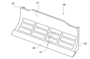
- FIG 20 is a schematic perspective view showing a blade 40 according to the third embodiment.
- the blade 40 is made of, for example, steel, and includes a blade body plate 41 that is curved so as to be convex toward the rear, a pair of side plates 42, 43 joined to both the left and right ends of the blade body plate 41, and a cutting edge 44 fixed to the lower end of the blade body plate 41.
- the rear surface of the blade body plate 41 is provided with brackets (not shown) to which the aforementioned support frames 331, 332 and lifting cylinder 332 (both shown in Figure 19) are connected.
- the adhesion suppression members 10 are installed on the front surface of the blade body plate 41 of the blade 40. Specifically, the adhesion suppression members 10 are installed so that their longitudinal direction is approximately parallel to the width direction of the blade body plate 41. Multiple adhesion suppression members 10 may be installed in a spread-out manner across the entire front surface of the blade body plate 41, but it is preferable to install them with a predetermined clearance between them above, below, left and right. The installation of the adhesion suppression members 10 is not particularly limited, but it is preferable to fix them by spot welding.
- [Fourth embodiment] 21 is a schematic side view showing a construction machine of a fourth embodiment.
- the construction machine of the fourth embodiment is an earth drill excavator 400 used in an earth drill method for cast-in-place pile construction.
- the earth drill excavator 400 is equipped with a drilling bucket 50 as a working tool.
- the drilling bucket 50 is rotated to excavate the ground while taking in the excavated soil into the drilling bucket 50, and the taken-in soil is repeatedly discharged to the ground, thereby excavating a borehole to a desired depth.
- the earth drill excavator 400 includes a lifting device 410 such as a crane, a rotary drive 430 attached to a front frame 420 of the lifting device 410, and a kelly bar 450 suspended by a wire 441 from a boom 440 of the lifting device 410.
- the drilling bucket 50 is attached to the tip of the kelly bar 450, and the rotational force of the rotary drive 430 is transmitted via the kelly bar 450.
- FIG. 22 is a schematic side view showing a drilling bucket 50 according to the fourth embodiment.
- FIG. 23 is a schematic vertical cross-sectional view showing a drilling bucket 50 according to the fourth embodiment.
- the drilling bucket 50 comprises a cylindrical bucket body 51 and a disk-shaped bottom cover 52 capable of closing the lower end opening of the bucket body 51.
- the bucket body 51 and the bottom cover 52 are formed of, for example, steel material.
- a socket 57 is provided at the upper end of the bucket body 51.
- the tip of the aforementioned kelly bar 450 (shown in FIG. 21) is connected to the socket 57 by a pin or the like.
- the bottom cover 52 is attached to the lower edge of the bucket body 51 via a hinge mechanism 55 so that it can be opened and closed freely. When excavating the ground, the bottom cover 52 closes the lower opening of the bucket body 51 ( Figure 22 shows the closed state).
- the underside of the bottom cover 52 is provided with a number of bits 53 for excavating the ground.
- the bottom cover 52 also has slits 54 for taking in the excavated soil into the bucket body 51. The excavated soil taken into the bucket body 51 is discharged to the ground by opening the bottom cover 52 ( Figure 23 shows the open state).
- the adhesion suppression members 10 are installed on the inner peripheral surface of the bucket body 51 and the inner surface of the bottom cover 52 (the surface facing the internal space of the bucket body 51 when the bottom cover 52 is closed). Specifically, the adhesion suppression members 10 of the bucket body 51 are installed so that their longitudinal direction is approximately parallel to the axial direction (vertically downward) of the bucket body 51.
- the number of adhesion suppression members 10 is not particularly limited, but it is preferable to install four or more members at equal intervals in the circumferential direction.
- the adhesion suppression members 10 may be installed in a spread manner on the inner peripheral surface of the bucket body 51, but it is preferable to install them with a predetermined clearance between them in the circumferential direction.
- the adhesion suppression members 10 of the bottom cover 52 are installed so that their longitudinal direction is approximately vertical when the bottom cover 52 is open.
- the method of fixing the adhesion suppression members 10 is not particularly limited, but it is preferable to fix them by spot welding.
- [Fifth embodiment] 24 is a schematic side view showing a construction machine of a fifth embodiment.
- the construction machine of the fifth embodiment is an all-casing excavator 500 used in the all-casing method for cast-in-place pile construction.
- the all-casing excavator 500 is equipped with a hammer grab 60 as a working tool.
- a casing tube 590 is rotated or swung while being pressed into the ground, and the soil in the casing tube 590 is discharged to the ground by the hammer grab 60. This operation is repeated while appropriately adding the casing tube 590, thereby excavating a borehole to a desired depth.
- the all-casing drilling machine 500 is equipped with a tubing device 510 and a lifting device 530 such as a crane.
- the tubing device 510 presses the casing tube 590 into the ground by rotating or swinging it.
- a cutter bit (not shown) is provided at the tip of the casing tube 590.
- the lifting device 530 is equipped with a jib 531.
- a crown 533 that detachably holds the hammer grab 60 is attached to the tip of a lifting wire 532 hanging down from the jib 531.
- the hammer grab 60 is suspended from the lifting device 530 so that it can be raised and lowered via a lifting operation wire 540 inserted through the center of the crown 533.
- FIG 25 is a schematic perspective view showing the hammer grab 60 according to the fifth embodiment in a closed state.
- Figure 26 is a schematic perspective view showing the hammer grab 60 according to the fifth embodiment in an open state.
- the hammer grab 60 comprises a hammer grab body 61, a slide block 62 provided on the upper part of the hammer grab body 61, and a pair of shells 63, 64 attached to the lower end of the hammer grab body 61 via a hinge mechanism 65 so as to be able to be opened and closed freely.
- Each shell 63, 64 is formed in an approximately semi-conical shape, and when in the closed state, they come into contact with each other to grasp the excavated soil.
- the lifting operation wire 540 (shown in FIG. 24) is reeled out and the slide block 62 is separated from the crown 533 (shown in FIG. 24).
- the slide block 62 is separated, the hammer grab 60 falls toward the ground and the shells 63, 64 dig into the ground with their shells 63, 64 open.
- the lifting operation wire 540 is then reeled in, the shells 63, 64 close and grab the excavated soil.
- the hammer grab 60 is pulled up and the slide block 62 is engaged with the crown 533.
- the lifting operation wire 540 is released and the shells 63, 64 open due to the biasing force of a spring (not shown).
- the adhesion suppression members 10 are installed on the inner circumferential surface of each shell 63, 64. Specifically, the adhesion suppression members 10 are installed so that their longitudinal direction faces approximately vertically when each shell 63, 64 is open. There is no particular limitation on the method for fixing the adhesion suppression members 10, but it is preferable to fix them by spot welding. There is also no particular limitation on the number of adhesion suppression members 10, but it is preferable to install at least two or more on each shell 63, 64.
- each shell 63, 64 by installing the adhesion suppression member 10 on the inner peripheral surface of each shell 63, 64, it is possible to effectively prevent the excavated soil grabbed by each shell 63, 64 from adhering to and accumulating on the inner peripheral surface of the shells 63, 64. In other words, it is possible to effectively prevent the excavated soil from remaining on the inner peripheral surface of the shells 63, 64 when the excavated soil is dumped onto the ground. This makes it possible to shorten the construction period of pile construction while reliably improving work efficiency.
- since the operation of applying impact to the hammer grab 60 to shake off the adhering residual soil from each shell 63, 64 is almost unnecessary or can be reduced to an extremely small number, it is possible to effectively prevent the generation of large noise and vibration. In addition, since there is less need for workers to approach the hammer grab 60 to clean it, it is also possible to improve safety.
- FIG. 27 is a schematic side view showing a construction machine of a sixth embodiment.
- the construction machine of the sixth embodiment is a horizontal multi-axis excavator 600 used in a diaphragm wall construction method.
- the horizontal multi-axis excavator 600 is equipped with an excavator 620 having a rotary cutter 70 as a working tool.
- the rotary cutter 70 is rotated while the excavator 620 is suspended in a trench filled with stabilizing liquid, thereby digging the ground vertically downward.
- the excavated soil is sucked up to the ground together with the stabilizing liquid, and after being subjected to processing such as soil separation, it is returned to the trench again for recycling.
- the horizontal multi-axis excavator 600 is equipped with a crawler-type lower running body 610, a platform 611 rotatably attached to the upper part of the lower running body 610, and a telescopic boom 612 that is mounted on the platform 611 so that it can be raised and lowered.
- the telescopic boom 612 is raised and lowered by a raising and lowering jack 613.
- An excavator 620 is suspended from the tip of the telescopic boom 612 via a wire 618 so that it can be raised and lowered.
- the platform 611 is also equipped with a mud lifting hose reel 615 that winds up a mud lifting hose 614, a winch 616 that raises and lowers the excavator 620 via the wire 618, a hydraulic hose reel 617 that winds up a hydraulic hose, a cable reel (not shown) that winds up a measurement cable, and the like.
- the excavator 620 is equipped with an excavator body 621.
- the excavator body 621 is provided with a plurality of attitude maintaining plates 622 that abut against the inner wall surface of the trench to maintain the attitude of the excavator body 621.
- a pair of hydraulically driven rotary cutters 70 are also arranged side by side at the lower end of the excavator body 621.
- a mud pump 623 is provided at approximately the center of the excavator body 621. The mud pump 623 sucks in the excavated soil and stabilizing liquid from a suction port 624 arranged between the rotary cutters 70, 70.
- the excavated soil and stabilizing liquid sucked from the suction port 624 are pumped to the mud lifting hose reel 615 via the mud lifting piping 625 and the mud lifting hose 614.
- the excavated soil and stabilizing liquid pumped to the mud lifting hose reel 615 are sent from the discharge port 619 to a mud water treatment plant (not shown) for treatment.
- FIG. 28 is a schematic diagram of the rotary cutter 70 according to the sixth embodiment, viewed from the direction of the rotation axis.
- FIG. 29 is a schematic diagram of the rotary cutter 70 according to the sixth embodiment, viewed from the radial direction.
- the rotary cutter 70 comprises a cylindrical rotating drum 71, a blade 72 having a substantially trapezoidal plate shape and provided so as to protrude radially from the outer circumferential surface of the rotating drum 71, and a cutter bit 74 fixed to the tip of the blade 72 via a holder 73.
- the multiple blades 72 are provided at a predetermined pitch in the circumferential direction on the outer circumferential surface of the rotating drum 71.
- the adhesion suppression member 10 is installed on the surface of the blade 72 of the rotary cutter 70. Specifically, the adhesion suppression member 10 is installed on the surface of the blade 72 facing the excavator body 621 (hereinafter, the inner surface) and on the surface of the blade 72 opposite the excavator body 621 (hereinafter, the outer surface). The adhesion suppression member 10 is installed so that its longitudinal direction is approximately parallel to the tangent direction of the rotating drum 71. There are no particular limitations on the method of fixing the adhesion suppression member 10, but it is preferable to fix it by spot welding.
- the adhesion prevention effect of soil and sand can be further improved by installing the adhesion prevention member 10 not only on the rotary cutter 70 but also on the surface of the excavator body 621.
- FIG. 30 is a schematic side view showing a construction machine of a seventh embodiment.
- the construction machine of the seventh embodiment is a ground improvement device 700 used in a power blender method for mid-layer mixing and processing works.
- the ground improvement device 700 is equipped with a trencher type agitator mixer 80 as a working tool.
- an improvement material such as a cement-based solidification material is sprayed from the trencher type agitator mixer 80 into the ground, and the trencher type agitator mixer 80 excavates the ground and agitates and mixes the improvement material with an agitator blade 88, thereby continuously creating a stable improved body.
- the ground improvement device 700 includes a backhoe 100 as a base machine.
- the backhoe 100 has the same structure as that shown in FIG. 1, so detailed description is omitted.
- the trencher type mixing machine 80 is attached to the tip of the arm 142 of the backhoe 100.
- the trencher type mixing machine 80 includes a substantially rectangular columnar frame 81, a driving sprocket 82 provided at the upper end of the frame 81, a driven sprocket 83 provided at the lower end of the frame 81, an endless drive chain 84 wound around each of the sprockets 82, 83, a plurality of chain tensioners 85 provided on the frame 81, and a joint 86 provided at the upper end of the frame 81.
- the joint 86 connects the frame 81 to the tip of the arm 142 so as to be rotatable around the longitudinal axis.
- the lower end side of the frame 81 is provided with an outlet 87 for spraying the improvement material.
- Multiple mixing blades 88 are arranged at a predetermined pitch around the outer periphery of the drive chain 84.
- the adhesion suppression member 10 is installed on the surface of the frame 81 of the trencher type agitator mixer 80. Specifically, the adhesion suppression member 10 is installed on the four sides of the frame 81, which is formed in a rectangular column shape, so that its longitudinal direction is approximately parallel to the longitudinal direction of the frame 81. There are no particular limitations on the method for fixing the adhesion suppression member 10, but it is preferable to fix it by spot welding.
- the location where the adhesion suppression member 10 is installed is not limited to the frame 81 of the trencher type agitation mixer 80, and it can also be installed on the agitation blade 88.
- FIG. 32 is a schematic plan view showing the agitation blade 88.
- FIG. 33 is a schematic side view showing the agitation blade 80.
- the agitation blade 88 is provided with a long plate-shaped base plate 88A fixed to the outer periphery of the drive chain 84, a plurality of excavation blades 88B fixed to the surface of the base plate 88A opposite to the drive chain 84 (hereinafter, the surface), and a long plate-shaped agitation blade 88C fixed to the surface of the base plate 88A opposite to the excavation blade 88B.
- the plurality of excavation blades 88B are arranged on the surface of the base plate 88A at a predetermined interval in the longitudinal direction of the base plate 88A.
- the agitation blade 88C is provided on the back surface of the base plate 88A at approximately right angles along the longitudinal direction of the base plate 88A.
- the adhesion suppression member 10 is installed on the surface of the base plate 88A (between the excavation blades 88B, 88B) and on the surface of the mixing blade 88C.
- the adhesion suppression member 10 can be widely applied to tools of construction machines other than the construction machine of the above embodiment. For example, if the adhesion suppression member 10 of the present disclosure is installed on the blade of a motor grader or the apron of a scraper, the adhesion suppression effect of excavated soil and the like can be obtained.
- the work object of the construction machine is described as soil, mud, snow, etc., but the same effect can be achieved with adhesive work objects such as bentonite, concrete, mortar, etc., regardless of the nature of the work object, whether liquid, semi-solid, or solid.
- the adhesion suppression member 10 has been described as having an upper layer of resin material 12 and a lower layer of metal material 11, but the lower layer can be formed of a base material other than metal as long as it is a material that can be bonded to the resin material 12.
- the adhesion suppression member 10 may be of a size that allows multiple sheets to be attached to the bottom plate portion 21 and side plate portions 22, 23 of the bucket 20.
- the shape of the adhesion suppression member 10 is not limited to a rectangular strip (rectangular plate), and may be a circle, an ellipse, a triangle, or a polygon with five or more sides.
- 10 adhesion suppression member, 11... metal material, 12... resin material, 20... bucket, 20'... skeleton bucket, 20A... bucket main body, 21... bottom plate, 21A... flat surface, 21B... curved surface, 22... left side plate, 23... right side plate, 24... edge plate, 25... bracket fixing plate, 27... mesh, 4A-4E... adapter, 5A-5E... claw, 6L, 6R... bracket, 30... bucket, 30A... bucket main body, 31... bottom plate, 31A... flat surface, 31B... curved surface, 32... left side plate, 33... right side plate, 40... blade, 41... blade main body, 50...
Landscapes
- Engineering & Computer Science (AREA)
- Mining & Mineral Resources (AREA)
- Mechanical Engineering (AREA)
- Civil Engineering (AREA)
- General Engineering & Computer Science (AREA)
- Structural Engineering (AREA)
- Geology (AREA)
- Life Sciences & Earth Sciences (AREA)
- Environmental & Geological Engineering (AREA)
- Fluid Mechanics (AREA)
- Physics & Mathematics (AREA)
- General Life Sciences & Earth Sciences (AREA)
- Geochemistry & Mineralogy (AREA)
- Soil Working Implements (AREA)
- Placing Or Removing Of Piles Or Sheet Piles, Or Accessories Thereof (AREA)
- Lining And Supports For Tunnels (AREA)
- Shovels (AREA)
Abstract
Priority Applications (2)
| Application Number | Priority Date | Filing Date | Title |
|---|---|---|---|
| US18/833,573 US20250137221A1 (en) | 2023-04-25 | 2024-03-22 | Adhesion suppressing member, work tool, claw member, and adhesion suppressing method |
| CA3242328A CA3242328A1 (en) | 2023-04-25 | 2024-03-22 | Adhesion suppressing member, work tool, claw member, and adhesion suppressing method |
Applications Claiming Priority (4)
| Application Number | Priority Date | Filing Date | Title |
|---|---|---|---|
| JP2023-071316 | 2023-04-25 | ||
| JP2023071316 | 2023-04-25 | ||
| JP2023199744A JP7763225B2 (ja) | 2023-04-25 | 2023-11-27 | 付着抑制部材及び、バケット |
| JP2023-199744 | 2023-11-27 |
Publications (1)
| Publication Number | Publication Date |
|---|---|
| WO2024224896A1 true WO2024224896A1 (fr) | 2024-10-31 |
Family
ID=93256182
Family Applications (1)
| Application Number | Title | Priority Date | Filing Date |
|---|---|---|---|
| PCT/JP2024/011299 Ceased WO2024224896A1 (fr) | 2023-04-25 | 2024-03-22 | Élément de limitation d'adhérence, outil de travail, élément de griffe et procédé de limitation d'adhérence |
Country Status (3)
| Country | Link |
|---|---|
| US (1) | US20250137221A1 (fr) |
| CA (1) | CA3242328A1 (fr) |
| WO (1) | WO2024224896A1 (fr) |
Families Citing this family (3)
| Publication number | Priority date | Publication date | Assignee | Title |
|---|---|---|---|---|
| USD1107077S1 (en) * | 2024-05-15 | 2025-12-23 | Caterpillar Inc. | Tip for a ground engaging machine implement |
| USD1104078S1 (en) * | 2024-05-15 | 2025-12-02 | Caterpillar Inc. | Tip for a ground engaging machine implement |
| USD1104079S1 (en) * | 2024-05-15 | 2025-12-02 | Caterpillar Inc. | Tip for a ground engaging machine implement |
Citations (18)
| Publication number | Priority date | Publication date | Assignee | Title |
|---|---|---|---|---|
| JPS5246004U (fr) * | 1975-09-29 | 1977-04-01 | ||
| JPS5588463U (fr) * | 1978-12-11 | 1980-06-18 | ||
| JPS5651859U (fr) * | 1979-09-28 | 1981-05-08 | ||
| JPS56159456U (fr) * | 1980-04-23 | 1981-11-27 | ||
| JPS5718048U (fr) * | 1980-06-30 | 1982-01-29 | ||
| JPS57114856U (fr) * | 1981-01-09 | 1982-07-16 | ||
| JPS57202454U (fr) * | 1981-06-17 | 1982-12-23 | ||
| JPS5850155U (ja) * | 1981-09-30 | 1983-04-05 | 株式会社竹中工務店 | 掘削機のバケツト |
| JPS5850153U (ja) * | 1981-09-30 | 1983-04-05 | 日立建機株式会社 | バケツト |
| JPS5872259U (ja) * | 1981-11-11 | 1983-05-16 | 新キャタピラ−三菱株式会社 | ブレ−ド乃至バケツト等の土工作業用ライニングアタツチメント |
| JPS645952U (fr) * | 1987-06-25 | 1989-01-13 | ||
| JPS6437560U (fr) * | 1987-08-31 | 1989-03-07 | ||
| JPH04117046U (ja) * | 1991-03-22 | 1992-10-20 | 博 小野寺 | シヨベル系掘削機のバケツト構造 |
| JP2000291047A (ja) * | 1999-04-12 | 2000-10-17 | Chiba Kogyo Kk | バケット |
| JP2001164595A (ja) * | 1999-12-06 | 2001-06-19 | Hitachi Constr Mach Co Ltd | 掘削バケット |
| JP2002201659A (ja) * | 2000-12-27 | 2002-07-19 | Marujun Heavy Industry Co Ltd | 土工機械のバケットアッタチメント |
| JP2009179958A (ja) * | 2008-01-29 | 2009-08-13 | Hitachi Constr Mach Co Ltd | 掘削バケット |
| US10066371B2 (en) * | 2014-09-05 | 2018-09-04 | Winter Equipment Company | Wear plates |
-
2024
- 2024-03-22 US US18/833,573 patent/US20250137221A1/en active Pending
- 2024-03-22 WO PCT/JP2024/011299 patent/WO2024224896A1/fr not_active Ceased
- 2024-03-22 CA CA3242328A patent/CA3242328A1/en active Pending
Patent Citations (18)
| Publication number | Priority date | Publication date | Assignee | Title |
|---|---|---|---|---|
| JPS5246004U (fr) * | 1975-09-29 | 1977-04-01 | ||
| JPS5588463U (fr) * | 1978-12-11 | 1980-06-18 | ||
| JPS5651859U (fr) * | 1979-09-28 | 1981-05-08 | ||
| JPS56159456U (fr) * | 1980-04-23 | 1981-11-27 | ||
| JPS5718048U (fr) * | 1980-06-30 | 1982-01-29 | ||
| JPS57114856U (fr) * | 1981-01-09 | 1982-07-16 | ||
| JPS57202454U (fr) * | 1981-06-17 | 1982-12-23 | ||
| JPS5850155U (ja) * | 1981-09-30 | 1983-04-05 | 株式会社竹中工務店 | 掘削機のバケツト |
| JPS5850153U (ja) * | 1981-09-30 | 1983-04-05 | 日立建機株式会社 | バケツト |
| JPS5872259U (ja) * | 1981-11-11 | 1983-05-16 | 新キャタピラ−三菱株式会社 | ブレ−ド乃至バケツト等の土工作業用ライニングアタツチメント |
| JPS645952U (fr) * | 1987-06-25 | 1989-01-13 | ||
| JPS6437560U (fr) * | 1987-08-31 | 1989-03-07 | ||
| JPH04117046U (ja) * | 1991-03-22 | 1992-10-20 | 博 小野寺 | シヨベル系掘削機のバケツト構造 |
| JP2000291047A (ja) * | 1999-04-12 | 2000-10-17 | Chiba Kogyo Kk | バケット |
| JP2001164595A (ja) * | 1999-12-06 | 2001-06-19 | Hitachi Constr Mach Co Ltd | 掘削バケット |
| JP2002201659A (ja) * | 2000-12-27 | 2002-07-19 | Marujun Heavy Industry Co Ltd | 土工機械のバケットアッタチメント |
| JP2009179958A (ja) * | 2008-01-29 | 2009-08-13 | Hitachi Constr Mach Co Ltd | 掘削バケット |
| US10066371B2 (en) * | 2014-09-05 | 2018-09-04 | Winter Equipment Company | Wear plates |
Also Published As
| Publication number | Publication date |
|---|---|
| CA3242328A1 (en) | 2025-06-17 |
| US20250137221A1 (en) | 2025-05-01 |
Similar Documents
| Publication | Publication Date | Title |
|---|---|---|
| US20250137221A1 (en) | Adhesion suppressing member, work tool, claw member, and adhesion suppressing method | |
| CN110678610A (zh) | 铲斗以及包括铲斗的岩土移动设备 | |
| US20110100882A1 (en) | Portable solids screening bucket | |
| CN105765131B (zh) | 用于铲斗的衬垫系统 | |
| US7832127B2 (en) | Apparatus for attaching a work tool to a loader | |
| JP2009179958A (ja) | 掘削バケット | |
| KR100729864B1 (ko) | 준설선 | |
| JP2011089326A (ja) | 管埋設用溝掘削機 | |
| JP7763225B2 (ja) | 付着抑制部材及び、バケット | |
| CN110171777B (zh) | 一种挖掘机改造的履带式吊车及用于该吊车的连接体 | |
| CN210288523U (zh) | 一种适合侧壁作业的挖掘机 | |
| JP2011026887A (ja) | 杭引抜き用作業機 | |
| Thombarer et al. | Shape optimization of an excavator bucket with the help of ANSYS software | |
| Frangakis | A review of lashing methods used in shaft sinking | |
| CN206015770U (zh) | 一种钩掘机 | |
| JP7252099B2 (ja) | 浚渫用アタッチメント及び浚渫システム | |
| JPH09316919A (ja) | 溝掘り装置および溝掘り方法 | |
| JP4031372B2 (ja) | 建設機械の排土装置 | |
| JP7603031B2 (ja) | 掘削機の使用方法 | |
| US883635A (en) | Bucket for dredgers. | |
| CN213233585U (zh) | 一种多功能挖掘机推土结构 | |
| CN86106946A (zh) | 改进的拉铲挖掘设备 | |
| US20250243647A1 (en) | Liner assembly for work implement | |
| CN215330151U (zh) | 一种建筑挖机用自清土装置 | |
| US12227918B2 (en) | Dipper lattice frame and wearable structural liner |
Legal Events
| Date | Code | Title | Description |
|---|---|---|---|
| WWE | Wipo information: entry into national phase |
Ref document number: 18833573 Country of ref document: US |
|
| WWE | Wipo information: entry into national phase |
Ref document number: 11202404407R Country of ref document: SG |
|
| 121 | Ep: the epo has been informed by wipo that ep was designated in this application |
Ref document number: 24796654 Country of ref document: EP Kind code of ref document: A1 |
|
| WWP | Wipo information: published in national office |
Ref document number: 18833573 Country of ref document: US |
|
| NENP | Non-entry into the national phase |
Ref country code: DE |
|
| 122 | Ep: pct application non-entry in european phase |
Ref document number: 24796654 Country of ref document: EP Kind code of ref document: A1 |